Tyco Safety Canada 005132XS433 Receiver User Manual Manual
Digital Security Controls Ltd. Receiver Manual
UserManual.wiki
>
Tyco Safety Canada
>
005132XS433 User Manual
Manual
Navigation menu
Upload a User Manual
Namespaces
Wiki Guide
HTML
PDF
Info
Views
User Manual
Discussion / Help
Navigation


![4This section describes how to enroll wireless devices (WLS904-433, WLS904P-433, WLS906-433, WLS907-433, WLS912L-433 and WLS925L-433), and wirelesskeys (WLS909-433/WLS919-433). For more information on these devices, read theinstruction sheet included with each device.3.1 A Note about Electronic Serial NumbersAn electronic serial number (ESN) is printed on the back of each wireless device.ESNs are used to enroll the wireless devices with the PC5132 receiver.In order to reduce the occurrence of wireless devices with the same serial number,6-digit serial numbers are now printed on the back of each wireless device. The 6-digit serial numbers include hexadecimal digits. For instructions on programminghexadecimal numbers, see your system Installation Manual, section 4: ‘How toProgram’.NOTE: 6-digit serial numbers are only supported on the following control panels:PC5020, PC501X, PC1565 and PC585 v2.0 and higher.The WLS904(P)-433, WLS906-433, WLS907-433, WLS912L-433, and WLS925L-433devices have both a 5-digit and a 6-digit serial number printed on them. Whenconnecting the PC5132 to a PC5010 v1.x panel, enter 5-digit serial numbers only. Whenconnecting the PC5132 to a PC5015 v2.x and higher, PC5020, PC5010, PC1565, orPC585 panel enter the 6-digit serial number.3.2 Enrolling Wireless Devices1. At a system keypad, enter [✱][8][Installer’s code] to go to the InstallerProgramming section.2. Enter programming section [804].3. Enter the 2-digit number corresponding to the zone the device is to occupy([01] to [32]).NOTE: Hardwired and wireless devices cannot be assigned to the same zone.PC5108 zone expander modules occupy zones in 2 groups of 4 (e.g. zones 9-12and zones 13-16). None of the zones assigned to a PC5108 module may be usedfor wireless devices. For more information on zone assignment, consult your sys-tem Installation Manual.4. Enter the device’s ESN. Follow the instructions in section 3.1 above.5. Record the serial number and the assigned zone number in theprogramming worksheets in the back of this manual.6. Continue with steps 3 - 5 until you have enrolled all wireless devices.7. To exit press [#]. The device is now enrolled on the system.NOTE: The devices will not work properly until you complete zone and partitionprogramming (see section 4).S E C T I O N 3Enrolling Wireless Devices](https://usermanual.wiki/Tyco-Safety-Canada/005132XS433/User-Guide-236508-Page-8.png)
![53.3 Enroll & Program Wireless KeysFor wireless keys to work on the system, you need to enroll them and then programthe function buttons. Wireless keys are not assigned to zones and require no zoneprogramming. You can enroll up to 16 wireless keys on the system.Enroll Wireless keys1. At a system keypad, enter [✱][8][Installer’s code] to go to the InstallerProgramming section.2. Enter programming section [804].3. Enter a 2-digit number [41]-[56] to assign the wireless key a slot. Thesenumbers correspond to wireless key numbers 01-16.4. Enter the key’s ESN. The entry must be six digits. If an older key with a 5-digit ESN is being enrolled, add the digit [0] to the beginning of the ESN.(E.g., if ESN=61234, enter 061234)5. The key is now enrolled on the system. Record the serial number and theassigned slot number in the programming worksheets in the back of thismanual.6. Repeat steps 3 - 5 until all wireless keys have been enrolled.7. (((((PC5020/PC5020/PC5020/PC5020/PC5020/PC501PC501PC501PC501PC501XXXXX only) only) only) only) only) By default, all wireless keys are assigned toPartition 1. To assign keys to Partition 2, enable the appropriate options inprogramming sections [91] and [92].NOTE: A wireless key can only be assigned to one partition.8. To exit press [#].Program the Wireless Key Function ButtonsWLS909-433/WLS919-433 wireless keys have four programmable function buttons.You must program a set of four functions for the buttons before any keys will work.After the functions are programmed, when you press and hold one of the four buttonsfor two seconds, the system will execute the programmed function.For systems not using partitions: program the function buttons in section [59].All wireless keys will have the same four functions.For systems using 2 partitions (PC5020/PC501X only): all wireless keys as-signed to Partition 1 will have the four functions programmed in section [59]. Allwireless keys assigned to Partition 2 will have the four functions programmed insection [60]. For example, if function button 1 in Section [59] is programmed forStay arming, then pressing the first button on wireless keys assigned to Partition 1will Stay arm Partition 1.NOTE: Wireless keys will not work when the partition they are assigned to is beingaccessed for zone bypassing or programming.1. At a system keypad, enter [✱][8][Installer’s code].2. Enter programming section [804].3. Enter programming section [59] for keys assigned to partition 1, or [60] forkeys assigned to partition 2.4. For each of the 4 function buttons, enter the 2-digit number of the functionyou want to select. See the programming worksheets in the back of thismanual for a list of function key options.W I R E L E S S D E V I C E S](https://usermanual.wiki/Tyco-Safety-Canada/005132XS433/User-Guide-236508-Page-9.png)
![65. Record your programming choices in the worksheets in the back of themanual.6. To exit press [#].3.4 Identified Wireless KeysReporting by the system of openings/closings by individual wireless keys andcommand output [✱][7] activation by wireless key buttons may be supported oncertain control panels. To do this, the system will reserve access codes 17 – 32 forwireless keys 01-16 respectively. You must program one access code for eachwireless key (using [✱][5] access code programming) for this feature to workcorrectly.NOTE: Program these access codes on the system after you have connected thePC5132 to the Keybus (see section 2.4).Refer to your system Installation Manual for information on access code programming.Opening/Closing By Wireless Key ReportingNOTE: The Identified Wireless Key Closing option is only available with the PC5020,PC501X, PC1565, PC585 v2.0 and higher by turning section [015] option 4 off.To enable the reporting of openings and closings by identified wireless keys:• Make sure the control panel is v2.0 or higher• Program a valid access code for each key• Program a closing and opening reporting code for each key’s access code• Turn off the Quick Arm option in section [015] option [4] of the controlpanel programmingTo ensure that an unidentified wireless key cannot disarm the system, turn offsection [017], option [1] (in the control panel programming). This option is availablein control panels with software version 2.1 or higher.Command Output ActivationNOTE: The Identified Wireless Key Command Output Activation feature is only avail-able with the PC5020, PC501X, PC1565 and PC585 v2.0 and higher.To enable command output activation by wireless keys, ensure that:• The control panel is v2.0 or higher• Program a valid access code for each key• Enable the PGM output attribute Requires Access Code for each PGMoutput programmed as [✱][7][1-4] in sections [141] to [154].Now that you have enrolled all the wireless devices, you will need to program thesystem to work properly with the devices. See section 4 for more information.W I R E L E S S D E V I C E S](https://usermanual.wiki/Tyco-Safety-Canada/005132XS433/User-Guide-236508-Page-10.png)
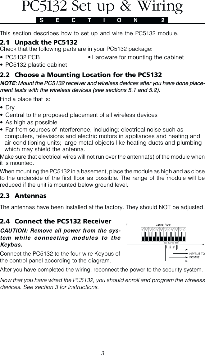
![74.1 Program Zones and PartitionsNow that you have enrolled the wireless devices, you should complete all zoneprogramming on the system. Although the exact programming required variesdepending on which control panel the PC5132 is connected to, you should checkthat the following programming areas are completed correctly for each wirelesszone:• Enable zones and/or assign zones to one or more partitions (programmingsections [201]-[209]).• Program the definition for each zone (programming sections [001]-[004]).• Enable the wireless zone attribute for each wireless zone (PC585, PC1565,PC5020, PC501X v2.0 and up only) (sections [101]-[132]).See your system Installation Manual, for more information on each of the aboveprogramming sections.4.2 Enable PC5132 SupervisionThe control panel will supervise the PC5132 receiver via the Keybus after at leastone device has been enrolled on the module (see section 3.2 “Enrolling WirelessDevices”).To activate module supervision, after you enroll the first device(s):1. Exit and then re-enter Installer Programming2. Enter programming section [902]. Wait approximately 1 minute.3. To exit press [#].The system will generate a General System Supervisory trouble if the module isremoved from the Keybus. If you need to remove the PC5132 module from anexisting system, you will have to disable supervision of the PC5132.NOTE: Deleting all devices from the PC5132 or defaulting the PC5132 will causea PC5132 supervisory faultTo disable PC5132 supervision:1. Disconnect the PC5132 from the Keybus2. Enter [✱][8][Installer’s Code]3. Enter [902]. The control panel will clear all supervision and re-scan the system forconnected modules. The scan will take approximately one minute.4. To exit press [#].To review which modules the control panel is currently supervising:1. Enter [✱][8][Installer’s Code]2. Enter [903] to display all modules. On LED keypads, light [17] will indicatethat the PC5132 is present on the system. On LCD keypads, scroll until themodule name appears on the display.3. To exit press [#].S E C T I O N 4Other Programming](https://usermanual.wiki/Tyco-Safety-Canada/005132XS433/User-Guide-236508-Page-11.png)
![8If the PC5132 module does not show on the keypad, one of the followingconditions may be present:• the module is not connected properly to the Keybus• there is a problem with the Keybus wiring run• the module does not have enough power• no devices have been enrolled on the PC51324.3 Enable Supervision of Wireless ZonesNOTE: (for PC5010 v1.x control panels only) In order for wireless zones to besupervised, you must enable Double End of Line (DEOL) supervision in the PC5010control panel. For more information, refer to your Installation Manual.NOTE: (PC5020, PC501X, PC1565, PC585 v2.0 and higher only) For wirelesssupervision to work, you must enable the wireless zone attribute on all wirelesszones (sections [101] to [132], option [8] ON).Wireless Supervisory WindowEach wireless zone (WLS906-433,WLS904-433, WLS904P-433, WLS907-433,WLS912L-433, or WLS925L-433) will send a supervisory signal every 12 minutes. Ifthe receiver does not receive a signal within the time programmed for the WirelessSupervisory Window, it will generate a supervisory fault.To program the wireless supervisory window:1. Enter [✱][8][Installer’s Code] to enter Installer Programming.2. Enter [804] to enter the PC5132 Module Programming.3. Enter section [81].4. Enter the time period for the supervisory window. The window isprogrammed in 15 minute increments. The default programming is 10(x15minutes), which is equal to 2.5 hours. Valid entries are (08) - (96), equalto 2 - 24 hours.5. To exit press [#].Disable/Enable Zone SupervisionAll wireless zones have supervision enabled by default. To disable supervision forany zone, enter the following at any system keypad:1. Enter [✱][8][Installer’s Code] to enter Installer Programming.2. Enter [804] to enter the PC5132 Module Programming.3. Enter sections [82], [83], [84] and [85]. Enable or disable supervision foreach wireless zone by turning each relevant option on or off.4. To exit press [#].4.4 Jamming Signal DetectionThe PC5132 receiver detects jamming signals that can prevent the receiver fromproperly receiving transmissions from enrolled devices. When jamming signals aredetected, the control panel will generate a General System Tamper trouble, whichwill be reported immediately. Jamming signal detection is turned ON by default.To turn OFF jamming signal detection:O T H E R P R O G R A M M I N G](https://usermanual.wiki/Tyco-Safety-Canada/005132XS433/User-Guide-236508-Page-12.png)
![9O T H E R P R O G R A M M I N G1. Enter [✱][8][Installer’s Code] to enter Installer Programming.2. Enter [804] to enter the PC5132 Module Programming.3.Turn ON section [90], option [7].4. To exit press [#].4.5 PC5132 Software DefaultReturning the PC5132 programming to factory default settings is a quick way toremove all the enrolled devices from the system and reset all the programming insection [804].NOTE: Performing this procedure will not change any programming sections ex-cept [804]. Resetting the control panel to factory default settings will not return thePC5132 module to factory default settings.To restore the PC5132 programming to the factory default settings:1. Enter [✱][8] [Installer’s Code].2. Enter programming section [996].3. Enter the Installer’s Code, followed by [996] again. The software for thePC5132 will be restored to its factory default settings.4. To continue programming the unit, exit Installer Programming by pressing[#] and then re-enter Installer Programming by entering [✱][8] [Installer’sCode].For instructions on restoring the default programming of the control panel or anyother connected module, see your system Installation Manual.4.6 Deleting Wireless DevicesTo remove a wireless device from the system, follow the guideline for enrolling awireless device (see section 3.2). Program the ESN as [000000]. The wirelessdevice for the zone will be removed.NOTE: You may need to remove power from the panel in order to clear troublescaused by deleted zones.Now that you have completed all PC5132 related programming, you can test andmount the receiver and devices. See section 5 for more information.](https://usermanual.wiki/Tyco-Safety-Canada/005132XS433/User-Guide-236508-Page-13.png)
![105.1 Test the Reception of Wireless DevicesIt is very important to test the proposed placement of each wireless device beforeit is mounted. Following these steps will test the signal strength between the PC5132-433 and the wireless devices.You can test all of the devices together (global placement testing) or test each deviceindividually. To test all the devices together, see Testing All Wireless DevicesTogether. To test wireless devices individually, see Testing Individual Devices.NOTE: After you have enrolled the wireless devices, you must exit and then re-enter installer’s mode at least once before you can perform a placement test.Testing All Wireless Devices Together:1. Temporarily put the wireless devices in the places you want to mount them.2. At a system keypad, enter [✱][8][Installer’s Code].3. Enable the Global Module Placement test by entering section [804].Then enter sub-section [90] and turn on option [8].4. Press [#] twice.5. Enter programming section [904], then enter [01].6. Activate one of the devices being tested until a result is displayed on thekeypad or sounded by the keypad or bell:WLS904-433/WLS904P: To perform a Placement Test on the WLS904-433,remove the detector from the back plate and then replace it. Once the detectoris replaced on the backplate the LED on the detector will flash rapidly 5 times toindicate that it has sent a transmission. The panel will show and/or sound theresult of the placement test on the keypad. To perform a 2nd and 3rd test, repeatthis procedure. Carefully replace the backplate onto the detector, ensuringCarefully replace the backplate onto the detector, ensuringCarefully replace the backplate onto the detector, ensuringCarefully replace the backplate onto the detector, ensuringCarefully replace the backplate onto the detector, ensuringthat “TOP”that “TOP”that “TOP”that “TOP”that “TOP” is facing upward, or you may damage the tamper switch. is facing upward, or you may damage the tamper switch. is facing upward, or you may damage the tamper switch. is facing upward, or you may damage the tamper switch. is facing upward, or you may damage the tamper switch.NOTE: When you remove the detector from the backplate (tamper the unit), thedetector will also be put into “Detector Walk Test” mode. While in Walk Test Modethe detector will activate the LED when motion is detected. The detector will alsosend a signal to the receiver 5 seconds after motion is detected, indicated by 5rapid flashes by the LED. The LED will only work in this fashion for 10 motiondetections after a tamper/restore. Note, that the panel will ignore these transmis-sion signals with respect to a placement test. The only way in which the panel willacknowledge a placement test, is if the backplate has, each time, been removedand restored.WLS906-433: Remove the detector from its backplate, wait 5 seconds andreattach it, or hold a magnet near the raised line on the outer rim, then remove it.WLS907-433/WLS925L-433: Open the contact by moving the magnet awayfrom the unit. The keypad will show/sound the test result. After the first testresult has been generated (about 10 seconds) close the contact togenerate another test result. If the unit is attached to a door or a window,open and close the door or window to activate the device.WLS909-433/WLS919-433: Press any function key at several different locations.WLS912L-433: Press and hold the test mode tab for 5 seconds. Releasethe test mode tab.S E C T I O N 5Testing & Mounting](https://usermanual.wiki/Tyco-Safety-Canada/005132XS433/User-Guide-236508-Page-14.png)
![11T E S T I N G & M O U N T I N GRead the test results at the keypad:Result LED Keypad LCD Keypad Buzzer/BellGood Light 1 On Steady “Good” 1 Beep/SquawkBad Light 3 On Steady “Bad” 3 Beeps/SquawksActivate the device until you get 3 good results in a row.You may mount the WLS devices where results were good.Devices indicating a bad result must be moved to another location. You mayonly have to move the device a few inches to correct a bad result.NOTE: Do not mount any device where a “bad” test result was indicated.7. Go to the next device to be tested and activate it until the test result isdisplayed/sounded.NOTE: Wait until the placement test of one device is shown/sounded before begin-ning to test the next device.Continue to test the devices until both the PC5132 and the devices are in goodlocations. If several wireless devices produce BAD test results, you may need tomove the PC5132 to a better location. (See section 2.2 for tips on finding alocation for the PC5132.)8. To exit the placement test and return to installer programming, press [#] twice.Testing Individual Wireless Devices:1. Temporarily place the wireless device in the place you want to mount it.2. At a system keypad, enter [✱][8][Installer’s Code].3. Enter programming section [904].4 Enter the 2-digit zone number for the device to be tested.5. Activate the device being tested until a result is displayed on the keypad orsounded by the keypad or bell. (Same as step 5 in the Global PlacementTest section, previous page.)6. To test another device, press [#] once, then repeat steps 4 - 5. Continue to testthe devices until both the PC5132 and the devices are in good locations.If several wireless devices produce BAD test results, you may need to movethe PC5132 to a better location. (See section 2.2 for tips on finding alocation for the PC5132.)7. To exit the placement test and installer programming, press [#] twice.Testing Individual Wireless Keys:You cannot use the individual device test described above to test WLS909-433/WLS919-433 wireless keys. To ensure that the PC5132 receiver is receivingtransmissions from the devices, use the function keys on the Wireless Keys atseveral different points in the installation.](https://usermanual.wiki/Tyco-Safety-Canada/005132XS433/User-Guide-236508-Page-15.png)
![13S E C T I O N 6Additional Notes6.1 Trouble ConditionsThe control panel always watches for possible trouble conditions. If a troublecondition occurs, the keypad “Trouble” light will turn on and the keypad will beep.Press [✱][2] to display the trouble conditions.The following trouble conditions apply to the PC5132 and/or any enrolled devices.General System Tamper - This trouble is generated when the PC5132 plasticcover is removed and/or if there is a jamming condition present.General System Supervisory - This trouble will be indicated if the panel losescommunication with any module connected to the Keybus. The event buffer willlog a detailed description of the event.Device Low Battery - This trouble is generated when a wireless device exhibits alow battery condition. Press [7] one, two, or three times to view which devicesare experiencing battery failure. An LED keypad will indicate battery failureusing zone lights 1 to 8.Zone Tamper - This trouble is generated when an enrolled wireless device isremoved from its mounting location.Zone Fault - Each wireless zone will send a supervisory signal every 64minutes. If the receiver does not receive a signal within the timeprogrammed for the Wireless Supervisory Window, it will generate a zonefault.Tamper SwitchesThere are two tamper switches on the PC5132 board. Removing both the plasticcover and/or the PC5132 from its mounting location will cause a general systemtamper.6.2 Jamming Signal DetectionThe PC5132 receiver detects jamming signals that can prevent the receiver fromproperly receiving transmissions from enrolled devices. See section 4.4 “JammingSignal Detection” for information on jamming signal detection programming.6.3 Wireless Zone Low Battery TransmissionWithin any transmission, the device will indicate the status of the battery. If a batteryis low, the system will indicate a Device Low Battery trouble.The system will delay reporting the event to the central station for the number ofdays programmed for Zone Low Battery Transmission Delay in section [370].This will prevent unnecessary reporting of the event if the user has been instructedon how to replace batteries.](https://usermanual.wiki/Tyco-Safety-Canada/005132XS433/User-Guide-236508-Page-17.png)
![16[804] 5132--433 Wireless Expansion Programming• 6-digit entry is required. See Section 3.1 “A note on Electronic SerialNumbers” for details on programming 6-digit serial numbers.Zone Serial NumbersDefault = 000000[01] Zone 1 l_____l_____l_____l_____l_____l_____l[02] Zone 2 l_____l_____l_____l_____l_____l_____l[03] Zone 3 l_____l_____l_____l_____l_____l_____l[04] Zone 4 l_____l_____l_____l_____l_____l_____l[05] Zone 5 l_____l_____l_____l_____l_____l_____l[06] Zone 6 l_____l_____l_____l_____l_____l_____l[07] Zone 7 l_____l_____l_____l_____l_____l_____l[08] Zone 8 l_____l_____l_____l_____l_____l_____l[09] Zone 9 l_____l_____l_____l_____l_____l_____l[10] Zone 10 l_____l_____l_____l_____l_____l_____l[11] Zone 11 l_____l_____l_____l_____l_____l_____l[12] Zone 12 l_____l_____l_____l_____l_____l_____l[13] Zone 13 l_____l_____l_____l_____l_____l_____l[14] Zone 14 l_____l_____l_____l_____l_____l_____l[15] Zone 15 l_____l_____l_____l_____l_____l_____l[16] Zone 16 l_____l_____l_____l_____l_____l_____l[17] Zone 17 l_____l_____l_____l_____l_____l_____l[18] Zone 18 l_____l_____l_____l_____l_____l_____l[19] Zone 19 l_____l_____l_____l_____l_____l_____l[20] Zone 20 l_____l_____l_____l_____l_____l_____l[21] Zone 21 l_____l_____l_____l_____l_____l_____l[22] Zone 22 l_____l_____l_____l_____l_____l_____l[23] Zone 23 l_____l_____l_____l_____l_____l_____l[24] Zone 24 l_____l_____l_____l_____l_____l_____l[25] Zone 25 l_____l_____l_____l_____l_____l_____l[26] Zone 26 l_____l_____l_____l_____l_____l_____l[27] Zone 27 l_____l_____l_____l_____l_____l_____l[28] Zone 28 l_____l_____l_____l_____l_____l_____l[29] Zone 29 l_____l_____l_____l_____l_____l_____l[30] Zone 30 l_____l_____l_____l_____l_____l_____l[31] Zone 31 l_____l_____l_____l_____l_____l_____l[32] Zone 32 l_____l_____l_____l_____l_____l_____lProgramming WorksheetsS E C T I O N 8](https://usermanual.wiki/Tyco-Safety-Canada/005132XS433/User-Guide-236508-Page-20.png)
![17Wireless Key Serial NumbersDefault = 000000[41] Key 01 l_____l_____l_____l_____l_____l_____l[42] Key 02 l_____l_____l_____l_____l_____l_____l[43] Key 03 l_____l_____l_____l_____l_____l_____l[44] Key 04 l_____l_____l_____l_____l_____l_____l[45] Key 05 l_____l_____l_____l_____l_____l_____l[46] Key 05 l_____l_____l_____l_____l_____l_____l[47] Key 07 l_____l_____l_____l_____l_____l_____l[48] Key 08 l_____l_____l_____l_____l_____l_____lP R O G R A M M I N G W O R K S H E E T S[49] Key 09 l_____l_____l_____l_____l_____l_____l[50] Key 10 l_____l_____l_____l_____l_____l_____l[51] Key 11 l_____l_____l_____l_____l_____l_____l[52] Key 12 l_____l_____l_____l_____l_____l_____l[53] Key 13 l_____l_____l_____l_____l_____l_____l[54] Key 14 l_____l_____l_____l_____l_____l_____l[55] Key 15 l_____l_____l_____l_____l_____l_____l[56] Key 16 l_____l_____l_____l_____l_____l_____lWireless Key Function Key OptionsEntry Key Description Entry Key Description00 Null Key 16 [✱][0] Quick Exit01-02 For Future Use 17 [✱][1] Reactivate Stay/Aways03 Stay Arm 18 For Future Use04 Away Arm 19 [✱][7][3] Command Output #305 [✱][9] No-Entry Arm 20 For Future Use06 [✱][4] Chime ON/OFF 21 [✱][7][4] Command Output #407 [✱][6][——][4] System Test 22-26 For Future Use08-12 For Future Use 2727 Disarm (OFF)13 [✱][7][1] Command Output #1 2828 Fire Alarm14 [✱][7][2] Command Output #2 /Sensor Reset2929 Auxiliary Alarm15 For Future Use 30 Panic Alarm](https://usermanual.wiki/Tyco-Safety-Canada/005132XS433/User-Guide-236508-Page-21.png)
![18P R O G R A M M I N G W O R K S H E E T SPartition 1 Wireless Key OptionsDefault = 00[59] Function Key 1 l____l____lFunction Key 3 l____l____lFunction Key 2 l____l____lFunction Key 4 l____l____lPartition 2 Wireless Key Options[60] Function Key 1 l____l____lFunction Key 3 l____l____lFunction Key 2 l____l____lFunction Key 4 l____l____lSupervision[81] Wireless Supervisory Window Default = 10l____l____lThe window is programmed in 15 minute increments. Thedefault programming is 96 (x 15minutes), which is equal to 24hours. Valid entries are (08) - (96), equal to 2 - 24 hours.[82] Zone Device Supervision Options (1-8)Default = ON Option ON Option OFFl________lOption 1 Zone 01 Supervision enabled Disabledl________lOption 2 Zone 02 Supervision enabled Disabledl________lOption 3 Zone 03 Supervision enabled Disabledl________lOption 4 Zone 04 Supervision enabled Disabledl________lOption 5 Zone 05 Supervision enabled Disabledl________lOption 6 Zone 06 Supervision enabled Disabledl________lOption 7 Zone 07 Supervision enabled Disabledl________lOption 8 Zone 08 Supervision enabled Disabled[83] Zone Device Supervision Options (9-16)Default = ON Option ON Option OFFl________lOption 1 Zone 09 Supervision enabled Disabledl________lOption 2 Zone 10 Supervision enabled Disabledl________lOption 3 Zone 11 Supervision enabled Disabledl________lOption 4 Zone 12 Supervision enabled Disabledl________lOption 5 Zone 13 Supervision enabled Disabledl________lOption 6 Zone 14 Supervision enabled Disabledl________lOption 7 Zone 15 Supervision enabled Disabledl________lOption 8 Zone 16 Supervision enabled Disabled](https://usermanual.wiki/Tyco-Safety-Canada/005132XS433/User-Guide-236508-Page-22.png)
![19P R O G R A M M I N G W O R K S H E E T S[84] Zone Device Supervision Options (17-24)Default = ON Option ON Option OFFl________lOption 1 Zone 17 Supervision enabled Disabledl________lOption 2 Zone 18 Supervision enabled Disabledl________lOption 3 Zone 19 Supervision enabled Disabledl________lOption 4 Zone 20 Supervision enabled Disabledl________lOption 5 Zone 21 Supervision enabled Disabledl________lOption 6 Zone 22 Supervision enabled Disabledl________lOption 7 Zone 23 Supervision enabled Disabledl________lOption 8 Zone 24 Supervision enabled Disabled[85] Zone Device Supervision Options (25-32)Default = ON Option ON Option OFFl________lOption 1 Zone 25 Supervision enabled Disabledl________lOption 2 Zone 26 Supervision enabled Disabledl________lOption 3 Zone 27 Supervision enabled Disabledl________lOption 4 Zone 28 Supervision enabled Disabledl________lOption 5 Zone 29 Supervision enabled Disabledl________lOption 6 Zone 30 Supervision enabled Disabledl________lOption 7 Zone 31 Supervision enabled Disabledl________lOption 8 Zone 32 Supervision enabled Disabled[90] Other OptionsDefault = OFF Option ON Option OFFl________lOptions 1-6 For future usel________lOption 7 RF Jam Detect Disabled RF Jam Detect Enabledl________lOption 8 Global Placement Test Individual Placement Test[91] Wireless Keys (1-8) Partition AssignmentsDefault = OFF Option ON Option OFFl________lOption 1 Wireless Key 01 on partition 2 On partition 1l________lOption 2 Wireless Key 02 on partition 2 On partition 1l________lOption 3 Wireless Key 03 on partition 2 On partition 1l________lOption 4 Wireless Key 04 on partition 2 On partition 1](https://usermanual.wiki/Tyco-Safety-Canada/005132XS433/User-Guide-236508-Page-23.png)
![20P R O G R A M M I N G W O R K S H E E T Sl________lOption 5 Wireless Key 05 on partition 2 On partition 1l________lOption 6 Wireless Key 06 on partition 2 On partition 1l________lOption 7 Wireless Key 07 on partition 2 On partition 1l________lOption 8 Wireless Key 08 on partition 2 On partition 1[92] Wireless Keys (9-16) Partition AssignmentsDefault = OFF Option ON Option OFFl________lOption 1 Wireless Key 09 on partition 2 On partition 1l________lOption 2 Wireless Key 10 on partition 2 On partition 1l________lOption 3 Wireless Key 11 on partition 2 On partition 1l________lOption 4 Wireless Key 12 on partition 2 On partition 1l________lOption 5 Wireless Key 13 on partition 2 On partition 1l________lOption 6 Wireless Key 14 on partition 2 On partition 1l________lOption 7 Wireless Key 15 on partition 2 On partition 1l________lOption 8 Wireless Key 16 on partition 2 On partition 1P R O G R A M M I N G W O R K S H E E](https://usermanual.wiki/Tyco-Safety-Canada/005132XS433/User-Guide-236508-Page-24.png)