Tyco Safety Canada 005501Z32433 LCD5501Z32-433 & PICON-433 keypads User Manual LCD5501Z32 433 v1 0 imum en na 29005206 r001 p65
Digital Security Controls Ltd. LCD5501Z32-433 & PICON-433 keypads LCD5501Z32 433 v1 0 imum en na 29005206 r001 p65
Installation manual
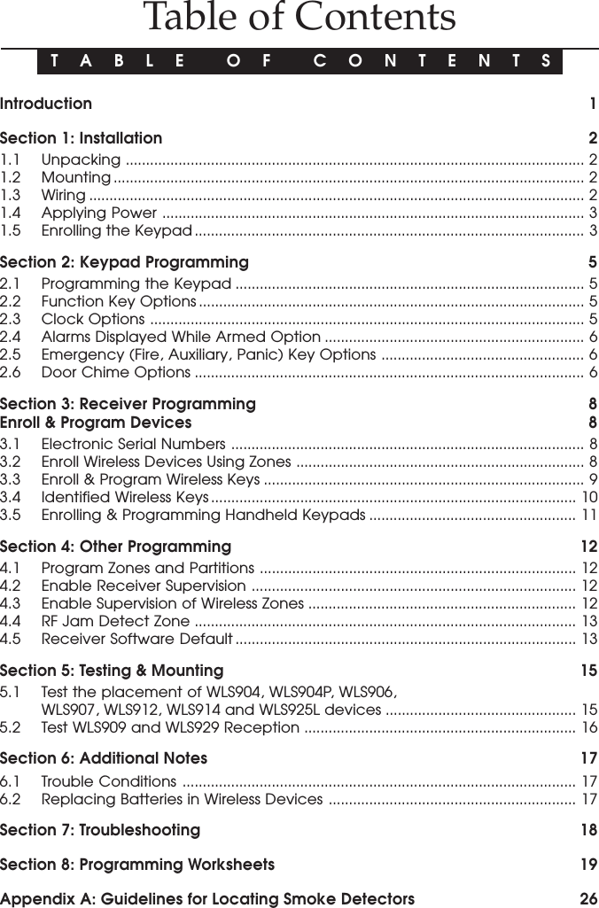
![3I N S T A L L A T I O N1.4 Applying PowerOnce all wiring is complete, apply power to the control panel:1. Connect the battery leads to the battery.2. Connect the AC transformer.For more information on control panel power specifications, see the controlpanel Installation Manual.NOTE: Do not connect the power until all wiring is complete.1.5 Enrolling the KeypadOnce all wiring is complete, you will need to enter a 2-digit number that tells thesystem the partition and slot assignment of the keypad.If your system has partitions, you will also need to assign the keypad to apartition (1st digit).The slot assignment (2nd digit) tells the panel which keypad slots are occupied.The panel can then generate a fault when a keypad supervisory signal is notpresent. There are eight available slots for keypads. LCD5501Z32-433 keypadsare always assigned to slot 1 by default. You will need to assign each keypad toits own slot (1 to 8).NOTE: The LCD5501Z32-433 enrolls as two modules: 1 = keypad section of the LCD5501Z32-43317 = receiver section of the LCD5501Z32-433Enter the following at each keypad installed on the system:1. Enter Installer Programming by pressing [*][8][Installer’s Code]2. Press [000] for Keypad Programming3. Press [0] for Partition and Slot Assignment4. Enter a two digit number to specify the partition and slot assignment.NOTE: If your system does not have partitions, enter [1] for the first digit.1st digit Enter 0 for Global KeypadEnter 1 for Partition 1 KeypadEnter 2 for Partition 2 Keypad2nd digit Enter 1 to 8 for Slot Assignment5. Press the [#] key twice to exit programming.6. After assigning all keypads, perform a supervisory reset by entering[*][8][Installer’s Code][902]. The panel will now supervise all assigned keypadsand enrolled modules on the system.To review which modules the control panel is currently supervising:1. Enter [✱][8][Installer’s Code]2. Enter [903] to display all modules. On the LCD5501Z32-433 keypad, 11111 and 1111177777 willscroll on the keypad to indicate that the LCD5501Z32-433 is present on the system.11111 designates the keypad section, and 1717171717 is used to show the receiver sectionis also supervised. If using an LCD5501Z keypad, scroll until the module nameappears on the display.3. To exit press [#].](https://usermanual.wiki/Tyco-Safety-Canada/005501Z32433/User-Guide-114512-Page-6.png)
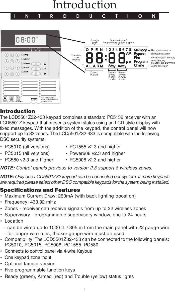
![52.1 Programming the KeypadThere are several programming options available for the LCD5501Z32-433keypad. These are described below. Record all your programming choices inthe programming worksheets included in this manual.Programming the LCD5501Z32-433 is similar to programming the rest of thesystem. When you are in the LCD5501Z32-433 programming sections, the keypadwill display which options are turned on along the top of the display. To turn anoption on or off, press the number corresponding to the option on the number pad.The numbers of the options that are currently turned ON will be displayed.For example, if options 1 and 2 are on, the display will look like this:For information on programming the rest of your security system, please refer toyour system’s Installation Manual.2.2 Function Key OptionsThe function keys are programmed in sections [1] to [5]. By default, the 5 functionkeys on the keypad are programmed as Stay Arm (03), Away Arm (04), Chime(06), Sensor Reset (14) and Quick Exit (16). You can change the function of eachkey on every keypad. Please see your system’s Installation Manual for instruc-tions on programming the keys, and a complete list of all the function key optionsavailable for your system.2.3 Clock OptionsThe LCD5501Z32-433 will display the current time after 30 seconds of no keypresses. To set the correct time and date for the system, please refer to yoursystem’s Instruction Manual. You can change how the keypad displays the timewith the following options. To change the clock options:1. Enter [*][8][Installer’s code]2. Enter [000] to go to keypad programming3. Enter section [6] to go to clock options.4. To turn any of the options on or off, press [1], [2], or [3]:NOTE: If the Time does not display on keypad option is selected, make sure thatthe Keypad displays time when zones are open option is also selected.[1] ON = Time displays on keypadOFF = Time does not display on keypad[2] ON = Clock display is in AM/PM format(e.g. 08:00 AM)OFF = Clock display is in 24-hour format (e.g. 20:00)Keypad ProgrammingS E C T I O N 2](https://usermanual.wiki/Tyco-Safety-Canada/005501Z32433/User-Guide-114512-Page-8.png)
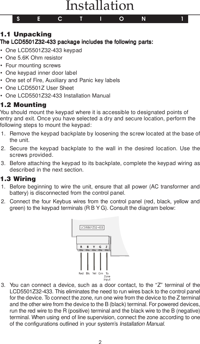
![6[3] ON = Keypad does not display time when zones are openOFF = Keypad displays time when zones are open5. When you are finished programming the clock options, press [#] to exit.2.4 Alarms Displayed While Armed OptionYou can disable the display of alarms on the keypad when the system is armed.The display of alarms is enabled by default. To disable the display of alarmswhen the system is armed, turn off section [6], option [5]:1. Enter [*][8][Installer’s code]2. Enter [000] to go to keypad programming3. To turn the display of alarms on or off, enter section [6].4. Turn option [5] on or off:[5] ON = Alarms not displayed while system is armedOFF = Alarms are always displayed while system is armed5. When you are finished, press [#] to exit.2.5 Emergency (Fire, Auxiliary, Panic) Key OptionsYou can enable or disable the Fire, Auxiliary and Panic keys at each keypad.These keys are enabled by default. Please see your system’s InstallationManual for more information on these keys and their options. To turn any of theemergency keys on or off on the keypad:1. Enter [*][8][Installer’s code]2. Enter [000] to go to keypad programming3. Enter section [7].4. To turn the emergency key options on or off, press [1], [2], or [3]:[1] ON = Fire key enabledOFF = Fire key disabled[2] ON = Auxiliary key enabledOFF = Auxiliary key disabled[3] ON = Panic key enabledOFF = Panic key disabled5. When you are finished, press [#] to exit.2.6 Door Chime OptionsYou can program the LCD5501Z32-433 keypad to sound a tone when anyzone is opened or closed. There are two parts to the LCD5501Z32-433 doorchime programming:• Program if the LCD5501Z32-433 will chime when zones are opened and/or closed.• Program the type of sound the LCD5501Z32-433 will make when an individualzone is opened or closed.For the door chime feature to work, you will also need to turn on the Door Chimeattribute for each zone that will trigger the chime. This programming is done inthe control panel software. Refer to your control panel’s Installation Manual formore information.K E Y P A D P R O G R A M M I N G](https://usermanual.wiki/Tyco-Safety-Canada/005501Z32433/User-Guide-114512-Page-9.png)
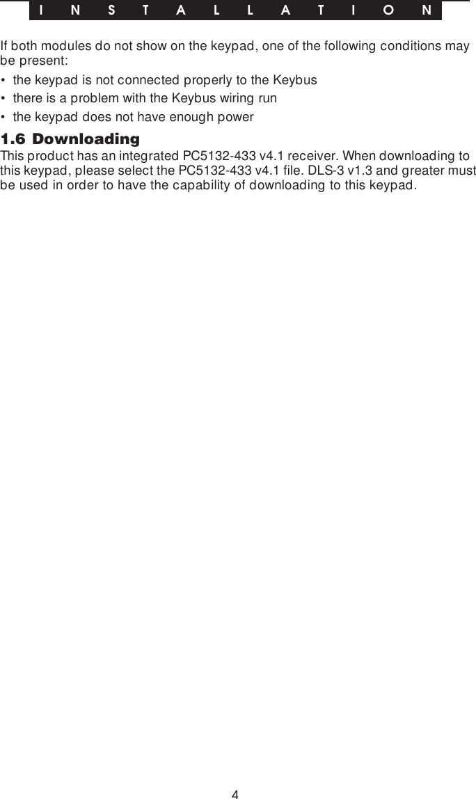
![7Door Chime on Zone Openings/ClosingsYou can program each LCD5501Z32-433 keypad to sound a door chime when zonesare opened and/or when they are closed. By default, LCD5501Z32-433 keypads areprogrammed to sound door chimes on both zone openings and closings.To change the door chime opening/closing settings, at each LCD5501Z32-433keypad:1. Enter [*][8][Installer’s code]2. Enter [000] to go to keypad programming3. Enter section [6].4. To turn the options on or off, press [6] or [7]:[6] ON = Door Chime Enabled for Zone OpeningsOFF = Door Chime Disabled for Zone Openings[7] ON = Door Chime Enabled for Zone ClosingsOFF = Door Chime Disabled for Zone Closings5. When you are finished, press [#] to exit.Door Chime SoundsYou can program the LCD5501Z32-433 keypad to make different door chimesounds for individual zones, or groups of zones. Each LCD5501Z32-433keypad can make any of four door chime sounds for each zone that triggers thedoor chime:· 4 quick beeps (default sound)· ‘Bing – Bing’ tone· ‘Ding – Dong’ tone· ‘Alarm’ toneNOTE: For a zone to be able to trigger the door chime sound, the Door Chime zoneattribute must also be enabled in the control panel programming. Please see yourcontrol panel Installation Manual.To change the door chime sounds:1. Enter [*][8][Installer’s code].2. Enter [*] to go to door chime sound programming.3. Enter a 2-digit number for the zone you want to program [01] - [32].4. Turn one of the following options on by pressing [1], [2], [3], or [4]:[1] 4 quick beeps (default sound)[2] ‘Bing – Bing’ tone[3] ‘Ding – Dong’ tone[4] ‘Alarm’ toneNOTE: Make sure that only one of the above options is turned on. If more than one ison, the keypad will sound the first option that is enabled. If none of the options areselected, the keypad will not make any sound when the zone is opened or closed.5. To program the door chime sound for another zone, repeat steps 3 and 4.6. When you are finished programming the door chime sounds, press [#] to exit.K E Y P A D P R O G R A M M I N G](https://usermanual.wiki/Tyco-Safety-Canada/005501Z32433/User-Guide-114512-Page-10.png)
![8 Receiver ProgrammingS E C T I O N 3Enroll & Program DevicesThis section describes how to enroll and program:• wireless devices using zones (WLS904, WLS904P, WLS906, WLS907, WLS912,WLS914 and WLS925L)• wireless keys (WLS909, WLS929)For more information on these devices, read the instruction sheet included witheach device.3.1 A Note about Electronic Serial NumbersAn electronic serial number (ESN) is printed on the back of each wireless device.ESNs are used to enroll the wireless devices with the LCD5501Z32-433 keypad.In order to reduce the occurrence of wireless devices with the same serial number,6-digit serial numbers are now printed on the back of each wireless device.NOTE: 6-digit serial numbers are only supported on the following control panels:PC5010 v2.x and higher, PC5015 v2.2, PC5008, PC1555 and PC580.The 6-digit serial numbers include hexadecimal digits. For instructions on programming,hexadecimal numbers, see your system Installation Manual, section 4: How to Program.When connecting the LCD5501Z32-433 to a PC5010 or PC5015 v1.x panel, enter 5-digit serial numbers only.When connecting the LCD5501Z32-433 to a PC5010 v2.x, PC5015 v2.x, PC5008,PC1555 or PC580 panel follow the instructions below.Old Wireless Device ESNsYou can use older devices on all versions of the LCD5501Z32-433 keypad, eventhough they only have a 5-digit ESN. When using older wireless devices:Enter [0] + 5-digit ESN3.2 Enroll Wireless Devices Using Zones (WLS904, WLS904P,WLS906, WLS907, WLS912, WLS914, WLS925L)Enroll wireless devices which use zones (universal transmitters, motion detec-tors, smoke detectors, and panic pendants):1. At a system keypad, enter [✱][8][Installer’s code] to go the installer’sprogramming section.2. Enter programming section [804].3. Enter the 2-digit number corresponding to the zone the device is to occupy([01] to [32]).NOTE: Hardwired and wireless devices cannot be assigned to the same zone.PC5108 zone expander modules occupy zones in 2 groups of 4 (e.g. zones 9-12and zones 13-16). None of the zones assigned to a PC5108 module may be usedfor wireless devices. For more information on zone assignment, consult your systemInstallation Manual.4. Enter the device’s ESN. The entry must be six digits. If an older device with a](https://usermanual.wiki/Tyco-Safety-Canada/005501Z32433/User-Guide-114512-Page-11.png)
![95-digit ESN is being enrolled, add the digit [0] to the beginning of the ESN.(E.g., ESN=21234, enter 021234)5. The device is now enrolled on the system. Record the serial number and theassigned zone number in the programming worksheets in the back of thismanual.6. Continue with steps 3 - 5 until you have enrolled all wireless devices.7. To exit press [#].NOTE: The devices will not work properly until you complete zone and partitionprogramming (see section 4).3.3 Enroll & Program Wireless Keys (WLS909/WLS929)For wireless keys to work on the system, you need to enroll them and then programthe function buttons. Wireless keys are not assigned to zones and require no zoneprogramming. You can enroll up to 16 wireless keys on the system.Enroll Wireless keys1. At a system keypad, enter [✱][8][Installer’s code] to go to the Installer’sProgramming section.2. Enter programming section [804].3. Enter a 2-digit number [41]-[56] to assign the wireless key a slot. These numberscorrespond to wireless key numbers 01-16.4. Enter the key’s ESN. The entry must be six digits. If an older key with a 5-digitESN is being enrolled, add the digit [0] to the beginning of the ESN. (E.g.ESN=61234, enter 061234)5. The key is now enrolled on the system. Record the serial number and theassigned slot number in the programming worksheets in the back of thismanual.6. Repeat steps 3 - 5 until all wireless keys have been enrolled.7. (PC5010 and PC5015 only)(PC5010 and PC5015 only)(PC5010 and PC5015 only)(PC5010 and PC5015 only)(PC5010 and PC5015 only) By default, all wireless keys are assigned toPartition 1. To assign keys to Partition 2, enable the appropriate options inprogramming sections [91] and [92].NOTE: A wireless key can only be assigned to one partition.8. To exit press [#].Program the WLS909/WLS929 Function ButtonsWLS909 wireless keys have four programmable function buttons. You mustprogram a set of four functions for the buttons before any keys will work. After thefunctions are programmed, when you press and hold one of the four buttons fortwo seconds, the system will execute the programmed function.For systems not using partitions: program the function buttons in section [59].All wireless keys will have the same four functions.For systems using 2 partitions (PC5010 and PC5015 only): all wireless keysassigned to Partition 1 will have the four functions programmed in section [59]. Allwireless keys assigned to Partition 2 will have the four functions programmed insection [60]. For example, if function button 1 in Section [59] is programmed forE N R O L L & P R O G R A M D E V I C E S](https://usermanual.wiki/Tyco-Safety-Canada/005501Z32433/User-Guide-114512-Page-12.png)
![10Stay arming, then pressing the first button on wireless keys assigned to Partition1 will Stay arm Partition 1.NOTE: Wireless keys will not work when the partition they are assigned to isbeing accessed for zone bypassing or programming.1. At a system keypad, enter [✱][8][Installer’s code].2. Enter programming section [804].3. Enter programming section [59] for keys assigned to partition 1, or [60] for keysassigned to partition 2.4. For each of the 4 function buttons, enter the 2-digit number of the function youwant to select. See the programming worksheets for a list of function keyoptions.5. Record your programming choices in the worksheets in the back of the manual.6. To exit press [#].3.4 Identified Wireless KeysReporting by the system of openings/closings by individual wireless keys andcommand output [✱][7] activation by wireless key buttons may be supported oncertain control panels. To do this, the system will reserve access codes 17 – 32for wireless keys 01-16 respectively. You must program one access code foreach wireless key (using [✱][5] access code programming) for this feature towork correctly.Refer to your system Installation Manual for information on access codeprogramming.Opening/Closing By Wireless Key ReportingNOTES: The Identified Wireless Key Closing option is only available with thePC5010 v2.0, PC5008 v2.0 and higher by turning section [015] option 4 off.The Identified Wireless Key Opening option is only available with the PC1555 v2.1,PC580 v2.1, PC5008 v2.1 and higher, PC5015 v2.2 and higher by turning section[017] option 1 off.To enable the reporting of closings by identified wireless keys:• Make sure the control panel is v2.0 or higher• Program a valid access code for each key• Program a closing reporting code for each key’s access code• Disable the Quick Arm option in section [015] option [4]To enable the reporting of openings by identified wireless keys:• Make sure the control panel is v2.1 or higher• Program a valid access code for each key• Program an opening reporting code for each key’s access code• Enable the WLS Key Uses Access Codes by turning section [017] option [1] off.E N R O L L & P R O G R A M D E V I C E S](https://usermanual.wiki/Tyco-Safety-Canada/005501Z32433/User-Guide-114512-Page-13.png)
![11E N R O L L & P R O G R A M D E V I C E SCommand Output ActivationNOTE: The Identified Wireless Key Command Output Activation feature is onlyavailable with the PC5010, PC5015, PC5008, PC1555 and PC580 v2.0 and higher.To enable command output activation by wireless keys, do the following:• Make sure the control panel is v2.0 or higher• Program a valid access code for each key• Enable the PGM output attribute Requires Access Code for each PGM outputprogrammed as [✱][7][1-4] in sections [141] to [154].3.5 Deleting Wireless DevicesTo remove a wireless device from the system, follow the guideline for adding awireless device. Program the ESN as [000000]. The wireless device for the zonewill be removed.NOTE: You may need to remove power from the panel in order to clear troublescaused by deleted zones.Now that you have enrolled all the wireless devices, you will need to program thesystem to work properly with the devices. See section 4 for more information.](https://usermanual.wiki/Tyco-Safety-Canada/005501Z32433/User-Guide-114512-Page-14.png)
![124.1 Program Zones and PartitionsNow that you have enrolled the wireless devices, you should complete all zoneprogramming on the system. Although the exact programming required variesdepending on which control panel the LCD5501Z32-433 is connected to, youshould check that the following programming areas are completed correctly foreach wireless zone:• Enable zones and/or assign zones to one or more partitions (programmingsections [201]-[209]).• Program the definition for each zone (programming sections [001]-[004]).NOTE: WLS906 wireless smoke detectors must be assigned to zones defined asDelay 24-hr fire (wireless) [87] or Standard 24-hr fire (wireless) [88] for propersupervision.• Enable the wireless zone attribute for each wireless zone (PC580, PC1555,PC5008, PC5010 v2.0 and up, PC5015 v2.2 and up only) (programming sections[101]-[132]).See your system Installation Manual, for more information on each of the aboveprogramming sections.4.2 Enable Receiver SupervisionThe control panel will automatically supervise the receiver via the Keybus one-minute after at least one device has been enrolled on the module. The system willgenerate a General System Supervisory trouble if the module is removed from theKeybus. If you need to remove the LCD5501Z32-433 from an existing system, youwill have to disable supervision of the PC5132.4.3 Enable Supervision of Wireless ZonesNOTE (for PC5010 v1.x control panels only): For UL Listed installation, DoubleEOL resistors must be enabled in the PC5010 for the wireless zones to be super-vised. If normally Closed or Single EOL resistors are selected the PC5010 will notbe able to supervise the wireless devices. If a wireless device stops sending asupervisory signal (the unit stops functioning) the panel will not indicate a super-visory trouble condition unless Double EOL resistors are used. In addition, allhardwire zones must be wired for Double EOL resistors. For more information,refer to your PC5010 v1.x Installation Manual.NOTE (PC5010 v2.0 and higher, PC5015 v2.2 and higher, PC5008, PC1555, PC580only): For wireless supervision to work, you must enable the wireless zone attributeon all wireless zones (sections [101] to [132], option [8] ON).NOTE: The RF Jam Detect zone must have the supervision option disabled.Wireless Supervisory WindowEach wireless zone (WLS904, WLS904P, WLS906, WLS907, WLS912, WLS914,WLS925L) will send a supervisory signal every 64 minutes. If the receiver does notreceive a signal within the time programmed for the Wireless Supervisory Window,it will generate a supervisory fault.S E C T I O N 4Other Programming](https://usermanual.wiki/Tyco-Safety-Canada/005501Z32433/User-Guide-114512-Page-15.png)
![13To program the wireless supervisory window:1. Enter [✱][8][Installer Code] to enter Installer Programming.2. Enter [804] to enter into Receiver Programming.3. Enter sections [81].4. Enter the time period for the supervisory window (valid entries are 01-24 hours).5. To exit press [#].Disable/Enable Zone SupervisionAll wireless zones have supervision enabled by default. To disable supervision forany zone, enter the following at any system keypad:1. Enter [✱][8][Installer Code] to enter Installer Programming.2. Enter [804] to enter the PC5132 Module Programming.3. Enter sections [82], [83], [84] and [85]. Disable or enable supervision for eachwireless zone by turning each relevant option on or off.4. To exit press [#].4.4 RF Jam Detect ZoneFor RF jamming detection to work, you must select an unused zone to be used asthe RF Jam Detect zone. When the receiver detects an attempt to jam the RFsignal, the RF Jam Detect zone will be violated and the system will generate atamper signal. When the jamming signal is gone, the RF Jam Detect zone closesand the system sends a tamper restore signal.To enable RF jamming detection:1. Enter [✱][8] [Installer’s Code].2. Enter programming section [804].3. Select an unused zone to be the RF Jam Detect zone. Enter the 2-digit number([01] to [32]) of the RF Jam Detect zone on the keypad, then program theserial number as [200000].3. Enter section [93]. Enter the 2-digit number of the RF Jam Detect zone ([01] to[32]) in the programming section.4. Disable supervision for the RF Jam detect zone by turning the relevant optionoff in section [82], [83], [84] or [85]. (See section 4.3 for more information.)5. RF jamming detection is now enabled. To exit Installer programming, press [#].4.5 Receiver Software DefaultReturning the receiver programming to factory default settings is a quick way toremove all the enrolled devices from the system and reset all the programming insection [804].NOTE: Performing this procedure will not change any programming sections except[804]. Resetting the control panel to factory default settings will not return thePC5132 to factory default settings.O T H E R P R O G R A M M I N G](https://usermanual.wiki/Tyco-Safety-Canada/005501Z32433/User-Guide-114512-Page-16.png)
![14O T H E R P R O G R A M M I N GTo restore the PC5132 programming to the factory default settings, perform thefollowing:1. Enter [✱][8] [Installer’s Code].2. Enter programming section [996].3. Enter the Installer’s Code, followed by [996] again. Press [#]. The software forthe receiver section will be restored to its factory default settings.4. Press [#] to exit Installer Programming. After a software default, you must exitand then re-enter Installer Programming before attempting to program thereceiver section.For instructions on restoring the default programming of the control panel or anyother connected module, see your system Installation Manual.O T H E R P R O G R A M M I N G](https://usermanual.wiki/Tyco-Safety-Canada/005501Z32433/User-Guide-114512-Page-17.png)
![15S E C T I O N 5Testing & Mounting5.1 Test the placement of the WLS904, WLS904P,WLS906, WLS907, WLS912, WLS914 and WLS925LIt is very important to test the proposed placement of each wireless device before it ismounted. Following these steps will test the placement of the wireless motion detectors(WLS904(P)/WLS914), wireless smoke detectors (WLS906), wireless glassbreakdetectors (WLS912) and wireless door/window contacts (WLS907/WLS925L), basedon the signal strength between the LCD5501Z32-433 and the device.NOTE: You cannot test the Wireless Keys (WLS909/WLS929) in this mode. Seesection 5.2 for instructions on testing these devices. You cannot run a placementtest on the RF Jam Detect zone.1. Temporarily place the device you want to test in the place you want to mount it.2. At a system keypad, enter [✱][8][Installer Code].3. Enter programming section [904].4 Enter the 2-digit zone number for the device to be tested.5. Activate the device being tested until a result is displayed on the keypad orsounded by the keypad or bell.WLS904, WLS904P & WLS914: Remove the detector from its backplate, waitfor 1-2 seconds, then reattach the detector to its backplate.WLS906: Remove the detector from its backplate, wait for 5 seconds, thenreattach the detector to its backplate. Or hold a magnet near the raised line onthe outer rim. Then remove the magnet.WLS907 & WLS925L: Open and close the contact by moving the magnetaway from the unit. If the unit is attached to a door or a window, open andclose the door or window to activate the device.WLS912: Press and hold the test mode tab for 5 seconds. Release the testmode tab. The keypad will display the test result.6. Read the test results at the keypad:Result LED Keypad LCD Keypad Buzzer/BellGood Light 1 On Steady “Good” 1 Beep/SquawkFair Light 2 On Steady “Fair” 2 Beeps/SquawksBad Light 3 On Steady “Bad” 3 Beeps/SquawksActivate the device until you get 3 good or fair results in a row. Wait 10 secondsbetween each test on the same device.You may mount wireless devices where results were good or fair.Devices indicating a bad result must be moved to another location. You may onlyhave to move the device a few inches to correct a bad result.NOTE: Do not mount any device where a “bad” test result was indicated.If several wireless devices produce BAD test results, you may need to movethe LCD5501Z32-433 to a better location.7. To test another device, press [#] once, then repeat steps 4 - 6. Continue to testthe devices until both the LCD5501Z32-433 and the devices are in good locations.8. To exit installer programming, press [#] twice.](https://usermanual.wiki/Tyco-Safety-Canada/005501Z32433/User-Guide-114512-Page-18.png)
![17S E C T I O N 6Additional Notes6.1 Trouble ConditionsThe control panel always watches for possible trouble conditions. If a troublecondition occurs, the keypad “Trouble” light will turn on and the keypad will beep.Press [✱][2] to display the trouble conditions.The following trouble conditions apply to the receiver portion (identified as thePC5132 by the panel) and/or any enrolled devices. For a description of alltroubles, please see your system Installation Manual.• General System Tamper• General System Supervisory• Zone Fault• Device Low Battery• Zone TamperWireless Zone Low Battery TransmissionWithin the supervisory transmission, the device will indicate the status of thebattery. If a battery is low, the system will indicate a Device Low Battery trouble.The system will delay reporting the event to the central station for the number ofdays programmed for Zone Low Battery Transmission Delay in section [370].This will prevent unnecessary reporting of the event if the user has been instructedon how to replace batteries.6.2 Replacing Batteries in Wireless Devices1 Remove the cover of the device from its backplate. This creates a tampercondition on the zone.2 Refer to the battery installation instructions on the Installation Sheet of eachcomponent. Be sure to note the proper orientation of the batteries as youinstall them.3 When the fresh batteries are in place, re-attach the cover to the backplate. Thetamper is restored and the zone sends a battery trouble restoral signal to thereceiver. The battery trouble is now clear and the device should function normally.NOTE: When batteries in one device need to be replaced, the batteries in alldevices should be replaced at the same time.](https://usermanual.wiki/Tyco-Safety-Canada/005501Z32433/User-Guide-114512-Page-20.png)
![18S E C T I O N 7Troubleshooting1. When I enter the 2-digit zone number when adding a wireless device,the keypad gives me a long beep.You cannot enter ESNs unless the LCD5501Z32-433 is properly connected to theKeybus. See sections 1 & 3 for instructions on setting up and wiring the PC5132 module.2. I have entered the ESN for the device but when I violate the device, thezone does not show open on the keypad.Check the following:• Ensure the ESN has been entered correctly• Ensure that the zone is enabled for the partition (if partition programming isused).• Ensure that the wireless zone is not assigned to a zone used by PC5108 modules.• Ensure that the zone is programmed for something other than “Null Operation.”Wireless smoke detectors must be assigned to zones defined as type [87] or [88].3. When I try a module placement test I get no result or “Bad” results.Check the following (see sections 5.1 and 5.2 for more information on testingdevices):• Verify that you are testing the correct zone• Verify that the correct ESN was entered when the device was enrolled• Verify that the device is in range of the LCD5501Z32-433. Try testing the devicein the same room as the receiver.• Confirm that the LCD5501Z32-433 is properly connected to the Keybus.• Check that you are testing the zone correctly.• Check that the batteries are working and installed correctly.• Look for large metal objects that may be preventing the signal from reachingthe LCD5501Z32-433.The device must be located where consistent “Good” results are obtained. Ifseveral devices show “Bad” results, or if panic pendants and wireless keysoperate inconsistently, move the receiver.4. The LED on the motion detector does not turn on when I walk in front ofthe unit.The LED is for walk test purposes only. See your WLS904 Instruction Sheet forwalk test instructions.](https://usermanual.wiki/Tyco-Safety-Canada/005501Z32433/User-Guide-114512-Page-21.png)
![19S E C T I O N 8Programming Worksheets[000] Keypad Programming1. Enter [*][8][Installer’s code]2. Enter [000] to go to keypad programming[0] Keypad EnrollmentValid entries are 01-18; e.g. enter [11] for partition 1, slot 1. Default = 111st digit Enter 0 for Global KeypadEnter 1 for Partition 1 KeypadEnter 2 for Partition 2 Keypad2nd digit Enter 1 to 8 for Slot AssignmentSlotSlotSlotSlotSlot: I________I________I[1]-[5] Function Key Assignments[1] Key 1 [2] Key 2 [3] Key 3 [4] Key 4 [5] Key 5Defaults: 03 04 06 14 16Stay Away Chime Reset ExitI________I________I I________I________I I________I________I I________I________I I________I________I[6] LCD5501Z32-433 Keypad OptionsDefault Option On OffON I________I 1 Local Clock Display Enabled Display DisabledON I________I 2 Local Clock Displays AM/PM Displays 24-hour TimeOFF I________I 3 Open Zones Override Clock Display Do Not Override ClockOFF I________I 4 For Future UseOFF I________I 5 Alarms Not Displayed While Armed Always Displayed While ArmedOFF I________I 6 Door Chime Enabled for Zone Openings Door Chime DisabledOFF I________I 7 Door Chime Enabled for Zone Closings Door Chime DisabledOFF I________I 8 For Future Use[7] Emergency Key OptionsDefault Option On OffON I________I 1 [F] Key Enabled [F] Key DisabledON I________I 2 [A] Key Enabled [A] Key DisabledON I________I 3 [P] Key Enabled [P] Key DisabledOFF I________I 4-8 For Future Use](https://usermanual.wiki/Tyco-Safety-Canada/005501Z32433/User-Guide-114512-Page-22.png)
![20[*] Door Chime Sound Programming1. Enter [*][8][Installer’s code][*]2. Enter 2-digit zone number [01] - [32], then select door chime sound option [1] - [4].Repeat for each zone that is to sound a chime.Zone Location [1] [2] [3] [4]4 Beeps “Bing-bing”“Ding-dong”Alarm tone(default)[01] I__________________________________________________________________I I________I I________I I________I I________I[02] II__________________________________________________________________I I________I I________I I________I I________I[03] I__________________________________________________________________I I________I I________I I________I I________I[04] I__________________________________________________________________I I________I I________I I________I I________I[05] I__________________________________________________________________I I________I I________I I________I I________I[06] I__________________________________________________________________I I________I I________I I________I I________I[07] I__________________________________________________________________I I________I I________I I________I I________I[08] I__________________________________________________________________I I________I I________I I________I I________I[09] I__________________________________________________________________I I________I I________I I________I I________I[10] I__________________________________________________________________I I________I I________I I________I I________I[11] I__________________________________________________________________I I________I I________I I________I I________I[12] I__________________________________________________________________I I________I I________I I________I I________I[13] I__________________________________________________________________I I________I I________I I________I I________I[14] I__________________________________________________________________I I________I I________I I________I I________I[15] I__________________________________________________________________I I________I I________I I________I I________I[16] I__________________________________________________________________I I________I I________I I________I I________I[17] I__________________________________________________________________I I________I I________I I________I I________I[18] I__________________________________________________________________I I________I I________I I________I I________I[19] I__________________________________________________________________I I________I I________I I________I I________I[20] I__________________________________________________________________I I________I I________I I________I I________I[21] I__________________________________________________________________I I________I I________I I________I I________I[22] I__________________________________________________________________I I________I I________I I________I I________I[23] I__________________________________________________________________I I________I I________I I________I I________I[24] I__________________________________________________________________I I________I I________I I________I I________I[25] I__________________________________________________________________I I________I I________I I________I I________I[26] I__________________________________________________________________I I________I I________I I________I I________I[27] I__________________________________________________________________I I________I I________I I________I I________I[28] I__________________________________________________________________I I________I I________I I________I I________I[29] I__________________________________________________________________I I________I I________I I________I I________I[30] I__________________________________________________________________I I________I I________I I________I I________I[31] I__________________________________________________________________I I________I I________I I________I I________I[32] I__________________________________________________________________I I________I I________I I________I I________IP R O G R A M M I N G W O R K S H E E T S](https://usermanual.wiki/Tyco-Safety-Canada/005501Z32433/User-Guide-114512-Page-23.png)
![21[804] Wireless Expansion Programming• 6-digit entry is required. See Section 3.1 “A note on Electronic Serial Numbers”for details on programming 6-digit serial numbers.• When enrolling devices with 5-digit serial numbers on the LCD5501Z32-433,the first digit must be zero (0), followed by the 5-digit serial number (6-digitstotal). For example, to enter the serial number 42345 on a LCD5501Z32-433,enter “042345.”Zone Serial NumbersDefault = 000000[01] Zone 1 l_____l_____l_____l_____l_____l_____l[02] Zone 2 l_____l_____l_____l_____l_____l_____l[03] Zone 3 l_____l_____l_____l_____l_____l_____l[04] Zone 4 l_____l_____l_____l_____l_____l_____l[05] Zone 5 l_____l_____l_____l_____l_____l_____l[06] Zone 6 l_____l_____l_____l_____l_____l_____l[07] Zone 7 l_____l_____l_____l_____l_____l_____l[08] Zone 8 l_____l_____l_____l_____l_____l_____l[09] Zone 9 l_____l_____l_____l_____l_____l_____l[10] Zone 10 l_____l_____l_____l_____l_____l_____l[11] Zone 11 l_____l_____l_____l_____l_____l_____l[12] Zone 12 l_____l_____l_____l_____l_____l_____l[13] Zone 13 l_____l_____l_____l_____l_____l_____l[14] Zone 14 l_____l_____l_____l_____l_____l_____l[15] Zone 15 l_____l_____l_____l_____l_____l_____l[16] Zone 16 l_____l_____l_____l_____l_____l_____l[17] Zone 17 l_____l_____l_____l_____l_____l_____l[18] Zone 18 l_____l_____l_____l_____l_____l_____l[19] Zone 19 l_____l_____l_____l_____l_____l_____l[20] Zone 20 l_____l_____l_____l_____l_____l_____l[21] Zone 21 l_____l_____l_____l_____l_____l_____l[22] Zone 22 l_____l_____l_____l_____l_____l_____l[23] Zone 23 l_____l_____l_____l_____l_____l_____l[24] Zone 24 l_____l_____l_____l_____l_____l_____l[25] Zone 25 l_____l_____l_____l_____l_____l_____l[26] Zone 26 l_____l_____l_____l_____l_____l_____l[27] Zone 27 l_____l_____l_____l_____l_____l_____l[28] Zone 28 l_____l_____l_____l_____l_____l_____l[29] Zone 29 l_____l_____l_____l_____l_____l_____l[30] Zone 30 l_____l_____l_____l_____l_____l_____l[31] Zone 31 l_____l_____l_____l_____l_____l_____l[32] Zone 32 l_____l_____l_____l_____l_____l_____lP R O G R A M M I N G W O R K S H E E T S](https://usermanual.wiki/Tyco-Safety-Canada/005501Z32433/User-Guide-114512-Page-24.png)
![22P R O G R A M M I N G W O R K S H E E T SWireless Key Serial NumbersDefault = 000000[41] Key 01 l_____l_____l_____l_____l_____l_____l[42] Key 02 l_____l_____l_____l_____l_____l_____l[43] Key 03 l_____l_____l_____l_____l_____l_____l[44] Key 04 l_____l_____l_____l_____l_____l_____l[45] Key 05 l_____l_____l_____l_____l_____l_____l[46] Key 05 l_____l_____l_____l_____l_____l_____l[47] Key 07 l_____l_____l_____l_____l_____l_____l[48] Key 08 l_____l_____l_____l_____l_____l_____l[49] Key 09 l_____l_____l_____l_____l_____l_____l[50] Key 10 l_____l_____l_____l_____l_____l_____l[51] Key 11 l_____l_____l_____l_____l_____l_____l[52] Key 12 l_____l_____l_____l_____l_____l_____l[53] Key 13 l_____l_____l_____l_____l_____l_____l[54] Key 14 l_____l_____l_____l_____l_____l_____l[55] Key 15 l_____l_____l_____l_____l_____l_____l[56] Key 16 l_____l_____l_____l_____l_____l_____l Wireless Key Function Key OptionsEntry Key Description Entry Key Description00 Null Key 16 [✱][0] Quick Exit01-02For Future Use17 [✱][1] Reactivate Stay/Aways03 Stay Arm 18For Future Use04 Away Arm *19 [✱][7][3] Command Output #305 [✱][9] No-Entry Arm 20 For Future Use06 [✱][4] Chime ON/OFF *21 [✱][7][4] Command Output #407 [✱][6][——][4] System Test 22-26For Future Use08-12For Future Use27 Disarm (OFF)*13 [✱][7][1] Command Output #1 28 Fire Alarm*14 [✱][7][2] Command Output #2 /Sensor Reset 29 Auxiliary Alarm15For Future Use30 Panic Alarm*Sensor Reset can be used when the LCD5501Z32-433 is connected to the PC5010.Command outputs are not available for PC5010 software v1.x.](https://usermanual.wiki/Tyco-Safety-Canada/005501Z32433/User-Guide-114512-Page-25.png)
![23P R O G R A M M I N G W O R K S H E E T SDefault = 00Partition 1 Wireless Key Options[59] Function Key 1 l____l____lFunction Key 3 l____l____lFunction Key 2 l____l____lFunction Key 4 l____l____lPartition 2 Wireless Key Options[60] Function Key 1 l____l____lFunction Key 3 l____l____lFunction Key 2 l____l____lFunction Key 4 l____l____lSupervision[81] Wireless supervisory WindowDefault = 03l____l____l wireless device window (hours), valid entries are 01-24.[82] Zone Device Supervision Options (1-8)Zone Device Supervision Options (1-8)Zone Device Supervision Options (1-8)Zone Device Supervision Options (1-8)Zone Device Supervision Options (1-8)Default = ON Option ON Option OFFl________lOption 1 Zone 01 Supervision enabled Disabledl________lOption 2 Zone 02 Supervision enabled Disabledl________lOption 3 Zone 03 Supervision enabled Disabledl________lOption 4 Zone 04 Supervision enabled Disabledl________lOption 5 Zone 05 Supervision enabled Disabledl________lOption 6 Zone 06 Supervision enabled Disabledl________lOption 7 Zone 07 Supervision enabled Disabledl________lOption 8 Zone 08 Supervision enabled Disabled[83] Zone Device Supervision Options (9-16)Zone Device Supervision Options (9-16)Zone Device Supervision Options (9-16)Zone Device Supervision Options (9-16)Zone Device Supervision Options (9-16)Default = ON Option ON Option OFFl________lOption 1 Zone 09 Supervision enabled Disabledl________lOption 2 Zone 10 Supervision enabled Disabledl________lOption 3 Zone 11 Supervision enabled Disabledl________lOption 4 Zone 12 Supervision enabled Disabledl________lOption 5 Zone 13 Supervision enabled Disabledl________lOption 6 Zone 14 Supervision enabled Disabledl________lOption 7 Zone 15 Supervision enabled Disabledl________lOption 8 Zone 16 Supervision enabled Disabled](https://usermanual.wiki/Tyco-Safety-Canada/005501Z32433/User-Guide-114512-Page-26.png)
![24P R O G R A M M I N G W O R K S H E E T S[84] Zone Device Supervision Options (17-24) Zone Device Supervision Options (17-24) Zone Device Supervision Options (17-24) Zone Device Supervision Options (17-24) Zone Device Supervision Options (17-24)Default = ON Option ON Option OFFl________lOption 1 Zone 17 Supervision enabled Disabledl________lOption 2 Zone 18 Supervision enabled Disabledl________lOption 3 Zone 19 Supervision enabled Disabledl________lOption 4 Zone 20 Supervision enabled Disabledl________lOption 5 Zone 21 Supervision enabled Disabledl________lOption 6 Zone 22 Supervision enabled Disabledl________lOption 7 Zone 23 Supervision enabled Disabledl________lOption 8 Zone 24 Supervision enabled Disabled[85] Zone Device Supervision Options (25-32) Zone Device Supervision Options (25-32) Zone Device Supervision Options (25-32) Zone Device Supervision Options (25-32) Zone Device Supervision Options (25-32)Default = ON Option ON Option OFFl________lOption 1 Zone 25 Supervision enabled Disabledl________lOption 2 Zone 26 Supervision enabled Disabledl________lOption 3 Zone 27 Supervision enabled Disabledl________lOption 4 Zone 28 Supervision enabled Disabledl________lOption 5 Zone 29 Supervision enabled Disabledl________lOption 6 Zone 30 Supervision enabled Disabledl________lOption 7 Zone 31 Supervision enabled Disabledl________lOption 8 Zone 32 Supervision enabled Disabled](https://usermanual.wiki/Tyco-Safety-Canada/005501Z32433/User-Guide-114512-Page-27.png)
![25P R O G R A M M I N G W O R K S H E E T S[91] Wireless Keys (1-8) Partition AssignmentsWireless Keys (1-8) Partition AssignmentsWireless Keys (1-8) Partition AssignmentsWireless Keys (1-8) Partition AssignmentsWireless Keys (1-8) Partition AssignmentsDefault = ON Option ON Option OFFl________lOption 1 Wireless Key 01 on partition 2 On partition 1l________lOption 2 Wireless Key 02 on partition 2 On partition 1l________lOption 3 Wireless Key 03 on partition 2 On partition 1l________lOption 4 Wireless Key 04 on partition 2 On partition 1l________lOption 5 Wireless Key 05 on partition 2 On partition 1l________lOption 6 Wireless Key 06 on partition 2 On partition 1l________lOption 7 Wireless Key 07 on partition 2 On partition 1l________lOption 8 Wireless Key 08 on partition 2 On partition 1[92] Wireless Keys (9-16) Partition AssignmentsWireless Keys (9-16) Partition AssignmentsWireless Keys (9-16) Partition AssignmentsWireless Keys (9-16) Partition AssignmentsWireless Keys (9-16) Partition AssignmentsDefault = ON Option ON Option OFFl________lOption 1 Wireless Key 09 on partition 2 On partition 1l________lOption 2 Wireless Key 10 on partition 2 On partition 1l________lOption 3 Wireless Key 11 on partition 2 On partition 1l________lOption 4 Wireless Key 12 on partition 2 On partition 1l________lOption 5 Wireless Key 13 on partition 2 On partition 1l________lOption 6 Wireless Key 14 on partition 2 On partition 1l________lOption 7 Wireless Key 15 on partition 2 On partition 1l________lOption 8 Wireless Key 16 on partition 2 On partition 1RF Jamming Detection[93] RF Jam Detect ZoneRF Jam Detect ZoneRF Jam Detect ZoneRF Jam Detect ZoneRF Jam Detect ZoneDefault = 00l____l____lSelect an unused zone that will be violated when a jammingsignal is detected. (Valid entries = 01 - 32, 00 = RF Jam detectdisabled.)](https://usermanual.wiki/Tyco-Safety-Canada/005501Z32433/User-Guide-114512-Page-28.png)