Tyco Safety Canada 00LINKS2450 LINKS 2450 Long Range RF Transmitter User Manual Installation manual
Digital Security Controls Ltd. LINKS 2450 Long Range RF Transmitter Installation manual
UserManual.wiki
>
Tyco Safety Canada
>
00LINKS2450 User Manual
Installation manual
Navigation menu
Upload a User Manual
Namespaces
Wiki Guide
HTML
PDF
Info
Views
User Manual
Discussion / Help
Navigation
![TABLE OF CONTENTSSection 1: Introduction 11.1 Specifications........................................................................................11.2 Antenna.................................................................................................2Section 2: Installing the Links2450 32.1 Unpacking the LINKS2450....................................................................32.2 Select a Mounting Location ..................................................................32.3 Connect a Power Supply.......................................................................32.4 Mount and Wire the LINKS2450 ...........................................................4Diagram 2-1: Hook-up For PC5010, PC5015, PC1555/1565,PC1575/1580 or PC580/585 Panels ....................................................5Diagram 2-2: Hook-up for PC4010/4020 v3.0 Panels ...........................6Section 3: Programming the LINKS2450 73.1 Programming a LINKS2450 Connected to a PC5015, PC5010,PC1575/1580, PC1555/1565 PC580/585 Panel ...................................73.2 Programming a LINKS2450 for Use with aPC4010/PC4020 v3.0 or higher panel. ................................................8Diagram 3-1: Connecting the LINKS2450 to a PC2550RK Keypad........8Section 4: Programming Descriptions 10[01] Module Configuration ......................................................................... 10[10] LINKS 2450 Account Code ................................................................. 10[20] Maintenance Alarms and Restoral Reporting Codes ......................... 10[30] Call Direction Options (PC5015, PC5010, PC1575/1580,PC1555/1565 and PC580/585 panels only) ......................................10[81] Miscellaneous Alarm Reporting Codes (PC1575/1580 panel only).....11[82] Miscellaneous Restoral Reporting Codes (PC1575/1580 panel only) ....11[83] Miscellaneous Alarm Reporting Codes(PC1555/1565 v2.0 panel only) ..........................................................11Section 5: Testing the LINKS2450 125.1 Performing a LINKS Test Transmission .............................................. 125.2 “On Air” Indication ...............................................................................125.3 Troubleshooting ...................................................................................125.4 Testing Tools........................................................................................125.5 Periodic Test Transmission ..................................................................12Section 6: Reset LINKS2450 Programming to Factory Default 136.1 Reset the LINKS2450 on a PC1575/1580 Panel ................................136.2 Reset the LINKS2450 on a PC5015 v2.2, PC5010 v2.0,PC1555/1565 or PC580/585 Panel....................................................136.3 Perform a Hardware Reset (All panels) .............................................13Programming Worksheets 14iLimited WarrantySG Wireless Communications warrants that for a period of twelve months from the date of purchase,the product shall be free from defects in materials and workmanship under normal use and that infulfillment of any breech of such warranty, SG Wireless Communications shall, at its option, repairor replace the defective equipment upon return of the equipment to its repair depot. This warrantyapplies only to defects in parts and workmanship and not to damage incurred in shipping orhandling, or damage due to causes beyond the control of SG Wireless Communications, such aslightning, excessive voltage, mechanical shock, water damage, or damage arising out of abuse,alteration or improper application of the equipment.The foregoing warranty shall apply only to the original buyer, and is and shall be in lieu of any andall other warranties, whether expressed or implied and of all other obligations or liabilities on the partof SG Wireless Communications. SG Wireless Communications neither assumes, nor authorizesany other person purporting to act on its behalf to modify or to change this warranty, nor to assumefor it any other warranty or liability concerning this product.In no event shall SG Wireless Communications be liable for any direct or indirect or consequentialdamages, loss of anticipated profits, loss of time or any other losses incurred by the buyer inconnection with the purchase, installation or operation or failure of this product.WARNING: SG Wireless Communications recommends that the entire system be completelytested on a regular basis. However, despite frequent testing, and due to but not limited to,criminal tampering or electrical disruption, it is possible for this product to fail to performas expected.](https://usermanual.wiki/Tyco-Safety-Canada/00LINKS2450/User-Guide-127081-Page-2.png)

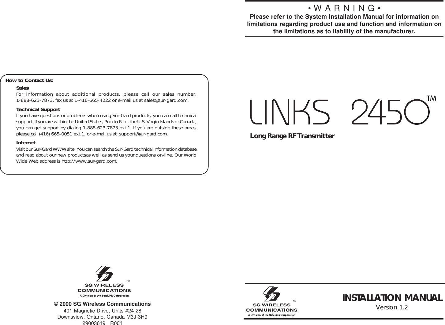
![21.2 AntennaNOTE: You must match the antennas to the frequency you will be using.The antenna for the LINKS2450 is not supplied. For optimum performance of theLINKS2450, use a quality antenna system, such as model SLA-532, available fromSafe Link Corporation. This 5/8 over 5/8 wave high performance antenna offersfeatures specifically designed for security radio installations.• 5db gain two-piece mast with center coil• Standard frequency range 440-470MHz• Ten feet of coax with BNC connector attached.To ensure proper operation, mount the antenna at least ten feet from the LINKS2450 unit. (See diagram below).15[83] Miscellaneous Alarm Reporting Codes(PC1555/1565 v2.0 panel only)Default = FFI_______I_______I Police CodeI_______I_______I Delinquency Code[96][Installer Code][96]Restore LINKS2450 Factory Default Programming for PC1575/1580[993][Installer Code][993]Restore LINKS2450 Factory Default Programming for PC5015v2.2, PC5010 v2.0, PC1555/1565 and PC580/585PC4010/4020 LINKS2450 Toggle OptionsProgram these options at a PC4010/4020 system keypad. See section 3.2 for moreinformation.Ref # [000405] LINKS 2XXX (use arrow keys (< >) to scroll to each option)Option DefaultLINKS 2XXX N (Y for CF panels)Alarm/Restore N (Y for CF panels)Open/Close N (Y for CF panels)All Others N (Y for CF panels)](https://usermanual.wiki/Tyco-Safety-Canada/00LINKS2450/User-Guide-127081-Page-5.png)
![3INSTALLING THE LINKS2450Section 2Before installing the LINKS2450, install and test the security system to which it willbe connected, according to the system’s Installation Manual.2.1 Unpacking the LINKS2450Check that each of these parts is included in your LINKS2450 package.•LINKS2450 circuit board•LINKS2450 plastic cabinetCAUTION: Due to the sensitivity of the RF circuitry, avoid any contact with the coilsand potentiometers on the LINKS2450 circuit board.2.2 Select a Mounting LocationThe area where you mount the LINKS2450 should be:• dry• close to the installed alarm control panel cabinet.• far from sources of interference, including: electrical noise such as computers,televisions and electric motors in appliances and heating and air conditioningunits; large metal objects like heating ducts and plumbing which may shield theantenna. If you must mount the LINKS2450 near such items, you may have tomount the antenna on a remote bracket away from the LINKS2450.• close to the power supply. See section 2.3 “Connect a Power Supply”.2.3 Connect a Power SupplyYou can use the Bell+ and Aux- terminals from the control panel to power theLINKS2450. If you will be using a separate power supply, install it near theLINKS2450. Refer to the power supply’s installation instructions, for more information.NOTE: The current drawn by the LINKS2450 and the siren(s) connected to the Bellterminals must not exceed that specified by the rating of the control panel. Refer toyour control panel’s Intallation Manual for more information.The wiring between the LINKS2450 and the power supply should not be longer thanindicated in the table below:Wire Gauge (AWG) Maximum Wire Length (feet / meters)22 15' / 4.5m20 25' / 7.5m18 40' / 12.0mYou can double the maximum wire length if you double the conductors and connectthem in parallel. Mount the LINKS2450 as close to the power supply as possible.14PROGRAMMING WORKSHEETS[01] Module ConfigurationDefault Option ON OFFON I_______I1Communications Communicationsenabled disabledOFF I_______I2Serial connection Keybus connection[10] LINKS2450 Account CodeDefaultFF FF I_______I_______I l_______I_______I Valid entries are 00-FFEnter two 2-digit hexadecimal numbers.[20] Maintenance Alarms and Restoral Reporting CodesDefault = FFI_______I_______I Keybus/Serial Fault AlarmI_______I_______I Keybus/Serial Fault RestoralI_______I_______I For future use[30] Call Direction Options (PC5015, PC5010, PC1575/1580and PC1555/1565 panels only)Default Option ON OFFONI_______I1Alarm/restore reporting enabled DisabledONI_______I2Tamper/restore reporting enabled DisabledOFFI_______I3Opening/closing reporting enabled DisabledONI_______I4System maintenance reporting enabled DisabledONI_______I5System test transmission reporting DisabledenabledOFFI_______I6-7For future use EnabledOFFI_______I8Future event Support Disabled[81] Miscellaneous Alarm Reporting Codes (PC1575/1580 panel only)Default = FFI_______I_______I General Zone Fault AlarmI_______I_______I General System Tamper AlarmI_______I_______I General System Supervisory Alarm[82] Miscellaneous Restoral Reporting Codes(PC1575/1580 panel only)Default = FFI_______I_______I General Zone Fault RestoreI_______I_______I General System Tamper RestoreI_______I_______I General System Supervisory Restore](https://usermanual.wiki/Tyco-Safety-Canada/00LINKS2450/User-Guide-127081-Page-6.png)
![42.4 Mount and Wire the LINKS24501. Run the panel wiring and the power supply wiring to the LINKS2450 mountinglocation.2. Remove the four screws that attach the LINKS2450 circuit board to theplastic cabinet.3. Pull all wires through the hole at the back of the cabinet.4. Mount the cabinet securely to the wall. Use the appropriate wall anchorswhen securing the panel to drywall, plaster, concrete, brick or similarsurfaces.5. Reattach the LINKS2450 into the mounted cabinet using the four mountingscrews.6. Find the antenna connection in the hole at the top of the cabinet. Secure theantenna to the LINKS2450 antenna connector.NOTE: Make sure an antenna is always connected to the LINKS2450 whenever itis operated. The unit will not work and may be damaged if an antenna is not in-stalled.7. Complete all wiring: If you will be connecting the LINKS2450 to a PC5015,PC5010, PC1575/1580, PC1555/1565 or PC580/585 panel, go to step 8a. Ifyou will be connecting the LINKS2450 to a PC4010 or PC4020 panel, go tostep 8b.8a. Connect the LINKS2450 according to diagram 2-2. Make sure jumper J3on the LINKS2450 is NOT shorted.8b. Connect the LINKS2450 to a PC2550RK keypad according to diagram 3-1. Make sure jumper J3 on the LINKS2450 IS SHORTED. When you havefinished programming, disconnect the power supply and the PC2550RKkeypad from the LINKS2450. Remove the short from jumper J3. Connectthe LINKS2450 to the control panel according to diagram 2-3.NOTE: Double-check all wiring to ensure that it is correct. Incorrect wiring connec-tions may cause the LINKS2450 to operate improperly, or may damage the unit.8. Connect the power: Connect the power terminals (VTX+ and VTX–) to a 11.5 -14VDC, 1A power supply.CAUTION: Do not connect the power supply until all other wiring, including theantenna connection, has been completed and checked to ensure that it is correct.13RESET LINKS2450 PROGRAMMING TO FACTORYDEFAULTSection 6If you need to reset the LINKS2450 to factory default programming, follow thedirections in the appropriate sections below.6.1 Reset the LINKS2450 on a PC1575/1580 PanelTo reset the LINKS2450 on a PC1575/1580 panel, enter [96] [Installer’s Code] [96].6.2 Reset the LINKS2450 on a PC5015 v2.2, PC5010 v2.0, PC1555/1565 or PC580/585 PanelTo reset the LINKS2450 on a PC5015 v2.2, PC5010 v2.0 or PC1555/1565 panel,enter [993] [Installer’s Code] [993].NOTE: This command is unavailable on PC5010 v1.0. If v1.0 is used, you mustperform a hardware reset (see section 6.3 below).6.3 Perform a Hardware Reset (All panels)To reset the LINKS2450 when connected to a PC5010 v1.0 or a PC4010/4020panel, you must perform a hardware reset. To do this:1. Remove all power from the LINKS24502. Short j umper J33. Remove all wires from the YEL and GRN terminals4. With a piece of wire, short the YEL terminal to the GRN terminal5. Apply power to the LINKS2450 for 5 seconds.6. Remove power from the LINKS24507. Reconnect all original wiring and re-power the LINKS2450NOTE: If the LINKS2450 is connected to a PC4010/4020 panel, the programmingdone in the panel software will not be reset. See section 3.2, step 5 for informationon re-programming the PC4010/4020 sections.](https://usermanual.wiki/Tyco-Safety-Canada/00LINKS2450/User-Guide-127081-Page-7.png)
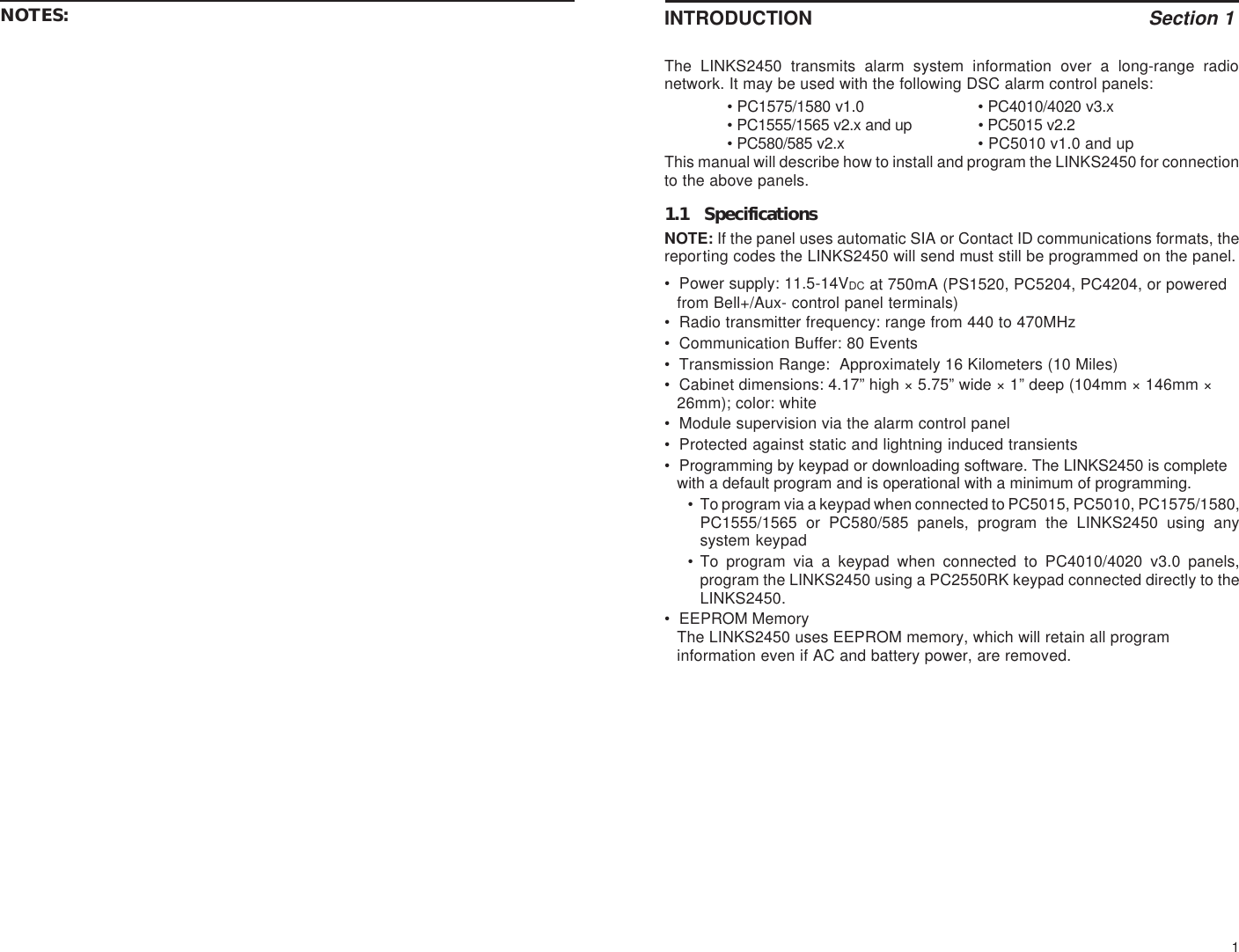
![5DIAGRAM 2-1Hook-up For PC5010, PC5015, PC1555/1565, PC1575/1580 orPC580/585 PanelsCAUTION: Due to the sensitivity of the RF circuitry, avoid any contact with the coilsand potentiometers on the LINKS2450 circuit board.*If power supply supervision is required for the LINKS2450 VTX terminals, use thePC5204. If no supervision is needed, you can use the PS1520 or the control panelBell+/Aux- terminals.NOTE: Programming section [01], option 2 must be OFF for LINKS2450 to workwith these panels.12TESTING THE LINKS2450Section 5Before testing the LINKS2450, ensure that the control panel is correctly pro-grammed and operating properly. Refer to your system Installation Manual forinstructions on testing your system. The control panel must be programmed properlyin order for the LINKS2450 to operate.To check that the LINKS2450 is working, apply power to the unit after all wiringconnections have been made. When the LINKS2450 is sending a transmission, theLED on the circuit board will turn on.5.1 Performing a LINKS Test TransmissionContact the monitoring station to request a transmission test. Remove the telephonecord from the RJ31-X jack. Perform a Bell Test as described in the control panel’sInstallation Manual. When the test is complete, contact the monitoring station toconfirm the transmission. Perform additional test transmissions as required by thecentral station.5.2 “On Air” IndicationWhenever the LINKS unit is communicating, the LED on the unit’s circuit board willturn ON for each round of communications. Each event has 3 rounds. Therefore, ifone reporting code is sent, the LED will activate 3 times to indicate each round.5.3 TroubleshootingIf the LINKS2450 is not working properly, check that all wiring and all programmingis correct before calling for technical support.5.4 Testing ToolsThe following tools are available from Safe Link:UHF RF Power Meter - Connects to the antenna jack on the LINKS2450. Indicatesthe transmit power of the radio.UHF Scanner - Checks that the radio is transmitting data.Frequency Counter - Checks that the LINKS2450 is transmitting on the correctfrequency.5.5 Periodic Test TransmissionThe LINKS 2450 will transmit a periodic test transmission at the time/day/intervalusing the Reporting code programmed in the main control panel.](https://usermanual.wiki/Tyco-Safety-Canada/00LINKS2450/User-Guide-127081-Page-8.png)
![6DIAGRAM 2-2Hook-up for PC4010/4020 v3.0 PanelsCAUTION: Due to the sensitivity of the RF circuitry, avoid any contact with the coilsand potentiometers on the LINKS2450 circuit board.*If power supply supervision is required for the LINKS2450 VTX terminals, use thePC4204. If no supervision is needed, you can use the PS1520 or the control panelBell+/Aux- terminals .NOTE: Programming section [01], option 2 must be ON for LINKS2450 to work withthese panels.11[81] Miscellaneous Alarm Reporting Codes(PC1575/1580 panel only)Program 2 digit reporting codes for the following:• General Zone Fault AlarmThis code will be sent when the LINKS2450 receives a General Zone FaultAlarm event from the PC1575/1580.• General System Tamper AlarmThis code will be sent when the LINKS2450 receives a General SystemTamper Alarm event from the PC1575/1580.• General System Supervisory AlarmThis code will be sent when the LINKS2450 receives a General SystemSupervisory Alarm event from the PC1575/1580.[82] Miscellaneous Restoral Reporting Codes(PC1575/1580 panel only)Program 2 digit reporting codes for the following (see your PC1575/1580 InstallationManual for more information):•General Zone Fault Restoral: This code will be sent when the LINKS2450receives a General Zone Fault Restoral event from the PC1575/1580.•General System Tamper Restoral: This code will be sent when theLINKS2450 receives a General System Tamper Restoral event from thePC1575/1580.•General System Supervisory Restoral: This code will be sent when theLINKS2450 receives a General System Supervisory Restoral event from thePC1575/1580.NOTE: Sections [81] and [82] apply to the PC1575/1580 only. All other panels willuse the reporting codes that are programmed for these events in the panel.[83] Miscellaneous Alarm Reporting Codes(PC1555/1565 v2.0 panel only)Program 2 digit reporting codes for the following (see your PC1555/1565 InstallationManual for more information):•Police Code: This code will be sent when the LINKS2450 receives a PoliceCode event from the PC1555/1565.•Delinquency Code: This code will be sent when the LINKS2450 receives aDelinquency event from the PC1555/1565.](https://usermanual.wiki/Tyco-Safety-Canada/00LINKS2450/User-Guide-127081-Page-9.png)
![7PROGRAMMING THE LINKS2450Section 3See section 3.1 for programming instructions when connecting the LINKS2450 toa PC5015, PC5010, PC1575/1580, PC1555/1565 or PC580/585 panel. See section3.2 for programming instructions when connecting the LINKS2450 to a PC4010 orPC4020 v3.0 panel.3.1 Programming a LINKS2450 Connected to a PC5015, PC5010,PC1575/1580, PC1555/1565 or PC580/585 Panel.Program the LINKS2450 through Installer’s Programming at a system keypad.For instructions on using Installer’s Programming sections, please refer toSection 4 “How to Program” in your control panel Installation Manual.1. Go to Installer’s Programming by entering [*][8][Installer’s code].2.For PC5015, PC5010, PC1555/1565 and PC580/585: Go to the LINKS2450programming section by entering [803]. Program the following sections only(see section 4 for a description of each section). Record your programmingchoices in the worksheets at the end of this manual.[01] Module ConfigurationOption 1: Communications Enabled / DisabledOption 2: Serial Connection / Keybus Connection[10] LINKS2450 Account Code[20] Maintenance Alarms and Restoral Reporting Codes[30] Call Direction Options[83] Miscellaneous Alarm Reporting Codes (PC1555/1565 v2.0 panel only)3. For PC1575/1580: Go to the LINKS2450 programming section by entering[86]. Program the following sections only. See section 4 for a description ofeach section. Record your programming choices in the worksheets at the endof this manual.[01] Module ConfigurationOption 1: Communications Enabled / DisabledOption 2: Serial Connection / Keybus Connection[10] LINKS2450 Account Code[20] Maintenance Alarms and Restoral Reporting Codes[30] Call Direction Options[81] Miscellaneous Alarm Reporting Codes (PC1575/1580 panel only)[82] Miscellaneous Restoral Reporting Codes (PC1575/1580 panel only)4. To exit Installer’s Programming, press [#].10PROGRAMMING DESCRIPTIONSSection 4[01] Module ConfigurationOption 1: Communications Enabled / DisabledEnable this option to have the LINKS2450 initiate communications for all events thathave reporting codes and call direction options (section [30]) programmed. Disablethis option to test the system.Option 2: Serial Connection / Keybus ConnectionEnable this option if you will use the LINKS2450 with a PC4010/4020 panel. Disablethis option if you will use the LINKS2450 with a PC5015, PC5010, PC1575/1580,PC1555/1565/1565 or PC580/585 panel.[10] LINKS2450 Account CodeThis 4-digit code is used to identify the system and is transmitted when theLINKS2450 initiates communications. Program a 4-digit code in this section using2 two-digit Hexadecimal numbers. Refer to your control panel Installation Manual forinstructions on programming hexadecimal digits.NOTE: An account number must be entered in this section before the LINKS2450can send any communications. Programming [FFFF] will disable the LINKS2450.[20] Maintenance Alarms and Restoral Reporting CodesProgram 2 digit reporting codes for the following:•Keybus/Serial Fault Alarm: This code will be sent when connection is lost tothe panel for more than 30seconds.•Keybus/Serial Fault Restoral: This code will be sent when connection isrestored to the panel for more than 30seconds.•For future use.[30] Call Direction Options (PC5015, PC5010, PC1575/1580, PC1555/1565 and PC580/585 panels only)Program which of the following reporting code types the LINKS2450 will send to thecentral station:• Alarm/restore reporting• Tamper/restore reporting• Opening/closing reporting• System maintenance reporting• System test transmission reporting• Future event supportIn most installations, you should program the tranmission of alarm/restorereporting codes only. Your radio network has limited bandwidth and capacity. Themore signals each LINKS2450 transmits, the fewer LINKS2450s you will be able toinstall on your network.The Future Event Support option refers to reporting codes (events) that may beadded to future software versions of DSC control panels. If you turn on the FutureEvent Support option, when the new events occur, the LINKS2450 will sendreporting codes for the events to the central station. If you do not turn this option on,the LINKS2450 will not send reporting codes for events that are not currentlyincluded in one of the call direction groups.](https://usermanual.wiki/Tyco-Safety-Canada/00LINKS2450/User-Guide-127081-Page-10.png)
![83.2 Programming a LINKS2450 for Use with a PC4010/PC4020 v3.0or higher panel.There are two stages in programming the LINKS2450 for a PC4010 or PC4020 panel:1. Program the LINKS2450 programming sections from a PC2550RK keypadconnected directly to the LINKS2450.2. Program the LINKS2450 toggle options on the PC4010/4020 control panel.Program the LINKS2450 from a PC2550RK Keypad:1. Make sure the LINKS2450 is connected to a PC2550RK keypad (refer todiagram 3-1). Make sure that jumper J3 is shorted.2. Program the following sections only. Other programming sections are notrelevant to PC4010/4020 panels. See section 4 for a detailed description ofthese sections.Enter the two-digit number for each section you want to program, then, enter thedata required to complete the section programming. If you enter information intoa section and make a mistake, press [#] to exit the section. Select the sectionagain, and re-enter the information correctly.Record your programming choices in the worksheets at the end of this manual.[01] Module ConfigurationOption 1: Communications Enabled / Disabled. Press [1] to alternatelyenable or disable the option.Option 2: Serial Connection (Enabled) / Keybus Connection (Disabled).Press [2] to alternately enable or disable the option.[10] LINKS2450 Account Code. Enter 2 two-digit hexadecimal numbers.Refer to your Installation manual for information on Hexadecimalprogramming.[20] Maintenance Alarms and Restoral Reporting Codes. Enter two hexa-decimal digits for each code.3. When you have finished programming the above sections, disconnect thepower and the PC2550RK keypad.4. Connect the LINKS2450 to the panel as in diagram 2-2.Diagram 3-1Connecting the LINKS2450 to aPC2550RK Keypad9Program the LINKS2450 Toggle Options on the PanelAt a PC4010 or PC4020 system keypad, enter reference # [000405] and [*], or scrollto the “LINKS2XXX” programming section. (See the “How to Program” section in yourPC4010/4020 Installation Manual for more information.) Use the arrow keys (< >) toscroll to each of the following toggle options. Press [*] to toggle the option ON or OFF.Record your programming choices in the worksheets at the end of this manual.LINKS 2XXX Yes When enabled the PC4010 or PC4020 will send the eventsthat are programmed to the LINKS 2450. The PC4010/4020 will only send the events that have reporting codesprogrammed and dialer directions enabled for them.No The PC4020 will not send events to the LINKS2450.Default condition is No.NOTE: The Communications Toggle option “Comms Enabled” must also be set toYes for the PC4010/4020 to be able to send events to the LINKS 2XXX.To disable the PC4010/4020 telephone communications, but still allow the PC4010/4020 to communicate events through the LINKS 2XXX, set “Comms Enabled” toYes, and the Dialer Directions to No for all 3 telephone numbers. Leaving all 3telephone numbers unprogrammed will also disable telephone communications.See the “Communications Programming” section in your PC4010/4020 InstallationManual for more information.Alarm/Restore Yes Alarm and Restoral reporting codes are sent to the centralstation by the LINKS2450.No Alarm and Restoral reporting codes are not sent to theLINKS2450.Default: No (Yes on PC4010CF/4020CF panels)Open/Close Yes Opening and Closing reporting codes are sent to thecentral station by the LINKS2450.No Opening and Closing reporting codes are not sent to theLINKS2450Default: No (Yes on PC4010CF/4020CF panels)All others Yes All other reporting codes are sent to the central station bythe LINKS2450.No All other reporting codes are not sent to the LINKS2450Default: No (Yes on PC4010CF/4020CF panels)To exit the LINKS2XXX programming section, press [#].Program Panel Supervision for the LINKS2450Panel supervision of the LINKS2450 is recommended when connected to PC4010/4020 panels. To have the panel supervise the LINKS2450, make sure the zone thatthe LINKS2450 is connected to on the panel is programmed for LINKS Supervisory(zone type [28]). When the zone is programmed this way, if the YEL terminal is notgrounded (e.g. the wire is cut), the panel will generate a zone trouble and a LINKStrouble and will send the reporting code for the zone.See your PC4010/4020 Installation Manual for information on zone programming.](https://usermanual.wiki/Tyco-Safety-Canada/00LINKS2450/User-Guide-127081-Page-11.png)