Tyco Safety Canada 00SS5501Z32 Spread Spectrum Receiver User Manual LCD5501Z32 900 im um all en 29005015 r001
Digital Security Controls Ltd. Spread Spectrum Receiver LCD5501Z32 900 im um all en 29005015 r001
UserManual.wiki
>
Tyco Safety Canada
>
00SS5501Z32 User Manual
Installation manual
Navigation menu
Upload a User Manual
Namespaces
Wiki Guide
HTML
PDF
Info
Views
User Manual
Discussion / Help
Navigation


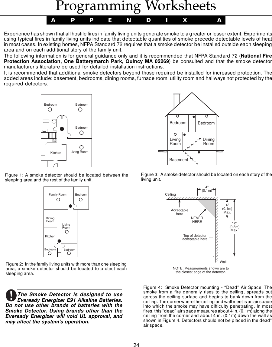
![3Enter the following at each keypad installed on thesystem:1. Enter Installer Programming by pressing[*][8][Installer’s Code]2. Press [000] for Keypad Programming3. Press [0] for Partition and Slot Assignment4. Enter a two digit number to specify the partitionand slot assignment.NOTE: If your system does not have partitions,enter [1] for the first digit.1st digit Enter 0 for Global KeypadEnter 1 for Partition 1 KeypadEnter 2 for Partition 2 Keypad2nd digit Enter 1 to 8 for Slot Assignment5. Press the [#] key twice to exit programming.6. After assigning all keypads, perform a supervisoryreset by entering [*][8][Installer’s Code][902]. Thepanel will now supervise all assigned keypadsand enrolled modules on the system.To review which modules the controlpanel is currently supervising:1. Enter [✱][8][Installer’s Code]2. Enter [903] to display all modules. On theI N S T A L L A T I O NLCD5501Z32-900 keypad, 11111 and 1111177777 will scroll onthe keypad to indicate that the LCD5501Z32-900 ispresent on the system. 11111 designates the keypadsection, and 1717171717 is used to show the receiversection is also supervised. On the LCD5500Zkeypad, scroll until the module name appears onthe display.3. To exit press [#].If both modules do not show on the keypad, one ofthe following conditions may be present:• the keypad is not connected properly to the Keybus• there is a problem with the Keybus wiring run• the keypad does not have enough power](https://usermanual.wiki/Tyco-Safety-Canada/00SS5501Z32/User-Guide-88429-Page-6.png)
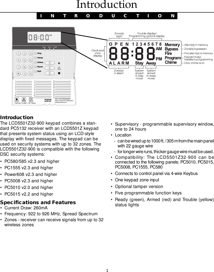
![42.1 Programming the KeypadThere are several programming options availablefor the LCD5501Z32-900 keypad. These aredescribed below. Record all your programmingchoices in the programming worksheets included inthis manual.Programming the LCD5501Z32-900 is similar toprogramming the rest of the system. When you are inthe LCD5501Z32-900 programming sections, thekeypad will display which options are turned on alongthe top of the display. To turn an option on or off, pressthe number corresponding to the option on thenumber pad. The numbers of the options that arecurrently turned ON will be displayed.For example, if options 1 and 2 are on, the displaywill look like:For information on programming the rest of yoursecurity system, please refer to your system’sInstallation Manual.2.2 Function Key OptionsThe function keys are programed in sections [1] to[5]. By default, the 5 function keys on the keypad areprogrammed as Stay Arm (03), Away Arm (04),Chime (06), Sensor Reset (14) and Quick Exit (16).You can change the function of each key on everykeypad. Please see your system’s InstallationManual for instructions on programming the keys,and a complete list of all the function key optionsavailable for your system.2.3 Clock OptionsThe LCD5501Z32-900 will display the current timeafter 30 seconds of no key presses. To set thecorrect time and date for the system, please refer toyour system’s Instruction Manual. You can changehow the keypad displays the time with the followingoptions. To change the clock options:1. Enter [*][8][Installer’s code]2. Enter [000] to go to keypad programming3. Enter section [6] to go to clock options.4. To turn any of the options on or off, press [1], [2], or [3]:NOTE: If the Time does not display on keypad optionis selected, make sure that the Keypad displays timewhen zones are open option is also selected.[1] ON = Time displays on keypadOFF = Time does not display on keypad[2] ON = Clock display is in AM/PM format(e.g. 08:00 AM)OFF = Clock display is in 24-hour format(e.g. 20:00)[3] ON = Keypad does not display timewhen zones are openOFF = Keypad displays time when zonesare open5. When you are finished programming the clockoptions, press [#] to exit.Keypad ProgrammingS E C T I O N 2](https://usermanual.wiki/Tyco-Safety-Canada/00SS5501Z32/User-Guide-88429-Page-7.png)
![52.4 Alarms Displayed While ArmedOptionYou can disable the display of alarms on thekeypad when the system is armed. The display ofalarms is enabled by default. To disable the displayof alarms when the system is armed, turn offsection [6], option [5]:1. Enter [*][8][Installer’s code]2. Enter [000] to go to keypad programming3. To turn the display of alarms on or off, enter section[6].4. Turn option [5] on or off:[5] ON = Alarms not displayed while system isarmedOFF = Alarms are always displayed whilesystem is armed5. When you are finished, press [#] to exit.2.5 Emergency (Fire, Auxiliary,Panic) Key OptionsYou can enable or disable the Fire, Auxiliary andPanic keys at each keypad. These keys areenabled by default. Please see your system’sInstallation Manual for more information on thesekeys and their options. To turn any of the emer-gency keys on or off on the keypad:1. Enter [*][8][Installer’s code]2. Enter [000] to go to keypad programming3. Enter section [7].4. To turn the emergency key options on or off, press[1], [2], or [3]:[1] ON = Fire key enabledOFF = Fire key disabled[2] ON = Auxiliary key enabledOFF = Auxiliary key disabled[3] ON = Panic key enabledOFF = Panic key disabled5. When you are finished, press [#] to exit.2.6 Door Chime OptionsYou can program the LCD5501Z32-900 keypad tosound a tone when any zone is opened or closed.There are two parts to the LCD5501Z32-900 doorchime programming:• Program if the LCD5501Z32-900 will chime whenzones are opened and/or closed.• Program the type of sound the LCD5501Z32-900 willmake when an individual zone is opened or closed.For the door chime feature to work, you will also needto turn on the Door Chime attribute for each zone thatwill trigger the chime. This programming is done in thecontrol panel software. Refer to your control panel’sInstallation Manual for more information.Door Chime on Zone Openings/ClosingsYou can program each LCD5501Z32-900 keypad tosound a door chime when zones are opened and/orwhen they are closed. By default, LCD5501Z32-900keypads are programmed to sound door chimes onboth zone openings and closings.To change the door chime opening/closing settings,at each LCD5501Z32-900 keypad:1. Enter [*][8][Installer’s code]2. Enter [000] to go to keypad programming3. Enter section [6].4. To turn the options on or off, press [6] or [7]:[6] ON = Door Chime Enabled for ZoneOpeningsOFF = Door Chime Disabled for ZoneOpenings[7] ON = Door Chime Enabled for ZoneClosingsOFF = Door Chime Disabled for ZoneClosings5. When you are finished, press [#] to exit.K E Y P A D P R O G R A M M I N G](https://usermanual.wiki/Tyco-Safety-Canada/00SS5501Z32/User-Guide-88429-Page-8.png)
![6Door Chime SoundsYou can program the LCD5501Z32-900 keypad tomake different door chime sounds for individualzones, or groups of zones. Each LCD5501Z32-900keypad can make any of four door chime soundsfor each zone that triggers the door chime:· 4 quick beeps (default sound)· ‘Bing – Bing’ tone· ‘Ding – Dong’ tone· ‘Alarm’ toneNOTE: For a zone to be able to trigger the door chimesound, the Door Chime zone attribute must also beenabled in the control panel programming. Please seeyour control panel Installation Manual.To change the door chime sounds:1. Enter [*][8][Installer’s code].2. Enter [*] to go to door chime sound programming.3. Enter a 2-digit number for the zone you want toprogram [01] - [32].4. Turn one of the following options on by pressing[1], [2], [3], or [4]:[1] 4 quick beeps (default sound)[2] ‘Bing – Bing’ tone[3] ‘Ding – Dong’ tone[4] ‘Alarm’ toneK E Y P A D P R O G R A M M I N GNOTE: Make sure that only one of the above optionsis turned on. If more than one is on, the keypad willsound the first option that is enabled. If none of theoptions are selected, the keypad will not make anysound when the zone is opened or closed.5. To program the door chime sound for anotherzone, repeat steps 3 and 4.6. When you are finished programming the doorchime sounds, press [#] to exit.](https://usermanual.wiki/Tyco-Safety-Canada/00SS5501Z32/User-Guide-88429-Page-9.png)
![7 Receiver ProgrammingS E C T I O N 33.2 Enroll Wireless Devices UsingZones (WLS904, WLS905, WLS906,WLS907, WLS908 and WLS915)Enroll wireless devices which use zones (universaltransmitters, motion detectors, smoke detectors, andpanic pendants):1. At a system keypad, enter [✱][8][Installer’s code]to go the installer’s programming section.2. Enter programming section [804].3. Enter the 2-digit number corresponding to thezone the device is to occupy ([01] to [32]).NOTE: Hardwired and wireless devices cannot beassigned to the same zone. PC5108 zone expandermodules occupy zones in 2 groups of 4 (e.g. zones9-12 and zones 13-16). None of the zones assignedto a PC5108 module may be used for wirelessdevices. For more information on zone assignment,consult your system Installation Manual.4. Enter the device’s ESN. The entry must be sixdigits. If an older device with a 5-digit ESN is beingenrolled, add the digit [0] to the beginning of theESN. (E.g. ESN=21234, enter 021234)5. The device is now enrolled on the system. Recordthe serial number and the assigned zone numberin the programming worksheets in the back of thismanual.6. Continue with steps 3 - 5 until you have enrolledall wireless devices.7. To exit press [#].NOTE: The devices will not work properly until youcomplete zone and partition programming (seesection 4).Enroll & Program DevicesThis section describes how to enroll and program:• wireless devices using zones (WLS904, WLS905,WLS906, WLS907, WLS908, and WLS915)• wireless keys (WLS909)• handheld keypads (WLS910).For more information on these devices, read theinstruction sheet included with each device.3.1 A Note about Electronic SerialNumbersAn electronic serial number (ESN) is printed on theback of each wireless device. ESNs are used to enrollthe wireless devices with the LCD5501Z32-900keypad.In order to reduce the occurrence of wirelessdevices with the same serial number, 6-digit serialnumbers are now printed on the back of eachwireless device.NOTE: 6-digit serial numbers are only supported onthe following control panels: PC5010 v2.x and higher,PC5015 v2.2, PC5008, PC1555 and PC580.The 6-digit serial numbers include hexadecimal digits.For instructions on programming hexadecimal numbers,see your system Installation Manual, section 4: How toProgram.When connecting the LCD5501Z32-900 to a PC5010 orPC5015 v1.x panel, enter 5-digit serial numbers only.When connecting the LCD5501Z32-900 to a PC5010v2.x, PC5015 v2.x, PC5008, PC1555 or PC580 panelfollow the instructions below.Old Wireless Device ESNsYou can use older devices on all versions of theLCD5501Z32-900 keypad, even though they only havea 5-digit ESN. When using older wireless devices:EEEEEnter [0] + 5-digit ESNnter [0] + 5-digit ESNnter [0] + 5-digit ESNnter [0] + 5-digit ESNnter [0] + 5-digit ESN](https://usermanual.wiki/Tyco-Safety-Canada/00SS5501Z32/User-Guide-88429-Page-10.png)
![8E N R O L L & P R O G R A M D E V I C E S3.3 Enroll & Program Wireless Keys(WLS909)For wireless keys to work on the system, you need toenroll them and then program the function buttons.Wireless keys are not assigned to zones and requireno zone programming. You can enroll up to 16wireless keys on the system.Enroll Wireless keys1. At a system keypad, enter [✱][8][Installer’s code]to go to the Installer’s Programming section.2. Enter programming section [804].3. Enter a 2-digit number [41]-[56] to assign thewireless key a slot. These numbers correspondto wireless key numbers 01-16.4. Enter the key’s ESN. The entry must be six digits.If an older key with a 5-digit ESN is being enrolled,add the digit [0] to the beginning of the ESN. (E.g.ESN=61234, enter 061234)5. The key is now enrolled on the system. Recordthe serial number and the assigned slot numberin the programming worksheets in the back of thismanual.6. Repeat steps 3 - 5 until all wireless keys havebeen enrolled.7. (PC5010 and PC5015 only)(PC5010 and PC5015 only)(PC5010 and PC5015 only)(PC5010 and PC5015 only)(PC5010 and PC5015 only) By default, allwireless keys are assigned to Partition 1. To assignkeys to Partition 2, enable the appropriate optionsin programming sections [91] and [92].NOTE: A wireless key can only be assigned to onepartition.8. To exit press [#].Program the WLS909 Function ButtonsWLS909 wireless keys have four programmablefunction buttons. You must program a set of fourfunctions for the buttons before any keys will work.After the functions are programmed, when you pressand hold one of the four buttons for two seconds, thesystem will execute the programmed function.For systems not using partitions: program thefunction buttons in section [59]. All wireless keys willhave the same four functions.For systems using 2 partitions (PC5010 andPC5015 only): all wireless keys assigned to Partition1 will have the four functions programmed in section[59]. All wireless keys assigned to Partition 2 willhave the four functions programmed in section [60].For example, if function button 1 in Section [59] isprogrammed for Stay arming, then pressing the firstbutton on wireless keys assigned to Partition 1 willStay arm Partition 1.NOTE: Wireless keys will not work when the partitionthey are assigned to is being accessed for zonebypassing or programming.1. At a system keypad, enter [✱][8][Installer’s code].2. Enter programming section [804].3. Enter programming section [59] for keys assignedto partition 1, or [60] for keys assigned to partition 2.4. For each of the 4 function buttons, enter the 2-digit number of the function you want to select.See the programming worksheets for a list offunction key options.5. Record your programming choices in theworksheets in the back of the manual.6. To exit press [#].3.4 Identified Wireless KeysReporting by the system of openings/closings byindividual wireless keys and command output[Q][7] activation by wireless key buttons may besupported on certain control panels. To do this, thesystem will reserve access codes 17 – 32 forwireless keys 01-16 respectively. You must programone access code for each wireless key (using[Q][5] access code programming) for this feature towork correctly.Refer to your system Installation Manual forinformation on access code programming.](https://usermanual.wiki/Tyco-Safety-Canada/00SS5501Z32/User-Guide-88429-Page-11.png)
![9Opening/Closing By Wireless KeyReportingNOTES: The Identified Wireless Key Closing option isonly available with the PC5010 v2.0, PC5008 v2.0 andhigher by turning section [015] option 4 off.The Identified Wireless Key Opening option is onlyavailable with the PC1555 v2.1, PC580 v2.1, PC5008v2.1 and higher, PC5015 v2.2 and higher by turningsection [017] option 1 off.To enable the reporting of closings by identifiedwireless keys:• Make sure the control panel is v2.0 or higher• Program a valid access code for each key• Program a closing reporting code for each key’saccess code• Disable the Quick Arm option in section [015]option [4]To enable the reporting of openings by identifiedwireless keys:• Make sure the control panel is v2.1 or higher• Program a valid access code for each key• Program an opening reporting code for each key’saccess code• Enable the WLS Key Uses Access Codes byturning section [017] option [1] off.Command Output ActivationNOTE: The Identified Wireless Key Command OutputActivation feature is only available with the PC5010,PC5015, PC5008, PC1555 and PC580 v2.0 andhigher.To enable command output activation by wirelesskeys, ensure that:• Make sure the control panel is v2.0 or higher• Program a valid access code for each key• Enable the PGM output attribute Requires AccessCode for each PGM output programmed as[✱][7][1-4] in sections [141] to [154].3.5 Enrolling & ProgrammingHandheld Keypads (WLS910)For handheld keypads to work on the system, youneed to enroll them and then program the functionbuttons. You can enroll up to 4 handheld keypads onthe system.Enroll Handheld Keypads1. At a system keypad, enter [✱][8][Installer’s code]to go to the Installer’s Programming section.2. Enter programming section [804].3. Enter a 2-digit number (33-36) to assign thehandheld keypad a slot. These numberscorrespond to handheld keypad numbers 1-4.4. Enter the keypad’s ESN. The entry must be sixdigits. If an older keypad with a 5-digit ESN isbeing enrolled, add the digit [0] to the beginningof the ESN. (E.g. ESN=21234, enter 021234)5. The keypad is now enrolled on the system. Recordthe serial number and the assigned slot numberin the programming worksheets in the back of thismanual.6. Repeat steps 3 - 5 until all handheld keypads havebeen enrolled.7. (PC5010 and PC5015 only) By default, allhandheld keypads are assigned to Partition 1. Toassign a keypad to Partition 2, enable theappropriate options in programming section [90].NOTE: A handheld keypad can only be assigned toone partition.8. To exit press [#].Program the WLS910 Function ButtonsWLS910 handheld keypads have four programmablefunction buttons. You must program a set of fourfunctions for the function buttons to work.For systems not using partitions: program thefunction buttons in section [57]. All handheld keypadbuttons will have the same four functions.E N R O L L & P R O G R A M D E V I C E S](https://usermanual.wiki/Tyco-Safety-Canada/00SS5501Z32/User-Guide-88429-Page-12.png)
![10For systems using multiple partitions: i.e. allhandheld keypads assigned to Partition 1 will havethe four functions programmed in section [57]. Allhandheld keypads assigned to Partition 2 will havethe four functions programmed in section [58]. Forexample, if function button 1 in Section [57] isprogrammed for Stay arming, then pressing the firstbutton on handheld keypads assigned to Partition 1will Stay arm Partition 1.1. At a system keypad, enter [✱][8][Installer’s code]to go to the Installer’s Programming section.2. Enter programming section [804].3. Enter programming section for partition 1 functionbuttons, or for partition 2 function buttons.4. For each of the 4 function buttons, enter the 2-digit number of the function you want to select.See the programming worksheets for a list offunction button options.5. Record your programming choices in theworksheets in the back of the manual.6. To exit press [#].E N R O L L & P R O G R A M D E V I C E S3.6 Deleting Wireless DevicesTo remove a wireless device from the system, followthe guideline for adding a wireless device. Programthe ESN as [000000]. The wireless device for thezone will be removed.NOTE: You may need to remove power from the panelin order to clear troubles caused by deleted zones.Now that you have enrolled all the wireless devices,you will need to program the system to work properlywith the devices. See section 4 for more information.](https://usermanual.wiki/Tyco-Safety-Canada/00SS5501Z32/User-Guide-88429-Page-13.png)
![114.1 Program Zones and PartitionsNow that you have enrolled the wireless devices, youshould complete all zone programming on the system.Although the exact programming required variesdepending on which control panel the LCD5501Z32-900 is connected to, you should check that thefollowing programming areas are completed correctlyfor each wireless zone:• Enable zones and/or assign zones to one or morepartitions (programming sections [201]-[209]).• Program the definition for each zone (programmingsections [001]-[004]).NOTE: WLS906 wireless smoke detectors must beassigned to zones defined as Delay 24-hr fire(wireless) [87] or Standard 24-hr fire (wireless) [88]for proper supervision.• Enable the wireless zone attribute for each wirelesszone (PC585, PC1565, PC5008, PC5010 v2.0 andup, PC5015 v2.2 and up only) (programmingsections [101]-[132]).See your system Installation Manual, for moreinformation on each of the above programmingsections.4.2 Enable Receiver SupervisionThe control panel will automatically supervise thereceiver via the Keybus one-minute after at least onedevice has been enrolled on the module. The systemwill generate a General System Supervisory troubleif the module is removed from the Keybus. If you needto remove the LCD5501Z32-900 from an existingsystem, you will have to disable supervision of thePC5132.4.3 Enable Supervision of WirelessZonesNOTE (for PC5010 v1.x control panels only): For ULListed installation, Double EOL resistors must be ena-bled in the PC5010 for the wireless zones to be su-pervised. If normally Closed or Single EOL resistorsare selected the PC5010 will not be able to supervisethe wireless devices. If a wireless device stopsS E C T I O N 4Other Programmingsending a supervisory signal (the unit stops function-ing) the panel will not indicate a supervisory troublecondition unless Double EOL resistors are used. Inaddition, all hardwire zones must be wired for Dou-ble EOL resistors. For more information, refer to yourPC5010 v1.x Installation Manual.NOTE (PC5010 v2.0 and higher, PC5015 v2.2 andhigher, PC5008, PC1555, PC580 only): For wirelesssupervision to work, you must enable the wirelesszone attribute on all wireless zones (sections [101]to [132], option [8] ON).NOTE: The RF Jam Detect zone must have thesupervision option disabled.NOTE: The supervisory option for any panic pendantsenrolled on the system must be OFF. For UL Listedsystems, the wireless zones must be programmedas supervised.Wireless Supervisory WindowEach wireless zone (WLS904, WLS905, WLS906,WLS907 or WLS915) will send a supervisory signal every12 minutes. If the receiver does not receive a signalwithin the time programmed for the Wireless SupervisoryWindow, it will generate a supervisory fault.To program the wireless supervisory window:1. Enter [✱][8][Installer Code] to enter InstallerProgramming.2. Enter [804] to enter into Receiver Programming.3. Enter sections [81].4. Enter the time period for the supervisory window(valid entries are 01-24 hours).5. To exit press [#].WLS908 Panic PendantThe panic pendant does not transmit a supervisorysignal. This is so that the user will be able to take it awayfrom the premise. You must disable wireless supervi-sion for each zone in which a panic pendant is assigned.](https://usermanual.wiki/Tyco-Safety-Canada/00SS5501Z32/User-Guide-88429-Page-14.png)
![12O T H E R P R O G R A M M I N GDisable/Enable Zone SupervisionAll wireless zones have supervision enabled bydefault. To disable supervision for any zone, enterthe following at any system keypad:1. Enter [✱][8][Installer Code] to enter InstallerProgramming.2. Enter [804] to enter the PC5132 ModuleProgramming.3. Enter sections [82], [83], [84] and [85]. Disableor enable supervision for each wireless zone byturning each relevant option on or off.4. To exit press [#].4.4 RF Jam Detect ZoneFor RF jamming detection to work, you must select anunused zone to be used as the RF Jam Detect zone.When the receiver detects an attempt to jam the RFsignal, the RF Jam Detect zone will be violated andthe system will generate a tamper signal. When thejamming signal is gone, the RF Jam Detect zonecloses and the system sends a tamper restore signal.To enable RF jamming detection:1. Enter [✱][8] [Installer’s Code].2. Enter programming section [804].3. Select an unused zone to be the RF Jam Detectzone. Enter the 2-digit number ([01] to [32]) ofthe RF Jam Detect zone on the keypad, thenprogram the serial number as [200000].3. Enter section [93]. Enter the 2-digit number of theRF Jam Detect zone ([01] to [32]) in theprogramming section.4. Disable supervision for the RF Jam detect zoneby turning the relevant option off in section [82],[83], [84] or [85]. (See section 4.3 for moreinformation.)5. RF jamming detection is now enabled. To exitInstaller programming, press [#].4.5 Receiver Software DefaultReturning the receiver programming to factory defaultsettings is a quick way to remove all the enrolleddevices from the system and reset all theprogramming in section [804].NOTE: Performing this procedure will not change anyprogramming sections except [804]. Resetting thecontrol panel to factory default settings will not re-turn the PC5132 to factory default settings.To restore the PC5132 programming to the factorydefault settings, perform the following:1. Enter [✱][8] [Installer’s Code].2. Enter programming section [996].3. Enter the Installer’s Code, followed by [996] again.Press [#]. The software for the receiver sectionwill be restored to its factory default settings.4. Press [#] to exit Installer Programming. After asoftware default, you must exit and then re-enterInstaller Programming before attempting toprogram the receiver section.For instructions on restoring the default programmingof the control panel or any other connected module,see your system Installation Manual.](https://usermanual.wiki/Tyco-Safety-Canada/00SS5501Z32/User-Guide-88429-Page-15.png)
![13S E C T I O N 5Testing & Mounting5.1 Test the placement of WLS904,WLS905, WLS906, WLS907, andWLS915 devicesIt is very important to test the proposed placement ofeach wireless device before it is mounted. Followingthese steps will test the placement of the wirelessmotion detectors (WLS904), wireless smoke detectors(WLS906) and wireless door/window contacts (WLS905,WLS907, WLS915), based on the signal strength be-tween the LCD5501Z32-900 and the device.NOTE: You cannot test the Panic Pendant (WLS908),Wireless Key (WLS909), and Handheld Keypad(WLS910) in this mode. See section 5.2 for instructionson testing these devices. You cannot run a placementtest on the RF Jam Detect zone.1. Temporarily place the device you want to test inthe place you want to mount it.2. At a system keypad, enter [✱][8][Installer Code].3. Enter programming section [904].4 Enter the 2-digit zone number for the device tobe tested.5. Activate the device being tested until a result isdisplayed on the keypad or sounded by thekeypad or bell.WLS904: Remove the detector from its backplate,wait for 1-2 seconds, then reattach the detectorto its backplate.WLS906: Remove the detector from its backplate,wait for 5 seconds, then reattach the detector toits backplate. Or hold a magnet near the raisedline on the outer rim. Then remove the magnet.WLS905, WLS907 & WLS915: Open and closethe contact by moving the magnet away from theunit. If the unit is attached to a door or a window,open and close the door or window to activatethe device.6. Read the test results at the keypad:Result LED Keypad LCD Keypad Buzzer/BellGood Light 1 On Steady “Good” 1 Beep/SquawkFair Light 2 On Steady “Fair” 2 Beeps/SquawksBad Light 3 On Steady “Bad” 3 Beeps/SquawksActivate the device until you get 3 good or fair resultsin a row. Wait 10 seconds between each test on thesame device.You may mount wireless devices where results weregood or fair.Devices indicating a bad result must be moved toanother location. You may only have to move thedevice a few inches to correct a bad result.NOTE: Do not mount any device where a “bad” testresult was indicated.If several wireless devices produce BAD testresults, you may need to move the LCD5501Z32-900 to a better location.7. To test another device, press [#] once, thenrepeat steps 4 - 6. Continue to test the devicesuntil both the LCD5501Z32-900 and the devicesare in good locations.8. To exit installer programming, press [#] twice.5.2 Test WLS908, WLS909 andWLS910 ReceptionThe panic pendant (WLS908), wireless key (WLS909)and handheld keypad (WLS910) cannot be tested usingthe module placement test described above. To ensurethat the LCD5501Z32-900 is receiving transmissionsfrom these devices, conduct the following tests:WLS908: Activate the Panic alarm at several differentpoints in the installation.WLS909: Use the function keys to arm and disarmthe system at several different points in the installation.WLS910: Use the keypad to arm and disarm thesystem from several different points in the installation.If these devices do not operate from all points in theinstallation, you will need to move the LCD5501Z32-900 receiver. Moving the LCD5501Z32-900 higherwill usually improve the reception.](https://usermanual.wiki/Tyco-Safety-Canada/00SS5501Z32/User-Guide-88429-Page-16.png)
![14T E S T I N G & M O U N T I N GIf you move the LCD5501Z32-900, repeat the testsdescribed in sections 5.1 and 5.2 on all the wirelessdevices. Continue to test the devices until youhave found satisfactory locations for theLCD5501Z32-900 and the WLS904, WLS905,WLS906 and WLS907 devices, and there is goodreception between the LCD5501Z32-900 and theWLS908, WLS909 and WLS910 devices.Mount the WLS904, WLS905, WLS906,WLS907, and WLS915 DevicesIf you have conducted the placement test describedin section 5.1 and got 3 “Good” or “Fair” results in arow for each device, you can mount the wirelessdevices. See the Installation sheet for each devicefor mounting instructions.5.3 Battery Test for WLS908 PanicPendantsYou cannot test Panic Pendant batteries using themethods described in sections 5.1 and 5.2. You mustprogram panic pendant zones before you can testthe panic pendants.NOTE: If a low battery condition is detected, you mustimmediately replace the unit.Follow these steps to test panic pendants:1. Begin testing when your system is in the readystate and the keypad Ready light is on.2. Go to an LCD keypad.NOTE: If your system is partitioned, you can only viewthe Panic Pendant test result on a partition LCDkeypad. To view the test result on a global LCD key-pad, you must “loan” the keypad to the partition beforeyou begin the test. See your Installation Manual forinformation on global and partition keypads.3. Press and hold the “Test” button on the pendantfor two seconds.4. If the pendant’s battery condition is normal, theReady light on the LCD keypad will turn OFF for30 seconds or until the [#] key is pressed. On thePC5010, PC5015, PC5008, PC1555 and PC580v2.x or higher: If the pendant’s battery conditionis normal, the keypad will beep and the LCDkeypad will display “System Test in Progress.”If the pendant’s battery is low, the LCD keypad’sTrouble light will turn ON and the keypad will givea series of continuous beeps.Instruct the user(s) to perform this test when theyperform the weekly system test.NOTE: If a low battery condition is detected, you mustimmediately replace the unit.Replacing a Pendant with a LowBatteryYou should immediately replace a pendant when alow battery is indicated. To replace a pendant on thesystem, follow these steps:From the keypad:1. Enter [✱][8][Installer Code].2. Enter programming Section [804].3. Enter the 2-digit zone number of the pendant tobe replaced (01-32).4. Enter serial number [000000].5. Re-enter the 2-digit zone number for the pendantbeing replaced.6. Enter the ESN of the new pendant.7. To exit press [#] twice.Through downloading:1. Connect to the control panel throughdownloading.2. Upload window contents of the zone serialnumbers in the wireless expansion section ofdownloading.3. Change the serial number of the pendant to bereplaced to [000000].4. Download window contents.5. Enter the ESN of the new pendant.6. Download window contents.](https://usermanual.wiki/Tyco-Safety-Canada/00SS5501Z32/User-Guide-88429-Page-17.png)
![15S E C T I O N 6Additional Notes6.1 Trouble ConditionsThe control panel always watches for possible troubleconditions. If a trouble condition occurs, the keypad“Trouble” light will turn on and the keypad will beep.Press [✱][2] to display the trouble conditions.The following trouble conditions apply to thereceiver portion (identified as the PC5132 by thepanel) and/or any enrolled devices. For adescription of all troubles, please see your systemInstallation Manual.• General System Tamper• General System Supervisory• Zone Fault• Device Low Battery• Zone TamperWireless Zone Low BatteryTransmissionWithin the supervisory transmission, the device willindicate the status of the battery. If a battery is low,the system will indicate a Device Low Battery trouble.NOTE: Since the WLS908 does not send supervisorytransmissions, a low battery on this device will notcause a Device Low Battery trouble. The user shouldbe instructed to test this device every week. Seesection 5.4 for testing instructions.The system will delay reporting the event to thecentral station for the number of days programmedfor Zone Low Battery Transmission Delay in section[370]. This will prevent unnecessary reporting of theevent if the user has been instructed on how toreplace batteries.6.2 Replacing Batteries in WirelessDevices1 Remove the cover of the device from its backplate. This creates a tamper condition on the zone.2 Refer to the battery installation instructions on theinstallation sheet of each component. Be sure tonote the proper orientation of the batteries as youinstall them.3 When the fresh batteries are in place, re-attachthe cover to the back plate. The tamper is restoredand the zone sends a battery trouble restoral signalto the receiver. The battery trouble is now clearand the device should function normally.NOTE: When batteries in one device need to bereplaced, the batteries in all devices should bereplaced at the same time.](https://usermanual.wiki/Tyco-Safety-Canada/00SS5501Z32/User-Guide-88429-Page-18.png)
![16S E C T I O N 7Troubleshooting1. When I enter the 2-digit zone number whenadding a wireless device, the keypad gives me along beep.You cannot enter ESNs unless the LCD5501Z32-900is properly connected to the Keybus. See section 2for instructions on setting up and wiring the PC5132module.2. I have entered the ESN for the device butwhen I violate the device, the zone does notshow open on the keypad.Check the following:• Ensure the ESN has been entered correctly• Ensure that the zone is enabled for the partition (ifpartition programming is used).• Ensure that the wireless zone is not assigned to azone used by PC5108 modules.• Ensure that the zone is programmed for somethingother than “Null Operation.” Wireless smokedetectors must be assigned to zones defined astype [87] or [88].3. When I try a module placement test I get noresult or “Bad” results.Check the following (see sections 5.1 and 5.2 formore information on testing devices):• Verify that you are testing the correct zone• Verify that the correct ESN was entered when thedevice was enrolled• Verify that the device is in range of theLCD5501Z32-900. Try testing the device in thesame room as the receiver.• Confirm that the LCD5501Z32-900 is properlyconnected to the Keybus.• Check that you are testing the zone correctly.• Check that the batteries are working and installedcorrectly.• Look for large metal objects that may be preventingthe signal from reaching the LCD5501Z32-900.The device must be located where consistent “Good”results are obtained. If several devices show “Bad”results, or if panic pendants and wireless keys operateinconsistently, move the receiver.4. The LED on the motion detector does notturn on when I walk in front of the unit.The LED is for walk test purposes only. See yourWLS904 instruction sheet for walk test instructions.5. The WLS908 shows a supervisory fault threehours after I enrolled it.The WLS908 does not transmit a supervisory signal.You must disable supervision for the zone the WLS908is assigned to (see section 4.3).](https://usermanual.wiki/Tyco-Safety-Canada/00SS5501Z32/User-Guide-88429-Page-19.png)
![17S E C T I O N 8Programming Worksheets[000] Keypad Programming1. Enter [*][8][Installer’s code]2. Enter [000] to go to keypad programming[0] Keypad EnrollmentValid entries are 01-18; e.g. enter [11] for partition 1, slot 1. Default = 111st digit Enter 0 for Global KeypadEnter 1 for Partition 1 KeypadEnter 2 for Partition 2 Keypad2nd digit Enter 1 to 8 for Slot AssignmentSlotSlotSlotSlotSlot: I________I________I[1]-[5] Function Key Assignments[1] Key 1 [2] Key 2 [3] Key 3 [4] Key 4 [5] Key 5Defaults: 03 04 06 14 16Stay Away Chime Reset ExitI________I________I I________I________I I________I________I I________I________I I________I________I[6] LCD5501Z32-900 Keypad OptionsDefault Option On OffON I________I 1 Local Clock Display Enabled Local Clock Display DisabledON I________I 2 Local Clock Displays AM/PM Local Clock Displays 24-hour TimeOFF I________I 3 Open Zones Override Clock Display Open Zones Do Not Override ClockOFF I________I 4 For Future UseOFF I________I 5 Alarms Not Displayed While Armed Alarms Always Displayed While ArmedOFF I________I 6 Door Chime Enabled for Zone Openings Door Chime Disabled for Zone OpeningsOFF I________I 7 Door Chime Enabled for Zone Closings Door Chime Disabled for Zone ClosingsOFF I________I 8 For Future Use[7] Emergency Key OptionsDefault Option On OffON I________I 1 [F] Key Enabled [F] Key DisabledON I________I 2 [A] Key Enabled [A] Key DisabledON I________I 3 [P] Key Enabled [P] Key DisabledOFF I________I 4-8 For Future Use](https://usermanual.wiki/Tyco-Safety-Canada/00SS5501Z32/User-Guide-88429-Page-20.png)
![18[*] Door Chime Sound Programming1. Enter [*][8][Installer’s code][*]2. Enter 2-digit zone number [01] - [32], then select door chime sound option [1] - [4]. Repeat for each zonethat is to sound a chime.Zone Location Options: [1] [2] [3] [4]4 Beeps “Bing-bing” “Ding-dong” Alarm tone(default)[01] I__________________________________________________________________I I________I I________I I________I I________I[02] II__________________________________________________________________I I________I I________I I________I I________I[03] I__________________________________________________________________I I________I I________I I________I I________I[04] I__________________________________________________________________I I________I I________I I________I[05] I__________________________________________________________________I I________I I________I I________I I________I[06] I__________________________________________________________________I I________I I________I I________I I________I[07] I__________________________________________________________________I I________I I________I I________I I________I[08] I__________________________________________________________________I I________I I________I I________I I________I[09] I__________________________________________________________________I I________I I________I I________I I________I[10] I__________________________________________________________________I I________I I________I I________I I________I[11] I__________________________________________________________________I I________I I________I I________I I________I[12] I__________________________________________________________________I I________I I________I I________I I________I[13] I__________________________________________________________________I I________I I________I I________I I________I[14] I__________________________________________________________________I I________I I________I I________I I________I[15] I__________________________________________________________________I I________I I________I I________I I________I[16] I__________________________________________________________________I I________I I________I I________I I________I[17] I__________________________________________________________________I I________I I________I I________I I________I[18] I__________________________________________________________________I I________I I________I I________I I________I[19] I__________________________________________________________________I I________I I________I I________I I________I[20] I__________________________________________________________________I I________I I________I I________I I________I[21] I__________________________________________________________________I I________I I________I I________I I________I[22] I__________________________________________________________________I I________I I________I I________I I________I[23] I__________________________________________________________________I I________I I________I I________I I________I[24] I__________________________________________________________________I I________I I________I I________I I________I[25] I__________________________________________________________________I I________I I________I I________I I________I[26] I__________________________________________________________________I I________I I________I I________I I________I[27] I__________________________________________________________________I I________I I________I I________I I________I[28] I__________________________________________________________________I I________I I________I I________I I________I[29] I__________________________________________________________________I I________I I________I I________I I________I[30] I__________________________________________________________________I I________I I________I I________I I________I[31] I__________________________________________________________________I I________I I________I I________I I________I[32] I__________________________________________________________________I I________I I________I I________I I________IP R O G R A M M I N G W O R K S H E E T S](https://usermanual.wiki/Tyco-Safety-Canada/00SS5501Z32/User-Guide-88429-Page-21.png)
![19P R O G R A M M I N G W O R K S H E E T S[804] Wireless Expansion Programming• 6-digit entry is required. See Section 3.1 “A note on Electronic Serial Numbers” for details onprogramming 6-digit serial numbers.• When enrolling devices with 5-digit serial numbers on the LCD5501Z32-900, the first digit must be zero (0),followed by the 5-digit serial number (6-digits total). For example, to enter the serial number 42345 on aLCD5501Z32-900, enter “042345.”Zone Serial NumbersDefault = 000000[01] Zone 1 l_____l_____l_____l_____l_____l_____l[02] Zone 2 l_____l_____l_____l_____l_____l_____l[03] Zone 3 l_____l_____l_____l_____l_____l_____l[04] Zone 4 l_____l_____l_____l_____l_____l_____l[05] Zone 5 l_____l_____l_____l_____l_____l_____l[06] Zone 6 l_____l_____l_____l_____l_____l_____l[07] Zone 7 l_____l_____l_____l_____l_____l_____l[08] Zone 8 l_____l_____l_____l_____l_____l_____l[09] Zone 9 l_____l_____l_____l_____l_____l_____l[10] Zone 10 l_____l_____l_____l_____l_____l_____l[11] Zone 11 l_____l_____l_____l_____l_____l_____l[12] Zone 12 l_____l_____l_____l_____l_____l_____l[13] Zone 13 l_____l_____l_____l_____l_____l_____l[14] Zone 14 l_____l_____l_____l_____l_____l_____l[15] Zone 15 l_____l_____l_____l_____l_____l_____l[16] Zone 16 l_____l_____l_____l_____l_____l_____l[17] Zone 17 l_____l_____l_____l_____l_____l_____l[18] Zone 18 l_____l_____l_____l_____l_____l_____l[19] Zone 19 l_____l_____l_____l_____l_____l_____l[20] Zone 20 l_____l_____l_____l_____l_____l_____l[21] Zone 21 l_____l_____l_____l_____l_____l_____l[22] Zone 22 l_____l_____l_____l_____l_____l_____l[23] Zone 23 l_____l_____l_____l_____l_____l_____l[24] Zone 24 l_____l_____l_____l_____l_____l_____l[25] Zone 25 l_____l_____l_____l_____l_____l_____l[26] Zone 26 l_____l_____l_____l_____l_____l_____l[27] Zone 27 l_____l_____l_____l_____l_____l_____l[28] Zone 28 l_____l_____l_____l_____l_____l_____l[29] Zone 29 l_____l_____l_____l_____l_____l_____l[30] Zone 30 l_____l_____l_____l_____l_____l_____l[31] Zone 31 l_____l_____l_____l_____l_____l_____l[32] Zone 32 l_____l_____l_____l_____l_____l_____l](https://usermanual.wiki/Tyco-Safety-Canada/00SS5501Z32/User-Guide-88429-Page-22.png)
![20P R O G R A M M I N G W O R K S H E E T SHandheld Keypad Serial NumbersDefault = 000000[33] Keypad 01 l_____l_____l_____l_____l_____l_____l[34] Keypad 02 l_____l_____l_____l_____l_____l_____l[35] Keypad 03 l_____l_____l_____l_____l_____l_____l[36] Keypad 04 l_____l_____l_____l_____l_____l_____lWireless Key Serial NumbersDefault = 000000[41] Key 01 l_____l_____l_____l_____l_____l_____l[42] Key 02 l_____l_____l_____l_____l_____l_____l[43] Key 03 l_____l_____l_____l_____l_____l_____l[44] Key 04 l_____l_____l_____l_____l_____l_____l[45] Key 05 l_____l_____l_____l_____l_____l_____l[46] Key 05 l_____l_____l_____l_____l_____l_____l[47] Key 07 l_____l_____l_____l_____l_____l_____l[48] Key 08 l_____l_____l_____l_____l_____l_____l[49] Key 09 l_____l_____l_____l_____l_____l_____l[50] Key 10 l_____l_____l_____l_____l_____l_____l[51] Key 11 l_____l_____l_____l_____l_____l_____l[52] Key 12 l_____l_____l_____l_____l_____l_____l[53] Key 13 l_____l_____l_____l_____l_____l_____l[54] Key 14 l_____l_____l_____l_____l_____l_____l[55] Key 15 l_____l_____l_____l_____l_____l_____l[56] Key 16 l_____l_____l_____l_____l_____l_____lHandheld Keypad and Wireless Key Function Key OptionsEntry Key Description Entry Key Description00 Null Key 16 [✱][0] Quick Exit01-02For Future Use17 [✱][1] Reactivate Stay/Aways03 Stay Arm 18For Future Use04 Away Arm *19 [✱][7][3] Command Output #305 [✱][9] No-Entry Arm 20 For Future Use06 [✱][4] Chime ON/OFF *21 [✱][7][4] Command Output #407 [✱][6][——][4] System Test 22-26For Future Use08-12For Future Use**27 Disarm (OFF)*13 [✱][7][1] Command Output #1 **28 Fire Alarm*14 [✱][7][2] Command Output #2 /Sensor Reset **29 Auxiliary Alarm15For Future Use**30 Panic Alarm*Sensor Reset can be usedwhen the LCD5501Z32-900is connected to the PC5010.Command outputs are notavailable for PC5010software v1.x.** These can only be used forwireless key function keysand should not be used forthe handheld keypadfunction keys.](https://usermanual.wiki/Tyco-Safety-Canada/00SS5501Z32/User-Guide-88429-Page-23.png)
![21P R O G R A M M I N G W O R K S H E E T SDefault = 00Partition 1 Handheld Keypad Options[57] Function Key 1 l____l____lFunction Key 3 l____l____lFunction Key 2 l____l____lFunction Key 4 l____l____lPartition 2 Handheld Keypad Options[58] Function Key 1 l____l____lFunction Key 3 l____l____lFunction Key 2 l____l____lFunction Key 4 l____l____lPartition 1 Wireless Key Options[59] Function Key 1 l____l____lFunction Key 3 l____l____lFunction Key 2 l____l____lFunction Key 4 l____l____lPartition 2 Wireless Key Options[60] Function Key 1 l____l____lFunction Key 3 l____l____lFunction Key 2 l____l____lFunction Key 4 l____l____lSupervision[81] Wireless supervisory WindowDefault = 03l____l____l wireless device window (hours), valid entries are 01-24.NOTE: Panic pendants are NOT supervised and must be disabled in the following sections.[82] Zone Device Supervision Options (1-8)Default = ON Option ON Option OFFl________lOption 1 Zone 01 Supervision enabled Disabledl________lOption 2 Zone 02 Supervision enabled Disabledl________lOption 3 Zone 03 Supervision enabled Disabledl________lOption 4 Zone 04 Supervision enabled Disabledl________lOption 5 Zone 05 Supervision enabled Disabledl________lOption 6 Zone 06 Supervision enabled Disabledl________lOption 7 Zone 07 Supervision enabled Disabledl________lOption 8 Zone 08 Supervision enabled Disabled](https://usermanual.wiki/Tyco-Safety-Canada/00SS5501Z32/User-Guide-88429-Page-24.png)
![22P R O G R A M M I N G W O R K S H E E T S[83] Zone Device Supervision Options (9-16)Default = ONDefault = ONDefault = ONDefault = ONDefault = ON Option ON Option OFFl________lOption 1 Zone 09 Supervision enabled Disabledl________lOption 2 Zone 10 Supervision enabled Disabledl________lOption 3 Zone 11 Supervision enabled Disabledl________lOption 4 Zone 12 Supervision enabled Disabledl________lOption 5 Zone 13 Supervision enabled Disabledl________lOption 6 Zone 14 Supervision enabled Disabledl________lOption 7 Zone 15 Supervision enabled Disabledl________lOption 8 Zone 16 Supervision enabled Disabled[84] Zone Device Supervision Options (17-24)Default = ONDefault = ONDefault = ONDefault = ONDefault = ON Option ON Option OFFl________lOption 1 Zone 17 Supervision enabled Disabledl________lOption 2 Zone 18 Supervision enabled Disabledl________lOption 3 Zone 19 Supervision enabled Disabledl________lOption 4 Zone 20 Supervision enabled Disabledl________lOption 5 Zone 21 Supervision enabled Disabledl________lOption 6 Zone 22 Supervision enabled Disabledl________lOption 7 Zone 23 Supervision enabled Disabledl________lOption 8 Zone 24 Supervision enabled Disabled[85] Zone Device Supervision Options (25-32)Default = ONDefault = ONDefault = ONDefault = ONDefault = ON Option ON Option OFFl________lOption 1 Zone 25 Supervision enabled Disabledl________lOption 2 Zone 26 Supervision enabled Disabledl________lOption 3 Zone 27 Supervision enabled Disabledl________lOption 4 Zone 28 Supervision enabled Disabledl________lOption 5 Zone 29 Supervision enabled Disabledl________lOption 6 Zone 30 Supervision enabled Disabledl________lOption 7 Zone 31 Supervision enabled Disabledl________lOption 8 Zone 32 Supervision enabled Disabled](https://usermanual.wiki/Tyco-Safety-Canada/00SS5501Z32/User-Guide-88429-Page-25.png)
![23P R O G R A M M I N G W O R K S H E E T SPartition Assignments[90] Handheld Keypads (1-4) Partition AssignmentsDefault = ONDefault = ONDefault = ONDefault = ONDefault = ON Option ON Option OFFl________lOption 1 Keypad 1 on partition 2 On partition 1l________lOption 2 Keypad 2 on partition 2 On partition 1l________lOption 3 Keypad 3 on partition 2 On partition 1l________lOption 4 Keypad 4 on partition 2 On partition 1l________lOptions 5-8 For future use[91] Wireless Keys (1-8) Partition AssignmentsDefault = ONDefault = ONDefault = ONDefault = ONDefault = ON Option ON Option OFFl________lOption 1 Wireless Key 01 on partition 2 On partition 1l________lOption 2 Wireless Key 02 on partition 2 On partition 1l________lOption 3 Wireless Key 03 on partition 2 On partition 1l________lOption 4 Wireless Key 04 on partition 2 On partition 1l________lOption 5 Wireless Key 05 on partition 2 On partition 1l________lOption 6 Wireless Key 06 on partition 2 On partition 1l________lOption 7 Wireless Key 07 on partition 2 On partition 1l________lOption 8 Wireless Key 08 on partition 2 On partition 1[92] Wireless Keys (9-16) Partition AssignmentsDefault = ONDefault = ONDefault = ONDefault = ONDefault = ON Option ON Option OFFl________lOption 1 Wireless Key 09 on partition 2 On partition 1l________lOption 2 Wireless Key 10 on partition 2 On partition 1l________lOption 3 Wireless Key 11 on partition 2 On partition 1l________lOption 4 Wireless Key 12 on partition 2 On partition 1l________lOption 5 Wireless Key 13 on partition 2 On partition 1l________lOption 6 Wireless Key 14 on partition 2 On partition 1l________lOption 7 Wireless Key 15 on partition 2 On partition 1l________lOption 8 Wireless Key 16 on partition 2 On partition 1RF Jamming Detection[93] RF Jam Detect ZoneDefault = 00l____l____lSelect an unused zone that will be violated when a jamming signal is detected. (Validentries = 01 - 32, 00 = RF Jam detect disabled.)](https://usermanual.wiki/Tyco-Safety-Canada/00SS5501Z32/User-Guide-88429-Page-26.png)