Tyco Safety Canada 01NB9010 NT9010A-433 & PNT9010A-433 RECEIVER User Manual Installation guide
Digital Security Controls Ltd. NT9010A-433 & PNT9010A-433 RECEIVER Installation guide
UserManual.wiki
>
Tyco Safety Canada
>
01NB9010 User Manual
Installation guide
Navigation menu
Upload a User Manual
Namespaces
Wiki Guide
HTML
PDF
Info
Views
User Manual
Discussion / Help
Navigation
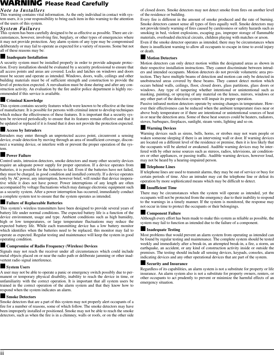
![Chapter 1: Quick Set Up4WLS912-433 Wireless Glassbreak DetectorThe wireless glassbreak detector can be used to provide wireless glassbreak detec-tion. The unit comes with three AA batteries.WLS914-433 Dual PIR Wireless Motion DetectorThe dual PIR wireless motion detector can be used to provide wireless space protec-tion. The unit comes with four AA batteries.WLS925L-433 Mini Wireless Universal TransmitterThe WLS925L-433 wireless universal transmitter is a smaller transmitter that can be used for door and window contacts. The unit comes with one Lithium battery and has built-in contacts.WLS929-433 Wireless KeyThe wireless key can be used to provide a simple and mobile method of arming and disarming the system. The unit comes with three Photo/Electronic 1.5V batteries.This system can have a maximum of 16 Wireless Keys.NT9201 Remote SounderYou can connect a hardwired remote sounder to the NT9010 system. This sounder provides an additional station for the NT9010 to sound alarms and system status, and for central station talk/listen-in sessions. NOTE: Maximum distance for the Remote Sounder is 500ft (152m) using 22AWG sheilded cable.1.1.5 Peel-off Instruction LabelsThe Envoy unit comes with a set of peel-off instruction labels already applied. Installer should remove these labels after installation. For future programming needs, please see sample labels below for instructions.The NT9010's "Flash" programming will help you to quickly set up the system.To begin:1. Press [ ][8]2. Enter the default installer’s code: [5555]3. Follow the audio instructionbuttons [A] to [F] for entering letters in serial numbers.✱For contacts used on the hardwired zones:Enter serial number 200001 for the first hardwired zoneEnter serial number 200002 for the second hardwired zone.Use!!1= YES2= NOSelection Type 2 (TX) Type 3 (PIR) Type 4 (Smoke)[A] Preset Front Door Main Floor Motion Main Floor Fire[B] Preset Back Door Upstairs Motion Upstairs Fire[C] Preset Garage Door Downstairs Motion Downstairs Fire[D] Preset Window Hallway Motion Hallway Fire[E] Preset Patio Door Garage Motion Garage FirePlease use buttons [A] to [E] for standard label optionsALSO REFER TO INSTALLATION MANUALPEELOFFABCDEFBackForwardPEELOFFA = StayB = AwayC = ChimeD = ExitE = StatusF = VolumeBack = RecordForward = Playback](https://usermanual.wiki/Tyco-Safety-Canada/01NB9010/User-Guide-129702-Page-8.png)
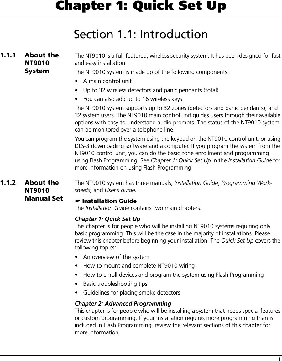
![Chapter 1: Quick Set Up8Use the following NT9010 terminals to make your zone connections:There are two different ways in which zones may be wired, depending on which programming options have been selected. The system can be programmed to supervise nor-mally closed, or Single End of Line loops. Please refer to the following sections to study each type of individually super-vised zone wiring. Normally Closed (NC) LoopsTo enable normally closed loops, programming section [013], option [1] must be ON.NOTE: This option should only be selected if Normally Closed (NC) devices/contacts are being used.Normally Closed Loops . . . . . . . . . . . . . . . . . . . . . . . . . . Section [013], Option [1]Single End Of Line (EOL) ResistorsTo enable system detection of single end of line resistors, programming section [013], option [1] must be OFF.NOTE: This option should be selected if either Normally Closed (NC) or Normally Open (NO) detection devices or contacts are being used.End of Line Resistors . . . . . . . . . . . . . . . . . . . . . . . . . . . . Section [013], Option [1]](https://usermanual.wiki/Tyco-Safety-Canada/01NB9010/User-Guide-129702-Page-12.png)
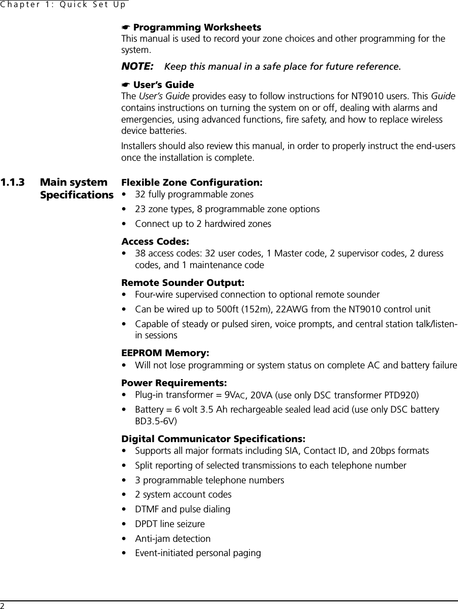
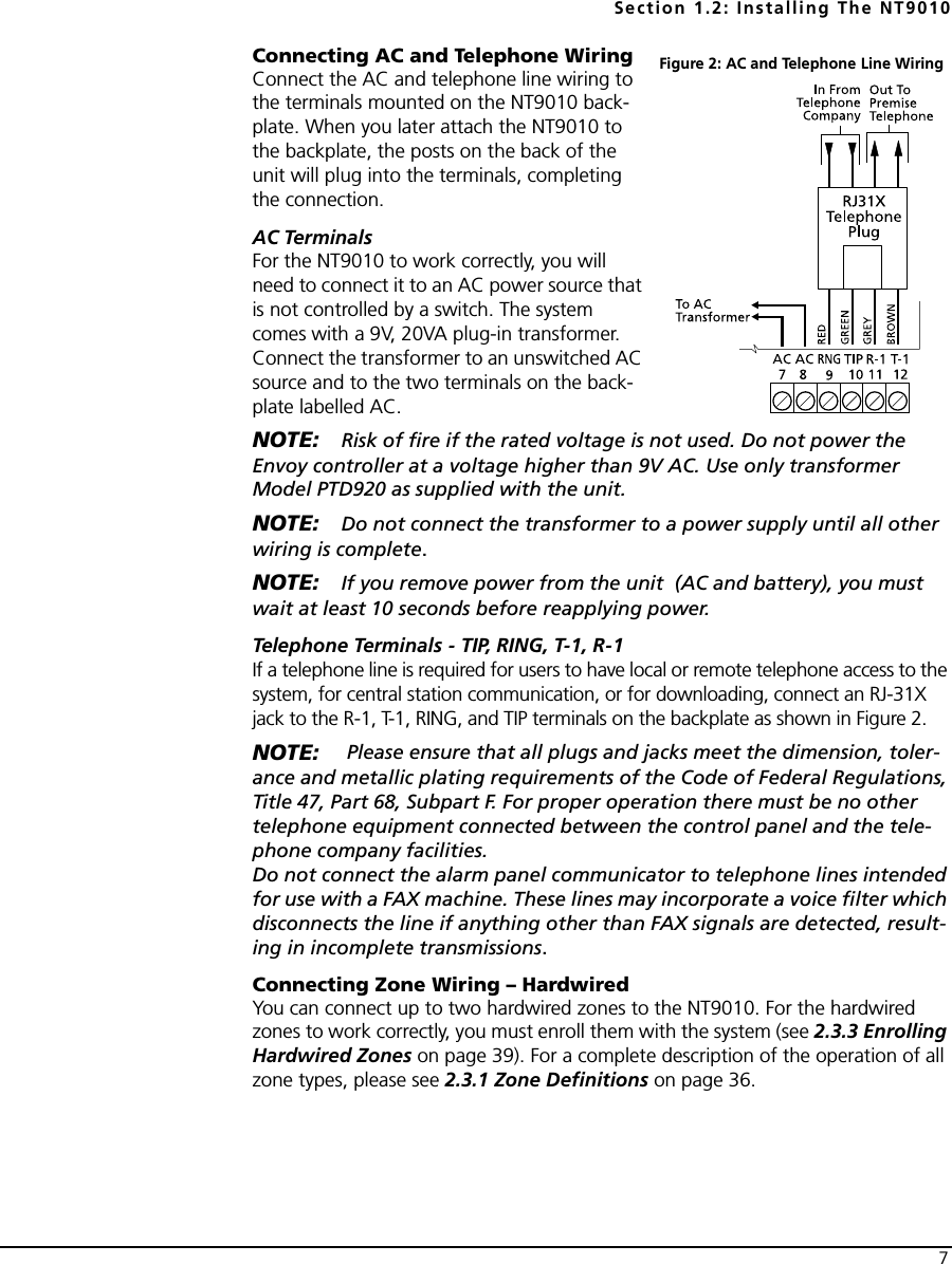
![Section 1.2: Installing The NT90109Keyswitch Zone WiringZones may be programmed to be used as keyswitch arming zones and must be wired according to the following diagram:For a complete description of how key-switch zones operate, see 2.3.1 Zone Definitions on page 36.Connecting the Remote SounderYou can connect a hardwired remote sounder to the NT9010 system. This sounder provides an additional station for the NT9010 to sound alarms and system status, and for central station talk/listen-in sessions.Connect the remote sounder to the NT9010 con-trol unit as shown below:For the sounder to work on the system you must also turn on the Remote Annunciation option. When this option is turned on, the remote sounder will also be supervised. The Local Annunciation option controls the sounder in the NT9010 control unit. If you turn this option off, there will be no alarms or voice prompts from the NT9010. If both options are on, there will be sound from both the NT9010 and the Remote Sounder.If there is a Remote Sounder on the system and it does not report a supervisory sig-nal within 30 seconds, a “Service Required” trouble will be generated, and a “Remote Sounder Trouble” event will be logged in the buffer.See also 2.3.13 Talk/Listen-in Programming on page 49.Local Annunciation . . . . . . . . . . . . . . . . . . . . . . . . . . . . . Section [017], Option [4]Remote Annunciation . . . . . . . . . . . . . . . . . . . . . . . . . . . Section [017], Option [5]Attach NT9010 to BackplateNOTE: Before attaching the backplate, be sure to connect the battery. See 1.2.5 Connecting the Battery on page 6.When you have mounted the backplate to the wall, completed the wiring, and connected the battery, you can attach the NT9010 unit to the backplate.1. Push the bottom of the NT9010 onto the back-plate posts, as shown at right.2. Snap the top of the NT9010 onto the top of the backplate, as shown at right.3. Secure the NT9010 to the backplate by replacing the plastic screw in the top of the NT9010.WALL1. Push bottomof NT9010 ontobackplate posts2. Snap top ofNT9010 ontotop of backplate](https://usermanual.wiki/Tyco-Safety-Canada/01NB9010/User-Guide-129702-Page-13.png)
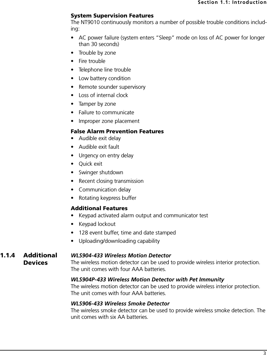
![Chapter 1: Quick Set Up101.2.6 Mounting the Wireless DevicesDo not permanently mount the wireless devices until you have completed the Placement Tests (see 1.2.7 Enrolling Devices and Setting Up the System on page 10). Once you have a good location for each of the devices, follow the mounting instructions on the Installation Instruction sheet for each device. For WLS904P-433, see Appendix D: WLS904P Wireless Motion Detector Installa-tion Instructions on page 62. For WLS925L-433, see Appendix C: WLS925L-433 Mini Door/Window Contact Installation Instructions on page 61.1.2.7 Enrolling Devices and Setting Up the SystemFlash Programming will guide you through the steps needed to set up each zone and basic system programming. If you need to perform more advanced programming for your installation, please see Chapter 2: Advanced Programming on page 15. To access Flash Programming:1. Press [✱][8].2. Enter the Installer’s code. The Installer Code is [5555] at default, but should be changed to prevent unauthorized access to programming.3. Press [1] to enter Flash Programming.4. Follow the audio instructions announced by Flash Programming. Flash Program-ming will guide you through the following programming areas:■Device enrollment■Zone label assignment■Central station telephone number■System account code■Placement tests of each wireless deviceYou can use the Forward (Playback) button to advance to the next section in Flash Programming, and the Backward (Record) button to return to the previous section.5. Be sure to record all the zone serial numbers and your programming choices in the NT9010 Programming Worksheets. Here are some notes about system programming done through Flash Programming.Zone DefinitionsWhen you enter a serial number for a device into the NT9010 Flash Programming, the unit will analyze the number to determine what kind of device you are enroll-ing. Based on the type of device, the system will make the following programming choices:Device Type Zone Definition Other ProgrammingDoor/window contact (2XXXXX, including hard-wired contacts entered as 200001 and 200002)Delay 1 (Type [01]) For hardwired zones (serial numbers 200001 and 200002), Zone Supervision disabled (section [804])Motion or glassbreak detector (3XXXXX)Interior Stay/Away (Type [05])NoneSmoke detector (4XXXXX)Delayed 24 Hour Fire (Type [87])NoneWireless key (6XXXXX) None None](https://usermanual.wiki/Tyco-Safety-Canada/01NB9010/User-Guide-129702-Page-14.png)
![Section 1.2: Installing The NT901011NOTE: To ensure that the NT9010 works properly, you should enroll all entry/exit point zones first.NOTE: PIR’s covering entry points should be zone type [06] Delay Stay/Away[01] Delay 1 Zone: If this zone is violated when the system is armed (e.g. door or window is opened), the entry delay will begin. The buzzer will sound to warn the user that the system must be disarmed. If the system is not disarmed before the entry delay expires, an alarm will be generated.[05] Interior Stay/Away Zone: If this type of zone is violated when the system is armed (e.g. the motion detector senses motion), an instant alarm will be generated unless a Delay Zone is violated first. If a Delay Zone is violated first, this zone will also follow the entry delay. The zone will be automatically bypassed under the following condi-tions:■the NT9010 is armed in the Stay Mode■the NT9010 is armed without entry delay ([✱][9] arming)■the NT9010 is armed with an access code and during the exit delay a Delay zone is NOT violated (user does not go through the entry/exit door).If zones are automatically bypassed, the user can reactivate the zones by entering [✱][1].[87] Delayed 24 Hour Fire (Wireless): If this zone is violated (e.g. the smoke detector senses smoke), the alarm will immediately sound, but the alarm communication to the central station will be delayed for 30 seconds. If during the 30 second delay the user presses the [#] key, the alarm and communicator will be delayed an additional 90 seconds. This provides time for a user to correct the problem. If after the 90 second delay the zone is still violated the process will begin again: the alarm will sound but the alarm communication will be delayed for 30 seconds.If the user does not press the [#] key, after 30 seconds the alarm will latch on and the system will communicate a fire alarm to the central station. The alarm will sound until the Bell Cutoff time expires, or until a valid code is entered.](https://usermanual.wiki/Tyco-Safety-Canada/01NB9010/User-Guide-129702-Page-15.png)
![Chapter 1: Quick Set Up12Programming Zone LabelsIf an enrolled device is a door/window contact, motion detector, glassbreak detec-tor, or smoke detector the system will then prompt you to enter an audio label for the new zone. You can choose from any of the following preset audio labels:If necessary, you can also program custom labels for the zones through the NT9010 Flash Programming. 1. For door/window contacts, motion detectors, and glassbreak detectors, at the appropriate place in Flash Programming, instead of selecting labels A to E, press function key F.2. You can now enter up to six pre-programmed words from the Audio Label Library. For each word you want to program, enter a 3-digit code from the Label Library (for a list of labels and codes, see the NT9010 Programming Worksheets, Appendix A). If your label is less than six words, press [#] at the end of the label.3. If you want to use a recorded label instead of the words available in the Audio Label Library, enter [244] for the first label entry, then the number of the label [001] to [005]. The recorded label will replace all six words in the section. You will not be able to add additional words to the label. To record a label for a zone, please see section 2.1.5 Programming Audio Labels on page 16.4. When you have entered the label, the system will recite it. If the label is correct, press [1]. If the label is not correct, press [2] and repeat steps 1 to 3 to fix the label.NOTE: You must accept a label to exit this section. If you choose F for a custom label, then you must create your own label using the Audio Label Library and accept it.NOTE: If you chose one of the audio labels, section [001] to [005] (#3 above) and there is no audio label recorded, the label will default to “zone X” where “X” is the zone number of the device enrolled. When the label is recorded in section [807], [701] to [705] it will be used.Entering the Central Station Telephone NumberWhen prompted, enter the telephone number for the central station. The number can be up to 32 digits long. When you program the number, the system automati-cally inserts the hexadecimal digit “D” at the beginning, to tell the system to con-Press Function Key:Door/window contacts (2XXXXX)Motion or glassbreak detector (3XXXXX)Smoke detector (4XXXXX)A Front door Main floor motion Main floor fireB Back door Upstairs motion Upstairs fireC Garage door Downstairs motion Downstairs fireD Window Hallway motion Hallway fireE Patio door Garage motion Garage fire](https://usermanual.wiki/Tyco-Safety-Canada/01NB9010/User-Guide-129702-Page-16.png)
![Section 1.2: Installing The NT901013duct a dial tone search before dialing. If necessary, you can enter the following hexadecimal digits in the telephone number:• HEX B to dial “✱” (function button B “Away”)• HEX C to dial “#” (function button C “Chime”)• HEX D for an additional dial tone search (function button D “Exit”)• HEX E to insert a 2-second pause (function button E “Status”)When you have finished entering the telephone number, press [✱]. The system will recite the number back to you.Entering the Account CodeThe system will send the account code to the central station when communicating system events (e.g. Low Battery, Test Transmission). Enter a 4-digit code.Testing the Placement of Wireless DevicesEach wireless detector must pass three consecutive placement tests before it will work properly on the system. Follow the instructions in Flash Programming to con-duct the tests. The buzzer will squawk once for “Good” placement and three times for “Bad” placement.If you exit the Placement Test section before all the zones have passed the neces-sary placement tests, a General System Trouble is generated. This trouble can only be cleared by re-entering the Placement Test and testing all of the devices that have not yet passed, or by deleting the serial numbers of the devices that did not pass the test (see 1.2.9 Deleting Wireless Devices on page 13).NOTE: Deleting or passing the zone through DLS will not clear this trouble.1.2.8 Other NT9010 OptionsAfter all zones have passed the Placement Test, Flash Programming will move to the advanced programming sections. If you do not need to do more programming, press [#] to exit.If you need to complete programming not covered by Flash Programming, please see Chapter 2: Advanced Programming on page 15 . For example, you may need to change the definitions of one or more zones. This programming is described in 2.3.1 Zone Definitions on page 36.1.2.9 Deleting Wireless DevicesTo remove a wireless device from the system, you will need to use the advanced programming sections. 1. Press [✱][8], then enter the Installer’s code. The default Installer’s code is [5555].3. When prompted, press [2] to go to advanced programming.4. Enter [804], then enter the 2-digit number of the zone you want to delete (01 - 32). The system announces the current serial number for the zone.5. Program the serial number for the zone as [000000]. The wireless device for the zone will be removed.NOTE: You may need to remove power from the system and then restore it to clear troubles caused by deleted zones.](https://usermanual.wiki/Tyco-Safety-Canada/01NB9010/User-Guide-129702-Page-17.png)
![15Chapter 2: Advanced ProgrammingSection 2.1: Programming the NT9010The chapter describes how to use advanced programming. For instructions on using Flash Programming, please see Chapter 1: Quick Set Up Guide.2.1.1 How to Enter Advanced ProgrammingYou can use the Advanced Programming to set all communicator and system options. The Installer Code is [5555] at default, but should be changed to prevent unauthorized access to programming.Step 1: From any keypad enter [✱][8][Installer Code].• The System light will flash and the Armed light will turn on to indicate you are in programming • The NT9010 will announce “To use Flash Programming press 1. To bypass Flash Programming press 2.”Step 2: To skip Flash Programming and go to the advanced programming sections, press [2].Step 3: Enter the 3-digit section number you want to program.• The Armed light will turn off and the Ready light will turn on to indicate the sys-tem is ready for the information for the selected section• You can use the Forward (Playback) button to go forward through the advanced programming data. The Backward (Record) button will not work in the advanced programming sections, except for sections [301] to [303], and [402].Step 4: Sections [802], [804], or [807] have 2- or 3-digit sub-sections. To access programming in these sections enter the programming sub-section number.NOTE: If the section number entered is not valid, the NT9010 will sound an error tone and say the section number that was entered.Installer Code . . . . . . . . . . . . . . . . . . . . . . . . . . . . . . . . . . . . . . . . . . Section [006]2.1.2 Programming Decimal DataWhen the Ready light is ON the NT9010 is waiting for the information to be pro-grammed for the selected section. If a digit is entered for each program box in a section the system will automatically exit from the section. It will turn OFF the Ready light and turn the Armed light back ON.You can also press the [#] key to exit a section before entering data for every box. This is handy if you only need to change the first few program boxes. All other loca-tions in the section will remain unchanged. If the [#] key is pressed the system will turn OFF the Ready light, turn ON the Armed light and exit from the section.](https://usermanual.wiki/Tyco-Safety-Canada/01NB9010/User-Guide-129702-Page-19.png)
![Chapter 2: Advanced Programming16You can use also the Forward (Playback) button to go forwards through the pro-gramming data. The Backward (Record) button will not work in the advanced pro-gramming sections (except for sections [301] to [303], and section [402]).2.1.3 Programming Hexadecimal DataYou may need to enter hexadecimal (HEX) digits for some of the programming sec-tions. To program a HEX digit press the function button corresponding to the HEX digit you want to program: Button Name HEX DigitStay AAway BChime CExit DStatus EVolume FIf you enter information into a section and make a mistake, press the [#] key to exit the section. Select that section again and re-enter the information correctly.If you are using a pulse communications format, a decimal zero [0] does not trans-mit. Programming a zero [0] tells the system not to send any pulses for that digit. To make a zero [0] transmit, it must be programmed as a Hexadecimal ‘A’.2.1.4 Programming Toggle OptionsSome sections contain several toggle options. Refer to the Programming Work-sheets to determine what each option represents. When you enter a toggle option section, the NT9010 recites the numbers of the options that are currently ON.Press the number corresponding to the option to toggle it ON or OFF. Once all the toggle options have been selected correctly press the [#] key to exit the section and save the changes.2.1.5 Programming Audio LabelsYou can program audio labels for the system, and for each of the zones. If you enroll the zones using Flash Programming, you can choose from five pre-set labels for the zone (please see Chapter 1: Quick Set Up). Alternatively, you can program custom labels using the advanced programming sections. To program or change a label:1. From Advanced Programming, enter section [807].2. Enter the 3-digit sub-section number of the label ([601] to [633]). The system announces the section number and then recites the words presently pro-grammed in the label. Each label may have up to six words. The system then prompts:“Enter three digit word. To exit, press pound”.3. Enter the 3-digit code for each word you want to program. You can enter up to six words for each label. Please see Appendix A: Audio Label Library on page 27 in Programming Worksheets for a list of the 3-digit codes for each available word. To add numbers to a label, see Adding Numbers to Labels on page 17. If your label is less than six words, press [#] at the end of the label.](https://usermanual.wiki/Tyco-Safety-Canada/01NB9010/User-Guide-129702-Page-20.png)
![Section 2.1: Programming the NT9010174. If you want to use a recorded label, in place of the first word of the label enter [244], then the number of the label [001] to [005]. The recorded label will replace all six words in the section. To record a label, see Recording Custom Labels on page 17.5. When you have entered the label, the system will recite it. If the label is correct, press [#]. To change the label, repeat steps 1-4, above.6. Record the new label in the appropriate section of the Programming Work-sheets.Adding Numbers to LabelsThree special Number Commands are available to allow the system to include a number in the voice label. The number commands allow the system to announce the number in three different modes:Label 000: Number Command 1, Combined Form. The number will be announced in its full form. For example, the number 401 would be announced as “four hundred and one”.Label 001: Number Command 2, Ordered Form. The number will be announced in a descriptive form. For example, the number 401 would be announced as “four hundred and first”.Label 002: Number Command 3, Individual Numbers. Each digit in the number will be announced individually. For example, the number 401 would be announced as “four zero one”.The number commands take up two of the six available word spaces in a label. In the first space select the type of announcement for the number (Number Com-mand 000, 001 or 002). In the second space program the 3-digit number to be read (from 000 to 999). NOTE: Because number commands take up 2 label spaces, you cannot program them in the sixth entry spot for a label.Recording Custom LabelsYou can record up to five custom labels for the system and for the zones using pro-gramming sections [701] to [705]. You can use any of these labels for the system or zone labels, instead of the words available in the Audio Label Library. To record a custom label:1. From Advanced Programming, enter [807].2. Enter one of sub-sections [701] to [705].3. Press the Record function key on the NT9010.4. Speak into the NT9010 microphone. Each label can be up to 1.5 seconds long. To stop recording, press [#].5. When you are finished recording, press the Playback function key. The NT9010 plays your recorded label back to you. To listen to the label again, press Playback again.6. If you want to re-record the label, press the Record function key again.7. To record more labels, repeat steps 1 to 5.](https://usermanual.wiki/Tyco-Safety-Canada/01NB9010/User-Guide-129702-Page-21.png)
![Chapter 2: Advanced Programming18NOTE: If the NT9010 is completely powered down (both AC and battery power are lost), the recorded labels will be lost.2.1.6 Reviewing ProgrammingTo review the current programming for a section enter the 3-digit section number. The NT9010 will announce the data programmed. If the programming is correct press [#] to exit the section, otherwise enter the correct data.2.1.7 Exiting ProgrammingWhen the NT9010 announces “Enter Section Number”, press the [#] key.](https://usermanual.wiki/Tyco-Safety-Canada/01NB9010/User-Guide-129702-Page-22.png)
![19Section 2.2: Changing How the NT9010Works For UsersMost NT9010 installations will only require basic programming. You can complete the basic programming using the NT9010 Flash Programming (please see Chapter 1: Quick Set Up for more information). The NT9010 User’s Guide provides basic directions for arming and disarming the system, bypassing zones and performing user func-tions. The following sections provide information on how to customize the NT9010 interface for your users, and how to change which options are available to NT9010 users.2.2.1 Accessing the NT9010 System Using a TelephoneAccessing the NT9010 Using a Local TelephoneTo access the NT9010 system using a premise telephone, pick up any local Touch-To n e 1 telephone and enter the three digit Telephone Access Code (default [✱✱✱]). The NT9010 will seize the line and announce “Hello.” If the Access Code Required for Local Access option is enabled (section [807]-[021] option [02]) the NT9010 will announce: “Enter your Access Code.” Enter your four or six-digit system access code. Invalid access codes count towards the Keypad Lockout, if enabled.You can access the NT9010 using a local telephone, even if the telephone line is disconnected. For this to operate properly, you must enable Telephone Line Mon-itoring on the system (see 2.3.15 Telephone Line Monitoring (TLM) on page 53).You can change the Telephone Access Code to any 3 digit code using numbers 0 through 9 as well as the [✱] and [#] keys. This access code can only be changed through Advanced Programming.NOTE: Avoid programming this code as a valid 3 digit area code or tele-phone service. Avoid numbers such as [911], [411], [611] or [0XX]. Do not try to exit this section by pressing [#], it will be accepted as a valid digit. To exit, program all 3 digits of the code or press [Forward].Telephone Access Code . . . . . . . . . . . . . . . . . . . . . . . . . . . . . . Section [807]-[020]Code Required for Local Access . . . . . . . . . . . . . . . .Section [807]-[021], Option [2]TLM Enable/Disable . . . . . . . . . . . . . . . . . . . . . . . . . . . . . Section [015], Option [7]Keypad Lockout. . . . . . . . . . . . . . . . . . . . . . . . . . . . . . . . . . . . . . . . . Section [012]Accessing the NT9010 Using a Remote TelephoneIf the Remote Access option (section [807]-[021], option [01]) is enabled users can access the system from any Touch-Tone* telephone in the world.NOTE: Please pause for 1 second between key presses when enter-ing access codes or commands on a remote phone.1. Touch-Tone is a trademark of Stentor Resource Centre Inc.](https://usermanual.wiki/Tyco-Safety-Canada/01NB9010/User-Guide-129702-Page-23.png)
![Chapter 2: Advanced Programming201. Call the telephone number the NT9010 system is connected to. 2. Let the telephone ring one or two times. 3. Hang up and wait 10 seconds before calling again. The NT9010 will answer after the first or second ring and announce “Hello.”4. Enter the 3-digit Telephone Access Code. If this is not entered within 10 sec-onds the NT9010 will hang up. Once the correct code has been entered, the system will prompt,“Enter your Access Code.”5. Enter a 4- or 6-digit access code. The NT9010 will begin to announce the status of the system. If you do not enter an access code within 20 seconds, or if you enter it incorrectly 3 times, the NT9010 will hang up. Invalid access codes count towards the Keypad Lockout, if enabled (see 2.2.13 Keypad Options on page 34).NOTE: The Maintenance Code can be used to access the system from a remote telephone.Remote Access Enabled/Disabled . . . . . . . . . . . . . . .Section [807]-[021], Option [1]2.2.2 Access Codes For instructions on programming access codes, see the NT9010 User’s Guide (Programming Access Codes).General access codes can arm and disarm the system. When the Code Required for Bypassing option is enabled, users will need to enter a valid access code in order to bypass zones. Individual access codes can have the Zone Bypassing attribute disabled under Access Code Attribute programming, see Programming Access Code Attributes on page 21.If the 6-Digit User Access Codes option is enabled, all the access codes may be programmed with six digits instead of four, with the exception of the Panel ID code and the Downloading Access Code. The Installer’s Code will become [555555]. If 4-digit codes are already programmed and this option is selected, the first four digits of the programmed codes will remain as programmed and the last two digits will be [00].If the 4-Digit User Access Codes is selected, all codes will be 4-Digits in length. If 6-digit codes were previously programmed and this option is enabled, the last two digits of each code will be erased.The available access codes are as follows:General Access Codes - Access Codes [01] to [32]Each access code can be used to arm and disarm the system. Additional access code attributes are also programmable to determine what abilities the code will have.You can program access code attributes by following the instructions in this sec-tion.](https://usermanual.wiki/Tyco-Safety-Canada/01NB9010/User-Guide-129702-Page-24.png)
![Section 2.2: Changing How the NT9010 Works For Users21Duress Codes - Access Codes [33] and [34]When a Duress Code is used to perform any function the system will send a Duress Reporting Code to the central station (see 2.3.12 CommunicatorReporting Codes on page 47).Master Code - Access Code [40]The Master Codes can perform any keypad function. These codes can be used to program all access codes, including the Duress Codes.If the Master Code Not Changeable option is enabled users will not be able to change the Master Code [40]. You will only be able to change it using Advanced Programming.Supervisor Codes - Access Codes [41] to [42]Supervisor Codes can program additional access codes. By default, Supervisor codes have the same attribute programming as the Master code. You can change the attribute programming for these codes by following the instructions in this section.Maintenance CodeThe maintenance code can only be used to arm and disarm the system. The main-tenance code will also allow remote (telephone) access to the system. It cannot be used to bypass zones, or for any other function. This code can only be programmed in Advanced Programming.Installer’s CodeYou will use the Installer’s Code to set up and to program the system. The Installer Code is [5555] at default, but should be changed to prevent unauthorized access to programming.Telephone Access CodeIf the NT9010 system is connected to the premise telephone line, users will be able to access their system using a premise or phone (see 2.2.1 Accessing the NT9010 System Using a Telephone on page 19). Users will need to enter a Telephone Access Code before they can use the NT9010 system. The default Telephone Access Code is [✱✱✱]. You can change this to any 3 digit code using numbers 0 through 9 as well as the [✱] and [#] keys. This access code can only be changed through Advanced Programming.NOTE: Avoid programming this code as a valid 3 digit area code or tele-phone service. Avoid numbers such as [911], [411], [611] or [0XX]. Do not try to exit this section by pressing [#], it will be accepted as a valid digit. To exit, program all 3 digits of the code or press [Forward].Programming Access Code AttributesAttributes determine what abilities an access code will have.By default, each code has the attributes of the code used to program it. For exam-ple, if you use the Master code to program other access codes, the new codes will have the same attributes as the Master code. You can change the attribute pro-gramming by following the instructions below.You cannot change Master code attribute programming. The Master code has all attributes turned on, except for the Bell Squawk on Arming/Disarming attribute.](https://usermanual.wiki/Tyco-Safety-Canada/01NB9010/User-Guide-129702-Page-25.png)
![Chapter 2: Advanced Programming22To program each attribute:1. Enter [✱][5][Master code][9] to enter the attribute programming mode. 2. Enter the 2-digit number of the access code you want to edit. 3. Enter the attribute number to toggle it on or off.The programmable attributes are as follows:• Attribute 1: User enabled for arming, disarming, alarm reset, auto-arm cancel (on by default)• Attribute 2: For future use• Attribute 3: Zone Bypass enabledThis attribute allows the user to bypass zones.• Attribute 4: NT9010 Telephone AccessThis attribute allows the user to access the security system from a telephone when an access code is required.• Attributes 5-6: For future use• Attribute 7: Bell Squawk on Arming/Disarming. When this attribute is turned on, the bell will squawk when the access code is entered to arm or disarm the system. For example, you can use the arm/disarm bell squawk attribute to have wireless key access codes squawk the bell, while other codes are silent. To do this, enable attribute [7] on all access codes associated with wireless keys.NOTE: If you enable the Bell Squawk on Arming/Disarming option (sec-tion [014], option [1]), the bell will sound arm/disarm bell squawks for all access codes, regardless of the programming for attribute [7] (see 2.2.5 Arming and Disarming Options on page 24).Installer’s Code . . . . . . . . . . . . . . . . . . . . . . . . . . . . . . . . . . . . . . . . . Section [006]Master code . . . . . . . . . . . . . . . . . . . . . . . . . . . . . . . . . . . . . . . . . . . Section [007]Maintenance Code . . . . . . . . . . . . . . . . . . . . . . . . . . . . . . . . . . . . . . Section [008]Master Code Not Changeable . . . . . . . . . . . . . . . . . . . . . Section [015], Option [6]Code Required for Bypassing . . . . . . . . . . . . . . . . . . . . . Section [015], Option [5]6-digit User Access Codes . . . . . . . . . . . . . . . . . . . . . . . . Section [701], Option [5]Telephone Access Code . . . . . . . . . . . . . . . . . . . . . . . . . . . . . . .Section [807]-[020]2.2.3 Voice Prompt InterfaceYou can customize the voice prompt interface for the NT9010 users by turning indi-vidual prompts on or off, and by changing how the NT9010 system announces the current time.To have the NT9010 system announce the time in am/pm format (e.g. 9:00am), turn on the Clock is AM/PM option. To have the system announce the time in 24-hr format (e.g. 21:00), turn on the Clock is 24 Hour option.The NT9010 system is designed to be easy to use by reminding users of available commands. For example, after a user accesses the system, they can press [✱] and the NT9010 system will announce the [✱] commands that are available. You can avoid confusing users by turning on only the prompts that apply to the sys-tem you are installing. The options in sub-section [004] only affect the NT9010 sys-](https://usermanual.wiki/Tyco-Safety-Canada/01NB9010/User-Guide-129702-Page-26.png)
![Section 2.2: Changing How the NT9010 Works For Users23tem [✱] command prompts: if a prompt is disabled, users will still be able to enter the command it refers to.Sub-section [003] determines which Status prompts the user will hear. If an option is “ON”, the system will announce the prompt when the appropriate condition is present. If an option is “OFF”, the system will not announce the prompt if the con-dition is present. For example, if you turn off the “Zone Tamper” prompt, when a zone is tampered on the system, the NT9010 system will not announce it to the user.You can also have the NT9010 system announce the names of zones that are opened or closed by turning on the Verbal Chime option. When this option is turned on, if the Verbal Chime for Zone Openings is also enabled, whenever a zone with the Chime attribute enabled is opened, a series of beeps will sound and the NT9010 will prompt (for example):“Front Door”If the Verbal Chime for Zone Closings is enabled, the NT9010 system will announce the zone label when the zone is closed. See also [*] [4] Door Chime On/Off on page 29.You can create custom labels for the system and for each zone in the Labels pro-gramming area. Please see 2.1.5 Programming Audio Labels on page 16 for more information.Clock is AM/PM . . . . . . . . . . . . . . . . . . . . . . . . . . . .Section [807]-[002], Option [1]System Status Prompts. . . . . . . . . . . . . . . . . . . . . . . . . . . . . . . Section [807]-[003][✱] Command Prompts . . . . . . . . . . . . . . . . . . . . . . . . . . . . . . Section [807]-[004]Door Chime Zone Attribute . . . . . . . . . . . . . . . . Sections [101] to [132], Option [3]Verbal Chime Enabled/Disabled . . . . . . . . . . . . . . . . . . . . Section [017], Option [2]Verbal Chime for Zone Openings . . . . . . . . . . . . . . .Section [807]-[002], Option [2]Verbal Chime for Zone Closings . . . . . . . . . . . . . . . .Section [807]-[002], Option [3]Custom Zone Labels . . . . . . . . . . . . . . . . . . . . .Sections [807]-[601] to [807]-[632]2.2.4 Alarm Announce-mentsIf the Verbal Alarm option is turned on, the system will announce the first and last zones that have gone into alarm, along with the alarm tone. When a zone with the Audible attribute turned on goes into alarm, the NT9010 system will sound an alarm tone, but every 15 seconds it will pause the siren and the speaker will announce the zone(s) in alarm, for example:“Alarm South Bedroom Window”You can change the number of seconds between alarm announcements in the Alarm Tone Period for Verbal Alarm section.Zones programmed as Silent, and 24 Hour Supervisory Buzzer zones will not be announced or cause the unit to annunciate at full volume. NOTE: Fire annunciation always overrides any burglary zone alarm annunciation. Alarms from Fire or Panic keys override all other alarm announcements.](https://usermanual.wiki/Tyco-Safety-Canada/01NB9010/User-Guide-129702-Page-27.png)
![Chapter 2: Advanced Programming24NOTE: The alarm announcements will stop with the siren at the end of the Bell Time Out period.Verbal Alarm . . . . . . . . . . . . . . . . . . . . . . . . . . . . . . . . . . Section [017], Option [3]Alarm Tone Period for Verbal Alarm . . . . . . . . . . . . . . . . . . . . . .Section [807]-[030]2.2.5 Arming and Disarming OptionsIf the Arm/Disarm Bell Squawk option is enabled the system will squawk the alarm output once upon arming and twice upon disarming. If an alarm is in mem-ory, when the system is disarmed the bell will sound three pairs of disarm squawks. NOTE: If you enable the Bell Squawk on Arming/Disarming (section [014], option [1]), the bell will sound arm/disarm bell squawks for all access codes, regardless of the programming for attribute [7] (see 2.2.2 Access Codes on page 20).Enable both the Squawk on Away Arming/Disarming Only and the Arm/Dis-arm Bell Squawk options to have the system squawk the bell only when the sys-tem is away armed or disarmed.If the Opening After Alarm Keypad Ringback option is turned on, the system will beep the keypad 10 times rapidly if the system is disarmed after an alarm occurred. If the Opening After Alarm Bell Squawk option is turned on, the sys-tem will squawk the bell output 10 times rapidly if the system is disarmed after an alarm occurred.If the system is armed using the Stay function key, or by entering [✱][9][access code], there will be no bell squawks during entry and exit delays, except for the arm/disarm bell squawks.Closing Confirmation, if enabled, will cause the keypad to beep 10 times rapidly after the closing reporting code has been successfully transmitted to central station.If the AC/DC Inhibit Arming option is enabled, the system will not arm if there is an AC or DC (battery) trouble present on the system. Arming will not be allowed until the AC or battery trouble is cleared. If no AC or battery trouble is currently present, when a user attempts to arm the system, the system will do an automatic battery test. If the battery is good, the system will arm. If the battery is bad, the sys-tem will not arm.If the AC/DC Inhibit Arming option is disabled, the system will not do an automatic battery test when arming is attempted and the user will not be prevented from arming the system when there is an AC or battery trouble.If you enable the WLS Key Does Not Use Access Codes option, the disarm but-ton will work on wireless keys which have not been assigned access codes.To prevent disarming by wireless keys which don’t have access codes, disable this option. (See also 2.2.11 Programming Wireless Keys on page 33.)Arm/Disarm Bell Squawk . . . . . . . . . . . . . . . . . . . . . . . . . Section [014], Option [1]WLS Key Does Not Use Access Codes . . . . . . . . . . . . . . . Section [017], Option [1]Bell Squawk on Away Arming . . . . . . . . . . . . . . . . . . . . . Section [017], Option [8]Opening After Alarm Keypad Ringback . . . . . . . . . . . . . . Section [381], Option [1]](https://usermanual.wiki/Tyco-Safety-Canada/01NB9010/User-Guide-129702-Page-28.png)
![Section 2.2: Changing How the NT9010 Works For Users25Opening After Alarm Bell Ringback . . . . . . . . . . . . . . . . . Section [381], Option [2]Closing Confirmation. . . . . . . . . . . . . . . . . . . . . . . . . . . . Section [381], Option [4]AC/DC Inhibit Arming . . . . . . . . . . . . . . . . . . . . . . . . . . . Section [701], Option [3]2.2.6 Automatic ArmingYou can program the system to automatically arm at a specific time every day. Three items must be enabled in order to activate the auto arming function:1. The correct time of day must be programmed. For instructions on programming the time and date, see the NT9010 User’s Guide (“Setting the Time and Date”).2. Enter [✱][6][Master Code][2] to enable (three keypad beeps) or disable (one long beep) the auto-arm feature.3. Program the auto-arm time using the [✱][6][Master Code][3] command.When the internal system clock matches the programmed auto arm time, the sys-tem will check its status. If the system is armed, the NT9010 will do nothing until the programmed auto-arm time for the next day, when it will check again.If the system is disarmed at the auto-arm time, the NT9010 control unit will sound the keypad buzzer for one minute. This is the auto arm pre-alert period.If the Bell Squawk During Auto Arm option is enabled, the bell will squawk while the system is auto-arming in order to notify anyone on the premises that the system is being armed.If a valid access code is entered during the auto arm pre-alert period, automatic arming will be cancelled. If automatic arming is cancelled by a user, the system will send the Auto Arm Reporting Code to the central station.NOTE: The Maintenance code cannot be used to cancel automatic arming.If no code is entered during the auto-arm prealert, the system will auto-arm. If a zone is violated when the system arms, the system will transmit a Partial Closing Reporting Code (if programmed), to indicate the system was not secure. If the zone is restored, the NT9010 will arm the zone and add it back into the system.Program Time and Date. . . . . . . . . . . . . . . . . . . . . . . . . . . . [✱][6][Master Code][1]Enable Auto Arming . . . . . . . . . . . . . . . . . . . . . . . . . . . . . . [✱][6][Master Code][2]Program Auto Arm Time . . . . . . . . . . . . . . . . . . . . . . . . . . . [✱][6][Master Code][3]Partial Closing Reporting Code . . . . . . . . . . . . . . . . . . . . . . . . . . . . . Section [343]Auto Arm Cancellation Reporting Code . . . . . . . . . . . . . . . . . . . . . . . Section [348]Bell Squawk During Auto Arm . . . . . . . . . . . . . . . . . . . . . Section [014], Option [2]2.2.7 Entry and Exit Delay OptionsUpon arming, the system will begin the exit delay. If Audible Exit Delay is enabled the keypad will beep every second until the exit delay expires. The keypad will beep rapidly for the last 10 seconds of exit delay to warn the user the system is about to arm.Users can restart the exit delay one time while it is counting down by pressing the Away key. The system will not log the user who re-started the exit delay, unless the Quick Arming Disabled/Function Keys Require Code option is turned on (sec-tion [015], option [4]).](https://usermanual.wiki/Tyco-Safety-Canada/01NB9010/User-Guide-129702-Page-29.png)
![Chapter 2: Advanced Programming26NOTE: If the system has been Stay armed, or armed with no entry delay ([✱][9]), pressing the Away key will not start an exit delay.For some applications Bell Squawk on Exit Delay may be enabled. The system will squawk the alarm output once every second when the exit delay is initiated and 3 times a second for the last 10 seconds until the exit delay expires.Upon entry, if a Delay type zone is violated, the system will begin entry delay. The keypad will emit a steady tone. The keypad will pulse the keypad sounder during the last 10 seconds to warn the user the system is about to go into alarm. If there was an alarm during the armed period, the keypad sounder will pulse for the entire entry delay to warn the user of the previous alarm.For some applications Bell Squawk on Entry Delay may be enabled. The system will squawk the alarm output once every second until the entry delay expires or the system is disarmed.NOTE: Since two Delay zones are programmable, and therefore two dif-ferent Entry Delays, when the system is armed it will use the Entry Delay for the first Delay zone violated.If Exit Delay Termination is enabled the system will monitor the Delay zones dur-ing exit delay. If a Delay type zone is violated then secured during the exit delay, the exit delay will be terminated and the system will be armed immediately.To prevent false alarms, use the built-in feature Audible Exit Fault. If a delay type zone is violated within 10 seconds after the exit delay has expired, the system will sound the entry delay warning through the keypad and siren alerting the customer that an improper exit was made. If the system is disarmed within the entry delay no signal is sent. If not, the system will continue to sound the alarm and send a signal to central station. This feature can be disabled in Section [013] Option [6].Bell Squawk During Auto Arm . . . . . . . . . . . . . . . . . . . . . Section [014], Option [2]Bell Squawk on Exit Delay . . . . . . . . . . . . . . . . . . . . . . . . Section [014], Option [3]Bell Squawk on Entry Delay . . . . . . . . . . . . . . . . . . . . . . . Section [014], Option [4]Audible Exit Delay . . . . . . . . . . . . . . . . . . . . . . . . . . . . . . Section [014], Option [6]Audible Exit Fault. . . . . . . . . . . . . . . . . . . . . . . . . . . . . . . Section [013], Option [6]Exit Delay Termination . . . . . . . . . . . . . . . . . . . . . . . . . . . Section [014], Option [7]2.2.8 Bell Options When the system goes into alarm, the siren will sound. The siren will silence after the number of minutes programmed for the Bell Cut-off time have passed. The system supervises the remote sounder. If an open condition is detected, the system will immediately indicate a trouble condition by beeping the keypad twice every 10 seconds to alert users to the problem.If the Temporal Three Fire Signal option is enabled, all Fire signals will follow the Temporal Three Pattern as described in NFPA 72. If turned OFF all Fire signals will sound a one second on, one second off cadence.If Fire Bell Continuous is enabled, the alarm output will sound until a code is entered. If disabled, the alarm will sound until a code is entered or the bell cut-off time has expired.](https://usermanual.wiki/Tyco-Safety-Canada/01NB9010/User-Guide-129702-Page-30.png)
![Section 2.2: Changing How the NT9010 Works For Users27NOTE: Only fire zones will follow the Temporal Three Fire Signal.Bell Cut-off . . . . . . . . . . . . . . . . . . . . . . . . . . . . . . . . . . . . . . . . . . . . Section [005]Temporal Three Fire Signal Enable/Disable . . . . . . . . . . . . Section [013], Option [8]Fire Bell Continuous. . . . . . . . . . . . . . . . . . . . . . . . . . . . . Section [014], Option [8]2.2.9 User Commands[*] [1] Zone BypassingUsers can bypass individual zones using the [✱][1] keypad command. This command can be used if users want to have access to an area while the system is armed, or to bypass a defective zone (bad contact, damaged wiring) until service can be provided. A bypassed zone will not cause an alarm. Instructions on zone bypassing can be found in the NT9010 User’s Guide (“Zone Bypassing”). When the system is disarmed, all zones bypassed using [✱][1] will be unbypassed, except for 24-Hr zones.If the Code Required for Bypass option is enabled, an access code will be required to enter the Bypass mode. Only access codes with the Bypass attribute enabled will be able to bypass zones (see 2.2.2 Access Codes on page 20).If the Bypass Status Displayed While Armed option is chosen, the System light will be ON while the system is armed to indicate that there are bypassed zones.NOTE: If a 24 hour zone is bypassed, ensure that the zone is restored or disabled before removing the bypass.Code required for bypass . . . . . . . . . . . . . . . . . . . . . . . . . Section [015], Option [5]Bypass Displayed While Armed . . . . . . . . . . . . . . . . . . . . Section [016], Option [7][*] [2] Trouble AnnouncementsThe system constantly monitors itself for several different trouble conditions. If a trouble condition is present, the System light will be ON and the keypad will beep twice every 10 seconds. The trouble beep can be silenced by pressing any key on the keypad. If Bell Squawk on Trouble is enabled (section [014], option[5]), the bell will squawk every 10 seconds when a trouble condition is present.To listen to an announcement of trouble conditions:1. Press [✱] [2]. 2. The system will announce each trouble condition. Possible trouble conditions are described below:Service Required: The system has one or more of the following problems:• Low Battery: Main system backup battery charge is low. Trouble is restored when the battery is fully charged.• Remote Sounder Supervisory Trouble: The remote sounder is disconnected.• Bad Module Placement: One or more devices have not passed the Placement Te s t .• System Fault: Internal error on the system, return for repair.](https://usermanual.wiki/Tyco-Safety-Canada/01NB9010/User-Guide-129702-Page-31.png)
![Chapter 2: Advanced Programming28The NT9010 will only announce “Service Required”. If the control unit announces this trouble, users can press [1] to expand the troubles. The user should call for assistance. The specific trouble will be logged in the event buffer.AC Failure: AC power is no longer being supplied to the NT9010 control unit. To conserve power, when there is an AC Failure all lights will turn off, except for the flashing System light.Telephone Line Monitoring Trouble (TLM): There is a problem with the tele-phone line (See 2.3.15 Telephone Line Monitoring (TLM) on page 53.) Failure to Communicate (FTC): The communicator failed to communicate with any of the programmed telephone numbers (see 2.3.8 Communicator Dialing on page 41). Zone Fault (including Fire Zone): A zone on the system is experiencing trouble. This means that a zone could not generate an alarm on the system if required to do so (e.g. a fire zone is open, or a supervisory fault on a wireless zone). When a zone fault occurs, the unit will start to beep. Press [5] while in Trouble mode to hear an announcement of the affected zones.NOTE: A Fire zone trouble will be generated and announced in the armed state. Zone Tamper: The tamper switch is open on a wireless device. When a tamper condition occurs, the NT9010 will start to beep (if the system is armed, an alarm will occur). Press [6] while in the Trouble mode to hear an announcement of the affected zones. If a zone is tampered or faulted, it must be fully restored to clear the trouble. If a smoke detector is tampered, the Ready light will remain on and the system can be armed.NOTE: Once a zone is tampered or faulted, it must be completely restored before the trouble condition will clear.Device Low Battery: A wireless device has a low battery condition. Press [7] one, two, or three times to hear which devices are experiencing battery failure. The fol-lowing will occur:Keypad beeps: NT9010 Announces:Press [7] 1 Zones with low batteries Press [7] twice 3 Wireless keys with low batteries Loss of System Time: When the system is powered up, the internal clock needs to be set to the correct time. This trouble is cleared when an attempt is made to reset the clock.[*] [3] Alarm MemoryIf there is an alarm in memory when the system is disarmed, the System light will be on. Press [✱][3] to enter the alarm memory mode. The NT9010 system will announce the alarms that are in memory by zone number or label. For example:“There is 1 alarm in memory. Fire Zone. To exit, Press ‘#'.”Press [#] to return to the “Ready” mode. Alarm Memory is cleared when the system is armed.](https://usermanual.wiki/Tyco-Safety-Canada/01NB9010/User-Guide-129702-Page-32.png)
![Section 2.2: Changing How the NT9010 Works For Users29[*] [4] Door Chime On/OffUsers can turn the Door Chime feature on or off by pressing [✱][4]. If the door chime feature is enabled the keypad will beep 6 times rapidly when a zone is opened and closed. The system will only do this for zones with the Door Chime Attribute enabled and if the door chime feature is enabled (see 2.3.2 Zone Attributes on page 38). You can have the NT9010 system announce the names of zones when they are opened or closed by turning on the Verbal Chime feature. Please see 2.2.3 Voice Prompt Interface on page 22.Door Chime Zone Attribute . . . . . . . . . . . . . . . . Sections [101] to [132], Option [3]Verbal Chime Enabled/Disabled . . . . . . . . . . . . . . . . . . . . Section [017], Option [2]Verbal Chime for Zone Openings . . . . . . . . . . . . . . .Section [807]-[002], Option [2]Verbal Chime for Zone Closings . . . . . . . . . . . . . . . .Section [807]-[002], Option [3][*] [5] Programming Access CodesAll access codes can be programmed using the [✱][5] command. For complete instructions on programming access codes, see the NT9010 User’s Guide (“Pro-gramming Access Codes”). For information on access code attribute programming, see 2.2.2 Access Codes on page 20.[*] [6] User FunctionsTo program user functions, perform the following:1. Press [✱] [6] [Master code]. The keypad will flash the ‘System’ light. 2. Press the number [1] to [7] for the item to be programmed.•[1] - Time and DateSee the NT9010 User’s Guide for instructions on setting the time and date (“Setting the Time and Date”).•[2] - Auto-Arm Enable/DisableEnter [2] to enable (three keypad beeps) or disable (one long beep) the auto-arm feature.•[3] - Auto-Arm ScheduleEnter [3] to change the auto-arm time. Enter the auto-arm time in 24-hour format (i.e. enter a 4-digit number in [hhmm] format).•[4] - System TestFor step-by-step instructions on performing a system test, see the NT9010 User’s Guide (“Full System Test”). When [4] is pressed the system will perform the following:■sound the alarm output for two seconds ■light all lights on the keypad■sound the keypad buzzer for two seconds ■test the NT9010 battery■send a System Test Reporting code, if programmed (see 2.3.12 CommunicatorReporting Codes on page 47).•[5] - Enable DLS (Downloading)When [5] is pressed the system will turn on the downloading option for 1 or 6](https://usermanual.wiki/Tyco-Safety-Canada/01NB9010/User-Guide-129702-Page-33.png)
![Chapter 2: Advanced Programming30hours. During this time the system will answer incoming downloading calls (see 2.3.14 Downloading on page 51). • [6] – User-Initiated Call-UpWhen [6] is pressed, the system will initiate a call to the downloading computer.•[7] Telephone Volume ControlYou can change the volume of the voice prompts heard when you access the NT9010 system by telephone. When you press [7], the NT9010 will prompt “Phone Volume is High. To change phone volume, press ‘1’. To exit press #.” Options are ‘Low’, ‘Medium’, and ‘High’, with ‘High’ as the default. You can change the current selection by pressing [1].NOTE: To change the volume of the voice prompts from the NT9010 unit you must use the Volume Key on the NT9010.[*] [8] Flash Programming / Advanced ProgrammingEnter [✱][8] followed by the Installer Code to enter Flash Programming, or the Advanced Programming sections (see Section 2.1: Programming the NT9010 on page 15).[*] [9] Arming Without Entry DelayWhen a system is armed with the [✱][9] command the system will remove the entry delay from the system. After the exit delay, Delay 1 and Delay 2 type zones will be instant and Stay/Away zones will remain bypassed. (see 2.3.1 Zone Definitions on page 36). When the system is armed in this mode, the Armed light will be flashing and NT9010 will announce that there are zones bypassed.For more information regarding this feature, see the NT9010 User’s Guide.[*] [0] Quick ArmIf the Quick Arm Enable option is on, the system can be armed by entering [✱][0]. This is a useful method of arming the system when someone doesn’t have an access code.NOTE: The Quick Arm feature must be enabled in order for the Stay/Away function keys to operate as intended. If the feature is not enabled, the user will be required to enter a valid access code after pressing the Stay or Away function key in order to arm the system in the stay or away mode.[*] [0] Quick ExitQuick Exit will allow someone to leave an armed premise through a Delay type zone without having to disarm and rearm the system.When [✱][0] is entered, if the Quick Exit Enabled option is on, the system will pro-vide a two minute window to exit. During this time the system will ignore the first activation of a Delay type zone. When the Delay zone is secured the system will end the two minute time period.If a second Delay zone is tripped, or if the zone is not restored after two minutes, the system will start entry delay.Quick Arm Enable . . . . . . . . . . . . . . . . . . . . . . . . . . . . . . Section [015], Option [4] Quick Exit Enable. . . . . . . . . . . . . . . . . . . . . . . . . . . . . . . Section [015], Option [3]](https://usermanual.wiki/Tyco-Safety-Canada/01NB9010/User-Guide-129702-Page-34.png)
![Section 2.2: Changing How the NT9010 Works For Users312.2.10 Function KeysThere are eight function keys on the NT9010 labelled Stay, Away, Chime, Exit, Sta-tus, Volume, Record and Playback. The operation of these keys is described below. Users can activate each function by pressing the key.The programming of any function key on the NT9010 may be changed to any of the options listed below. To change the programming of a function key:1. Enter [✱][8][Installer’s Code].2. Enter section [807].3. Enter [000] for function key programming.4. Enter the 2-digit code for the function you want to program for each key. (Each function is described below.)5. When you are finished, press [#] to exit.[00] - Null KeyThe key is not used and will perform no function when pressed.[01] - [02] For future use[03] - Stay ArmArms the system in Stay mode. All Stay/Away type zones will be automatically bypassed. Delay type zones will provide entry and exit delay. The Quick Arm fea-ture must be enabled for this key to function (Section [015], Option [4]). If Quick Arming is not enabled, the user must enter a valid access code after pressing the function key in order to arm the system in the Stay mode.[04] - Away ArmArms the system in Away mode. All Stay/Away type zones will be active at the end of the exit delay. Delay type zones will provide entry and exit delay. The Quick Arm feature must be enabled for this key to function (Section [015], option [4]). If Quick Arming is not enabled, the user must enter a valid access code after pressing the function key in order to arm the system in the Away mode.[05] - [✱]+[9] No-Entry Delay ArmAfter this function key is pressed the user must enter a valid access code. The sys-tem will arm and remove entry delay from the system when the exit delay expires (see [*] [9] Arming Without Entry Delay on page 30).[06] - [✱]+[4] Door Chime On/OffPressing the key will toggle the Door Chime feature ON or OFF. One solid beep means the feature has been disabled, three short beeps means it has been enabled.[07] - [✱]+[6]...[4] System TestThis function key provides the user with a simple method for testing the system (see [*] [6] User Functions on page 29).[08] - [✱]+[1] Bypass ModeThis function key provides the user with a simple method for entering the Bypass Mode. If an access code is required it must be entered before bypassing can be per-formed (see [*] [1] Zone Bypassing on page 27).](https://usermanual.wiki/Tyco-Safety-Canada/01NB9010/User-Guide-129702-Page-35.png)
![Chapter 2: Advanced Programming32[09] - [✱]+[2] Trouble DisplayThis function key provides the user with a simple method for entering the Trouble Display Mode (see [*] [2] Trouble Announcements on page 27).[10] - [✱]+[3] Alarm MemoryThis function key provides the user with a simple method for entering the Alarm Memory Display Mode (see [*] [3] Alarm Memory on page 28).[11] - [✱]+[5] Programming Access CodesThis function key provides the user with a simple method for programming access codes. After this key is pressed a valid System Master or Supervisor Code will have to be entered before the system will allow programming to be performed (see [*] [5] Programming Access Codes on page 29).[12] - [✱]+[6] User FunctionsThis function key provides the user with a simple method for programming User Functions. After this key is pressed a valid System Master or Supervisor code must be entered before the system will allow User Functions to be performed (see [*] [5] Programming Access Codes on page 29).[13] - [15] For future use[16] - [✱]+[0] Quick ExitPressing this key will cause the system to activate the Quick Exit feature (see section [*] [0] Quick Exit on page 30).[17] - [✱]+[1] Reactivate Stay/Away ZonesThis function key provides the user with a simple method for adding Stay/Away zones back into the system (see [*] [1] Zone Bypassing on page 27).[18] - [26] For future use[27] - StatusPress this key to have the NT9010 announce the time and the current status of the system. For example, the system may announce:“Zones are open. Zone 1. Secure system before turning on. For more options, press [✱].”Pressing this key while the unit is speaking will cause the unit to stop speaking.[28] - VolumeTo change the volume of NT9010 announcements, press this key. The NT9010 will announce the different volume levels. [29] - RecordPress this key to begin recording a message through the NT9010 microphone. After you hear the prompt “Record Memo Now” and a single 1 second tone, begin recording your message. When you are finished recording, press [#].[30] - PlaybackPress this key to listen to a recorded message. If there is no message recorded, the NT9010 will sound an error tone. You can stop playback of the recorded memo any time by pressing [#].](https://usermanual.wiki/Tyco-Safety-Canada/01NB9010/User-Guide-129702-Page-36.png)
![Section 2.2: Changing How the NT9010 Works For Users33NOTE: Keys [27] to [30] are instant function keys. They do not have to be held for 2 seconds to activate.2.2.11 Programming Wireless KeysIf you will be adding WLS929-433 wireless keys, after you enroll them on the sys-tem you may want to change the functions of the buttons on these devices.If you enable the WLS Key Does Not Use Access Codes option, the disarm but-ton will work on wireless keys which have not been assigned access codes. To pre-vent disarming by wireless keys which don’t have access codes, disable this option.To change wireless key function buttons, from Advanced Programming:1. Enter section [804].2. Enter the 2-digit sub-section number of the button you want to program:[61] = Wireless key button 1[62] = Wireless key button 2[63] = Wireless key button 3[64] = Wireless key button 43. Enter the 2-digit code from the list below for the function you want the button to have:4. Repeat steps 1 to 3 until all buttons are programmed.Wireless Key Function Button Programming . . . . . . . . . . . . . . . . . . . . . . .Sections [804]-[61] to [804]-[64]WLS Key Does Not Use Access Codes . . . . . . . . . . . . . . . Section [017], Option [1]2.2.12 Fire, Auxiliary, and Panic KeysThree emergency keys are available on the NT9010. Each pair of keys must be pressed and held for 2 seconds before they will activate. This 2 second delay is designed to help prevent accidental activation.Entry DescriptionCan Be Used on Wireless Key00 Null Key (Key not used) Yes03 Stay Arm Yes04 Away Arm Yes05 No entry delay arming No06 Door Chime On/Off Yes07 System Test Yes16 Quick Exit Yes17 Activate Stay/Away Zones Yes27 Disarm (Off) Yes28 FIre Alarm Yes29 Auxiliary Alarm Yes30 Panic Alarm Yes31 Status Yes](https://usermanual.wiki/Tyco-Safety-Canada/01NB9010/User-Guide-129702-Page-37.png)
![Chapter 2: Advanced Programming34If the Fire Keys option is enabled, when the Fire keys are pressed and held for 2 seconds, the system will activate the alarm output. It pulses one second on, one second off only if option 8 of Section [013] is disabled (Standard Fire option). If Fire Bell Continuous is selected the alarm output will sound until a code is entered; otherwise it will sound until a code is entered or the alarm output times out. Com-munication of the signal to central station is immediate.If the Auxiliary Keys are pressed and held for 2 seconds, the unit beeps three times to verify activation. The system will beep the keypad ten times rapidly to verify communication to the central station.If the Panic Keys are pressed and held for 2 seconds, the system will immediately communicate the signal to central station. If Panic Keys Audible is enabled, the system will beep the keypad three times upon activation and activate the alarm output until a code is entered or the alarm output times out. Otherwise the alarm will be completely silent.NOTE: The Fire, Auxiliary, Panic keys will operate even if Keypad Lockout is active (see 2.2.13 Keypad Options on page 34).Fire Keys Enable. . . . . . . . . . . . . . . . . . . . . . . . . . . . . . . . Section [015], Option [1] Panic Keys Audible . . . . . . . . . . . . . . . . . . . . . . . . . . . . . Section [015], Option [2] Fire Bell Continuous. . . . . . . . . . . . . . . . . . . . . . . . . . . . . Section [014], Option [8]2.2.13 Keypad OptionsThe system can be programmed to ‘lockout’ keypads if a series of incorrect access code entries are made. After the Number of Invalid Codes Before Lockout has been reached the system will lock out the keypad for the Lockout Duration and log the event to the event buffer. For the duration of the lockout the system will sound an error tone when any key is pressed. The invalid code counter will be reset every hour.To disable Keypad Lockout program the Number of Invalid Codes Before Lock-out as (000).NOTE: If Keypad Lockout is active, the system cannot be armed or dis-armed with a keyswitch.If the Keypad Blanking Option is enabled the system will turn off all lights on the NT9010 if no key is pressed for 30 seconds. The keys, however, will remain backlit.The system will turn the NT9010 lights back on if entry delay begins or an audible alarm occurs. If the Code Required to Restore Blanking Option is enabled, the lights will turn on when a valid access code is entered. Otherwise, the lights will turn on when a key is pressed.NOTE: Keypad function keys will still operate when the keypad is blank, unless the function key is programmed to require an access code.The keys of all the keypads can be backlit to provide easy viewing in dim lighting conditions. If the Keypad Backlighting Option is enabled the keys will be illumi-nated.If the Bypass Status Displayed While Armed option is chosen, the System light will be ON while the system is armed to indicate that there are bypassed zones.](https://usermanual.wiki/Tyco-Safety-Canada/01NB9010/User-Guide-129702-Page-38.png)
![Section 2.2: Changing How the NT9010 Works For Users35Number of Invalid Codes Before Lockout . . . . . . . . . . . . . . . . . . . . . . Section [012]Lockout Duration. . . . . . . . . . . . . . . . . . . . . . . . . . . . . . . . . . . . . . . . Section [012]Keypad Blanking Option . . . . . . . . . . . . . . . . . . . . . . . . . Section [016], Option [3]Code Required to Restore Blanking . . . . . . . . . . . . . . . . . Section [016], Option [4]Keypad Backlighting Option. . . . . . . . . . . . . . . . . . . . . . . Section [016], Option [5]Bypass Displayed While Armed . . . . . . . . . . . . . . . . . . . . Section [016], Option [7]Keypad Lockout Reporting Code . . . . . . . . . . . . . . . . . . . . . . . . . . . . Section [338]2.2.14 Sleep Mode To conserve the backup battery during the loss of AC power, the NT9010 control unit will enter “sleep mode” after AC power is missing for 30 seconds. When the NT9010 is in sleep mode, all the lights on the unit will turn off, except for the Sys-tem light, which will flash regardless of Keypad Blanking options. NOTE: The system will not enter “sleep mode” during some trouble con-ditions.NOTE: There will be no remote sounder supervision when the system is in “sleep mode”.The system will “wake up” and run on the backup battery when any system event occurs, or when a user presses a button on the unit. The key used to “wake up” the system will be ignored.NOTE: Double calls for remote access should be done between 10 and 30 seconds from the first call. The first call may only wake up the system; an additional call may then be required if the NT9010 does not pick up on the second call.](https://usermanual.wiki/Tyco-Safety-Canada/01NB9010/User-Guide-129702-Page-39.png)
![36Section 2.3: Changing Other NT9010 FunctionsMost installations will only require basic programming. You can complete the basic programming using the NT9010’s Flash Programming (please see Chapter 1: Quick Set Up for more information). This section explains programmable features that affect the internal functioning of the system, including zone operation, central sta-tion communications, talk/listen-in features, computer downloading features, and other advanced options.2.3.1 Zone DefinitionsYou can change how each of the 32 zones will operate in programming sections [001] - [004]. For each zone that will be used, enter a 2-digit zone definition.NOTE: In addition to selecting how each zone will operate, attributes may be programmed by zone (see 2.3.2 Zone Attributes on page 38).NOTE: PIR’s covering entry/exit zones should be type [06] Delay Stay/Away.[00] Null Zone: The zone will not operate in any way. Zones that are not used should be programmed as Null zones.[01] Delay 1 Zone: If this zone is violated when the system is armed it will pro-vide an entry delay. The keypad buzzer will sound to warn the user that the system must be disarmed. If the system is not disarmed before the entry delay expires an alarm will be generated. Typically this type of zone will be used for the front door, back door or any other entry/exit point. Refer to Section [005], “System Times”, to program the Delay 1 zone entry delay time.[02] Delay 2 Zone: This zone type operates the same as the Delay 1 zone option but can provide a different entry delay. Typically this zone will be used for a garage door. Refer to Section [005], “System Times”, to program the Delay 2 zone entry delay.[03] Instant Zone: If this zone type is violated when the system is armed it will cause an instant alarm. Typically this zone is used for windows, patio doors or other perimeter type zones.[04] Interior Zone: If this type of zone is violated when the system is armed it will follow entry delay if a delay type zone was violated first. Otherwise it will cause an instant alarm. Typically this zone is used for interior protection devices, such as motion detectors.[05] Interior Stay/Away Zone: This zone type works the same as the Interior zone type with one exception. The zone will be automatically bypassed under the following conditions:■the system is armed in the Stay Mode (see 2.2.10 Function Keys on page 31)■the system is armed without entry delay (see [*] [9] Arming Without Entry Delay on page 30)■the system is armed with an access code and during the exit delay a Delay type zone is NOT trippedThe automatic bypass avoids having the user manually bypass interior type zones when arming at home. If automatically bypassed, the user can reacti-vate the zones by entering the [✱][1] command (see [*] [1] Zone Bypass-](https://usermanual.wiki/Tyco-Safety-Canada/01NB9010/User-Guide-129702-Page-40.png)
![Section 2.3: Changing Other NT9010 Functions37ing on page 27). Typically this zone is used for interior protection devices, such as motion detectors.[06] Delay Stay/Away Zone: This zone type will operate the same as the Inte-rior Stay/Away zone type except that it will always provide entry delay. Typi-cally this zone is used for interior protection devices, such as motion detectors, and will help prevent false alarms since it will always provide the user the entry delay time to turn off the system.[07] - [09] For future use[10] 24 Hour Supervisory Buzzer Zone: Whether armed or disarmed, when this zone type is violated the system will immediately latch the keypad buzzer until a valid access code is entered and will communicate immedi-ately to the central station.[11] 24 Hour Burglary Zone: If this zone is violated, whether armed or dis-armed, the system will immediately latch the alarm output and communi-cate to the central station. The alarm will sound for the Bell Cutoff time programmed in Section [005] “System Times” or until a valid access code is entered.[12]-[20]:The following zone definitions operate similar to the 24 Hour Burglary except for System Event output type, SIA identifier, and some zone attributes:[12] 24 Hour Holdup Zone[13] 24 Hour Gas Zone[14] 24 Hour Heat Zone[15] 24 Hour Medical Zone[16] 24 Hour Panic Zone[17] 24 Hour Emergency Zone[18] 24 Hour Sprinkler Zone[19] 24 Hour Water Flow Zone[20] 24 Hour Freezer ZoneNOTE: [12] 24 Hour Holdup zones give a silent alarm by default.[21] 24 Hour Latching Tamper: If this zone is violated the installer must enter Installer Programming before the system can be armed. The bell output will also activate for the programmed time and the system will communicate the alarm.[22] Momentary Keyswitch Arm Zone: Momentary violation of this zone will alternately arm/disarm the system.[23] Maintained Keyswitch Arm Zone: When this zone is violated, the sys-tem will arm. When this zone is secured, the system will disarm.NOTE: Do not program wireless zones as [22] or [23] Keyswitch zones.[24] For future use[25] Interior Delay Zone: When the system is fully armed (i.e. away armed), this zone will follow the exit delay. It will also follow the entry delay, pro-vided that a delay zone is tripped first. If the delay zone is not tripped first, a zone defined as “Interior Delay” will go into alarm instantly. When the sys-](https://usermanual.wiki/Tyco-Safety-Canada/01NB9010/User-Guide-129702-Page-41.png)
![Chapter 2: Advanced Programming38tem is stay armed, this zone will be active, but when it is tripped, it will ini-tiate the entry delay.[87] Delayed 24 Hour Fire (Wireless): If this zone is violated (e.g. the smoke detector senses smoke), the alarm will immediately sound, but the alarm communication to the central station will be delayed for 30 seconds. If dur-ing the 30 second delay the user presses the [#] key, the alarm and commu-nicator will be delayed an additional 90 seconds. This provides time for a user to correct the problem. NOTE: If a second Fire zone is violated, or if the Fire keys are pressed dur-ing the delay time, the panel will latch the alarm output and communicate immediately.[88] Standard 24 Hour Fire (Wireless): When this zone is violated (e.g. the smoke detector senses smoke), the panel will immediately latch the alarm output and communicate to central station. The alarm will sound for the Bell Cutoff time programmed in Section [005], or can be programmed to sound until a valid code is entered (Section [014], Option [8]).NOTE: A faulty fire zone will not inhibit arming.2.3.2 Zone AttributesEach zone will operate according to the Zone Definition selected for it (see 2.3.1 Zone Definitions on page 36).You can customize the operation of a zone for a specific application by changing the zone attributes. The following attributes are programmable by zone:NOTE: Do not change attributes for Fire Zones from the default settings.•Audible/Silent Determines whether the zone will activate the alarm output or will be silent.•Pulsed/Steady Determines if the alarm output will be steady or pulse on for 1 second and off for one second.•Activate Chime Determines if the zone will activate the chime feature (see [*] [4] Door Chime On/Off on page 29).•Bypass Enable Determines if the zone can be manually bypassed (see section [*] [1] Zone Bypassing on page 27).•Force Arm Enable Determines if the system can be armed with the zone vio-lated. At the end of exit delay, if this type of zone is violated, it will be ignored by the system. Once the zone is secured it will be added back into the system.This zone attribute is useful for a garage door. The customer can arm the system with the garage door open. Later when the customer closes the door it becomes part of the system. NOTE: 24-hour zones must not have Force Arm enabled.•Swinger Shutdown Enable Determines if the system will shut down the communicator for the zone after the swinger limit is reached (see2.3.18 Swinger Shutdown on page 54).•Transmission (TX) Delay Enable Determines if the system will delay commu-nicating the alarm reporting code to the central station (see 2.3.12 CommunicatorReporting Codes on page 47).](https://usermanual.wiki/Tyco-Safety-Canada/01NB9010/User-Guide-129702-Page-42.png)
![Section 2.3: Changing Other NT9010 Functions39•Wireless Zone Determines if the zone is a wireless zone or a hardwired zone. Allows the system to generate low battery trouble and zone supervisories.NOTE: The wireless zone attribute must be enabled for all enrolled wire-less zones. Audible/Silent Alarm . . . . . . . . . . . . . . . . . . . . . .Section [101] to [132], Option [1]Pulsed/Steady Alarm . . . . . . . . . . . . . . . . . . . . . .Section [101] to [132], Option [2] Activate Chime . . . . . . . . . . . . . . . . . . . . . . . . . .Section [101] to [132], Option [3] Bypass Enable . . . . . . . . . . . . . . . . . . . . . . . . . . .Section [101] to [132], Option [4] Force Arm Enable . . . . . . . . . . . . . . . . . . . . . . . .Section [101] to [132], Option [5] Swinger Shutdown Enable . . . . . . . . . . . . . . . . . .Section [101] to [132], Option [6] Transmission Delay Enable . . . . . . . . . . . . . . . . . .Section [101] to [132], Option [7]Wireless Zone . . . . . . . . . . . . . . . . . . . . . . . . . . .Section [101] to [132], Option [8]2.3.3 Enrolling Hardwired ZonesYou can install up to two hardwired zones on the NT9010 system. To make the wir-ing connections for these zones, please see Connecting Zone Wiring – Hard-wired on page 7. You must also enroll the hardwired zones on the system. To do this, in Flash Programming enter serial number [200001] for the first hard-wired zone, and [200002] for the second hardwired zone. The NT9010 system will automatically assign the hardwired zone to the next available zone number. If you need to change the zone assignment of the hardwired zones, you can do this in the Advanced programming sections:1. Enter programming section [807].2. Enter sub-section [091] for the first hardwired zone, or sub-section [092] for the second hardwired zone.3. Enter the 2-digit number of the zone that will be hardwired. NOTE: Entering a zone as a hardwired zone will override any wireless device serial number that may be programmed for the zone.NOTE: Fire zones are not supported as hardwired zones.2.3.4 Wireless Device Serial NumbersNormally, you will use the NT9010 Flash Programming to enter device serial num-bers. If you need to delete a device from a zone, or replace a device, you can use the advanced programming section. To add, replace, or delete devices:1. From Installer’s Programming, enter section [804]2. Enter the 2-digit number of the zone you want to delete (01 - 32). The system announces the current serial number for the zone.3. Enter the new serial number for the zone. To delete a device, enter [000000]. The wireless device for the zone will be removed.NOTE: You may need to remove power from the system and then restore it to clear troubles caused by deleted zones.](https://usermanual.wiki/Tyco-Safety-Canada/01NB9010/User-Guide-129702-Page-43.png)
![Chapter 2: Advanced Programming402.3.5 Wireless Zone SupervisionNOTE: The RF Jam Detect zone, hardwired zones, and Panic Pendants must have the supervision option disabled.Wireless Supervisory WindowEach wireless zone will send a supervisory signal every 64 minutes. If the receiver does not receive a signal within the time programmed for the Wireless Supervi-sory Window, it will generate a supervisory fault. To program the wireless supervisory window, from Advanced Programming:1. Enter section [804].2. Enter sub-section [81]. 3. Enter the time period for the supervisory window (valid entries are 01-24 hours).4. To exit press [#].Disable/Enable Zone SupervisionWhen you enroll a zone through the NT9010 Flash Programming, the Wizard will automatically turn on supervision for the zone. To disable supervision for any zone, enter the following through Advanced Programming:1. Enter section [804].2. Enter sub-section [82], [83], [84] or [85]. Disable or enable supervision for each wireless zone by turning each relevant option on or off.3. To exit press [#].NOTE: If you replace an RF Jam Detect zone or hardwired zone with a different type of device (e.g. a motion detector), supervision of the device will not be turned on automatically. You must turn it on as described above.2.3.6 RF Jamming Detection ZoneFor RF jamming detection to work, you must select an unused zone to be used as the RF Jam Detect zone. When the NT9010 system detects an attempt to jam the RF signal, the RF Jam Detect zone will be violated and the system will generate a tamper signal. When the jamming signal is gone, the RF Jamming Detection zone closes and the system sends a tamper restore signal. To enable RF jamming detection, from Advanced Programming:1. Enter programming section [807], then sub-section [093].2. Select an unused zone to be the RF Jam Detect zone. Enter the 2-digit number ([01] to [32]) of the RF Jam Detect zone on the keypad.3. Program a Zone Definition for the zone number you assigned to the RF Jam Detect zone. A 24-hour zone type is recommended if this is used.4. RF jamming detection is now enabled. To exit Advanced Programming, press [#].NOTE: If you need to change the RF Jamming Detection Zone, you should first delete the zone by entering (00) in section [807], sub-section [093].NOTE: Programming RF Jam Zone will automatically program the corre-sponding label as RF Jam. Please be sure that the corresponding serial num-ber is (000000). RF Jam will not work properly otherwise](https://usermanual.wiki/Tyco-Safety-Canada/01NB9010/User-Guide-129702-Page-44.png)
![Section 2.3: Changing Other NT9010 Functions41RF Jamming Detection Zone. . . . . . . . . . . . . . . . . . . . . . . . . . . Section [807]-[093]2.3.7 Zone Tamper/Fault OptionsBy enabling Tampers/Faults Do Not Show as Open, faults and tampers for wire-less zones will not be annunciated, and will be hidden from the end user. If the option is disabled, faults and tampers will be annunciated.NOTE: Once a zone is tampered or faulted, it must be completely restored before the trouble condition will clear.If the All System Tampers Require Installer Reset option is enabled, any zone faults must be reset by entering [✱][8][Installer’s Code] before the system can be armed. Auto-Arming and Keyswitch arming will also be prevented in the presence of any zone fault.NOTE: The Auto Arm cancellation code will not be transmitted if arming is inhibited due to a zone fault. The Auto Arm cancellation code will be transmitted if arming is inhibited due to Latching Tamper.Tampers/Faults Do Not Show As Open . . . . . . . . . . . . . . . Section [013], Option [4]All System Tampers Require Installer Reset . . . . . . . . . . . . Section [701], Option [4]2.3.8Communicator DialingIf the Communicator Disable option is selected the system will never attempt to call central station. If the Communicator is enabled, the system will attempt to call central station when an event occurs that has a valid reporting code programmed (see 2.3.12 CommunicatorReporting Codes on page 47). You must also pro-gram a valid telephone number for the communicator to work.Communicator Call Direction Options are used to select where the system will send different kinds of reporting codes when events occur. You can choose to have the system send reporting codes to:• 1st telephone number • 2nd telephone numberThese options are programmed separately for each type of reporting code.The different types of reporting codes are:• Alarm/Restore codes• Tamper Alarm/Restore codes• Opening/Closing codes• System Maintenance Alarm/Restore codes• System Test Transmission codesWhen the Force Dialing option is enabled, the system will dial out regardless of the presence of dial tone. Each dialing attempt will follow this pattern: a) the system picks up the telephone line and searches for dial tone for 5 seconds b) if no dial tone is found, the system hangs up and waits for 20 seconds](https://usermanual.wiki/Tyco-Safety-Canada/01NB9010/User-Guide-129702-Page-45.png)
![Section 2.3: Changing Other NT9010 Functions43Communicator Enabled/Disabled . . . . . . . . . . . . . . . . . . . Section [380], Option [1]Pulse Dialing . . . . . . . . . . . . . . . . . . . . . . . . . . . . . . . . . . Section [380], Option [3] Switch to Pulse Dial . . . . . . . . . . . . . . . . . . . . . . . . . . . . . Section [380], Option [4] Post Dial Wait for Handshake. . . . . . . . . . . . . . . . . . . . . . . . . . . . . . . Section [161] Maximum Dialing Attempts . . . . . . . . . . . . . . . . . . . . . . . . . . . . . . . . Section [160]Communicator Call Direction Options . . . . . . . . . . . . . . . . .Sections [361] to [368]Busy Tone Detection . . . . . . . . . . . . . . . . . . . . . . . . . . . . Section [701], Option [6]Standard/UL Communications Priority . . . . . . . . . . . . . . . Section [701], Option [8]Pulse Dialing Make/Break Ratio . . . . . . . . . . . . . . . . . . . . Section [702], Option [1]Force Dialing . . . . . . . . . . . . . . . . . . . . . . . . . . . . . . . . . . Section [702], Option [2]ID Tone Enabled. . . . . . . . . . . . . . . . . . . . . . . . . . . . . . . . Section [702], Option [5]2100Hz/1300Hz ID Tone . . . . . . . . . . . . . . . . . . . . . . . . . Section [702], Option [6]Bell on FTC/Trouble Only . . . . . . . . . . . . . . . . . . . . . . . . . Section [702], Option [8]Delay Between Dialing Attempts . . . . . . . . . . . . . . . . . . . . . . . . . . . . Section [703]2.3.9Communicator Te l e p h o ne NumbersThe system can call 3 different telephone numbers for communication to central station. The 1st Telephone Number is the primary number, the 2nd Telephone Number is the secondary number and the 3rd Telephone Number will back up the 1st telephone number if enabled.You can program the 1st Telephone Number using Flash Programming, or in the Advanced Programming (section [301]). The 2nd and 3rd Telephone Numbers must be programmed in the Advanced Programming sections.NOTE: The 3rd telephone Number will NOT back up the 2nd telephone Number.If Alternate Dial is enabled the system will alternate between the 1st and 3rd tele-phone numbers when attempting to call the central station. If disabled the system will only attempt to call the 3rd telephone number after failing to communicate on the 1st telephone number.NOTE: For Alternate Dial to work properly the 3rd telephone Number must be both enabled and programmed.Telephone numbers can be up to 32 digits which will allow you to add special digits if required. To program the telephone number enter numbers 0 through 9 as required. The following is a list of HEX digits which can also be programmed and the function they perform:HEX (B) - simulates the [✱] key on a Touch-Tone telephoneHEX (C) - simulates the [#] key on a Touch-Tone telephone,or end of telephone number markerHEX (D) - forces the system to search for dial toneHEX (E) - forces the system to pause for 2 secondsHEX (F) - end of telephone number marker1st telephone number . . . . . . . . . . . . . . . . . . . . . . . . . . . . . . . . . . . . Section [301] 2nd telephone number . . . . . . . . . . . . . . . . . . . . . . . . . . . . . . . . . . . Section [302]](https://usermanual.wiki/Tyco-Safety-Canada/01NB9010/User-Guide-129702-Page-47.png)
![Chapter 2: Advanced Programming443rd telephone number. . . . . . . . . . . . . . . . . . . . . . . . . . . . . . . . . . . . Section [303] 3rd telephone number enable . . . . . . . . . . . . . . . . . . . . . Section [380], Option [5] Alternate Dial . . . . . . . . . . . . . . . . . . . . . . . . . . . . . . . . . Section [380], Option [6]2.3.10Communicator Account CodesThe system Account Codes will be used by the NT9010 when communicating sys-tem events (e.g. Low Battery, Test Transmission). This account code can be up to four digits in length. You can program two account codes: one for the first and third telephone num-bers, and one code for the second telephone number. You can also program the Telephone Number 1/3 Account Code in Flash Programming (see the Quick Set Up Guide).Telephone Number 1/3 Account Code . . . . . . . . . . . . . . . . . . . . . . . . Section [310]Telephone Number 2 Account Code . . . . . . . . . . . . . . . . . . . . . . . . . Section [311]2.3.11Communicator Reporting FormatsYou can program the NT9010 system to report events using any one of the 5 for-mats available. The system can report using different formats for Telephone Num-bers 1/3, and for Telephone Number 2. The following formats are supported: Pulse (20bps), Contact ID, SIA, and a Pager format. The following is a description of each.Communicator Format Options . . . . . . . . . . . . . . . . . . . . . . . . . . . . . Section [350]Pulse FormatsDepending on the pulse format selected the system will communicate using the following:• 3/1, 3/2, 4/1 or 4/2• 1400 or 2300 Hz handshake• 20bps • non-extendedWith the 1600Hz Handshake option enabled, the communicator will respond to 1600Hz handshakes when using the reporting Communication Formats 01 and 02 only. When the Standard Handshake option is enabled, the communicator will respond to the handshake specified by the BPS format (1400Hz or 2300Hz).Additional Notes on Pulse Formats1. The digit ‘0’ will send no pulses and is used as a filler.2. When programming account numbers enter four digits.3. When programming a three digit account number the fourth digit must be pro-grammed as a plain ‘0’ which will act as a filler digit.4. If an account number has a ‘0’ in it, substitute the HEX digit ‘A’ for the ‘0’. Examples:■3 digit account number [123] - program [1230]■3 digit account number [502] - program [5A20]](https://usermanual.wiki/Tyco-Safety-Canada/01NB9010/User-Guide-129702-Page-48.png)
![Section 2.3: Changing Other NT9010 Functions45■4 digit account number [4079] - program [4A79] 5. When programming reporting codes two digits must be entered. If one digit reporting codes are to be used the second digit must be programmed as a ‘0’. If a ‘0’ is to be transmitted substitute the HEX digit ‘A’ for the ‘0’. Examples:■1 digit reporting code [3] - program [30] ■2 digit reporting code [30] - program [3A]6. To prevent the system from reporting an event, program the reporting code for the event as [00] or [FF].1600Hz/Standard Handshake. . . . . . . . . . . . . . . . . . . . . . Section [702], Option [4]Contact IDContact ID is a specialized format that will communicate information quickly using tones rather than pulses. In addition to sending information more quickly the for-mat also allows more information to be sent. For example, rather than reporting an alarm zone 1 the Contact ID format can also report the type of alarm, such as Entry/Exit alarm zone 1.If Contact ID Sends Automatic Reporting Codes is selected, the system will automatically generate a reporting code for each event. These identifiers are listed in Appendix A. If the Automatic Contact ID option is not selected, reporting codes must be programmed. The 2-digit entry determines the type of alarm. The system will automatically generate all other information, including the zone number.NOTE: If the Automatic Contact ID option is selected, the system will automatically generate all zone and access code numbers, eliminating the need to program these items.NOTE: Regardless of the zone type programmed, the system will report all zones as burglary zones when Automatic Contact ID is selected. If you need to report other zone types, you must use Programmed Contact ID reporting codes.NOTE: The zone number for Zone Low Battery and Zone Fault events will not be identified when Programmed Contact ID is used.If the Contact ID uses Automatic Reporting Codes option is enabled, the sys-tem will operate as follows:1. If an event’s reporting code is programmed as [00], the system will not attempt to call the central station.2. If the reporting code for an event is programmed as anything from [01] to [FF], the system will automatically generate the zone or access code number. See Appendix A for a list of the codes which will be transmitted.If the Contact ID uses Programmed Reporting Codes option is enabled, the system will operate as follows:1. If an event’s reporting code is programmed as [00] or [FF], the system will not attempt to call central station.2. If the reporting code for an event is programmed as anything from [01] to [FE], the system will send the programmed reporting code.](https://usermanual.wiki/Tyco-Safety-Canada/01NB9010/User-Guide-129702-Page-49.png)
![Chapter 2: Advanced Programming46Additional Notes on Contact ID1. Account numbers must be four digits.2. If the digit ‘0’ is in the account number substitute the HEX digit ‘A’ for the ‘0’.3. All reporting codes must be two digits.4. If the digit ‘0’ is in the reporting code substitute the HEX digit ‘A’ for the ‘0’.5. To prevent the system from reporting an event program the reporting code for the event as [00] or [FF].Communicator Format Options . . . . . . . . . . . . . . . . . . . . . . . . . . . . . Section [360]Contact ID Sends Automatic Reporting Codes . . . . . . . . . Section [381], Option [7]SIA (Level 2)SIA is a specialized format that will communicate information quickly using fre-quency shift keying (FSK) rather than pulses. The SIA format will automatically gen-erate the type of signal being transmitted, such as Burglary, Fire, Panic etc. The two digit reporting code is used to identify the zone or access code number.If the SIA format is selected the system can be programmed to automatically gener-ate all zone and access code numbers eliminating the need to program these items.If the SIA Sends Automatic Reporting Codes option is enabled the system will operate as follows:1. If the reporting code for an event is programmed as [00] the system will not attempt to call the central station.2. If the reporting code for an event is programmed as anything from [01] to [FF] the system will AUTOMATICALLY generate the zone or access code number.3. Bypassed zones will always be identified when partial closing of the system occurs.The Communicator Call Direction Options can be used to disable reporting of events such as Openings/Closings. Also, if all the Opening/Closing reporting codes were programmed as [00] the system would not report.If the SIA Sends Automatic Reporting Codes option is disabled the system will operate as follows:1. If the reporting code for an event is programmed as [00] or [FF] the system will not attempt to call central station.2. If the reporting code for an event is programmed as anything from [01] to [FE] the system will send the programmed reporting code.3. Bypassed zones will not be identified when partial closing of the system occurs.NOTE: The zone number for Zone Low Battery and Zone Fault events will not be identified when Programmed SIA is used.Communicator Format . . . . . . . . . . . . . . . . . . . . . . . . . . . . . . . . . . . Section [360]SIA Sends Automatic Reporting Codes. . . . . . . . . . . . . . . Section [381], Option [3]Communicator Call Direction Options . . . . . . . . . . . . . . . . . Sections [361] to [368]SIA Identifiers . . . . . . . . . . . . . . . . . . . . . . . . . . . . . . . . . . . . . . . . . . . Appendix B](https://usermanual.wiki/Tyco-Safety-Canada/01NB9010/User-Guide-129702-Page-50.png)
![Section 2.3: Changing Other NT9010 Functions47Pager FormatThe Communicator Format option for either telephone number can be pro-grammed for Pager Format. If an event occurs and the Communicator Call Direc-tion options direct the call to a telephone number with the Pager Format selected the system will attempt to page.When calling a pager extra digits will be required to make it work properly.The following is a list of Hex digits and what function they perform:HEX (B) - simulates the [✱] key on a Touch Tone telephoneHEX (C) - simulates the [#] key on a Touch Tone telephone, orend of telephone number markerHEX (D) - forces the system to search for dial toneHEX (E) - forces the system to pause for 2 secondsHEX (F) - end of telephone number markerThe system will attempt to call the pager one time. After dialing the digits in the telephone number the system will send the account number and reporting code followed by the [#] key (Hex [C]).There is no ringback when using Pager Format. The system has no way of confirm-ing if the pager was called successfully. A failure to communicate trouble will only be generated once the maximum number of attempts has been reached.NOTE: Do not use the digit C in a reporting code when using Pager For-mat. In most cases, the digit C will be interpreted as a [#], which will termi-nate the page before it has finished.NOTE: If the system detects a busy signal, it will attempt to page again. It will make the maximum number of attempts programmed in section [160]. NOTE: Force dialing should be disabled when using Pager format.NOTE: When using Pager format, you must program two pauses (hex digit E) at the end of the telephone number.Communicator Format Options . . . . . . . . . . . . . . . . . . . . . . . . . . . . . Section [360]2.3.12CommunicatorReporting CodesUnless you are using Automatic Contact ID or Automatic SIA formats, reporting codes must be programmed in order for the system to report events to the central station.Reporting codes are two digits and can use hexadecimal digits A through F. To disable a reporting code, program it as “FF” (default setting) or “00”. For a complete description of reporting codes which can be programmed and lists of automatic Con-tact ID and SIA format codes, please see Appendix B: Reporting Codes on page 58.Transmission DelayThe Transmission Delay feature is used to delay reporting of alarms. When a zone is violated and causes an alarm, the Transmission Delay Timer will start. When the](https://usermanual.wiki/Tyco-Safety-Canada/01NB9010/User-Guide-129702-Page-51.png)
![Chapter 2: Advanced Programming48timer expires, the system will transmit the programmed reporting code. If the sys-tem is disarmed before the timer expires, the alarm will not be transmitted.The Transmission Delay zone attribute determines which zones will start the timer. Transmission Delay Zone Attributes . . . . . . . . . . Sections [101] to [132], Option [7]Transmission Delay Timer. . . . . . . . . . . . . . . . . . . . . . . . . . . . . . . . . . Section [370]Low Battery Transmission DelayWhen using wireless devices, the battery status of the devices will be monitored by the system. If a low battery condition exists, the system will indicate a general transmitter low battery trouble. The system will delay reporting the event for the number of days programmed as the Low Battery Transmission Delay. This delay provides the user with an opportunity to change the batteries on the units before the condition is reported to the central station. Instruct the customer on how to change the batteries of wireless devices to gain maximum use of this feature. NOTE: After the first Wireless Device Low Battery reporting code is sent, the system will not send additional low battery events until the first low battery trouble is restored.Low Battery Transmission Delay . . . . . . . . . . . . . . . . . . . . . . . . . . . . . Section [370]Cross Zone Police Code ReportingThe system will transmit the Cross Zone Police Code reporting code, if programmed, when two different zones are violated within the same armed-to-armed period. Cross Zone Police Code . . . . . . . . . . . . . . . . . . . . . . . . . . . . . . . . . . . Section [328]Delinquency ReportingThe Delinquency feature is used to monitor system activity. When the Delinquency Transmission Delay timer expires, the system will transmit the Delinquency reporting code.If the system is programmed to monitor Activity Delinquency, the timer will be programmed in hours. The timer will start under the following conditions:• When the system is armed in the Stay mode• When the system is disarmed• When a zone is violated and restored while the system is disarmed/Stay armed (Interior, Interior Delay, Interior Stay/Away, or Delay Stay/Away zones only).The activity delinquency timer will be ignored when the system is armed in the Away mode. Zones that are bypassed in the [✱][1] Bypass menu will not reset the timer.If the system is programmed to monitor Closing Delinquency, the timer will be programmed in days. The timer will restart every time the system is disarmed. Activity/Closing Delinquency . . . . . . . . . . . . . . . . . . . . . . Section [380], Option [8]Delinquency Transmission Delay. . . . . . . . . . . . . . . . . . . . . . . . . . . . . Section [370]](https://usermanual.wiki/Tyco-Safety-Canada/01NB9010/User-Guide-129702-Page-52.png)
![Section 2.3: Changing Other NT9010 Functions49Zone RestoralsIf the Restoral on Bell Time-out option is selected, the system will send the Zone Restoral Reporting Code for the zone if the bell cut-off time has expired and the zone is secured. If the zone is not secured when the bell cut-off time expires, the system will send the restoral immediately once the zone is secured, or when the system is disarmed. If the Restoral on Bell Time-out option is not selected, the system will immediately send the Zone Restoral Reporting Code when the zone is secured, regardless of whether or not the alarm output is active.NOTE: 24 Hour type zones will report the restoral immediately when the zone is secured.Restoral on Bell Time-out. . . . . . . . . . . . . . . . . . . . . . . . . Section [380], Option [2]AC Failure Communication Delay Time . . . . . . . . . . . . . . . . . . . . . . . Section [370]2.3.13 Talk/Listen-in ProgrammingNOTE: The Event Buffer follows Swinger Shutdown option must be enabled if Talk/Listen-In is used.The NT9010 system has a Talk/Listen-In feature. This feature allows central station operators to listen in on what is happening on the premises, and for some events to talk to anybody present on the premises. You can program Talk/Listen-in sessions to be triggered by zone alarms, keypad-activated Auxiliary and Panic alarms, open-ings/closings, duress alarms, tamper alarms, or opening after alarm conditions.For this feature to work, communications must be enabled (section [380], option [1]), and the system must be programmed to report the event. For example, if a reporting code for a zone is not programmed, an event in that zone will not initiate Talk/Listen-In session. See 2.3.12 CommunicatorReporting Codes on page 47.You can allow or disallow talk/listen-in sessions on telephone lines 1 and 3 by changing the Talk/Listen on Phone Lines 1/3 option. You can allow or disallow talk/listen-in sessions on telephone line 2 by changing the Talk/Listen on Phone Line 2 option.Zone OptionsFor the feature to work on a zone alarm, you must do the following:• enroll the zone on the NT9010 (see Chapter 1: Quick Set Up on page 1)• enable the talk/listen-in feature on the zone (section [802], sub-sections [50] to [53])• program a reporting code for each zone alarmYou can have the talk/listen-in session take place on either the NT9010 control unit or the remote sounder (if installed). In the Port Assignments sections (section [802], sub-sections [10] to [13]), choose the unit that is closest to the zone. If you do not assign one of the units, the talk/listen-in session will not take place over both units.NOTE: All zones programmed as silent will not initiate a Talk/Listen-In session. Only a Listen-In session can occur.](https://usermanual.wiki/Tyco-Safety-Canada/01NB9010/User-Guide-129702-Page-53.png)
![Chapter 2: Advanced Programming50NOTE: If Talk/Listen-In is used in a multiple room situation, an NT9201 remote sounder is highly recommended.Event OptionsPanic key alarms will activate the Listen-In feature, if the Panic Keys Alarm option is enabled. Auxiliary key alarms will activate the feature if the Auxiliary Keys Alarm option is enabled. Listen-in will be initiated if a Duress code is entered at a keypad and the Duress Alarm option is enabled.Talk/Listen-In will be initiated when the system transmits opening and closing sig-nals if the Openings & Closings option is enabled. If this option is enabled, it is recommended to enable the Duress Alarm option.Talk/Listen-In will be initiated when a zone tamper condition occurs if the Ta mp e rs Enabled option is enabled.Talk/Listen-In will be initiated when the system is disarmed after an alarm condition (Opening After Alarm) if the Opening After Alarm option is enabled.NOTE: A Talk/Listen-In session cannot be initiated for a Fire key alarm.The NT9010 system will end the Talk/Listen-In communication after the pro-grammed Audio Duration Time expires. The central station operator can extend the on-line time by entering the extend time command. (See Central Station Talk/Listen-In Functions on page 50, below).Central Station Talk/Listen-In FunctionsOnce the central station has established an audio link with the NT9010 system there are several commands available to the central station operator. Operators can access these commands using telephone keys [0] through [9], [#] and [✱]. The central station may already be using other Talk/Listen-In equipment. Because of this the NT9010 offers flexible programming for the various commands so the cen-tral station operator can use the same commands for all equipment. Program these commands in the Audio Control Telephone Key programming sections. Additional commands may be programmed as Mode Keys which are two button entries.The following is the list of options available:[00] Key Not Used [10] For Future Use[01] Talk To All Speakers [11] Cancel First Keypress[02] For Future Use [12] For Future Use[03] Listen to All Stations [13] Zone Select for Listen-In (input)[04]-[06] For Future Use [14] Increase Selected Microphone (Input)[07] Extend Time [15] Decrease Selected Microphone (Input)[08] For Future Use [16] For Future Use[09] Terminate Call [17] Mode KeyNOTE: All keys will also act as extend time [07] except Terminate Call [09] and Mode Key [17].](https://usermanual.wiki/Tyco-Safety-Canada/01NB9010/User-Guide-129702-Page-54.png)
![Section 2.3: Changing Other NT9010 Functions51Information regarding the programming of the Command Keys must come from the central station to which you will be reporting.Once you have talked to the central station, program the telephone keys to operate as they require.Talk/Listen-in on Phone Lines 1/3 . . . . . . . . . . . . . . . . . . . .Section [381], option [5]Talk/Listen-in on Phone Line 2 . . . . . . . . . . . . . . . . . . . . . .Section [381], option [6]Port Assignments. . . . . . . . . . . . . . . . . . . . . . . . . .Sections [802]-[10] to [802]-[13]Enable Talk/Listen-in on Zones 1-32 . . . . . . . . . . . .Sections [802]-[50] to [802]-[53]Talk/Listen-in Event Options . . . . . . . . . . . . . . . . . . . . . . . . . . . . Section [802]-[54]Audio Duration . . . . . . . . . . . . . . . . . . . . . . . . . . . . . . . . . . . . . Section [802]-[55]Telephone Key Programming . . . . . . . . . . . . . . . . . . . . . . . . . . . Section [802]-[40]Telephone Mode Key Programming . . . . . . . . . . . . . . . . . . . . . . Section [802]-[41]2.3.14 Downloading Downloading allows programming of the entire system via a computer, modem and telephone line. All functions and features, changes and status, such as trouble conditions and open zones can be viewed or programmed by downloading.NOTE: When power is applied to the system, a 6 hour downloading win-dow will be enabled. This will allow you to perform downloading without having to do any keypad programming.When an event occurs that the system is programmed to communicate to the cen-tral station, the system will disconnect from the downloading computer and report the event. This will happen for all events except test transmissions.If you enable the Standard Communications Priority option, the NT9010 system will only disconnect DLS and Talk/Listen sessions for alarm and Priority (FAP) events that are programmed to communicate. If the UL Communications Priority option is enabled, the NT9010 system will disconnect DLS and Talk/Listen sessions on any event programmed to communicate, with the exception of Test Transmissions and System Tests.If the Answering Machine/Double Call option is enabled (or during the first 6 hours after power up) the system will answer incoming calls for downloading pro-vided the following conditions occur:1. The system hears one or two rings, then misses a ring.2. The system starts the Answering Machine Double Call Timer.3. If the system hears another ring before the timer expires, it will answer on the first ring of the second call.4. The system will immediately go on line and begin the download process unless the Call Back option is enabled. 5. If Call Back is enabled, the system and computer will both hang up. The system will then call the Download Computer Telephone Number and wait for the computer to answer. Once the computer answers, downloading will begin.If the User Enabled DLS Window option is ON, the user can activate the down-loading feature for a set period of time by entering [✱][6][Master Code][5].](https://usermanual.wiki/Tyco-Safety-Canada/01NB9010/User-Guide-129702-Page-55.png)
![Chapter 2: Advanced Programming52If the Full 6-hour User Enabled DLS Window option is enabled, when the user opens the DLS window with [✱][6][Master code][5], the DLS window will remain open for six hours. The DLS window will remain open after a successful hang-up from a downloading call. If the One Time 1-hour User Enabled DLS Window option is enabled, when the user opens the DLS window with [✱][6][Master code][5], the DLS window will stay open for one hour, and will close after a suc-cessful hang-up from a downloading call.Except for the first six hours after power up, the system will not answer incoming calls unless the Answering Machine/Double Call option is enabled, or the Num-ber of Rings is programmed to be more than [0].If the User-Initiated Call-Up option is enabled, the user can have the system ini-tiate a call to the downloading computer by pressing [✱][6][Master Code][6].The Download Access Code and Panel Identifier Code are for security and proper identification. Both the system and the computer file should have the same information programmed before attempting to download.The time to complete a successful download can be significantly reduced with the use of the PC-Link adaptor. This adaptor makes it possible to perform on-site downloading.To perform PC-LINK please do the following:• Set up the downloading computer close to where the NT9010 is installed.• Remove the NT9010 from the top two latches and allow the unit to sit at a 90 degree angle to the backplate. The unit may also be completely removed from the backplate.• Connect the PC-LINK header in the slot provided in the back of the unit.• Ensure that the downloading computer has initiated the PC-LINK session.To Initiate Local Downloading via PC-Link, enter [✱] [8] [Installer’s Code] [499] [Installer’s Code] [499]. The keypad will be busy for the duration of the PC-Link connection. The status LEDs will display the current system status. For more infor-mation on connecting the PC-Link adaptor, refer to your “PC-Link Download Kit Instruction Sheet”.Answering Machine/Double Call . . . . . . . . . . . . . . . . . . . Section [401], Option [1]User Enable DLS Window . . . . . . . . . . . . . . . . . . . . . . . . Section [401], Option [2]Call Back . . . . . . . . . . . . . . . . . . . . . . . . . . . . . . . . . . . . . Section [401], Option [3]User-Initiated Call-up . . . . . . . . . . . . . . . . . . . . . . . . . . . . Section [401], Option [4]Answering Machine Double Call Timer . . . . . . . . . . . . . . . . . . . . . . . Section [405]Download Computer Telephone Number . . . . . . . . . . . . . . . . . . . . . Section [402]Download Access Code. . . . . . . . . . . . . . . . . . . . . . . . . . . . . . . . . . . Section [403]Panel Identifier . . . . . . . . . . . . . . . . . . . . . . . . . . . . . . . . . . . . . . . . . Section [404]Standard/UL Communications Priority . . . . . . . . . . . . . . . Section [701], Option [8]One-time 1-hour user enabled DLS window. . . . . . . . . . . Section [702], Option [7]](https://usermanual.wiki/Tyco-Safety-Canada/01NB9010/User-Guide-129702-Page-56.png)
![Section 2.3: Changing Other NT9010 Functions532.3.15 Telephone Line Monitoring (TLM)When the TLM Enable option is selected, the system will supervise the telephone line and will indicate a trouble condition if the telephone line is disconnected. If the TLM Enable option is ON, the system will check the telephone line every 10 seconds. If the telephone line voltage is below 3V for the number of checks pro-grammed in the TLM Trouble Delay section, the system will report a TLM trouble. The default number of checks is 3. Enter a number from (000) to (255) in the TLM Trouble Delay section to change the number of checks before the TLM trouble is reported. Programming a delay means that a momentary interruption of the tele-phone line will not cause a trouble condition.If the TLM Trouble Beeps When Armed option is enabled, the system will indi-cate a TLM trouble at the keypad while the system is armed. To activate the bell output in the case of a TLM trouble while the system is armed, the TLM Audible (Bell) When Armed option must be selected.When the trouble condition is restored, the system can send a TLM Restoral reporting code. Any events which occur while the telephone line is down will also be communicated.TLM Enable/Disable . . . . . . . . . . . . . . . . . . . . . . . . . . . . . Section [015], Option [7]TLM Trouble Beeps When Armed or TLM Audible (Bell) When Armed . . . . . . . . . . . . . . . . . Section [015], Option [8] TLM Restoral Reporting Code . . . . . . . . . . . . . . . . . . . . . . . . . . . . . . Section [350]TLM Trouble Delay . . . . . . . . . . . . . . . . . . . . . . . . . . . . . . . . . . . . . . . Section [370]2.3.16 Test TransmissionsTo ensure that the communication link with the central station is functioning properly, the system can be programmed to send a test transmission signal on a regular basis.The system can send a Periodic Test Transmission Reporting Code at the pro-grammed Test Transmission Time of Day. The Test Transmission Cycle deter-mines the period of time between tests. The option Land Line Test Transmission in Minutes/Days allows you to select whether the Land Line Test Transmission cycle will be counted in minutes or days. If you have selected the test transmission cycle to be in minutes, the Test Transmission Time of Day counter will not apply.NOTE: The Test Transmission Cycle must be greater than 10 minutes. A cycle timer of less than 10 minutes will cause damage to the system.When the test transmission cycle is programmed, the system will send a test trans-mission the following day. This will indicate the beginning of the new test transmis-sion cycle to central station.The end user can also generate a communicator test. If the System Test Report-ing Code is programmed, the system will send the signal when the System Test keypad command is entered (see [*] [6] User Functions on page 29).Test Transmission Reporting Codes. . . . . . . . . . . . . . . . . . . . . . . . . . . Section [352]Test Transmission Time of Day . . . . . . . . . . . . . . . . . . . . . . . . . . . . . . Section [371]Test Transmission Cycles. . . . . . . . . . . . . . . . . . . . . . . . . . . . . . . . . . . Section [370]Land Line Test Transmission in Minutes/Days . . . . . . . . . . Section [702], Option [3]](https://usermanual.wiki/Tyco-Safety-Canada/01NB9010/User-Guide-129702-Page-57.png)
![Chapter 2: Advanced Programming542.3.17 Event Buffer The system will store the last 128 events that have occurred on the system. Each event will contain the time, date, and the event itself along with the zone number, access code number or any other information pertaining to the event.If the Event Buffer Follows Swinger Shutdown feature is enabled the event buffer will not store events after the swinger shutdown level has been reached. This will prevent the system from overwriting the entire buffer if a problem exists (see 2.3.18 Swinger Shutdown on page 54).The event buffer can be uploaded to a computer for viewing through the DLS software.Event Buffer Follows Swinger Shutdown . . . . . . . . . . . . . Section [013], Option [7]2.3.18 Swinger ShutdownThe swinger shutdown feature is designed to prevent a runaway communicator from tying up the central station. Different limits can be programmed for Zone Alarms, Zone Tampers and Maintenance signals. After the system has commu-nicated the programmed number of transmissions for an event it will no longer report that event until the swinger shutdown is reset.For example, the swinger shutdown limit for Zone Alarms is set to [003]. The sys-tem will not send more than 3 alarm signals for each zone with a swinger attribute until the swinger shutdown is reset.The Bell output will not be activated for alarms on zones that have exceeded the limit of alarms set in the Swinger Shutdown counter.Swinger Shutdown will be reset when the system is armed, or every day at mid-night. Once reset, the system will again communicate normally.Swinger Shutdown Limit (Alarms/Tampers/Maintenance) . . . . . . . . . . Section [370]2.3.19 Timebase In cases of unstable AC power input you can use the internal crystal to keep a more accurate timebase by enabling the Timebase is Internal Crystal option. If the AC power input is very stable it can be used as the timebase, by enabling the Timebase is AC line option.Timebase Internal Crystal/AC line . . . . . . . . . . . . . . . . . . . . . . . . Section [701]: [2]2.3.20 Factory DefaultOn occasion it may be necessary to return the NT9010 system to factory default set-tings. You can either default all the programming in the NT9010 (including device serial numbers), or you can default only certain sections of the programming. Performing a Software Default of the NT9010 SystemThis procedure will return all NT9010 system programming to the factory default settings.1. Enter [✱][8][Installer’s Code].2. Enter programming section [999].3. Enter the Installer’s Code.4. Enter programming section [999] again.](https://usermanual.wiki/Tyco-Safety-Canada/01NB9010/User-Guide-129702-Page-58.png)
![Section 2.3: Changing Other NT9010 Functions55The system will take a few seconds to reset. When the keypad is operational, the default is complete.You can also return the main controller, wireless receiver and audio interface pro-gramming to factory default settings individually. To return the main control to default settings, use section [992]. To return the wireless receiver to default set-tings, use section [996]. To return the voice prompt and audio interface program-ming to default settings, use section [995]. NOTE: If Installer Lockout is enabled [990], the relay will click 10 times when individual defaults are performed (the section will still default).NOTE: It is recommended that an NT9010 default be performed when any defaulting is required.Restore NT9010 to default programming. . . . . . . . . . . . . . . . . . . . . . Section [999]Restore main control only to default programming . . . . . . . . . . . . . . Section [992]Restore wireless receiver only to default programming . . . . . . . . . . . . Section [996]Restore voice prompt and audio interface only to default programming. . . . . . . . . . . . . . . . . . . . . . . . . . . . . . . . . . . . . Section [995]Performing a Hardware Default of Main Controller This procedure will return all NT9010 system programming to the factory default settings, except for zone serial numbers, wireless receiver, and voice prompt inter-face programming.1. Remove the NT9010 unit from its backplate (see the Quick Set Up Guide for instructions).2. Remove all wires from the BLACK and GREEN terminals.3. Disconnect the battery and wait 10 seconds.4. With a piece of wire short the BLACK terminal to the GREEN terminal.5. Return the NT9010 to the backplate until you hear a series of beeps from the unit.6. Remove the NT9010 from the backplate again. 7. Reconnect all original wiring and the battery then return the NT9010 to the backplate.NOTE: AC power must be used to power the system. The system will not default if only the battery is used.2.3.21 Installer LockoutIf Installer Lockout is selected a hardware default cannot be performed.When Installer Lockout Disable is selected the system will restore all program-ming to factory defaults if a hardware or software default is performed.To enable or disable Installer Lockout perform the following:1. Enter Advanced Programming.2. To enable Installer Lockout, enter section [990]. To disable Installer Lockout, enter section [991].3. Enter the Installer Code.4. Enter section [990] or [991] again.](https://usermanual.wiki/Tyco-Safety-Canada/01NB9010/User-Guide-129702-Page-59.png)
![Chapter 2: Advanced Programming56Installer Lockout Enable. . . . . . . . . . . . . . . . . . . . . . . . . . . . . . . . . . . Section [990]Installer Lockout Disable . . . . . . . . . . . . . . . . . . . . . . . . . . . . . . . . . . Section [991]2.3.22 Walk Test The Installer Walk Test can be used to test the alarm state of each zone of the system. Before beginning the walk test, ensure the following conditions are met:1. The system is disarmed2. The Keypad Blanking option is disabled (section [016]: [3])3. The Fire Bell is Continuous option is disabled (section [014]: [8])4. The Transmission Delay is disabled, if Transmission Delay is not required (section [370])NOTE: Fire Troubles are not supported in Walk Test.To perform a Walk Test, do the following:1. Enter Advanced Programming2. Enter Section [901]When any zone is violated the system will activate the Bell Output for two seconds, log the event to the Event Buffer and communicate the alarm to the central station. Each zone should be tested several times during the test. Check the event buffer to ensure that all zones and FAP keys are functioning properly.NOTE: The transmission delay timer will affect the communication of events during walk test mode.To stop the test, you must do the following:1. Enter Advanced Programming2. Enter Section [901]Zones do not have to be restored to stop the test.NOTE: The Alarm Memory is cleared upon entering Walk Test mode.](https://usermanual.wiki/Tyco-Safety-Canada/01NB9010/User-Guide-129702-Page-60.png)
![58Appendix B: Reporting CodesThe following tables contain Contact ID and Auto-matic SIA format reporting codes. For more informa-tion on reporting code formats and notes about individual reporting codes, see 2.3.11 Communicator Reporting Formats on page 44 and 2.3.12 CommunicatorReporting Codes on page 47.Contact IDThe first digit (in parentheses) will automatically be sent by the control. The second two digits are pro-grammed to indicate specific information about the signal.For example, if zone 1 is an entry/exit point, you could program the event code as [34]. The central station would receive the following:*BURG - ENTRY/EXIT - 1where the “1” indicates which zone went into alarm.SIA Format - Level 2 (Hardcoded)The SIA communication format used in this product follows the level 2 specifications of the SIA Digital Communication Standard - October 1997. This format will send the Account Code along with its data trans-mission. The transmission would look similar to the following at the receiver:N Ri01 BA 01N = New EventRi01 = Area IdentifierBA = Burglary Alarm01 = Zone 1Section #Reporting Code Code Sent When...Dialer Direction*Automatic Contact ID CodesSIA Auto Rep Codes**[320] to [323]Zone Alarms zone goes into alarm A/R (1) 3A See Table 3[324] to [327]Zone Restorals alarm condition has been restored A/R (1) 3A[328] Duress Alarm duress code entered at keypad A/R (1) 21 HA-00[328] Opening After Alarm system disarmed with alarm in memory A/R (4) A6 OR-00[328] Recent Closing alarm occurs within two minutes of system arm-ingA/R (4) 59 CR-00[328] Cross Zone (Police Code) Alarmtwo zones on the system go into alarm during any given armed-to-armed period (incl. 24Hr zones)A/R (1) 4A BV-00[329] [F] Key Alarm/Rest. Keypad fire alarm (alarm and restore reporting codes sent together)A/R (1) 15 FA-00/FH-00[329] [A] Key Alarm/Rest. Keypad auxiliary alarm (alarm and restore report-ing codes sent together)A/R (1) AA MA-00/MH-00[329] [P] Key Alarm/Rest. Keypad panic alarm (alarm and restore reporting codes sent together)A/R (1) 2A PA-00/PH-00[330] to [337]Zone Tamper/Restoral zone is tampered / tamper condition restored T/R (1) 44 TA-ZZ/TR-ZZ* A/R = alarms/restorals; T/R = tampers/restorals; O/C = openings/closings; MA/R = miscellaneous alarms/restorals;T = test transmissions** UU = user number (user01-42); ZZ = zone number (01-32)***Program the “Fail to close” event code [(4)54] to report either closing or activity delinquency. Make sure your central station isaware of the application of this reporting code.****Zones are identified, panic pendants, wireless keys, and handheld keypads are not.](https://usermanual.wiki/Tyco-Safety-Canada/01NB9010/User-Guide-129702-Page-62.png)
![59[338] Keypad Lockout maximum number of incorrect access codes has been entered at a keypadT/R (4) 21 JA-00[339] to [343]Closings system armed (user 01-34, 40-42 indicated) O/C (4) A2 CL-UU[343] Partial Closing one or more zones bypassed when system armed O/C (4) 7A CG-ZZ[343] Special Closing Closing (arming) using one of the following methods: quick arm, auto arm, keyswitch, func-tion key, maintenance code, DLS software, wire-less keyO/C (4) AA CL-00[344] to [348]Openings system disarmed (user 01-34, 40-42 indicated) O/C (4) A2 OP-UU[348] Auto Arm Cancellation automatic arming cancelled by a user O/C (4) A5 CE-00[348] Special Opening Opening (disarming) using one of the following methods: keyswitch, maintenance code, DLS software, wireless keyO/C (4) AA OP-00[349] to [350]Battery Trouble/Rest. NT9010 battery is low/battery restored MA/R (3) A2 YT-00/YR-00[349] to [350]AC Line Trouble/Rest. AC power to system is disconnected or inter-rupted/AC power restored (Both codes follow AC Failure Comm. Delay.)MA/R (3) A1 AT-00/AR-00[349] to [350]Fire Trouble/Rest. a trouble occurs/restores on a fire zone MA/R (3) 73 FT-00/FJ-00[349] to [350]Gen System Trouble/Rest.“Service Required” trouble occurs (view troubles using [✱][2])/trouble restoredMA/R (3) AA YX-00/YZ-00[351] Line 1 or 2 FTC Restoral system has restored communications to central station on line 1 or 2 (after FTC)MA/R (3) 54 YK-00[351] Event Buffer is 75% Full event buffer is almost full since last upload MA/R (6) 23 JL-00[351] DLS Lead In downloading session start MA/R (4) 11 RB-00[351] DLS Lead Out downloading session complete MA/R (4) 12 RS-00[351] Zone Fault/Rest. one or more zones have faults/restored MA/R (3) 72 UT-ZZ/UJ-ZZ[351] Delinquency programmed amount of time (days or hours) for delinquency has expired without zone activity, or without system being armedMA/R (4) 54*** CD-00[353] Wireless Device Low Battery Trouble/Rest.wireless zones, panic pendants, handheld key-pads, wireless keys have low battery/all low bat-teries restoredMA/R (3) 84 XT-00/XR-00XT-ZZ/XR-ZZ****[352] Periodic Test periodic system test transmission T (6) A2 RP-00[352] System Test [✱][6] bell/communications test T (6) A1 RX-00Section #Reporting Code Code Sent When...Dialer Direction*Automatic Contact ID CodesSIA Auto Rep Codes*** A/R = alarms/restorals; T/R = tampers/restorals; O/C = openings/closings; MA/R = miscellaneous alarms/restorals;T = test transmissions** UU = user number (user01-42); ZZ = zone number (01-32)***Program the “Fail to close” event code [(4)54] to report either closing or activity delinquency. Make sure your central station isaware of the application of this reporting code.****Zones are identified, panic pendants, wireless keys, and handheld keypads are not.](https://usermanual.wiki/Tyco-Safety-Canada/01NB9010/User-Guide-129702-Page-63.png)