Tyco Safety Canada 01PC5102 Wireless Control receiver User Manual users manual
Digital Security Controls Ltd. Wireless Control receiver users manual
UserManual.wiki
>
Tyco Safety Canada
>
01PC5102 User Manual
users manual
Navigation menu
Upload a User Manual
Namespaces
Wiki Guide
HTML
PDF
Info
Views
User Manual
Discussion / Help
Navigation
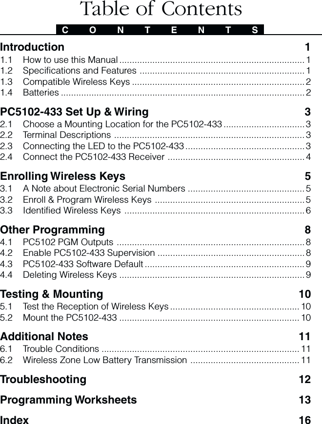
![5This section describes how to enroll wireless keys (WLS909-433 and WLS919-433). For moreinformation on these keys, read the instruction sheet included with each key.3.1 A Note about Electronic Serial NumbersAn electronic serial number (ESN) is printed on the back of each wireless key. ESNs areused to enroll the wireless keys with the PC5102-433 receiver.In order to reduce the occurrence of wireless keys with the same serial number, 6-digitserial numbers are now printed on the back of each wireless key. The 6-digit serialnumbers include hexadecimal digits. For instructions on programming hexadecimalnumbers, see your system Installation Manual, Section 4: How to Program.NOTENOTENOTENOTENOTE: 6-digit serial numbers are only supported on the following control panels:PC5020, PC501X v2.0 and higher, PC1555, PC5008 and PC580.The WLS909-433 and WLS919-433 keys have both a 5-digit and a 6-digit serialnumber printed on them. When connecting the PC5102-433 to a PC5010 v1.x panel,enter 5-digit serial numbers only. When connecting the PC5102-433 to a PC5020 orPC5015 v2.x and higher, PC5010 v2.0 and higher, PC1555, PC5008 or PC580 panelenter the 6-digit serial number.3.2 Enroll & Program Wireless KeysFor wireless keys to work on the system, you need to enroll them and then program thefunction buttons, if the default values are not the functions desired. Wireless keys arenot assigned to zones and require no zone programming. You can enroll up to 8wireless keys on the system.Enroll Wireless keys1. At a system keypad, enter [✱][8][Installer’s code] to go to the Installer’sProgramming section.2. Enter programming section [804].3. Enter a 2-digit number [41]-[48] to program the wireless key serial number.These numbers correspond to wireless key numbers 01- 08.4. Enter the key’s ESN. The entry must be six digits. If an older key with a 5-digit ESN is being enrolled, add the digit [0] to the beginning of the ESN.(E.g. ESN=61234, enter 061234)5. The key is now enrolled on the system. Record the serial number and theassigned slot number in the programming worksheets in the back of this manual.6. Repeat steps 3 - 5 until all wireless keys have been enrolled.7. (((((PC5020 / PC5020 / PC5020 / PC5020 / PC5020 / PC501PC501PC501PC501PC501XXXXX only) only) only) only) only) By default, all wireless keys are assigned toPartition 1. To assign keys to Partition 2, enable the appropriate options inprogramming section [91].NOTENOTENOTENOTENOTE: A wireless key can only be assigned to one partition.8. To exit press [#].Program the WLS909-433 or WLS919-433 Function ButtonsWLS909-433 and WLS919-433 wireless keys have four programmable functionbuttons. Default functions have been assigned, but you may program the functionsdesired. After the functions are programmed, when you press and hold one of thefour buttons for one second, the system will execute the programmed function.S E C T I O N 3Enrolling Wireless Keys](https://usermanual.wiki/Tyco-Safety-Canada/01PC5102/User-Guide-163399-Page-11.png)
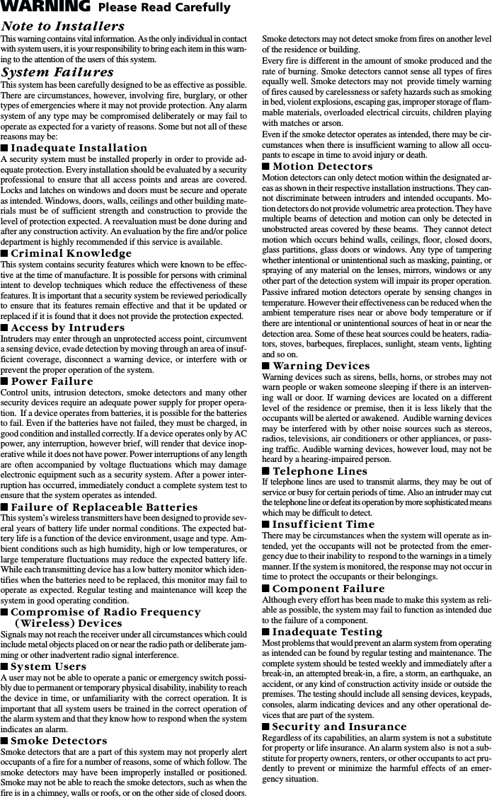
![6For systems using partitions (PC5020 / PC501X only): all wireless keys assigned toPartition 1 will have the four functions programmed in section [61]. All wireless keysassigned to Partition 2-8 will have the four functions programmed in section [62-68]. Forexample, if function button 1 in Section [61] is programmed for Stay arming, then pressingthe first button on wireless keys assigned to Partition 1 will Stay arm Partition 1.NOTENOTENOTENOTENOTE: Wireless keys will not work when the partition they are assigned to is beingaccessed for zone bypassing or programming.1. At a system keypad, enter [✱][8][Installer’s code].2. Enter programming section [804].3. Enter programming section [61] to [68] for partitions 1 to 8.4. For each of the 4 function buttons, enter the 2-digit number of the functionyou want to select. See the programming worksheets in the back of thismanual for a list of function key options.5. Record your programming choices in the worksheets in the back of the manual.6. To exit press [#].3.3 Identified Wireless KeysReporting by the system of openings/closings by individual wireless keys andcommand output [✱][7] activation by wireless key buttons may be supported oncertain control panels. To do this, the system will reserve access codes 17 – 24 forwireless keys 01-08 respectively. You must program one access code for eachwireless key (using [✱][5] access code programming) for this feature to workcorrectly.NOTENOTENOTENOTENOTE: Program these access codes on the system after you have connected thePC5102-433 to the Keybus (see section 2.4).Refer to your system Installation Manual for information on access code programming.Opening/Closing By Wireless Key ReportingNOTENOTENOTENOTENOTE: The Identified Wireless Key Closing option is only available with the PC5020 orPC501X v2.0 and higher, PC1555, PC5008, PC580 v2.0 and higher by turning section[015] Option 4 off.To enable the reporting of openings and closings by identified wireless keys:• Make sure the control panel is v2.0 or higher• Program a valid access code for each key• Program a closing and opening reporting code for each key’s access code• Turn off the Quick Arm option in section [015] option [4] of the control panelprogrammingTo ensure that an unidentified wireless key cannot disarm the system, turn off section[017], option [1] (in the control panel programming). This option is available in controlpanels with software version 2.1 or higher.W I R E L E S S D E V I C E S](https://usermanual.wiki/Tyco-Safety-Canada/01PC5102/User-Guide-163399-Page-12.png)
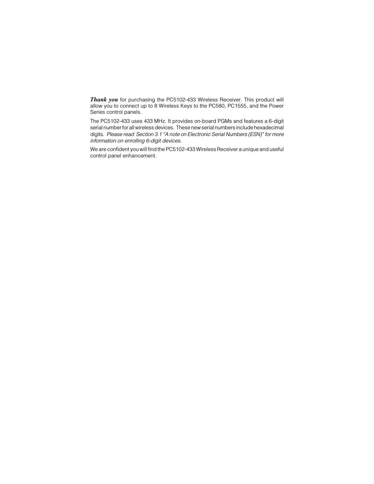
![7Command Output ActivationNOTENOTENOTENOTENOTE: The Identified Wireless Key Command Output Activation feature is only avail-able with the PC5020, PC501X, PC1555, PC5008 and PC580 v2.0 and higher.To enable command output activation by wireless keys, ensure that:• The control panel is v2.0 or higher• Program a valid access code for each key• Enable the PGM output attribute Requires Access Code for each PGMoutput programmed as [✱][7][1-4] in sections [141] to [154].Now that you have enrolled all the wireless keys, you will need to program the systemto work properly with the keys. See section 4 for more information.W I R E L E S S D E V I C E S](https://usermanual.wiki/Tyco-Safety-Canada/01PC5102/User-Guide-163399-Page-13.png)
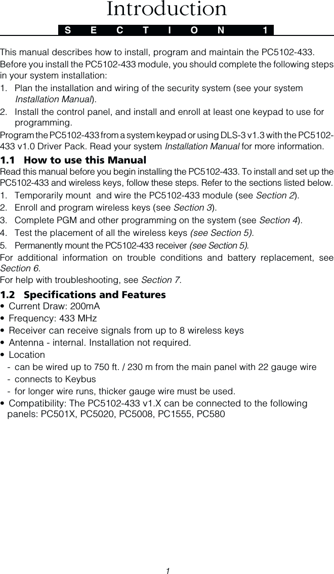
![84.1 PC5102 PGM OutputsThe PC5102 433 has two on-board Form C Relay PGM outputs. Each of these canbe individually programmed to either:1. Follow main panel PGM outputs 1 to 14.NOTE: Please refer to your System Installation Manual for available PGM outputs.NOTE: If the PC5102-433 is connected to the following panels, PC580/PC1555 allversions, PC5010 v1.x, WSS5010 1.0, 2.1, PC1565-2P v2.2 or PC5016 v1.x, the PC5102PGM outputs cannot be programmed to follow main panel PGM outputs 1 or 2.2. Activate for a programmable amount of time when a data packet is receivedfrom a wireless key programmed with option 31 or 32 and the PGM outputprogramming section [91] or [92] is programmed with option 15 (PC5102PGM pulse). The default for the two PGM activation time programmingsections [94] and [95] is 00 minutes and 05 seconds.3. Toggle state when a data packet is received from a wireless key programmedwith option 31 or 32 and the PGM output programming section [91] or [92] isprogrammed with option 16 (PC5102 PGM Toggle).4.2 Enable PC5102-433 SupervisionThe control panel will supervise the PC5102-433 receiver via the Keybus after at leastone key has been enrolled on the module (see section 3.2 “Enrolling Wireless Keys”).To activate module supervision, after you enroll the first key(s):1. Exit and then re-enter installer’s programming.2. Enter programming section [902]. Wait approximately one minute.3. To exit press [#].The system will generate a General System Supervisory trouble if the module isremoved from the Keybus. If you need to remove the PC5102-433 module from anexisting system, you will have to disable supervision of the PC5102-433.NOTENOTENOTENOTENOTE: Deleting all wireless keys from the PC5102-433 or defaulting the PC5102-433will cause a supervisory fault.To disable PC5102-433 supervision:1. Disconnect the PC5102-433 from the Keybus2. Enter [✱][8][Installer Code].3. Enter [902]. The control panel will clear all supervision and re-scan the system forconnected modules. The scan will take approximately one minute.4. To exit press [#].To review which modules the control panel is currently supervising:1. Enter [✱][8][Installer’s Code]2. Enter [903] to display all modules. On LED keypads, light [17] will indicatethat the PC5102-433 is present on the system. On LCD keypads, scroll untilthe module name appears on the display.3. To exit press [#].S E C T I O N 4Other Programming](https://usermanual.wiki/Tyco-Safety-Canada/01PC5102/User-Guide-163399-Page-14.png)
![9If the PC5102-433 module does not show on the keypad, one of the followingconditions may be present:• the module is not connected properly to the Keybus• there is a problem with the Keybus wiring run• the module does not have enough power• no keys have been enrolled on the PC5102NOTE: The PC5102-433 will be supervised and displayed as a PC5132.4.3 PC5102-433 Software DefaultReturning the PC5102-433 programming to factory default settings is a quick way toremove all the enrolled wireless keys from the system and reset all the programmingin section [804].NOTENOTENOTENOTENOTE: Performing this procedure will not change any programming sections ex-cept [804]. Resetting the control panel to factory default settings will not return thePC5102-433 module to factory default settings.To restore the PC5102-433 programming to the factory default settings:1. Enter [✱][8] [Installer’s Code].2. Enter programming section [996].3. Enter the Installer’s Code, followed by [996] again. The programming for thePC5102-433 will be restored to its factory default settings.4. To continue programming the unit, exit installer’s programming by pressing [#]and then re-enter installer’s programming by entering [✱][8] [Installer’s Code].For instructions on restoring the default programming of the control panel or anyother connected module, see your system Installation Manual.4.4 Deleting Wireless KeysTo remove a wireless key from the system, follow the guideline for enrolling a wirelesskey (see section 3.2). Program the ESN as [000000]. The wireless key for the zonewill be removed.Now that you have completed all PC5102-433 related programming, you can testand mount the receiver. See Section 5 for more information.O T H E R P R O G R A M M I N G](https://usermanual.wiki/Tyco-Safety-Canada/01PC5102/User-Guide-163399-Page-15.png)
![11Additional NotesS E C T I O N 66.1 Trouble ConditionsThe control panel always watches for possible trouble conditions. If a troublecondition occurs, the keypad “Trouble” light will turn on and the keypad will beep.Press [✱][2] to display the trouble conditions.The following trouble conditions apply to the PC5102-433 and/or any enrolled wirelesskeys.General System Tamper - This trouble is generated when the PC5102-433plastic cover is removed.General System Supervisory - This trouble will be generated if the panel losescommunication with any module connected to the Keybus. The event buffer willlog a detailed description of the event.Device Low Battery - This trouble is generated when a wireless device exhibits alow battery condition. Press [7] one, two, or three times to view which devicesare experiencing battery failure. An LED keypad will indicate battery failureusing zone lights 1 to 8.Tamper SwitchesThere is one tamper switch on the PC5102-433 board. Removing the plastic coverwill cause a general system tamper.6.2 Wireless Zone Low Battery TransmissionWithin any transmission, the device will indicate the status of the battery. If a batteryis low, the system will indicate a Device Low Battery trouble.The system will delay reporting the event to the central station for the number of daysprogrammed for Zone Low Battery Transmission Delay in section [370]. This willprevent unnecessary reporting of the event if the user has been instructed on howto replace batteries.Replacing Batteries in Wireless Devices1. Remove the cover of the device from its back plate.2. Refer to the battery installation instructions on the installation sheet of eachcomponent. Be sure to note the proper orientation of the batteries as youinstall them.3. When the fresh batteries are in place, re-attach the cover to the back plate. Thebattery trouble will clear when any button is pressed after the installation ofthe new batteries, the device should function normally.NOTENOTENOTENOTENOTE: When batteries in one device need to be replaced, the batteries in all de-vices may need to be replaced at the same time.](https://usermanual.wiki/Tyco-Safety-Canada/01PC5102/User-Guide-163399-Page-17.png)
![13[804] 5102-433 Wireless Expansion Programming• 6-digit entry is required. See Section 3.1 “A note on Electronic SerialNumbers” for details on programming 6-digit serial numbers.Programming WorksheetsS E C T I O N 8Wireless Key Serial NumbersDefault = 000000[41] Key 01 l_____l_____l_____l_____l_____l_____l[42] Key 02 l_____l_____l_____l_____l_____l_____l[43] Key 03 l_____l_____l_____l_____l_____l_____l[44] Key 04 l_____l_____l_____l_____l_____l_____l[45] Key 05 l_____l_____l_____l_____l_____l_____l[46] Key 05 l_____l_____l_____l_____l_____l_____l[47] Key 07 l_____l_____l_____l_____l_____l_____l[48] Key 08 l_____l_____l_____l_____l_____l_____lyrtnEyrtnE yrtnE yrtnEyrtnEnoitpircseDyeKnoitpircseDyeK noitpircseDyeK noitpircseDyeKnoitpircseDyeKyrtnEyrtnE yrtnE yrtnEyrtnEnoitpircseDyeKnoitpircseDyeK noitpircseDyeK noitpircseDyeKnoitpircseDyeK0000000000yeKlluN 7171717171[✱syawA/yatSetavitcaeR]1[]20-1020-10 20-10 20-1020-10esUerutuFroF8181818181esUerutuFroF3030303030mrAyatS 9191919191[✱3#tuptuOdnammoC]3[]7[]4040404040mrAyawA 0202020202esUerutuFroF5050505050[✱mrAyrtnE-oN]9[] 1212121212[✱4#tuptuOdnammoC]4[]7[]6060606060[✱FFO/NOemihC]4[] 62-2262-22 62-22 62-2262-22esUerutuFroF7070707070[✱tseTmetsyS]4[][]6[]7272727272)FFO(mrasiD21-8021-80 21-80 21-8021-80esUerutuFroF8282828282mralAeriF3131313131[✱1#tuptuOdnammoC]1[]7[]9292929292mralAyrailixuA4141414141[✱/2#tuptuOdnammoC]2[]7[]teseRrosneS0303030303mralAcinaP5151515151esUerutuFroF1313131313esluP1MGP2015CP6161616161[✱tixEkciuQ]0[] 2323232323esluP2MGP2015CP](https://usermanual.wiki/Tyco-Safety-Canada/01PC5102/User-Guide-163399-Page-19.png)
![14P R O G R A M M I N G W O R K S H E E T SWireless Key OptionsPartition 1 Wireless Key Options[61] Function Key 1 03 l____l____lFunction Key 3 27 l____l____lFunction Key 2 04 l____l____lFunction Key 4 30 l____l____lPartition 2 Wireless Key Options[62] Function Key 1 03 l____l____lFunction Key 3 27 l____l____lFunction Key 2 04 l____l____lFunction Key 4 30 l____l____lPartition 3 Wireless Key Options[63] Function Key 1 03 l____l____lFunction Key 3 27 l____l____lFunction Key 2 04 l____l____lFunction Key 4 30 l____l____lPartition 4 Wireless Key Options[64] Function Key 1 03 l____l____lFunction Key 3 27 l____l____lFunction Key 2 04 l____l____lFunction Key 4 30 l____l____lPartition 5 Wireless Key Options[65] Function Key 1 03 l____l____lFunction Key 3 27 l____l____lFunction Key 2 04 l____l____lFunction Key 4 30 l____l____lPartition 6 Wireless Key Options[66] Function Key 1 03 l____l____lFunction Key 3 27 l____l____lFunction Key 2 04 l____l____lFunction Key 4 30 l____l____lPartition 7 Wireless Key Options[67] Function Key 1 03 l____l____lFunction Key 3 27 l____l____lFunction Key 2 04 l____l____lFunction Key 4 30 l____l____lPartition 8 Wireless Key Options[68] Function Key 1 03 l____l____lFunction Key 3 27 l____l____lFunction Key 2 04 l____l____lFunction Key 4 30 l____l____l[91] Wireless Keys (1-8) Partition AssignmentsDefault = 01Wireless Key 01 l________l ________lWireless Key 02 l________l ________lWireless Key 03 l________l ________lWireless Key 04 l________l ________lWireless Key 05 l________l ________lWireless Key 06 l________l ________lWireless Key 07 l________l ________lWireless Key 08 l________l ________l](https://usermanual.wiki/Tyco-Safety-Canada/01PC5102/User-Guide-163399-Page-20.png)
![15P R O G R A M M I N G W O R K S H E E T SEntry Description00 Null (No Operation)01 Main Panel PGM102 Main Panel PGM203 PC5208 PGM304 PC5208 PGM405 PC5208 PGM506 PC5208 PGM607 PC5208 PGM708 PC5208 PGM809 PC5208 PGM910 PC5208 PGM1011 PC5204 PGM1112 PC5204 PGM1213 PC5204 PGM1314 PC5204 PGM1415 PC5102 PGM Pulse (local)16 PC5102 PGM Toggle (local)[92] PC5102 PGM1 Output OptionDefault 01Default 01Default 01Default 01Default 01PGM1 Output Option l________l ________l[93] PC5102 PGM2 Output OptionDefault 02Default 02Default 02Default 02Default 02PGM2 Output Option l________l ________l[94] PC5102 - PGM1 Output Activation TimeDefault 00Default 00Default 00Default 00Default 00PGM1 Output Activation Time (Minutes) l________l ________lDefault 05Default 05Default 05Default 05Default 05PGM1 Output Activation Time (Seconds) l________l ________l[95] PC5102 - PGM2 Output Activation TimeDefault 00Default 00Default 00Default 00Default 00PGM2 Output Activation Time (Minutes) l________l ________lDefault 05Default 05Default 05Default 05Default 05PGM2 Output Activation Time (Seconds) l________l ________lNOTE: Sections [94] and [95] have a valid minimum programmable value of 00minutes 01 seconds, and a valid maximum programmable value of 99 minutes 99seconds.](https://usermanual.wiki/Tyco-Safety-Canada/01PC5102/User-Guide-163399-Page-21.png)