Tyco Safety Canada 02CL3050 Alarm System Wireless Communicator User Manual CL3050 eng im 2903453r001 QuickStart
Digital Security Controls Ltd. Alarm System Wireless Communicator CL3050 eng im 2903453r001 QuickStart
UserManual.wiki
>
Tyco Safety Canada
>
02CL3050 User Manual
Users Manual
Navigation menu
Upload a User Manual
Namespaces
Wiki Guide
HTML
PDF
Info
Views
User Manual
Discussion / Help
Navigation
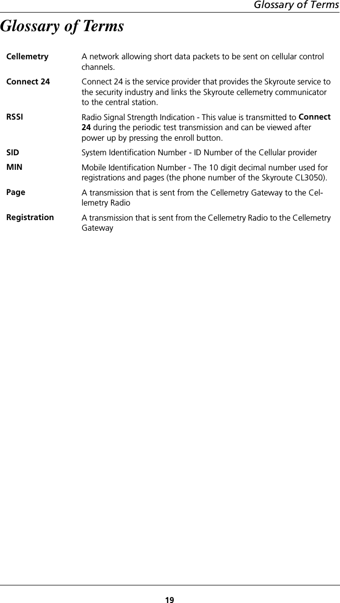
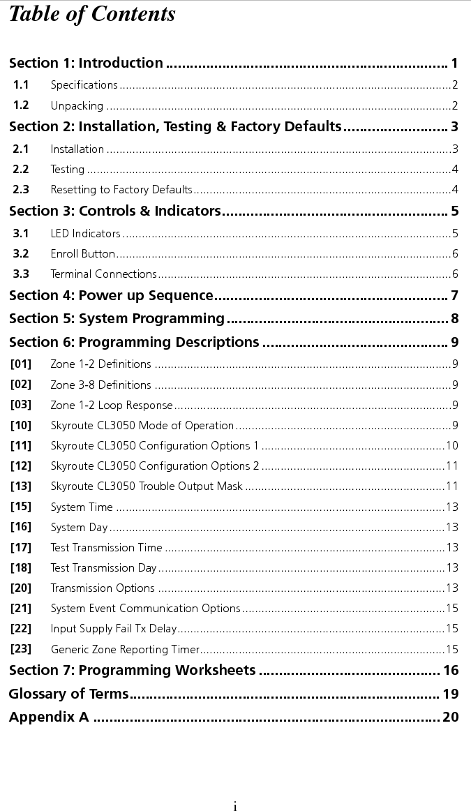
![iTable of ContentsSection 1: Introduction ...................................................................... 11.1 Specifications.......................................................................................................21.2 Unpacking ...........................................................................................................2Section 2: Installation, Testing & Factory Defaults.......................... 32.1 Installation ...........................................................................................................32.2 Testing .................................................................................................................42.3 Resetting to Factory Defaults................................................................................4Section 3: Controls & Indicators........................................................ 53.1 LED Indicators ......................................................................................................53.2 Enroll Button........................................................................................................63.3 Terminal Connections...........................................................................................6Section 4: Power up Sequence.......................................................... 7Section 5: System Programming....................................................... 8Section 6: Programming Descriptions .............................................. 9[01] Zone 1-2 Definitions ............................................................................................9[02] Zone 3-8 Definitions ............................................................................................9[03] Zone 1-2 Loop Response......................................................................................9[10] Skyroute CL3050 Mode of Operation...................................................................9[11] Skyroute CL3050 Configuration Options 1 .........................................................10[12] Skyroute CL3050 Configuration Options 2 .........................................................11[13] Skyroute CL3050 Trouble Output Mask ..............................................................11[15] System Time ......................................................................................................13[16] System Day ........................................................................................................13[17] Test Transmission Time .......................................................................................13[18] Test Transmission Day.........................................................................................13[20] Transmission Options .........................................................................................13[21] System Event Communication Options...............................................................15[22] Input Supply Fail Tx Delay...................................................................................15[23] Generic Zone Reporting Timer............................................................................15Section 7: Programming Worksheets ............................................. 16Glossary of Terms............................................................................. 19Appendix A ...................................................................................... 20](https://usermanual.wiki/Tyco-Safety-Canada/02CL3050/User-Guide-270119-Page-5.png)
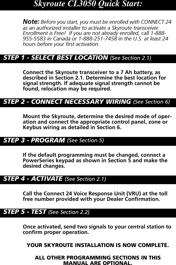
![2 Installation, Testing & Factory Defaults32 Installation, Testing & Factory Defaults2.1 Installation1 Determine The Operating mode required (see section [03])The operating mode (modes 1, 2, or 3) will determine how the unit is to be wired up. Refer to section 6, Programming Descriptions, section [10] for available options and for programming defaults.2 Determine the Mounting LocationSelect a mounting location in a dry, protected area. The mounting location should be positioned so that it is at least 30 cm. away from physical contact with any person.Note: Do Not exceed the following recommendations for wire run distances• Keybus and zone wiring should be run using minimum 22 gauge quad (0.5mm). Two pair twisted is preferred. • a keypad, PC5108, or zone wiring can not exceed 1,000'/305m (in wire length) from the Skyroute CL3050.• Shielded wire is not necessary unless wires are run in an area that may present excessive RF noise or interference.•Refer to section 6, Programming Descriptions, section [10] for zone wir-ing details.Note: Generally, the higher the location and the closer that the Skyroute CL3050 is to an outside wall, the better the signal strength will be.3Checking Signal Strength• Remove front cover• Connect Battery to the RED and BLK flying leads.• Connect AC Power source or 12 VDC to RED & BLK terminals.• Allow unit to power upNote: The unit does not need to be enrolled with Connect 24 to check sig-nal strength.• When the green LED stops flashing, press and release the enroll button.• Ensure that Radio Signal Strength Indication (RSSI) is greater than the mini-mum acceptable level as indicated below. If the signal level is not accept-able, reposition and retest the Skyroute CL3050 until an acceptable signal strength is found.Red LED Yellow LED Green LED Signal StrengthOnOnOnOnOnFlashOnOnOnFlashOffOffOnFlashOffOffOffOff>87%69-87%*52-68%34-51%16-33%0-15%*Minimum recommended signal strength for enrollment4 Route Wiring to Mounting LocationRoute wiring from the hardwired zones or control panel as required. Note: Route wiring through conduit to a junction box if possible. Mount the Skyroute Panel.](https://usermanual.wiki/Tyco-Safety-Canada/02CL3050/User-Guide-270119-Page-9.png)
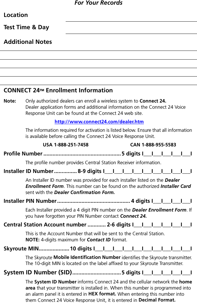
![Skyroute CL3050 Standalone Wireless Communicator45 Mount Unit• Remove the front cover if required• Disconnect flying leads from battery and power leads from the RED and BLK terminals (if connected).• Remove two screws securing battery clamp. Remove battery• Mount backplate of unit to wall or over electrical junction box using the four screws provided.Note: DO NOT connect the battery to the flying leads and AC or DC power to the terminal strip until all other wiring connections are completed. • Route wiring through the access holes provided and connect to terminal strip.• power up unit by connecting battery and power source.6 Enroll UnitCall Connect 24 and Enroll the Skyroute CL3050. Refer to page (ii) for contact information and a list of information required to complete the enrollment with the Connect 24 Voice Response Unit.2.2 Te s t i n gProgram Mode: If you have wired the unit to power up in the programming mode. Follow the steps outlined in Section 6, Programming Descriptions and record the program settings in Section 7, Programming Worksheets.Test Transmission - Pressing and holding the enroll button for 2 seconds will send a test transmission to the central station via Connect 24. Refer to Enrol Button in Section 3, Controls and indicators for test transmission details.Mode 1: Disable the telephone line connected to the control panel. Simulate Burglar and Fire Zone violation. Verify that the Skyroute CL3050 transmits the events to the central station.Mode 2 & 3: Simulate Faults, Tampers, and Zone violations in accordance with the settings outlined in Sections 6, Programming Descriptions. Verify that the Skyroute CL3050 transmits the events to the central station.2.3 Resetting to Factory DefaultsNote: Resetting to factory defaults is required to change mode of operation. • Remove Power from the Skyroute CL3050; disconnect battery and control panel if applicable (mode 1).• Disconnect all wiring from the YEL and GRN terminals.• Connect a jumper wire between the YEL and GRN terminals.• Apply power to the system.Note: When the hardware default has been completed; the yellow, green and red LEDs will flash on and off continuously. • Remove power from the system.Note: To resume communications with Connect 24, Section [11], Option 6 must be set to ON. To do this; the system must be powered up in pro-gramming mode. Refer to Section 5 System Programming.• Reconnect all original wiring and reapply power to the system.• Test System - Refer to Section 2.2](https://usermanual.wiki/Tyco-Safety-Canada/02CL3050/User-Guide-270119-Page-10.png)
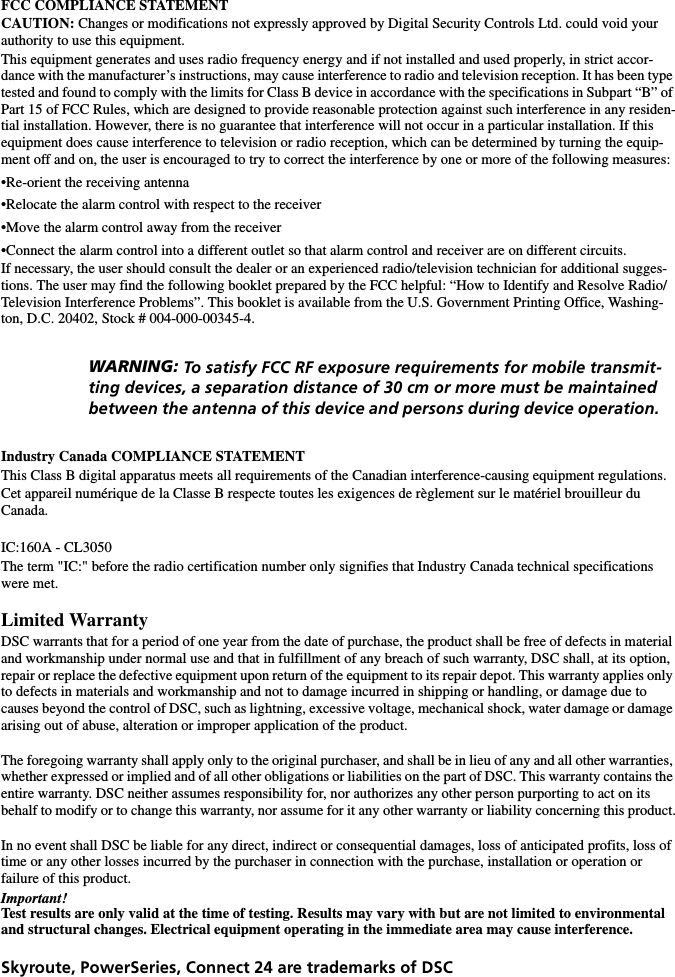
![Skyroute CL3050 Standalone Wireless Communicator85 System ProgrammingThe Skyroute CL3050 is programmed using a PowerSeries keypad. Refer to Section 1.1 Specifications.Note: Power down the Skyroute CL3050 when connecting or removing other Keybus modules from the system. If the Skyroute CL3050 is con-nected to a control panel (mode 1), the control panel must also be powered down.1. Connect keypad Keybus connections to the RED, BLK, YEL and GRN termi-nals of the Skyroute CL3050. 2. Connect a +12VDC supply across the RED and BLK terminals. Upon detecting the keypad on power up, the Skyroute CL3050 will begin driving Keybus and will blank the keypad with all LEDs and icons off. 3. Press the star [*] key to gain access to the programming section. Programming is done with a 2-digit section entry. When programming is complete, power down the Skyroute CL3050 and remove the keypad.To KeybusConnectionson KeypadNot ConnectedRED BLK YEL GRN COM PGM](https://usermanual.wiki/Tyco-Safety-Canada/02CL3050/User-Guide-270119-Page-14.png)
![6 Programming Descriptions96 Programming Descriptions[01] Zone 1, 2 Definitions Modes 2, 3When the Skyroute CL3050 is in Mode 2 or 3, there are 14 options that can be programmed as zone types. All of the zone types with the exception of 00 (null zone) and 13 (TLM monitor) are straightforward. Since all the zones are 24-hour type zones, selecting any listed zone type will simply select which identifier should be used for reporting the alarm. Programming a zone as 00 (null zone) will disable the zone input on the Skyroute CL3050 or PC5108 hardware. Pro-gramming any zone as type 13 will disable all communications unless that zone input is closed (short condition).Note: Do NOT program more than 1 TLM zone type on the Skyroute CL3050.Default - [01] zones 1 & 2[02] Zone 3 - 8 Definitions Mode 3This allows programming of the six additional zone definitions when operating in mode 3 with a PC5108 zone expander. See section [01] for detailsDefault - [01] zones 3 - 8[03] Zone 1, 2 Loop Response Modes 2This entry determines how quickly a zone will respond to changes in state.Note: This does not affect zones on a PC5108 zone expander card.Default - 05 (0.5 seconds) 01-FF Hex x 0.1 seconds.[10] Skyroute CL3050 Mode of Operation[01] Mode 1 - Bell Follower OperationIn this mode, the YEL terminal is con-nected to the bell output of a control panel. The Skyroute CL3050 moni-tors the output for burglary and fire cadences and transmits the appropri-ate events. For any type of pulsed cadence, the Skyroute CL3050 will send a generic Fire event, for any steady bell the Skyroute CL3050 will send a generic Burglary event. The GRN terminal is a trouble input which can be connected to a system output to alert the Skyroute CL3050 of a system TLM fault. This will enables the Skyroute CL3050 to be used as a back-up communi-cator only. If not used, this input must to connected to COM. The bell cadence will be determined as follows:• Bell must be on for longer then 300mS to be considered a "pulse"• Bell must be on for 3 seconds continuous to be considered "steady"• Bell must be off for 3 seconds continuous to be considered "silenced"• Bell must pulse on and off 3 times to be considered "pulsed", 3rd off-time will trigger eventBell Report Code GroupPulsedSteadyFA98BA98FireBurglaryInput Voltage9-12V or VAC DCBell InputTLM InputSystem CommonTrouble OutputRED BLK YEL GRN COM PGM](https://usermanual.wiki/Tyco-Safety-Canada/02CL3050/User-Guide-270119-Page-15.png)
![Skyroute CL3050 Standalone Wireless Communicator10[02] Mode 2 - (2) 24-Hour ZonesIn this mode, both the YEL and GRN terminals on the Skyroute CL3050 will be used as zone inputs. These zones will support the DSC standard EOL configura-tion and loop response. Pro-gramming sections will allow the installer to change the default zone types and attributes. The Skyroute CL3050 will continu-ously monitor these zones and transmit any alarms that occur to the central sta-tion.[03] Mode 3 - (8) 24-Hour ZonesIn this mode, the Skyroute CL3050 is connected to a PC5108 zone expander using the corresponding RED, BLK, YEL and GRN terminals. The Skyroute CL3050 will drive the Keybus to communicate with the PC5108. A +12VDC sup-ply connected to the RED and BLK terminals is required when using this mode. The Programming sections will allow the installer to change the default zone types and attributes. The Skyroute CL3050 will continu-ously monitor these zones and transmit any alarms that occur to the central station.Note: This configuration can not be used with an AC supply.Note: Jumpers on the PC5108 must be set as follows:J1J2J3ONOFFONJ4J5J6OFFOFFONDefault - [01 -03] dependant on start up configuration[11] Skyroute CL3050 Configuration Options 1Option 1 - A Channel Selected/ B Channel Selected. All ModesThis Option determines whether cellular channel “B” or channel “A” is used. In Canada, Channel B is used (Default). In the USA refer to the SID list for the chan-nel of the cellular service provider in your area. Default - Channel BOption 2 - Normally Closed Loops/ End-of-line Resistors Mode 2, 3Normally Closed Loops can be wired as shown. Multiple Normally Closed contacts can be wired in series. For Double or Single EOL resistors this option must be set to OFF. Default - Normally Closed (N/C) Loops.Option 3 - Double EOL Resistors/Single EOL Resistors Mode 2, 3This option selects Double EOL resistors (ON) or Single EOL resistors (OFF) wired as indicatedInput Voltage9-12V or VAC DCZone 1 InputZone 2 InputZone CommonTrouble OutputRED BLK YEL GRN COM PGMTo KeybusConnectionson PC5108System CommonTrouble OutputRED BLK YEL GRN COM PGM](https://usermanual.wiki/Tyco-Safety-Canada/02CL3050/User-Guide-270119-Page-16.png)
![6 Programming Descriptions11Single EOL resistors allows the use of N/C and/or Normally Open contacts.Double EOL resistors allows the zone to be monitored for fault, tamper, secure and violated condi-tions. Only Normally Closed contacts can be used in this configurationNote: Option 2 must be set to OFF to enable these options. Default - OFFOption 4 - Test Once a Day Enabled/Disabled All ModesAllows transmission test daily. Default - Disabled.Option 5 - Test Once a Week Enabled/Disabled All ModesAllows transmission test weekly.Note: This option will be overridden If option 4 is set for daily test transmissions. Default - Enabled.Option 6 - Enrolled with Connect 24 /Not Enrolled All ModesThis option is set automatically during the enrollment procedure with Connect 24. IF the Skyroute CL3050 is reset to the default settings this option must be set to ON for the Skyroute CL3050 to resume communications. Default - Not Enrolled.Options 7, 8 - System Use All ModesCaution: Do NOT change these settings unless it is requested by DSC technical support personnel. Default - OFF.[12] Skyroute CL3050 Configuration Options 2Option 1 - Swinger Shutdown Enabled/Disabled Modes 2, 3This option limits the number of alarm events transmitted per zone to 8 until the counter has been reset (counter automatically resets at midnight), then event transmissions will resume. Default - Enabled Note: Tampers and Faults will be counted unless they are disabled in section [20].[13] Skyroute CL3050 Trouble Output mask All ModesThe PGM output is dedicated for trouble indications. If a control panel is not monitoring the Skyroute CL3050, an LED or a buzzer can be connected between this terminal and the RED terminal for a trouble indication. The PGM terminal switches low from an open-collector state. Connect to the control panel using a single EOL resistor configuration.5.6KΩC Zx 5.6KΩC Zx 5.6KΩC Zx 5.6KΩTam p erContactC Zx 5.6KΩ5.6KΩ5.6KΩC Zx](https://usermanual.wiki/Tyco-Safety-Canada/02CL3050/User-Guide-270119-Page-17.png)
![Skyroute CL3050 Standalone Wireless Communicator12.Note: A relay may be required for proper operation in other configurations. See paragraph 3.3 Terminal Connections.Option 1 - Low battery All ModesIf the battery voltage drops below 5.72VDC a trouble will be indicated until the battery voltage rises to 5.87VDC. Default - ONOption 2 - Input Supply Failure All ModesIf AC power is absent or if DC power drops below 8.8VDC on the RED and BLK terminals, this trouble is indicated. Default - ONOption 3 - Zone Fault/Tamper (DEOL Only) Modes 2, 3A trouble will be indicated if any zone reports a fault or tamper condition. In Sec-tion [11], Option [2] must be set to OFF and Option [3] must be set to ON for this option to be enabled. Default - OFFOption 4 - No Service Available All ModesThis trouble is indicated If the system is unable to detect cellular service.Default - ONOption 5 - Radio Failure All ModesThis trouble is indicated if there is an internal fault with the cellular radio. Default - ONOption 6 - PC5108 Failure Mode 3This trouble is indicated if a PC5108 supervisory or Keybus fault occurs. Note The PC5108 tamper is communicated only, therefore it can only be enabled by turning on section 20 option 7 and section 21 option 5. There is no local annunciation for this event.Default - ONOption 7 - Failure to Communicate (FTC) All ModesThis trouble will be indicated if no acknowledgement has been received from Connect 24 after three attempts. Default - ONOption 8 - Skyroute CL3050 Tamper All ModesThis trouble will be indicated if the cover is removed from the Skyroute CL3050 activating the on-board tamper switch. Default - OFF Zx COM Control PanelRED BLK YEL GRN COM PGM5.6KΩSkyroute CL3050](https://usermanual.wiki/Tyco-Safety-Canada/02CL3050/User-Guide-270119-Page-18.png)
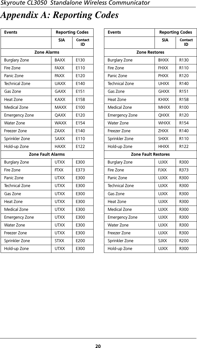
![6 Programming Descriptions13[15] System Time All ModesWhen the time and day have been programmed, the values are saved and are used as the current time and day whenever the Skyroute CL3050 does a power up. Time and day programming is only required if the installer desires the Sky-route CL3050 to test transmit at a specific time and/or day. There is no "loss of time" trouble on the Skyroute CL3050.Default - 0000 - 2359Note If AC Power is detected, it will be used to provide the time base for the internal clock. If AC power is not detected the internal clock will auto-matically use the crystal time base.[16] System Day of the Week All ModesSee section [15]. Option 1. Default - ONOption 2 - 8. Default - OFF[17] Test Transmission Time All ModesWhen the Skyroute CL3050 is powered up for the first time, or after a default reset; it will check if the test transmission time and day are programmed. If they are not, a random time (0000 - 2359) will be programmed into this location. The Skyroute CL3050 will randomly generate this value.Note: Due to traffic volume, when selecting test transmission times, select a time that is not on the :30 minute mark (e.g., 02:24, 04:07).[18] Test Transmission Day All ModesWhen the Skyroute CL3050 is powered up for the first time, or after a default, it will check if the test transmission time and day are programmed. If they are not, a random day (Sunday-Saturday) will be programmed into this location. The Sky-route CL3050 will randomly generate this value. Because one test transmission weekly is the most common configuration, this will allow the installer to setup the Skyroute CL3050 without keypad programming.Option 1-8. Default - [Random] - One only will be enabled.[20] Transmission Options All ModesWhen the following options are enabled the reporting codes listed in Appendix A are sent to Connect 24.Options 1, 2 - Zone Alarm/Zone Alarm Restores Modes 2, 3When a zone is violated or restored, the reporting codes listed in Appendix A will be sent.Note: If generic reporting is enabled and multiple alarms occur during the delay programmed in Section [23], only one alarm reporting code will be sent.Note: Zone alarm restorals enabled with generic zone reporting enabled can cause unpaired events to be sent to Connect 24.Option 1. Default - ON, Option 2. Default - OFF](https://usermanual.wiki/Tyco-Safety-Canada/02CL3050/User-Guide-270119-Page-19.png)
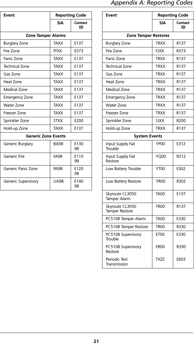
![Skyroute CL3050 Standalone Wireless Communicator14Options 3, 4 - Zone Fault, Zone Fault Restores Modes 2, 3When the system sees a short circuit across any zone, a zone fault is generated.DEOL resistors are required for zone fault reporting. In Section [11], Option [2] must be set to OFF and Option [3] must be set to ON; In Section [13], Option 3 must be set to ON and the Skyroute CL3050 must be operating in mode 2 or 3.Option 3. Default - OFF, Option 4. Default - OFFOptions 5, 6 - Zone Tamper, Zone Tamper Restores Modes 2, 3When the system sees an open circuit across any zone a zone tamper is gener-ated. DEOL resistors are required for zone tamper reporting. In Section [11], Option [2] must be set to OFF and Option [3] must be set to ON. In Section [13], Option [3] must be set to ON and the Skyroute CL3050 must be operating in mode 2 or 3.Option 5. Default - OFF, Option 6. Default - OFFOption 7 - System Maintenance Events All ModesWhen this option is enabled, the maintenance events enabled in Section [21] are transmitted using the codes listed in appendix A.Default - ON,Option 8 - Generic Zones Modes 2, 3The Skyroute CL3050 supports generic and detailed zone alarm reporting. By default, the Skyroute CL3050 will be in generic zone reporting mode. When in this mode, all zone types are divided into four reporting groups; BA Burg, FA Fire, PA Panic, UA Technical. If any zone from this group initiates a transmission, the generic reporting code for this event is sent, additional violations from other zones from the same group will be ignored until that group's timer has expired. See table below for zone type grouping.ZoneTyp eDetailed Reporting CodeGeneric Reporting CodeNullBurglaryFirePanicTechnicalGasHeatMedicalEmergencyWaterFreezerSprinklerHold-up-BAFAPAUAGAKAMAQAWAZASAHA-BAFAPAUAUAFAPAPAUAUAUAPAEach zone group has it's own timer. The default time is 5 minutes and is pro-grammed in Section [23]. If any zone in a group initiates an event, the timer will start running and the generic event will be sent. If any additional zones from the same group initiate an event before that group's timer expires, the event will be ignored. This generic zone reporting mode only applies to zone alarms. Alarm restorals, tamper/tamper restorals and fault/fault restorals are not grouped together into generic reporting groups.](https://usermanual.wiki/Tyco-Safety-Canada/02CL3050/User-Guide-270119-Page-20.png)
![6 Programming Descriptions15The generic identifier will be sent with 98 as it's zone number, this is a special combination recognized by Connect 24 as a generic event. When the generic zone reporting toggle is disabled, each zone alarm for each zone type will then send it's own identifier. Default - ON.[21] System Event Communication OptionsNOTE: Section [20], Option [7] must be enabled for these events to be communicated.Option 1 - Input Supply Failure All ModesIf AC power is absent or if DC power drops below 8.8VDC on the RED and BLK terminals, a trouble will be sent after the delay programmed in section [22] has expired. Default - ON,Option 2 - Low Battery All ModesIf the battery voltage drops below 5.72VDC a trouble will be sent to Connect 24. When the battery voltage rises to 5.87VDC the system will send a restore. Default - ON.Option 3 - Skyroute CL3050 Tamper All ModesRemoving the cover on the Skyroute CL3050 will send a tamper reporting code to Connect 24. Default - OFF.Option 4 - PC5108 Module Fault Mode 3Indicates a Keybus communications fault condition.Default - OFF.Option 5 - PC5108 Tamper Mode 3Removing the cover on the PC5108 will send a tamper reporting code to Con-nect 24. Default - OFF.[22] Input Supply Fail TX Delay All ModesThis value determines the delay (default 0700 = 7 hrs) before an input supply fail-ure reporting code is sent if programmed. See Section [21], Option [1] and Sec-tion [20], Option [2]. Default - 0700 (=7 hrs)[23] Generic Zone Reporting Timer Modes 2, 3This hex value determines the delay before a generic zone reporting code is sent, if programmed in Section 20 Option 8.Note: There are four separate timers for Burglary, Fire, Panic and Supervisory; the delay programmed is the same for each timer. Default - 1E (300 seconds / 5 minutes) Range equals 01-FF Hex seconds x 10](https://usermanual.wiki/Tyco-Safety-Canada/02CL3050/User-Guide-270119-Page-21.png)
![Skyroute CL3050 Standalone Wireless Communicator167 Programming WorksheetsZone Definitions (For Sections [01] -[02])00 Null Zone (Not Used)01 Burglary02 Fire03 Panic04 Technical05 Gas06 Heat07 Medical08 Emergency09 Water10 Freeze 11 Sprinkler12 Hold-up13 TLM Monitor (1 zone max.)[01] Zone 1-2 Definitions Default Default01 I___I___I Zone 1 01 I___I___I Zone 2[02] Zone 3-8 DefinitionsDefault Default01 I___I___I Zone 3 01 I___I___I Zone 401 I___I___I Zone 5 01 I___I___I Zone 601 I___I___I Zone 7 01 I___I___I Zone 8[03] Zone 1-2 Loop Response 01-FF (Hex 0.1 second increments), mode 2 onlyDefault Default05 I___I___I Zone 1 05 I___I___I Zone 2[10] Skyroute CL3050 Mode of OperationDefault01 I___I___I 01 - Bell Follower, 02 - 2 Zone, 03 - 8 zone (PC5108 ) [11] Skyroute CL3050 Configuration Options 1Default Opt Option On Option OffOFF I___I 1A Channel selected B Channel selectedON I___I 2Normally Closed Loops End-of-Line ResistorsOFF I___I 3Double End-of-Line Resistors Single End-of-Line ResistorsOFF I___I 4Test Once a Day Enabled DisabledON I___I 5Test Once a Week Enabled DisabledOFF I___I 6Enrolled with Connect 24 Not Enrolled with Connect 24 OFF I___I 7 System Use - Caution: Do not changeOFF I___I 8 System Use - Caution: Do not change[12] Skyroute CL3050 Configuration Options 2Default Opt Option On Option OffON I___I 1 Swinger Shutdown Enabled Swinger Shutdown DisabledON I___I 2-8 For Future Use](https://usermanual.wiki/Tyco-Safety-Canada/02CL3050/User-Guide-270119-Page-22.png)
![7 Programming Worksheets17[13] Skyroute CL3050 Trouble MaskDefault Opt Option On Option OffON I___I 1Low Battery DisabledON I___I 2Input Supply Failure DisabledOFF I___I 3Zone Fault/Tamper (DEOL only) DisabledON I___I 4No Service Available DisabledON I___I 5Radio Failure DisabledON I___I 6PC5108 Failure DisabledON I___I 7Failure to Communicate DisabledOFF I___I 8Skyroute CL3050 Tamper Disabled[15] System Time Default Range0000 I___I___I___I___I 0000-2359 Hrs/Mins[16] System DayDefault Opt Option On Option OffON I___I 1Sunday DisabledOFF I___I 2Monday DisabledOFF I___I 3Tuesday DisabledOFF I___I 4Wednesday DisabledOFF I___I 5Thursday DisabledOFF I___I 6Friday DisabledOFF I___I 7Saturday DisabledOFF I___I 8 For Future Use[17] Test Transmission Time Default RangeRandom I___I___I___I___I 0000-2359 Random on power up[18] Test Transmission Day *Selected at random on power upDefault Opt Option On Option Off* I___I 1Sunday Disabled* I___I 2Monday Disabled* I___I 3Tuesday Disabled* I___I 4Wednesday Disabled* I___I 5Thursday Disabled* I___I 6Friday Disabled* I___I 7Saturday Disabled* I___I 8For Future Use](https://usermanual.wiki/Tyco-Safety-Canada/02CL3050/User-Guide-270119-Page-23.png)
![7 Programming Worksheets18[20] Transmission OptionsDefault Opt Option On Option OffON I___I 1Zone Alarms DisabledOFF I___I 2Zone Alarm Restores DisabledOFF I___I 3Zone Fault DisabledOFF I___I 4Zone Fault Restores DisabledOFF I___I 5Zone Tamper DisabledOFF I___I 6Zone Tamper Restores DisabledON I___I 7System Maintenance Events DisabledON I___I 8Generic Zone Reporting Detailed Zone Reporting[21] System Event Communication OptionsDefault Opt Option On Option OffON I___I 1Input Supply Failure DisabledON I___I 2Low Battery DisabledOFF I___I 3Skyroute CL3050 Tamper DisabledOFF I___I 4PC5108 Module Fault DisabledOFF I___I 5PC5108 Tamper DisabledOFF I___I 6-8 For Future Use[22] Input Supply Fail TX DelayDefault Range0700 I___I___I___I___I 0000-2359 Hrs/Mins](https://usermanual.wiki/Tyco-Safety-Canada/02CL3050/User-Guide-270119-Page-24.png)