Tyco Safety Canada 02RF5501433 Receiver User Manual LCD5501Z32 433NA v5 0 im en 29034573 r001 p65
Digital Security Controls Ltd. Receiver LCD5501Z32 433NA v5 0 im en 29034573 r001 p65
UserManual.wiki
>
Tyco Safety Canada
>
02RF5501433 User Manual
Users Manual
Navigation menu
Upload a User Manual
Namespaces
Wiki Guide
HTML
PDF
Info
Views
User Manual
Discussion / Help
Navigation

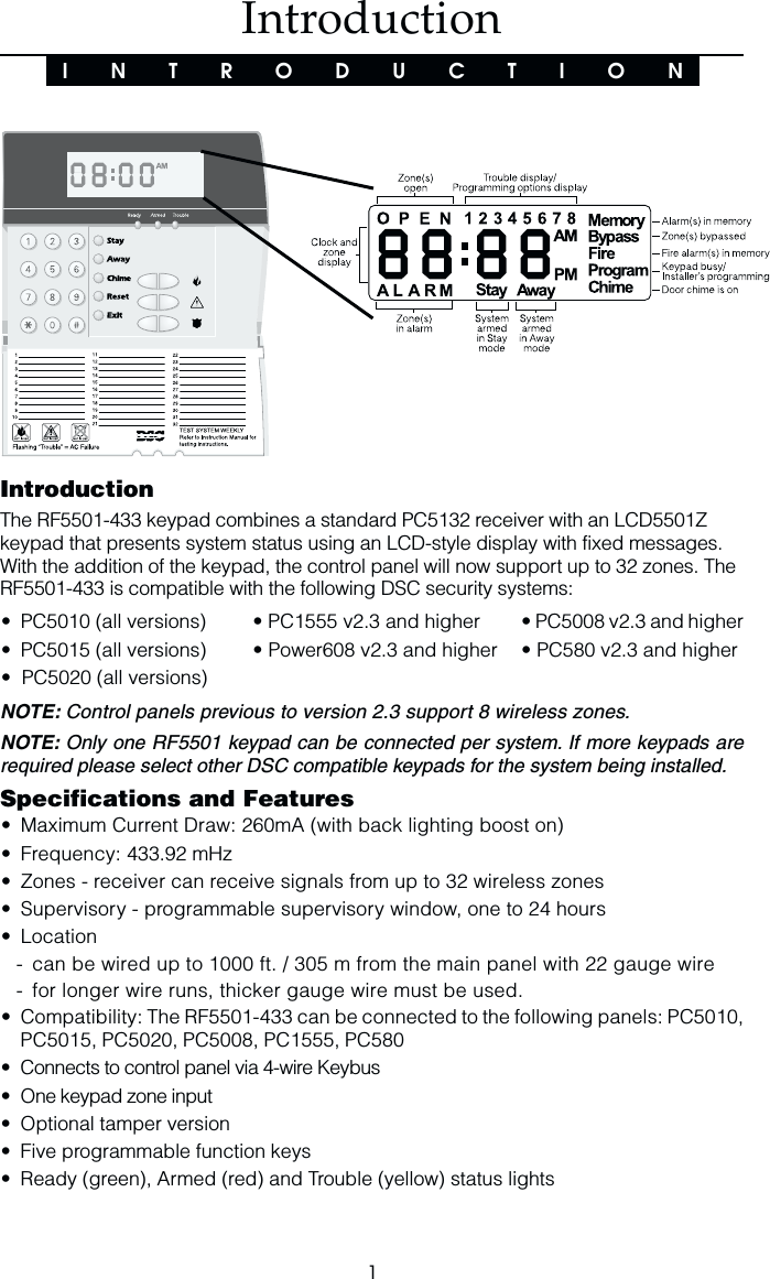
![21.1 UnpackingThe RF5501-433 package includes the following parThe RF5501-433 package includes the following parThe RF5501-433 package includes the following parThe RF5501-433 package includes the following parThe RF5501-433 package includes the following parts:ts:ts:ts:ts:• One RF5501-433 keypad• One 5.6K Ohm resistor• Four mounting screws• One keypad inner door label• One set of Fire, Auxiliary and Panic key labels• One LCD5501Z User Sheet• One RF5501-433 Installation Manual1.2 MountingYou should mount the keypad where it is accessible to designated points of entryand exit. Once you have selected a dry and secure location, perform the followingsteps to mount the keypad:1. Remove the keypad backplate by loosening the screw located at the base of theunit.2. Secure the keypad backplate to the wall in the desired location. Use the screwsprovided.3. Before attaching the keypad to its backplate, complete the keypad wiring asdescribed in the next section.1.3 Wiring1. Before beginning to wire the unit, ensure that all power (AC transformer and battery)is disconnected from the control panel.2. Connect the four Keybus wires from the control panel (red, black, yellow, green, P1and P2/Z) to the keypad terminals (R B Y G P1 P2/Z). Consult the diagram below:RF5501-433RBYGP1P2/ZRed Blk Yel Grn P1 P2/Z3. You can connect a device, such as a door contact, to the “Z” terminal of the RF5501-433. This eliminates the need to run wires back to the control panel for the device. Toconnect the zone, run one wire from the device to the Z terminal and the other wire fromthe device to the B (black) terminal. For powered devices, run the red wire to the R(positive) terminal and the black wire to the B (negative) terminal. When using end ofline supervision, connect the zone according to one of the configurations outlined inyour system’s Installation Manual.InstallationS E C T I O N 1NOTE: P2 is also the zone inputterminal when programmed (seesection [90].](https://usermanual.wiki/Tyco-Safety-Canada/02RF5501433/User-Guide-261923-Page-6.png)
![3I N S T A L L A T I O N1.4 Applying PowerOnce all wiring is complete, apply power to the control panel:1. Connect the battery leads to the battery.2. Connect the AC transformer.For more information on control panel power specifications, see the control panelInstallation Manual.NOTE: Do not connect the power until all wiring is complete.1.5 Enrolling the KeypadOnce all wiring is complete, you will need to enter a 2-digit number that tells thesystem the partition and slot assignment of the keypad.If your system has partitions, you will also need to assign the keypad to a partition(1st digit).The slot assignment (2nd digit) tells the panel which keypad slots are occupied. Thepanel can then generate a fault when a keypad supervisory signal is not present.There are eight available slots for keypads. RF5501-433 keypads are alwaysassigned to slot 1 by default. You will need to assign each keypad to its own slot (1to 8).NOTE: The RF5501-433 enrolls as two modules: 1 = keypad section of the RF5501-43317 = receiver section of the RF5501-433Enter the following at each keypad installed on the system:1. Enter Installer Programming by pressing [*][8][Installer’s Code]2. Press [000] for Keypad Programming3. Press [0] for Partition and Slot Assignment4. Enter a two digit number to specify the partition and slot assignment.NOTE: If your system does not have partitions, enter [1] for the first digit.1st digit Enter 0 for Global Keypad, 1-8 for keypad partitionEnter 1 for Partition 1 KeypadEnter 2 for Partition 2 Keypad2nd digit Enter 1 to 8 for Slot Assignment5. Press the [#] key twice to exit programming.6. After assigning all keypads, perform a supervisory reset by entering [*][8][Installer’sCode][902]. The panel will now supervise all assigned keypads and enrolledmodules on the system.To review which modules the control panel is currently supervising:1. Enter [✱][8][Installer’s Code]2. Enter [903] to display all modules. On the RF5501-433 keypad, 11111 and 1111177777 will scroll onthe keypad to indicate that the RF5501-433 is present on the system. 11111 designatesthe keypad section, and 1717171717 is used to show the receiver section is also supervised.If using an LCD5501Z keypad, scroll until the module name appears on the display.3. To exit press [#].](https://usermanual.wiki/Tyco-Safety-Canada/02RF5501433/User-Guide-261923-Page-7.png)
![52.1 Programming the KeypadThere are several programming options available for the RF5501-433 keypad. Theseare described below. Record all your programming choices in the programmingworksheets included in this manual.Programming the RF5501-433 is similar to programming the rest of the system. Whenyou are in the RF5501-433 programming sections, the keypad will display which optionsare turned on along the top of the display. To turn an option on or off, press the numbercorresponding to the option on the number pad. The numbers of the options that arecurrently turned ON will be displayed.For example, if options 1 and 2 are on, the display will look like this:For information on programming the rest of your security system, please refer to yoursystem’s Installation Manual.2.2 Function Key OptionsThe function keys are programmed in sections [1] to [5]. By default, the 5 function keyson the keypad are programmed as Stay Arm (03), Away Arm (04), Chime (06), SensorReset (14) and Quick Exit (16). You can change the function of each key on everykeypad. Please see your system’s Installation Manual for instructions on programmingthe keys, and a complete list of all the function key options available for your system.2.3 Clock OptionsThe RF5501-433 will display the current time after 30 seconds of no key presses. Toset the correct time and date for the system, please refer to your system’s InstructionManual. You can change how the keypad displays the time with the followingoptions. To change the clock options:1. Enter [*][8][Installer Code]2. Enter [000] to go to keypad programming3. Enter section [6] to go to clock options.4. To turn any of the options on or off, press [1], [2], or [3]:NOTE: If the Time does not display on keypad option is selected, make sure that theKeypad displays time when zones are open option is also selected.[1] ON = Time displays on keypadOFF = Time does not display on keypad[2] ON = Clock display is in AM/PM format(e.g. 08:00 AM)OFF = Clock display is in 24-hour format (e.g. 20:00)[3] ON = Keypad does not display time when zones are openOFF = Keypad displays time when zones are open5. When you are finished programming the clock options,press [#] to exit.NOTE: On a PC5020 v3.2 and higher, if a Loss of Clock troubleis present on the system, the display will be as shown:Keypad ProgrammingS E C T I O N 2:](https://usermanual.wiki/Tyco-Safety-Canada/02RF5501433/User-Guide-261923-Page-9.png)
![62.4 Alarms Displayed While Armed OptionYou can disable the display of alarms on the keypad when the system is armed. Thedisplay of alarms is enabled by default. To disable the display of alarms when thesystem is armed, turn off section [6], option [5]:1. Enter [*][8][Installer’s code]2. Enter [000] to go to keypad programming3. To turn the display of alarms on or off, enter section [6].4. Turn option [5] on or off:[5] ON = Alarms not displayed while system is armedOFF = Alarms are always displayed while system is armed5. When you are finished, press [#] to exit.2.5 Emergency (Fire, Auxiliary, Panic) Key OptionsYou can enable or disable the Fire, Auxiliary and Panic keys at each keypad. Thesekeys are enabled by default. Please see your system’s Installation Manual for moreinformation on these keys and their options. To turn any of the emergency keys on oroff on the keypad:1. Enter [*][8][Installer’s code]2. Enter [000] to go to keypad programming3. Enter section [7].4. To turn the emergency key options on or off, press [1], [2], or [3]:[1] ON = Fire key enabledOFF = Fire key disabled[2] ON = Auxiliary key enabledOFF = Auxiliary key disabled[3] ON = Panic key enabledOFF = Panic key disabled5. When you are finished, press [#] to exit.2.6 Door Chime OptionsYou can program the RF5501-433 keypad to sound a tone when any zone isopened or closed. There are two parts to the RF5501-433 door chime program-ming:•Program if the RF5501-433 will chime when zones are opened and/or closed.•Program the type of sound the RF5501-433 will make when an individual zone is openedor closed.For the door chime feature to work, you will also need to turn on the Door Chime attributefor each zone that will trigger the chime. This programming is done in the control panelsoftware. Refer to your control panel’s Installation Manual for more information.Door Chime on Zone Openings/ClosingsYou can program each RF5501-433 keypad to sound a door chime when zones areopened and/or when they are closed. By default, RF5501-433 keypads are programmed tosound door chimes on both zone openings and closings.To change the door chime opening/closing settings, at each RF5501-433 keypad:1. Enter [*][8][Installer’s code]2. Enter [000] to go to keypad programming3. Enter section [6].K E Y P A D P R O G R A M M I N G](https://usermanual.wiki/Tyco-Safety-Canada/02RF5501433/User-Guide-261923-Page-10.png)
![74. To turn the options on or off, press [6] or [7]:[6] ON = Door Chime Enabled for Zone OpeningsOFF = Door Chime Disabled for Zone Openings[7] ON = Door Chime Enabled for Zone ClosingsOFF = Door Chime Disabled for Zone Closings5. When you are finished, press [#] to exit.Door Chime SoundsYou can program the RF5501-433 keypad to make different door chime sounds forindividual zones, or groups of zones. Each RF5501-433 keypad can make any of fourdoor chime sounds for each zone that triggers the door chime:·4 quick beeps (default sound)·‘Bing – Bing’ tone·‘Ding – Dong’ tone·‘Alarm’ toneNOTE: For a zone to be able to trigger the door chime sound, the Door Chime zoneattribute must also be enabled in the control panel programming. Please see your controlpanel Installation Manual.To change the door chime sounds:1. Enter [*][8][Installer Code].2. Enter [*] to go to door chime sound programming.3. Enter a 2-digit number for the zone you want to program [01] - [32].4. Turn one of the following options on by pressing [1], [2], [3], or [4]:[1] 4 quick beeps (default sound)[2] ‘Bing – Bing’ tone[3] ‘Ding – Dong’ tone[4] ‘Alarm’ toneNOTE: Ensure that only one of the above options is turned on. If more than one is on,the keypad will sound the first option that is enabled. If none of the options are selected,the keypad will not make any sound when the zone is opened or closed.5. To program the door chime sound for another zone, repeat steps 3 and 4.6. When you are finished programming the door chime sounds, press [#] to exit.2.7 Low Temperature AlertThe LCD5501Z-433 v5.0 keypad is capable of detecting a low temperatureenvironment. Once enabled and the zone input disabled (see section [90]), thekeypad will report an alarm condition when armed, if the environment becomes lessthan 6o C. Once the temperature is greater than 8o C, the zone will restore.Enter [*][8] [Installer Code]Enter [000]Enter Section [7]Press [8] to enable/disable temperature sensor[8] ON = Low Temperature Alert enabledOFF = Low Temperature Alert disabledK E Y P A D P R O G R A M M I N G](https://usermanual.wiki/Tyco-Safety-Canada/02RF5501433/User-Guide-261923-Page-11.png)
![8 Receiver ProgrammingS E C T I O N 3Enroll & Program DevicesThis section describes how to enroll and program:•wireless devices using zones (WLS904P, WLS906, WLS907, WLS912, WLS914 andWLS925L)•wireless keys (WLS909, WLS919)For more information on these devices, read the instruction sheet included with eachdevice.3.1 A Note about Electronic Serial NumbersAn electronic serial number (ESN) is printed on the back of each wireless device. ESNsare used to enroll the wireless devices with the RF5501-433 keypad.In order to reduce the occurrence of wireless devices with the same serial number, 6-digit serial numbers are now printed on the back of each wireless device.NOTE: 6-digit serial numbers are only supported on the following control panels: PC5010v2.x and higher, PC5015 v2.2, PC5020, PC5008, PC1555 and PC580.The 6-digit serial numbers include hexadecimal digits. For instructions on programming,hexadecimal numbers, see your system Installation Manual, section 4: How to Program.When connecting the RF5501-433 to a PC5010, PC5020 or PC5015 v1.x panel, enter 5-digit serial numbers only.When connecting the RF5501-433 to a PC5010 v2.x, PC5015 v2.x, PC5020, PC5008,PC1555 or PC580 panel follow the instructions below.Old Wireless Device ESNsYou can use older devices on all versions of the RF5501-433 keypad, even though theyonly have a 5-digit ESN. When using older wireless devices:Enter [0] + 5-digit ESN3.2 Enroll Wireless Devices Using ZonesEnroll wireless devices which use zones (universal transmitters, motion detectors,smoke detectors, and panic pendants):1. At a system keypad, enter [✱][8][Installer’s code] to go the installer’s programmingsection.2. Enter programming section [804].3. Enter the 2-digit number corresponding to the zone the device is to occupy ([01] to [32]).NOTE: Hardwired and wireless devices cannot be assigned to the same zone. PC5108zone expander modules occupy zones in 2 groups of 4 (e.g. zones 9-12 and zones 13-16). None of the zones assigned to a PC5108 module may be used for wireless de-vices. For more information on zone assignment, consult your system InstallationManual.4. Enter the device’s ESN. The entry must be six digits. If an older device with a 5-digitESN is being enrolled, add the digit [0] to the beginning of the ESN. (E.g.,ESN=21234, enter 021234)](https://usermanual.wiki/Tyco-Safety-Canada/02RF5501433/User-Guide-261923-Page-12.png)
![95. The device is now enrolled on the system. Record the serial number and the assignedzone number in the programming worksheets in the back of this manual.6. Continue with steps 3 - 5 until you have enrolled all wireless devices.7. To exit press [#].NOTE: The devices will not work properly until you complete zone and partition pro-gramming (see section 4).3.3 A Note about Electronic Serial NumbersAn electronic serial number (ESN) is printed on the back of each wireless key. ESNs areused to enroll the wireless keys with the PC5102-433 receiver.In order to reduce the occurrence of wireless keys with the same serial number, 6-digitserial numbers are now printed on the back of each wireless key. The 6-digit serial numbersinclude hexadecimal digits. For instructions on programming hexadecimal numbers, seeyour system Installation Manual, Section 4: How to Program.NOTE: 6-digit serial numbers are only supported on the following control panels: PC5020, P-8+, PC501X v2.0 & higher, P832/DL v2.0 and higher, PC1555(MX), P-6B(MX), PC580 and P-48.The (P)WLS909-433 and (P)WLS919-433 keys have both a 5-digit and a 6-digit serial numberprinted on them. When connecting the PC5102-433 to a PC5010 v1.x or P-832 v1.x panel,enter 5-digit serial numbers only. When connecting the PC5102-433 to a PC5020, P-8+,PC5015 v2.x and higher, P832DL v2.x and higher, PC5010 v2.0 and higher, P832 v2.0 andhigher, PC1555(MX), P-6B(MX), PC580 or P-48 panel enter the 6-digit serial number.3.4 Enroll & Program Wireless KeysFor wireless keys to work on the system, you need to enroll them and then program thefunction buttons, if the default values are not the functions desired. Wireless keys are notassigned to zones and require no zone programming. You can enroll up to 8 wireless keyson the system.Enroll Wireless keys1. At a system keypad, enter [✱][8][Installer’s Code] to go to the installer’sprogramming section.2. Enter programming section [804].3. Enter a 2-digit number [41]-[48] to program the wireless key serial number. Thesenumbers correspond to wireless key numbers 01- 08.4. Enter the key’s ESN. The entry must be six digits. If an older key with a 5-digitESN is being enrolled, add the digit [0] to the beginning of the ESN (e.g.,ESN=61234, enter 061234).5. The key is now enrolled on the system. Record the serial number and the assigned slotnumber in the programming worksheets in the back of this manual.6. Repeat steps 3 - 5 until all wireless keys have been enrolled.7. (((((PC5020/P-8+/PC5020/P-8+/PC5020/P-8+/PC5020/P-8+/PC5020/P-8+/PC501PC501PC501PC501PC501X/P832/P832DL X/P832/P832DL X/P832/P832DL X/P832/P832DL X/P832/P832DL only)only)only)only)only) By default, all wireless keys areassigned to Partition 1. To assign keys to Partition 2, enable the appropriate optionsin programming section [91].NOTENOTENOTENOTENOTE: A wireless key can only be assigned to one partition.8. To exit press [#].E N R O L L & P R O G R A M D E V I C E S](https://usermanual.wiki/Tyco-Safety-Canada/02RF5501433/User-Guide-261923-Page-13.png)
![10Program the (P)WLS909-433 or (P)WLS919-433 FunctionButtons(P)WLS909-433 and (P)WLS919-433 wireless keys have four programmable functionbuttons. Default functions have been assigned, but you may program other functionsif desired. After the functions are programmed, when you press and hold one of thefour buttons for one second, the system will execute the programmed function.For systems using partitions (PC5020/P-8+/PC501X/P832/P832DL only): All wirelesskeys assigned to Partition 1 will have the four functions programmed in section [61]. Allwireless keys assigned to Partition 2-8 will have the four functions programmed in section[62-68]. For example, if function button 1 in Section [61] is programmed for Stay arming, thenpressing the first button on wireless keys assigned to Partition 1 will Stay arm Partition 1.NOTE: Wireless keys will not work when the partition they are assigned to is beingaccessed for zone bypassing or programming.1. At a system keypad, enter [✱][8][Installer’s Code].2. Enter programming section [804].3. Enter programming section [61] to [68] for partitions 1 to 8.4. For each of the 4 function buttons, enter the 2-digit number of the function you wantto select. See the programming worksheets in the back of this manual for a list offunction key options.5. Record your programming choices in the worksheets in the back of the manual.6. To exit press [#].3.5 Identified Wireless KeysReporting by the system of openings/closings by individual wireless keys andcommand output [✱][7] activation by wireless key buttons may be supported oncertain control panels. To do this, the system will reserve access codes 17 – 24 forwireless keys 01-08 respectively. You must program one access code for eachwireless key (using [✱][5] access code programming) for this feature to work correctly.NOTE: Program these access codes on the system after you have connected thePC5102-433 to the Keybus (see section 2.4).Refer to your system Installation Manual for information on access code programming.Opening/Closing By Wireless Key ReportingNOTE: The Identified Wireless Key Closing option is only available with the PC5020,P-8+, PC501X v2.0 and higher, P832/DL v2.0 and higher, PC1555(MX), P-6B(MX),PC580 v2.0 and higher, P-48 v2.0 and higher by turning section [015] option 4 off.To enable the reporting of openings and closings by identified wireless keys:•Make sure the control panel is v2.0 or higher•Program a valid access code for each key•Program a closing and opening reporting code for each key’s access code•Turn off the Quick Arm option in section [015] option [4] of the control panelprogrammingE N R O L L & P R O G R A M D E V I C E S](https://usermanual.wiki/Tyco-Safety-Canada/02RF5501433/User-Guide-261923-Page-14.png)
![11E N R O L L & P R O G R A M D E V I C E STo ensure that an unidentified wireless key cannot disarm the system, turn off section[017], option [1] (in the control panel programming). This option is available in controlpanels with software version 2.1 or higher.3.6 PC5102 PGM OutputsThe PC5102-433 has two on-board Form C relay PGM outputs. Each of these can beindividually programmed to:1. Follow main panel PGM outputs 1 to 14.NOTE: Please refer to your System Installation Manual for available PGM outputs.NOTE: If the PC5102-433 is connected to the PC580/PC1555/P-48/P-6B (all versions),PC5010 v1.x, P832 v1.x or the WSS5010 1.0, 2.1, the PC5102 PGM outputs cannot beprogrammed to follow main panel PGM outputs 1 or 2.2. Activate for a programmable amount of time when a signal is received from a wirelesskey programmed with output option 31 or 32 (PC5102 PGM pulse) and the PGMoutput programming section [92] or [93] is programmed with option 15 (PC5102PGM pulse). The amount of time that the PGM outputs can be programmed toremain on is programmed in sections [94] and/or [95]. The default activation time is5 seconds.3. Toggle state when a signal is received from a wireless key programmed with option31 or 32 and the PGM output programming section [92] or [93] is programmed withoption 16 (PC5102 PGM toggle).3.7 Deleting Wireless DevicesTo remove a wireless device from the system, follow the guideline for adding a wirelessdevice. Program the ESN as [000000]. The wireless device for the zone will be removed.NOTE: You may need to remove power from the panel in order to clear troubles causedby deleted zones.Now that you have enrolled all the wireless devices, you will need to program the systemto work properly with the devices. See section 4 for more information.](https://usermanual.wiki/Tyco-Safety-Canada/02RF5501433/User-Guide-261923-Page-15.png)
![124.1 Program Zones and PartitionsNow that you have enrolled the wireless devices, you should complete all zoneprogramming on the system. Although the exact programming required varies de-pending on which control panel the RF5501-433 is connected to, you should check thatthe following programming areas are completed correctly for each wireless zone:•Enable zones and/or assign zones to one or more partitions (programming sections[201]-[209]).•Program the definition for each zone (programming sections [001]-[004]).NOTE: WLS906 wireless smoke detectors must be assigned to zones defined as Delay24-hr fire (wireless) [87] or Standard 24-hr fire (wireless) [88] for proper supervision.•Enable the wireless zone attribute for each wireless zone (PC580, PC1555, PC5008,PC5010 v2.0 and higher, PC5020, PC5015 v2.2 and higher only) (programmingsections [101]-[132]).See your system Installation Manual, for more information on each of the aboveprogramming sections.4.2 Enable Receiver SupervisionThe control panel will automatically supervise the receiver via the Keybus one-minuteafter at least one device has been enrolled on the module. The system will generatea General System Supervisory trouble if the module is removed from the Keybus. If youneed to remove the RF5501-433 from an existing system, you will have to disablesupervision of the PC5132.4.3 Enable Supervision of Wireless ZonesNOTE(for PC5010 v1.x control panels only): For UL Listed installation, Double EOLresistors must be enabled in the PC5010 for the wireless zones to be supervised. Ifnormally Closed or Single EOL resistors are selected the PC5010 will not be able tosupervise the wireless devices. If a wireless device stops sending a supervisory sig-nal (the unit stops functioning) the panel will not indicate a supervisory trouble condi-tion unless Double EOL resistors are used. In addition, all hardwire zones must bewired for Double EOL resistors. For more information, refer to your PC5010 v1.x In-stallation Manual.NOTE (PC5010 v2.0 and higher, PC5015 v2.2 and higher, PC5020, PC5008, PC1555,PC580 only): For wireless supervision to work, you must enable the wireless zone at-tribute on all wireless zones (sections [101] to [132], option [8] ON).NOTE: The RF Jam Detect zone must have the supervision option disabled.Wireless Supervisory WindowEach wireless zone (WLS904P, WLS906, WLS907, WLS912, WLS914, WLS925L) will senda supervisory signal every 64 minutes. If the receiver does not receive a signal within the timeprogrammed for the Wireless Supervisory Window, it will generate a supervisory fault.S E C T I O N 4Other Programming](https://usermanual.wiki/Tyco-Safety-Canada/02RF5501433/User-Guide-261923-Page-16.png)
![13To program the wireless supervisory window:1. Enter [✱][8][Installer Code] to enter Installer Programming.2. Enter [804] to enter into Receiver Programming.3. Enter sections [81].4. Enter the time period for the supervisory window (8 to 24 hours).5. To exit press [#].Disable/Enable Zone SupervisionAll wireless zones have supervision enabled by default. To disable supervision for anyzone, enter the following at any system keypad:1. Enter [✱][8][Installer Code] to enter Installer Programming.2. Enter [804] to enter the PC5132 Module Programming.3. Enter sections [82], [83], [84] and [85]. Disable or enable supervision for eachwireless zone by turning each relevant option on or off.4. To exit press [#].4.4 RF Jam Detect ZoneFor RF jamming detection to work, you must select an unused zone to be used as theRF Jam Detect zone. When the receiver detects an attempt to jam the RF signal, theRF Jam Detect zone will be violated and the system will generate a tamper signal. Whenthe jamming signal is gone, the RF Jam Detect zone closes and the system sends atamper restore signal.To enable RF jamming detection:1. Enter [✱][8] [Installer’s Code].2. Enter programming section [804].3. Enter section [93]. Enter the 2-digit number of the RF Jam Detect zone ([01] to[32]) in the programming section.4. Disable supervision for the RF Jam detect zone by turning the relevant option off insection [82], [83], [84] or [85]. (See section 4.3 for more information.)5. RF jamming detection is now enabled. To exit Installer programming, press [#].4.5 Receiver Software DefaultReturning the receiver programming to factory default settings is a quick way toremove all the enrolled devices from the system and reset all the programming insection [804].NOTE: Performing this procedure will not change any programming sections except[804]. Resetting the control panel to factory default settings will not return the PC5132to factory default settings.To restore the PC5132 programming to the factory default settings, perform thefollowing:1. Enter [✱][8] [Installer’s Code].O T H E R P R O G R A M M I N G](https://usermanual.wiki/Tyco-Safety-Canada/02RF5501433/User-Guide-261923-Page-17.png)
![14O T H E R P R O G R A M M I N G2. Enter programming section [996].3. Enter the Installer’s Code, followed by [996] again. Press [#]. The software for thereceiver section will be restored to its factory default settings.4. Press [#] to exit Installer Programming. After a software default, you must exit andthen re-enter Installer Programming before attempting to program the receiversection.For instructions on restoring the default programming of the control panel or any otherconnected module, see your system Installation Manual.O T H E R P R O G R A M M I N G](https://usermanual.wiki/Tyco-Safety-Canada/02RF5501433/User-Guide-261923-Page-18.png)
![15S E C T I O N 5Testing & Mounting5.1 Test the placement of the WLS904P, WLS906,WLS907, WLS912, WLS914 and the WLS925LIt is very important to test the proposed placement of each wireless device before it ismounted. Following these steps will test the placement of the wireless motion detectors(WLS904P/WLS914), wireless smoke detectors (WLS906), wireless glassbreak detectors(WLS912) and wireless door/window contacts (WLS907/WLS925L), based on the signalstrength between the RF5501-433 and the device.NOTE: You cannot test the Wireless Keys (WLS909/WLS919) in this mode. Seesection 5.2 for instructions on testing these devices. You cannot run a placement teston the RF Jam Detect zone.1. Temporarily place the device you want to test in the place you want to mount it.2. At a system keypad, enter [✱][8][Installer Code].3. Enter programming section [904].4 Enter the 2-digit zone number for the device to be tested.5. Activate the device being tested until a result is displayed on the keypad or soundedby the keypad or bell.WLS904P & WLS914: Remove the detector from its backplate, wait for 1-2 seconds,then reattach the detector to its backplate.WLS906: Remove the detector from its backplate, wait for 5 seconds, then reattachthe detector to its backplate. Or hold a magnet near the raised line on the outer rim.Then remove the magnet.WLS907 & WLS925L: Open and close the contact by moving the magnet awayfrom the unit. If the unit is attached to a door or a window, open and close the dooror window to activate the device.WLS912: Press and hold the test mode tab for 5 seconds. Release the test modetab. The keypad will display the test result.6. Read the test results at the keypad:Result LED Keypad LCD Keypad Buzzer/BellGood Light 1 On Steady “Good”1 Beep/SquawkFair Light 2 On Steady “Fair”2 Beeps/SquawksBad Light 3 On Steady “Bad”3 Beeps/SquawksActivate the device until you get 3 good or fair results in a row. Wait 10 seconds betweeneach test on the same device.You may mount wireless devices where results were good or fair.Devices indicating a bad result must be moved to another location. You may only haveto move the device a few inches to correct a bad result.NOTE: Do not mount any device where a “bad” test result was indicated.If several wireless devices produce BAD test results, you may need to move theRF5501-433 to a better location.7. To test another device, press [#] once, then repeat steps 4 - 6. Continue to test thedevices until both the RF5501-433 and the devices are in good locations.8. To exit installer programming, press [#] twice.](https://usermanual.wiki/Tyco-Safety-Canada/02RF5501433/User-Guide-261923-Page-19.png)
![17S E C T I O N 6Additional Notes6.1 Trouble ConditionsThe control panel always watches for possible trouble conditions. If a trouble conditionoccurs, the keypad “Trouble” light will turn on and the keypad will beep. Press [✱][2]to display the trouble conditions.The following trouble conditions apply to the receiver portion (identified as thePC5132 by the panel) and/or any enrolled devices. For a description of all troubles,please see your system Installation Manual.•General System Tamper•General System Supervisory•Zone Fault•Device Low Battery•Zone TamperWireless Zone Low Battery TransmissionWithin the supervisory transmission, the device will indicate the status of the battery.If a battery is low, the system will indicate a Device Low Battery trouble.The system will delay reporting the event to the central station for the number of daysprogrammed for Zone Low Battery Transmission Delay in section [370]. This willprevent unnecessary reporting of the event if the user has been instructed on how toreplace batteries.6.2 Replacing Batteries in Wireless Devices1 Remove the cover of the device from its backplate. This creates a tamper conditionon the zone.2 Refer to the battery installation instructions on the Installation Sheet of eachcomponent. Be sure to note the proper orientation of the batteries as you installthem.3 When the fresh batteries are in place, re-attach the cover to the backplate. The tamperis restored and the zone sends a battery trouble restoral signal to the receiver. Thebattery trouble is now clear and the device should function normally.NOTE: When batteries in one device need to be replaced, the batteries in all devicesshould be replaced at the same time.](https://usermanual.wiki/Tyco-Safety-Canada/02RF5501433/User-Guide-261923-Page-21.png)
![18S E C T I O N 7Troubleshooting1. When I enter the 2-digit zone number when adding a wireless device, thekeypad gives me a long beep.You cannot enter ESNs unless the RF5501-433 is properly connected to the Keybus. Seesections 1 & 3 for instructions on setting up and wiring the PC5132 module.2. I have entered the ESN for the device but when I violate the device, the zonedoes not show open on the keypad.Check the following:•Ensure the ESN has been entered correctly•Ensure that the zone is enabled for the partition (if partition programming is used).•Ensure that the wireless zone is not assigned to a zone used by PC5108 modules.•Ensure that the zone is programmed for something other than “Null Operation.” Wirelesssmoke detectors must be assigned to zones defined as type [87] or [88].3. When I try a module placement test I get no result or “Bad” results.Check the following (see sections 5.1 and 5.2 for more information on testing devices):•Verify that you are testing the correct zone•Verify that the correct ESN was entered when the device was enrolled•Verify that the device is in range of the RF5501-433. Try testing the device in thesame room as the receiver.•Confirm that the RF5501-433 is properly connected to the Keybus.•Check that you are testing the zone correctly.•Check that the batteries are working and installed correctly.•Look for large metal objects that may be preventing the signal from reaching theRF5501-433.The device must be located where consistent “Good” results are obtained. If severaldevices show “Bad” results, or if panic pendants and wireless keys operate inconsist-ently, move the receiver.4. The LED on the motion detector does not turn on when I walk in front of theunit.The LED is for walk test purposes only. See your WLS904P Instruction Sheet for walktest instructions.](https://usermanual.wiki/Tyco-Safety-Canada/02RF5501433/User-Guide-261923-Page-22.png)
![19S E C T I O N 8Programming Worksheets[000] Keypad Programming1. Enter [*][8][Installer’s code]2. Enter [000] to go to keypad programming[0] Keypad EnrollmentValid entries are 01-18; e.g. enter [11] for partition 1, slot 1. Default = 111st digit Enter 0 for Global KeypadEnter 1 for Partition 1 KeypadEnter 2 for Partition 2 Keypad2nd digit Enter 1 to 8 for Slot AssignmentSlotSlotSlotSlotSlot: I________I________I[1]-[5] Function Key Assignments[1] Key 1 [2] Key 2 [3] Key 3 [4] Key 4 [5] Key 5Defaults: 03 04 06 14 16Stay Away Chime Reset ExitI________I________I I________I________I I________I________I I________I________I I________I________I[6] RF5501-433 Keypad OptionsDefault Option On OffON I________I 1 Local Clock Display Enabled Display DisabledON I________I 2 Local Clock Displays AM/PM Displays 24-hour TimeOFF I________I 3 Open Zones Override Clock Display Do Not Override ClockOFF I________I 4 For Future UseOFF I________I 5 Alarms Not Displayed While Armed Always Displayed While ArmedOFF I________I 6 Door Chime Enabled for Zone Openings Door Chime DisabledOFF I________I 7 Door Chime Enabled for Zone Closings Door Chime DisabledOFF I________I 8 For Future Use[7] Emergency Key OptionsDefault Option On OffON I________I 1 [F] Key Enabled [F] Key DisabledON I________I 2 [A] Key Enabled [A] Key DisabledON I________I 3 [P] Key Enabled [P] Key DisabledOFF I________I 4-7 For Future UseOFF I________I 8 Low Temperature Alert Enabled Low Temperature Alert Disabled](https://usermanual.wiki/Tyco-Safety-Canada/02RF5501433/User-Guide-261923-Page-23.png)
![20[*] Door Chime Sound Programming1. Enter [*][8][Installer’s code][*]2. Enter 2-digit zone number [01] - [32], then select door chime sound option [1] - [4].Repeat for each zone that is to sound a chime.Zone Location [1] [2] [3] [4]4 Beeps “Bing-bing”“Ding-dong”Alarm tone(default)[01] I__________________________________________________________________I I________I I________I I________I I________I[02] II__________________________________________________________________I I________I I________I I________I I________I[03] I__________________________________________________________________I I________I I________I I________I I________I[04] I__________________________________________________________________I I________I I________I I________I I________I[05] I__________________________________________________________________I I________I I________I I________I I________I[06] I__________________________________________________________________I I________I I________I I________I I________I[07] I__________________________________________________________________I I________I I________I I________I I________I[08] I__________________________________________________________________I I________I I________I I________I I________I[09] I__________________________________________________________________I I________I I________I I________I I________I[10] I__________________________________________________________________I I________I I________I I________I I________I[11] I__________________________________________________________________I I________I I________I I________I I________I[12] I__________________________________________________________________I I________I I________I I________I I________I[13] I__________________________________________________________________I I________I I________I I________I I________I[14] I__________________________________________________________________I I________I I________I I________I I________I[15] I__________________________________________________________________I I________I I________I I________I I________I[16] I__________________________________________________________________I I________I I________I I________I I________I[17] I__________________________________________________________________I I________I I________I I________I I________I[18] I__________________________________________________________________I I________I I________I I________I I________I[19] I__________________________________________________________________I I________I I________I I________I I________I[20] I__________________________________________________________________I I________I I________I I________I I________I[21] I__________________________________________________________________I I________I I________I I________I I________I[22] I__________________________________________________________________I I________I I________I I________I I________I[23] I__________________________________________________________________I I________I I________I I________I I________I[24] I__________________________________________________________________I I________I I________I I________I I________I[25] I__________________________________________________________________I I________I I________I I________I I________I[26] I__________________________________________________________________I I________I I________I I________I I________I[27] I__________________________________________________________________I I________I I________I I________I I________I[28] I__________________________________________________________________I I________I I________I I________I I________I[29] I__________________________________________________________________I I________I I________I I________I I________I[30] I__________________________________________________________________I I________I I________I I________I I________I[31] I__________________________________________________________________I I________I I________I I________I I________I[32] I__________________________________________________________________I I________I I________I I________I I________IP R O G R A M M I N G W O R K S H E E T S](https://usermanual.wiki/Tyco-Safety-Canada/02RF5501433/User-Guide-261923-Page-24.png)
![21[804] Wireless Expansion Programming•6-digit entry is required. See Section 3.1 “A note on Electronic Serial Numbers”for details on programming 6-digit serial numbers.•When enrolling devices with 5-digit serial numbers on the RF5501-433, the first digitmust be zero (0), followed by the 5-digit serial number (6-digits total). For example,to enter the serial number 42345 on a RF5501-433, enter “042345.”Zone Serial NumbersDefault = 000000[01] Zone 1 l_____l_____l_____l_____l_____l_____l[02] Zone 2 l_____l_____l_____l_____l_____l_____l[03] Zone 3 l_____l_____l_____l_____l_____l_____l[04] Zone 4 l_____l_____l_____l_____l_____l_____l[05] Zone 5 l_____l_____l_____l_____l_____l_____l[06] Zone 6 l_____l_____l_____l_____l_____l_____l[07] Zone 7 l_____l_____l_____l_____l_____l_____l[08] Zone 8 l_____l_____l_____l_____l_____l_____l[09] Zone 9 l_____l_____l_____l_____l_____l_____l[10] Zone 10 l_____l_____l_____l_____l_____l_____l[11] Zone 11 l_____l_____l_____l_____l_____l_____l[12] Zone 12 l_____l_____l_____l_____l_____l_____l[13] Zone 13 l_____l_____l_____l_____l_____l_____l[14] Zone 14 l_____l_____l_____l_____l_____l_____l[15] Zone 15 l_____l_____l_____l_____l_____l_____l[16] Zone 16 l_____l_____l_____l_____l_____l_____l[17] Zone 17 l_____l_____l_____l_____l_____l_____l[18] Zone 18 l_____l_____l_____l_____l_____l_____l[19] Zone 19 l_____l_____l_____l_____l_____l_____l[20] Zone 20 l_____l_____l_____l_____l_____l_____l[21] Zone 21 l_____l_____l_____l_____l_____l_____l[22] Zone 22 l_____l_____l_____l_____l_____l_____l[23] Zone 23 l_____l_____l_____l_____l_____l_____l[24] Zone 24 l_____l_____l_____l_____l_____l_____l[25] Zone 25 l_____l_____l_____l_____l_____l_____l[26] Zone 26 l_____l_____l_____l_____l_____l_____l[27] Zone 27 l_____l_____l_____l_____l_____l_____l[28] Zone 28 l_____l_____l_____l_____l_____l_____l[29] Zone 29 l_____l_____l_____l_____l_____l_____l[30] Zone 30 l_____l_____l_____l_____l_____l_____l[31] Zone 31 l_____l_____l_____l_____l_____l_____l[32] Zone 32 l_____l_____l_____l_____l_____l_____lP R O G R A M M I N G W O R K S H E E T S](https://usermanual.wiki/Tyco-Safety-Canada/02RF5501433/User-Guide-261923-Page-25.png)
![22P R O G R A M M I N G W O R K S H E E T SWireless Key Serial NumbersDefault = 000000[41] Key 01 l_____l_____l_____l_____l_____l_____l[42] Key 02 l_____l_____l_____l_____l_____l_____l[43] Key 03 l_____l_____l_____l_____l_____l_____l[44] Key 04 l_____l_____l_____l_____l_____l_____l[45] Key 05 l_____l_____l_____l_____l_____l_____l[46] Key 05 l_____l_____l_____l_____l_____l_____l[47] Key 07 l_____l_____l_____l_____l_____l_____l[48] Key 08 l_____l_____l_____l_____l_____l_____l[49] Key 09 l_____l_____l_____l_____l_____l_____l[50] Key 10 l_____l_____l_____l_____l_____l_____l[51] Key 11 l_____l_____l_____l_____l_____l_____l[52] Key 12 l_____l_____l_____l_____l_____l_____l[53] Key 13 l_____l_____l_____l_____l_____l_____l[54] Key 14 l_____l_____l_____l_____l_____l_____l[55] Key 15 l_____l_____l_____l_____l_____l_____l[56] Key 16 l_____l_____l_____l_____l_____l_____l Wireless Key Function Key OptionsEntry Key Description Entry Key Description00 Null Key 16 [✱][0] Quick Exit01-02 For Future Use 17 [✱][1] Reactivate Stay/Aways03 Stay Arm 18 For Future Use04 Away Arm *19 [✱][7][3] Command Output #305 [✱][9] No-Entry Arm 20 For Future Use06 [✱][4] Chime ON/OFF *21 [✱][7][4] Command Output #407 [✱][6][——][4] System Test 22-26 For Future Use08-12 For Future Use 27 Disarm (OFF)*13 [✱][7][1] Command Output #1 28 Fire Alarm*14 [✱][7][2] Command Output #2 /Sensor Reset29 Auxiliary Alarm15 For Future Use 30 Panic Alarm*Sensor Reset can be used when the RF5501-433 is connected to the PC5010.Command outputs are not available for PC5010 software v1.x.](https://usermanual.wiki/Tyco-Safety-Canada/02RF5501433/User-Guide-261923-Page-26.png)
![23P R O G R A M M I N G W O R K S H E E T SWireless Key OptionsPartition 1 Wireless Key Options[61] Function Key 1 03 l____l____lFunction Key 3 27 l____l____lFunction Key 2 04 l____l____lFunction Key 4 30 l____l____lPartition 2 Wireless Key Options[62] Function Key 1 03 l____l____lFunction Key 3 27 l____l____lFunction Key 2 04 l____l____lFunction Key 4 30 l____l____lPartition 3 Wireless Key Options[63] Function Key 1 03 l____l____lFunction Key 3 27 l____l____lFunction Key 2 04 l____l____lFunction Key 4 30 l____l____lPartition 4 Wireless Key Options[64] Function Key 1 03 l____l____lFunction Key 3 27 l____l____lFunction Key 2 04 l____l____lFunction Key 4 30 l____l____lPartition 5 Wireless Key Options[65] Function Key 1 03 l____l____lFunction Key 3 27 l____l____lFunction Key 2 04 l____l____lFunction Key 4 30 l____l____lPartition 6 Wireless Key Options[66] Function Key 1 03 l____l____lFunction Key 3 27 l____l____lFunction Key 2 04 l____l____lFunction Key 4 30 l____l____lPartition 7 Wireless Key Options[67] Function Key 1 03 l____l____lFunction Key 3 27 l____l____lFunction Key 2 04 l____l____lFunction Key 4 30 l____l____lPartition 8 Wireless Key Options[68] Function Key 1 03 l____l____lFunction Key 3 27 l____l____lFunction Key 2 04 l____l____lFunction Key 4 30 l____l____lSupervision[81] Wireless supervisory WindowDefault = 32l____l____l wireless device window (x15min), valid entries are 32-96.[82] Zone Device Supervision Options (1-8)Zone Device Supervision Options (1-8)Zone Device Supervision Options (1-8)Zone Device Supervision Options (1-8)Zone Device Supervision Options (1-8)Default = ON Option ON Option OFFl________lOption 1 Zone 01 Supervision enabled Disabledl________lOption 2 Zone 02 Supervision enabled Disabledl________lOption 3 Zone 03 Supervision enabled Disabledl________lOption 4 Zone 04 Supervision enabled Disabledl________lOption 5 Zone 05 Supervision enabled Disabledl________lOption 6 Zone 06 Supervision enabled Disabledl________lOption 7 Zone 07 Supervision enabled Disabledl________lOption 8 Zone 08 Supervision enabled Disabled](https://usermanual.wiki/Tyco-Safety-Canada/02RF5501433/User-Guide-261923-Page-27.png)
![24P R O G R A M M I N G W O R K S H E E T S[84] Zone Device Supervision Options (17-24)Default = ON Option ON Option OFFl________lOption 1 Zone 17 Supervision enabled Disabledl________lOption 2 Zone 18 Supervision enabled Disabledl________lOption 3 Zone 19 Supervision enabled Disabledl________lOption 4 Zone 20 Supervision enabled Disabledl________lOption 5 Zone 21 Supervision enabled Disabledl________lOption 6 Zone 22 Supervision enabled Disabledl________lOption 7 Zone 23 Supervision enabled Disabledl________lOption 8 Zone 24 Supervision enabled Disabled[85] Zone Device Supervision Options (25-32)Default = ON Option ON Option OFFl________lOption 1 Zone 25 Supervision enabled Disabledl________lOption 2 Zone 26 Supervision enabled Disabledl________lOption 3 Zone 27 Supervision enabled Disabledl________lOption 4 Zone 28 Supervision enabled Disabledl________lOption 5 Zone 29 Supervision enabled Disabledl________lOption 6 Zone 30 Supervision enabled Disabledl________lOption 7 Zone 31 Supervision enabled Disabledl________lOption 8 Zone 32 Supervision enabled Disabled[91] Wireless Keys (1-8) Partition AssignmentsDefault = 01Default = 01Default = 01Default = 01Default = 01Wireless Key 01 l____l____lWireless Key 02 l____l____lWireless Key 03 l____l____lWireless Key 04 l____l____lWireless Key 05 l____l____lWireless Key 06 l____l____lWireless Key 07 l____l____lWireless Key 08 l____l____l](https://usermanual.wiki/Tyco-Safety-Canada/02RF5501433/User-Guide-261923-Page-28.png)
![25P R O G R A M M I N G W O R K S H E E T S[92] PC5102 PGM1 Output OptionDefault 01Default 01Default 01Default 01Default 01PGM1 Output Option l________l ________l[93] PC5102 PGM2 Output OptionDefault 02Default 02Default 02Default 02Default 02PGM2 Output Option l________l ________l[94] PC5102 - PGM1 Output Activation TimeDefault 00Default 00Default 00Default 00Default 00PGM1 Output Activation Time (Minutes) l________l ________lDefault 05Default 05Default 05Default 05Default 05PGM1 Output Activation Time (Seconds) l________l ________l[95] PC5102 - PGM2 Output Activation TimeDefault 00Default 00Default 00Default 00Default 00PGM2 Output Activation Time (Minutes) l________l ________lDefault 05Default 05Default 05Default 05Default 05PGM2 Output Activation Time (Seconds) l________l ________lNOTE: Sections [94] and [95] have a valid minimum programmable value of 00 minutes01 seconds, and a valid maximum programmable value of 99 minutes 99 seconds.RF Jamming Detection[96] RF Jam Detect ZoneRF Jam Detect ZoneRF Jam Detect ZoneRF Jam Detect ZoneRF Jam Detect ZoneDefault = 00Default = 00Default = 00Default = 00Default = 00l____l____lSelect an unused zone that will be violated when a jammingsignal is detected. (Valid entries = 01 - 32, 00 = RF Jam detectdisabled.)](https://usermanual.wiki/Tyco-Safety-Canada/02RF5501433/User-Guide-261923-Page-29.png)