Tyco Safety Canada 06GS30552 Cellular Alarm Communicator User Manual 29007314R001 GS3055 IM EN P65
Digital Security Controls Ltd. Cellular Alarm Communicator 29007314R001 GS3055 IM EN P65
User manual
GSM-GPRS INTERFACE

2 GS3055-I
INTRODUCTION ....................................................................................................................3
FEATURES ............................................................................................................................ 3
Technical Specifications ....................................................................................................... 3
Description ............................................................................................................................ 4
IDENTIFICATION OF PARTS ............................................................................................... 4
INSTALLING THE DEVICE ................................................................................................... 4
CONNECTING THE DEVICE ................................................................................................ 4
STATUS LEDS ....................................................................................................................... 5
OPERATING PRINCIPLES ................................................................................................... 5
Simulated Land Line .............................................................................................................5
SMS Function ........................................................................................................................ 6
ContactID Mode .................................................................................................................... 6
Function Priority ..................................................................................................................... 6
Simulated Land Line Priority ....................................................................................... 6
SMS or Contact ID Priority ........................................................................................... 6
ContactID Event Priority .............................................................................................. 6
ACTIVATING THE OUTPUTS ................................................................................................ 7
Activating/Deactivating Automatic Outputs ......................................................................... 7
Activating/Deactivating Remote-control Outputs ................................................................ 7
Bistable Outputs (for appliance management) ........................................................ 7
Monostable Outputs (for appliance management) .................................................. 7
PROGRAMMING THE SIM CARD VIA PC ........................................................................... 8
Viewing the Device Settings ...................................................................................... 8
Downloading the Device Settings ............................................................................. 8
Preliminary operations ................................................................................................ 8
Telephone Page .................................................................................................................... 8
Telephone Numbers .................................................................................................... 8
Prefix ............................................................................................................................ 9
Digit to Remove ........................................................................................................... 9
SMS Dialler Page ................................................................................................................... 9
Main window ............................................................................................................... 9
Priority ....................................................................................................................... 10
Pay-as-you-go balance message ........................................................................... 10
Periodic message .................................................................................................... 10
Outputs Page ...................................................................................................................... 10
Output Settings ........................................................................................................ 10
Access Code ........................................................................................................... 10
Contact ID Page .................................................................................................................. 10
Telephone numbers to call ....................................................................................... 11
Events description ..................................................................................................... 11
Send over GPRS ........................................................................................................ 11
Periodic Reports ........................................................................................................ 11
GPRS page .......................................................................................................................... 11
Access Point Name ................................................................................................... 11
Receiver IP address and Port ................................................................................... 11
APNs User Name and Password ............................................................................... 11
Telephone numbers to decode ................................................................................ 11
SIM number ............................................................................................................... 11
DNIS ........................................................................................................................... 11
Account code ........................................................................................................... 11
Calls Page ............................................................................................................................ 11
Load button ............................................................................................................... 12
Received Calls .......................................................................................................... 12
Missed Calls ............................................................................................................... 12
Dialled Calls ............................................................................................................... 12
Status Page ......................................................................................................................... 12
Status section ............................................................................................................ 12
Inputs section ............................................................................................................ 12
Outputs section ......................................................................................................... 12
Events section ........................................................................................................... 12
Clear call queue ........................................................................................................ 12
"C-24 REMOTE" PROGRAMMING ..................................................................................... 1 3
INFORMATION FOR THE USER ......................................................................................... 13
Remote Programming of the Access Code ....................................................................... 13
GSM Network Calls .............................................................................................................. 13
Further Information .............................................................................................................. 13
APPENDIX .......................................................................................................................... 14
3
INTRODUCTION
,,
,,
,
This manual provides programming and operating instructions for the GS3055-I wireless alarm
communicators. Information relating to a specific model will be denoted by the applicable model number
within the text. The term "Device" is used to describe functionality that is applicable to both models. This
manual shall be used in conjunction with the installation manual of the control panel and power supply it
is connected to.
FEATURES
Simulates land line
Switches automatically to GSM Network in the event land line trouble (line down)
Manages and signals Incoming/Outgoing calls
GSM signal indicator
4 programmable OC Outputs
Houses 12V - 1.2 Ah battery (not included)
Tamper protection
Land line overvoltage protection (optional)
Dual-Band
4 Input Lines
SMS Alerts
Contact ID Dialer throughout
Decoding Contact ID protocol from a PSTN interface for communication over the GPRS network
GPRS/Internet communication with Sur-Gard System III / II
13 SMS Messages (2 messages per Input Line and 5 Status messages)
8 phone numbers (max. 20 digits) programmable for SMS Dialler
4 phone numbers programmable for Contact ID Dialler
Up to 95 phone numbers (max. 20 digits) can be programmed to manage remote control of the OC Outputs
Remote control of the OC Outputs via SMS and/or over-the-phone after caller recognition
Pay-As-You-Go Balance message (for pre-paid SIM Cards)
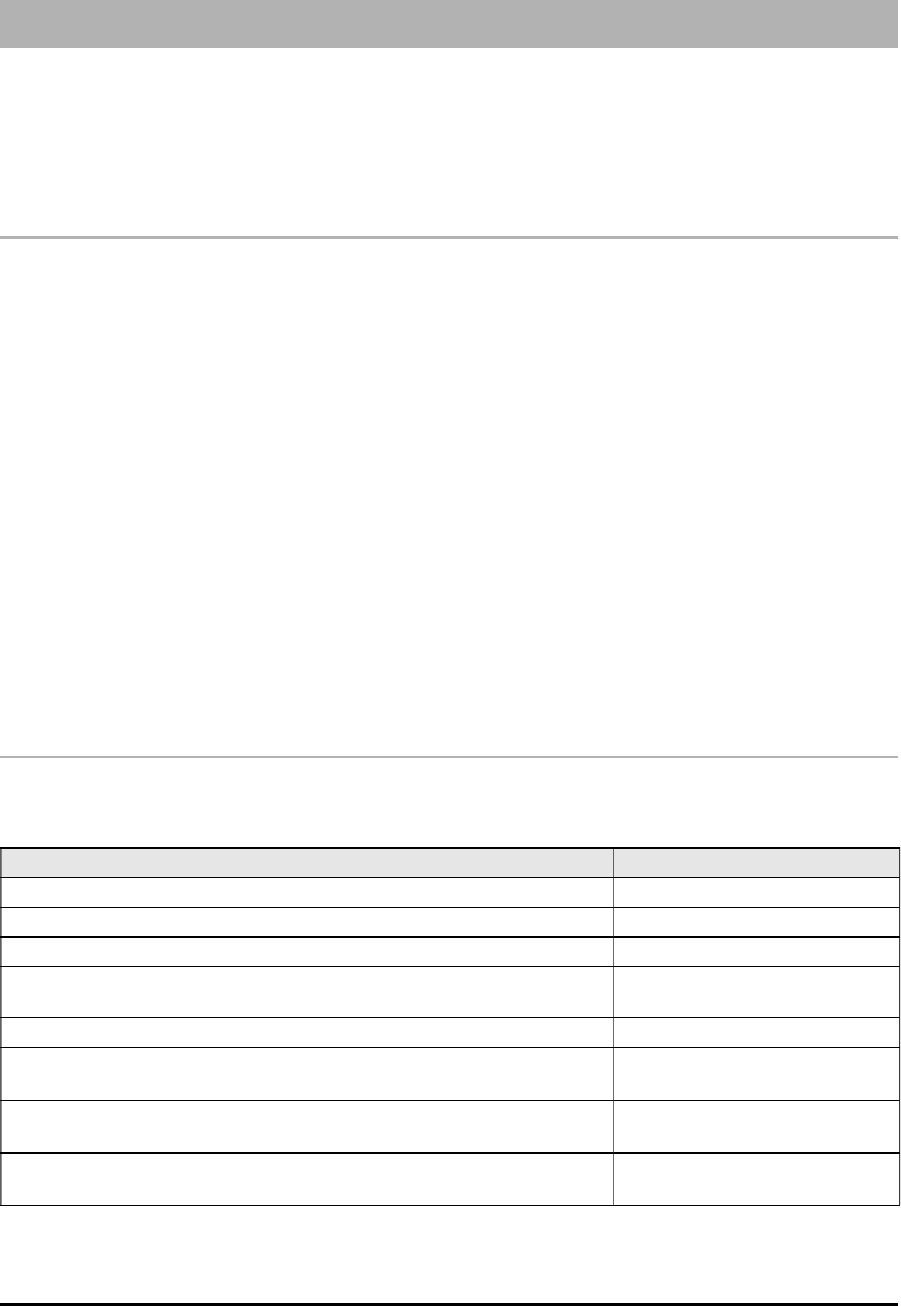
Technical Specifications
The 13.8 V_ (700 mA max.) power supply voltage to this Device can be drawn from the Control panel or provided by a
ADP1512 AC/DC adapter (accessory item) or provided by the PS4085 power supply.
Description Value
Power Supply voltage 13.8 V_
Standby Current Draw 100 mA
Transmitting Current Draw 700 mA
Maximum loop resistance of line between the series device
and the CPE connected to the device 1 Kohm
Maximum number of parallel CPE devices 2
Operating Temperature +0° to +49° C
32 to 120 °F
Dimensions 138 x 224 x 55 mm
5.4 x 8.8 x 2.2 inch
Weight (without battery) 900 g
3.2 oz.

4 GS3055-I
Description
This Device provides total confidence in all security and surveillance applications. It manages SMS and Central Station
transmissions and can simulate the land line in the event of trouble (land line down) or even substitute the land line completely
in areas where the GSM service is provided and where the land line is not available.
This Device supports CONTACTID, 10 bps and 20 bps protocols and, in places with optimum GSM signal reception, SIA and
CESA protocols.
The GS3055-I has the added capability of communicating alarm signals via the GPRS data network. The capability enables
a fast reliable path to central stations equipped with a Sur-Gard System III, System II receiver, or with the PC based WinBCS
software (version 2.0 or higher).
By connecting a GS3055-I to a control panel's standard PSTN interface, telephone based Contact ID signals are decoded and
seamlessly routed through the GPRS network to any of the compatible receiver options.
The performance of this Device depends greatly on GSM Network coverage, therefore, it should not be mounted without first
performing placement tests to determine the best location (best reception). This Device has 4 Input lines which can be used to
activate SMS and/or Contact ID transmissions (Trouble alert, Periodic messages or Pay-As-You-Go Balance (for pre-paid SIM
Cards).
This Device has 4 Outputs which can be set up from remote locations or used for status signalling.
Due to the characteristics of GSM Networks, this Device can activate only as intended and cannot be used as a modem for
fax/data transmissions or for teleservice operations.
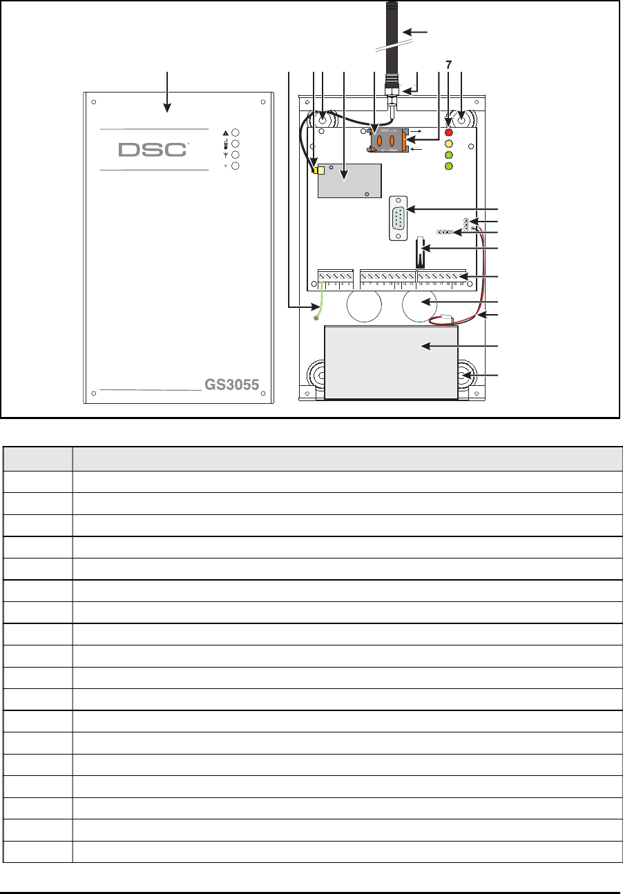
IDENTIFICATION OF PARTS
The numbers in square brackets [ ] in this manual refer to the main parts of the GS3055-I (see Fig. 1) described in this section.
INSTALLING THE DEVICE
This device shall be installed by qualified SERVICE PERSONS only. This device must be installed indoors in a non-
hazardous location. This Device should be located in a dry place away from radio transmitters and similar devices.
,,
,,
,
Test the GSM Network reception before mounting this Device in the proposed placement.
1. Remove the 4 screws and the metal casing [1].
2. Using the back box, mark the 4 screw locations then drill the anchor screw holes.
Check for cable conduits and water pipes before drilling.
3. Using anchor screws (not included), mount the back box to the wall.
4. Lay the cables, then pull them through the cable entry [14].
5. Fit the antenna [2] (ensure that the bolt [3] is fastened tightly).
6. Using the connector [5], connect the GSM Module [17].
7. Following the arrow on the board, insert the SIM-CARD [6] face down in the SIM holder (see Figure 1).
The SIM-CARD PIN must be disabled.
8. Complete the connections on the terminal board [12].
9. Using the 4 scews and washers, reattach the frontplate [1] securely to the back box.
,,
,,
,
Connect power and TNV circuit only after the cabinet has been secured to the building or structure and has
been connected to the protective earth ground.
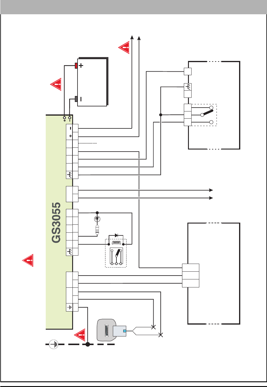
CONNECTING THE DEVICE
This section describes the various terminals. Fig. 2 shows a typical wiring diagram.
(1) Earth: This terminal must be connected to the Mains Earth, in order to comply with the Telecommunications Network
Safety Standards (Overvoltage Protection Requirements).
LE (2-3) External telephone line: These terminals can be connected to the land line.
LI (4-5) Internal telephone line: These terminals (normally connected to the land line) must be connected to the telephone
device terminals (for example, terminals L.E.).
(6-14) Negative: Power Supply.

5
Ox (7-8-9-10) Programmable Open-Collector Outputs: These outputs can be activated either by programmed events
(Automatic Mode) or by SMS text messages (Remote Mode), refer to “Activating the Outputs” for details. The maximum
current draw of each OC Output must not exceed 70 mA
+OC
(2-3) Common terminal for Open-Collector Outputs: Common power-supply terminal (12 Vcc-450mA) for all OC
Outputs (O1, O2, O3, O4).
AS (12-13) Tamper: These terminals are connected in series to the Tamper microswitch [11]. They will be closed when the
Device is properly closed, and will open when the frontplate is removed.
Lx (15-16-17-18) Programmable Input line: These terminals can be set up to activate the SMS and Contact ID transmission
functions.
12V
(19-20) Device power supply: These terminals must be connected to a 13.8 V_ power supply, 700 mA minimum —
under normal circumtances drawn from a Control panel or ADP1512 Adaptor (accessory item). If the Device power
supply is drawn from a Control panel, ensure that the maximum current draw (700 mA) is protected by a
resettable fuse or similar device.
Once the connections have been completed, connect the Red and Black wires [13] to a 12V-1, 2Ah battery.
,,
,,
,
To ensure proper operation of this Device, the connection of a backup battery is needed to provide
temporary additional current during normal operation (see Fig. 2)
,,
,,
,
This Device must be connected to a 13.8 V power supply and to a backup battery. This device must be
connected to a proper Earth Ground (see Fig. 2).
,,
,,
,
When disposing of batteries, follow the instructions and and precautions printed on the batteries, and
contact your municipal offices for information on the disposal of used batteries.
STATUS LEDS
The Device Interface has 4 status LEDs.
,,
,,
,
All 4 LEDs will blink during the Initializing and Programming phases.
The following section describes the Control panel status LEDs.
GREEN — If this LED is OFF and the RED LED is ON, the GSM Network service is unavailable (NO SERVICE).
This LED will Blink when the GSM Network reception is bad, if this occurs, only SMS transmissions will be possible.
If this LED is ON (glowing), the GS3050-I and GS3055-I Interface will be able to manage all telephone communications.
GREEN — When this LED is ON (glowing), the reception is good. This LED will switch ON only when the other GREEN
LED is ON (glowing).
AMBER — This LED will switch ON (glowing) when the interface switches to the GSM Network (due to land line trouble).
This LED will Blink in the event of an incoming or outgoing call (regardless of the operating status of the land line).
RED — This LED is Normally OFF, it will blink in the event of power trouble. This LED will switch ON (glowing) in the
event of GSM Module [17] trouble, or when the GSM Network is unavailable (NO SERVICE), or when Remote
Programming option is enabled. If this LED switches ON (glowing), and the two Green LEDs indicate the availability of
the GSM Network service, ONLY Emergency calls will be possible.
OPERATING PRINCIPLES
Simulated Land Line
The Simulated land line provides traditional telephone devices with a backup line in the event of land line trouble (line down). This
operating mode will allow calls and data transmissions to be carried on the land line. If the voltage on the land line terminals (LE)
drops below 3 V for a period of between 10 to 45 seconds (depending on the device connected to the LI terminals), the Device
will switch the connected telephone device to the GSM Network for a full 15 minute interval, at the end of this interval, it will
check the land line:
— if the land line has been restored, it will switch the connected telehone device back to the land line;
— if the land line is still down, it will continue to simulate the land line until remove it is fully restored.

6 GS3055-I
This Device will not switch during ongoing calls. The simulated line will provide the line ring voltage for incoming calls and
will decode DTMF dialling (this Device is unable to decode Pulse dialling).
The Function Priority (to be selected during the programming phase) will determine how this Device manages communications
(SMS and ContactID) and calls from the telephone device connected to the LI terminals (e.g. Control panel).
SMS function
This operating mode allows this Device to send text messages to 8 telephone numbers. The messages can be associated
with the following events:
Alarm signals on the 4 Programmable Input lines: 2 preset messages — Alarm and End of Alarm.
Land Line Test: 2 preset messages — Line down and Line restored.
Power supply Test: 2 preset messages — Trouble and Trouble clear
Periodic message: 1 message to be sent at regular intervals (accepted values 1 through 999999 minutes).
,,
,,
,
The SMS messages will be sent to the programmed numbers when the respective events occur.
ContactID Mode
This operating mode will allow this Device to send calls to the Central Station:
Alarm signals on the 4 Programmable Input lines: require Event Codes and Customer Codes
Status signal, with a Customer Code
Land Line Test:
Power supply Test:
Call queue full
Periodic report (to be sent at regular intervals — accepted values 1 through 999999 minutes).
,,
,,
,
The Contact ID reports will be sent when the respective events occur.
Function Priority
Simulated Land Line Priority
If the equipment connected to the LI terminals (e.g. Control panel) tries to engage the line, this Device will interrupt any
ongoing communications (SMS or ContactID) in order to send the calls generated by the device. This Device will restart the
interrupted communications when the equipment disengages the line.
SMS or Contact ID Priority
If the equipment connected to the LI terminals (e.g. Control panel) is using the GSM Network (through this Device) when an
SMS or ContactID associated event occurs, this Device will interrupt the ongoing call and send the respective SMS message
or ContactID report.
ContactID Event Priority
If several events occur contemporarily, the respective messages will be sent in chronological order. If an event is associated
with a ContactID report and an SMS communication, priority will be given to the ContactID report.

7
ACTIVATING THE OUTPUTS
This Device has 4 OC outputs programmable as Automatic (outputs with this attribute will activate in response to the
associated events) or Remote Control (outputs with this attribute can be activated manually from remote locations by
means of SMS messages or calls from enabled telephone numbers.
Activating/Deactivating Automatic Outputs
The OC outputs can be activated automatically by the following events:
Land line trouble (line down)
GSM Module trouble
GSM trouble (Limited/No Service)
Power supply trouble
Incoming call
Outgoing call
ContactID digital report
Enablement of remote programming
,,
,,
,
Once an OC output has been activated automatically, it will not restore to standby until all the causes of
activation clear.
Activating/Deactivating Remote-control Outputs
The OC outputs can be programmed as BISTABLE (activated/deactivated by means of an SMS text message or Remote
Control number) or MONOSTABLE (activated by means of SMS text messages or Remote Control numbers). Once
a Monostable output has been activated, it will not deactivate until the programmed ON Time expires. Each output can be
set up to provide a feedback signal (ring or SMS text message).
,,
,,
,
For further information regarding the terms “Access Code” and “Output Label” (used in the following
section), refer to the “Outputs Page” in the “Software” section.
Bistable Outputs (for appliance management)
Bistable OC outputs can be activated in 2 ways.
1. By sending a case sensitive SMS text message containing the respective Access Code, placed between pound signs
(#), and the Output Label (e.g. GATE) followed by =ON, as follows:
#ACCESSCODE#OUTPUTLABEL=ON (example: #AZ55#GATE=ON)
2. By sending a cost-free call from a preset Remote Control number. This Device will activate the respective output
without answering the call.
,,
,,
,
Bistable OC outputs can be deactivated by sending a case sensitive SMS text message containing the respective
Access Code placed between pound (#) signs and Output Label (e.g. GATE) followed by =OFF, as follows:
#ACCESSCODE#OUTPUTLABEL=OFF (example: #AZ55#GATE=OFF)
The SIM-CARD can be programmed via PC, using the GS3050 Software Application or via any GSM Cellphone or in "C-24
Monostable Outputs (for appliance management)
Monostable OC outputs can be activated in 2 ways.
1. By sending a case sensitive SMS text message containing the respective Access Code placed between pound (#) signs
and Output Label followed by “=ON” or “=OFF”, as follows:
#ACCESSCODE#OUTPUTLABEL=ON
#ACCESSCODE#OUTPUTLABEL=OFF
2. By sending a cost-free call from a preset Remote Control number. This Device will activate the output concerned
without answering the call.
,,
,,
,
Monostable OC outputs deactivate (switch OFF) automatically when the programmed ON Time expires
Programming the Device
,,
,,
,
If this Device is to manage all the SMS functions, use a 32 K SIM CARD (or higher) which holds at least 20
text messages.

8 GS3055-I
The SIM-CARD can be programmed via PC, using any GSM cellphone or in “C-24 Remote” mode, with pre-authorized service.
NOTE: The manufacturer shall not assume responsibility for damage arising from improper programming via
GSM Cellphone.
Fig. 3 - Null-Modem cable connection for programming via PC
PROGRAMMING THE SIM CARD VIA PC
This section contains the programming instructions using the GS3055 Software Application. This programming method
requires the connection of a Null-Modem cable (see Fig. 3) to the RS232 input [10] of this Device and the computer COM port.
Once the Null-Modem cable has been connected, set the computer COM port through the Settings->Serial Port option from
the Menu.
Viewing the Device Settings
To view the Device settings on the screen, use the Programming->Load option from the Menu.
Downloading the Device Settings
Once programming has been completed (or an uploaded file containing existing data has been modified), download the data
into this Device, using the Programming->Download option from the Menu.
Preliminary operations
When the application starts, you will be presented with the Main window showing two sections on the left hand side.
zFolders: This section will allow you to click on the various Programming and Control Pages.
zCustomers: This section will allow you to delete or retrieve configuration data, as follows:
1. Using the right button on the mouse, click on the Customer’s name.
2. Click Load to upload the respective data from the Hard-Disk, or Delete to delete the data configuration.
You can load the configuration data by double clicking the respective name field.
You can list Customers in alphabetical or code order by clicking the heading of the column concerned.
,,
,,
,
To start the configuration of a new Customer, click on File->New Customer then select the device (GS3055-I) from the
product list in the successive window.
The configuration data is presented on 4 pages, a further 2 pages (Calls and Status) are for “Supervisory and Control”
purposes. All the pages are described in detail in this section.
Telephone Page
The Telephone Page phonebook holds 95 telephone numbers.
,,
,,
,
The first eight numbers in the phonebook will also be used for the SMS functions.
Telephone Numbers
Description: enter an alphanumeric string of up to 20 characters.
Number: enter a telephone number of up to 20 digits (only digits and “+” signs are accepted).
Remote Control Numbers: select the telephone numbers which will be able to control Outputs 1, 2, 3 and 4 over the
phone. The telephone numbers cannot be selected in open order, therefore, if telephone numbers 1 and 6 are selected,
telephone numbers 2, 3, 4 and 5 will be selected automatically.
5 5
4 4
9 9
8 8
7 7
6 6
3 3
2 2
1 1
DB9 female connector
7 wire shielded cable
DB9 female connector
to PCto this Device
9
Dial.: This memorandum column shows the SMS Dialler telephone numbers (selected on the SMS Dialler Page from
the first 8 telephone numbers in the phonebook).
Prefix
IMPORTANT: This Device will prefix the digits entered in this field to all the telephone numbers dialled through the GSM
Interface function.
If necessary enter a Prefix (maximum 4 digits) in this field. If no Prefix is required, leave this field empty.
Digit to Remove
If this Device is connected downstream to a switchboard, the telephone numbers (programmed on the Control panel) must
be preceded by the switchboard number (normally one digit). As the switchboard number is not required when calls are sent
over the GSM Network, it must be removed from the digits which form the telephone number. Enter the number of digits that
form the switchboard number (e.g. if switchboard number is 01, enter 2 in the ‘Digits to remove’ field, as 2 numbers form the
switchboard number).
SMS Dialler Page
This page will allow you to program the SMS Dialler functions and Messages and also set up the ‘Special Functions’ of the
3 Input lines.
,,
,,
,
The configuration data on on this page concerns the first eight telephone numbers entered on the “Telephone”
page.
Main window
The column on the left-hand side of the Main window shows the events which, if duly programmed, will generate two SMS
text messages: one for activation and the other for restoral (the ‘Periodic SMS text message can generate the activation
message only).
Polarity: (this column shows the events which unbalance the 4 Input lines), select the Standby polarity of the Inputs
— H-Normally Open or L-Normally Closed.
Telephone Numbers: click (tick) the check boxes of the numbers to be called when the respective event occurs.
SMS: write the Activation and/or Restoral message to be sent when the respective event occurs (maximum 100
characters). If no message is required, leave the respective box empty.
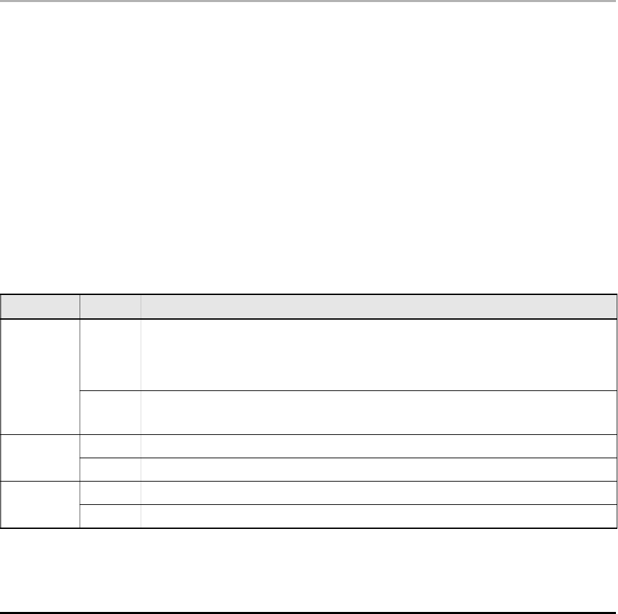
Serv: If this option is enabled, unbalance (on Input Lines 1, 2 and 3) will generate actions instead of calls. Two actions
can be set up for each Input Line, as per the following table.
Input line no. Select Special Functions
1
A
Enable/Disable Periodic Message
If this option is selected — and Input Line 1 is held in a permanent state of Unbalancet his device will
send the Periodic Message at regular intervals (in accordance with the values in the
Periodic Message section). If Input Line 1 restores to standby status (Input Line 1 balance this device will not
send the Periodic Message
B
Send Periodic Message now
If this option is selected this device will send the Periodic Message immediately and start the interval
between messages
2AClear Call Queue
BRestore Reserved Outputs to Standby
3ASwitch to GSM
BAlternative Dialling

10 GS3055-I
Priority
This section will allow you to select the operating priority of this Device: Interface (at default) or SMS Dialler/Contact ID
Communicator.
Pay-as-you-go Balance message
,,
,,
,
NOTE: The Manufacturer shall not assume responsibility for Pay-as-you-go credit services managed by
GSM Network Providers.
If you enable this option, an SMS text message — containing information provided by the GSM Network regarding the end-user’s
credit balance — will be sent to the first number in the Telephone Number list. Enter the number of telephone calls
(ContactID reports and/or outgoing SMS text messages) this Device must allow before checking the Pay-as-you-go balance.
Pay-As-You-Go Balance message - If you click on this button the application will open a window showing the remaining credit
balance (if this service is managed by your network provider), or a message indicating that this service is not available.
The default string in the 'Pay-As-You-Go Balance message' field (*123#) is supported by most major service providers.
Periodic message
This section will allow you to set up the Periodic message options.
Date of first Periodic message - Select the Date of the first Periodic message.
Time of the first Periodic message - Select the Time of the first Periodic message.
Interval - Enter the interval (DD-HH-MM) between each Periodic message. Accepted DAY values: 0 to 693.
,,
,,
,
ATTENTION: If Input Line 1 is assigned to Special functions (Column A), transmission of the Periodic
message will be subordinate to ‘Unbalance’ on Input Line 1 (refer to the ‘Special functions’ table). If this
occurs, the Date and Hour of the Periodic message will be irrelevant.
Outputs Page
This page will allow you to set up and control the outputs.
Output Settings
Polarity: select the polarity of the output: H-Normally Open L-Normally Closed.
For Land Line Trouble, GSM Trouble, etc.: select the events that will activate the outputs.
Reserved Output: If this option is selected, all other events assigned to the output in this section will be ignored. Select
this option, if the output concerned is to be used for Remote control purposes (refer to “Activating and Deactivating and
Remote Control Outputs”).
The following options will affect Reserved Outputs ONLY.
Output Label - Type in the label (max. 8 characters) of the appliance (e.g. Gate) which is to be remote-controlled
via SMS.
Output feedback - Select the type of feedback signal (None, Ring or SMS) to be sent when the respective output
activates. If the Output Label field is empty, the SMS option will not be available.
Monostab. - Under normal circumstances, these outputs hold active status until they receive a deactivation
command. If automatic deactivation is required, it will be necessary to program the ON Time (i.e. the time the output
will hold active status).
ON Time (sec.) - Enter the required ON Time in seconds (accepted values 2 to 254 seconds). If the output has been
programmed as Monostable, this value will determine the amount of time the output will hold active status before
restoring to standby.
Access Code
Type in the code (maximum 4 alphanumeric characters) which will allow the user to control the outputs over-the-phone.
Contact ID Page
This page will allow you to set up the Contact ID function.

11
Telephone numbers to call
Four telephone numbers of up to 20 digits (digits and + signs).
This Device will try each telephone number 3 times before considering a call unsuccessful and quitting.
,,
,,
,
The Contact ID Codes will be sent to the first number (with Contact ID reporting protocol) that answers the
call.
Events description
Customer Code - type in a 4 character code (accepted values: digits and the letters A, B, C, D, E and F).
Event Code - type in the Contact ID to be transmitted when the respective event occurs.
Send - select (tick) the events to be sent.
Send over GPRS
If this option is enabled, the GS3055-I will only communicate Contact ID events via the GPRS network.
Periodic Reports
This Device can be programmed to send Periodic Contact ID reports. This section will allow you to select the Date and Time
of the first periodic report and the Interval between reports.
GPRS Page
This page outlines the GPRS configuration options.
Access Point Name
Enter the Access Point Name of the GPRS service provider being used. (example: ibox.tim.it) Please contact the GPRS
service provider for this information.
Receiver IP address and Port
Enter the receiver IP address and the port number. Use the same as IP address and Port that is found in the 'Receiver Remote
Port' section of the WinBCS software or Sur-Gard SYSTEM III and SYSTEM II.
APNs User Name and Password
Some providers may require a user name and password to validate communication. If needed, enter this information here.
Telephone numbers to decode
In this section you may enter up to two telephone numbers dialed by the panel that will be recognized by the GS3055-I when
called to trigger GPRS communication. If a number is programmed, any time a number dialed does not match one of the
phone number entered, the call will be routed through the voice channel. Leaving it blank will route all calls to GPRS.
SIM number
Enter the GPRS SIM number (optional)
DNIS
If required, enter the Dialled Number Identification Service number.
Account code
An account code is required for communication with WinBCS, Sur-Gard SYSTEM III or SYSTEM II receivers. Enter the
Account Code in this field.
Calls Page
This page will allow you to view on the screen the Dialled, Received and Missed calls.
,,
,,
,
Each section can store a maximum of 10 calls. If the number of calls exceeds this limit, this Device will make
space automatically by deleting the oldest calls.

12 GS3055-I
Load button
To view the Dialled, Received and Missed calls, click the Load button. Depending on programming, some telephone
numbers may not have Caller ID.
Received Calls
If this Device is connected to a Control panel or another telephone device, this section will allow you to view the calls
received by this Device.
Missed Calls
This section will allow you to view any unanswered incoming calls.
Dialled Calls
This section will allow you to view any calls dialled by this Device whether in Contact ID Communicator mode and/or GSM
Interface mode.
Status Page
This page will allow you to monitor and control in real-time all the Device functions and, if not previously done, unblock the
SIM CARD PIN.
,,
,,
,
ATTENTION: This page is updated every 5 seconds.
Status section
This section shows the GSM Module data. This virtual display shows the GSM Network Provider, the Device battery charge
(for the precise level, position the mouse arrow on the battery icon for a several seconds) and GSM signal reception
(indicated by 10 bars).
The virtual Comunication LED is usually GREEN. It will turn RED in the event of a breakdown in communication between
the software and this Device. If it turns AMBER, this Device is either reading the SIM CARD or receiving/making a telephone
call, under these circumstances the status update will be suspended temporarily.
Inputs section
This section shows the status of each of the 4 Inputs (GREEN LED = Input balanced; RED LED = Input Unbalanced) and any
Special functions associated with the Inputs.
Outputs section
This section shows the status of each of the 4 Outputs (GREEN LED = Output in standby; RED LED = Output activated). If
any of the Outputs has been set up as “Reserved” (refer to “Outputs page”), RED LED On, it will be possible to activate/
deactivate the Outputs in real-time by right-clicking the respective Polarity option and selecting the Activate/Deactivate sub-
option.
Events section
This section shows the events as they occur (RED LED On).
Send next periodic message on
This section shows the Date and Time of the next periodic SMS text message (refer to the SMS dialler page).
Send next periodic report on
This section shows the Date and Time of the next periodic Contact ID report (refer to the Contact ID Communicator page).
Clear call queue
This button will allow you to interrupt any ongoing calls and stop the outgoing call queue.
,,
,,
,
This option is available ONLY when this Device operates in SMS Dialler/Contact ID Communicator mode.

13
"C-24 REMOTE" PROGRAMMING
The GS3055-I can be remotely programmed via SMS by Connect-24 (C-24) for fast convenient installation without the need
of an on-site PC or manual programming of the SIM card.
INFORMATION FOR THE USER
Remote Programming of the Access Code
To change the Acess Code, use the following SMS text message:
#uuuu#*#nnnn#
where:
uuuu represents the old Access Code, and nnnn represents the new Access Code.
,,
,,
,
The default Access Code is
0001
.
GSM Network Calls
If this Device is connected to a telephone, it will be possible to make calls on the GSM Network.
Further Information
Refer to the following sections for further information:
STATUS LEDs
OPERATING PRINCIPLES
ACTIVATING THE OUTPUTS
“Remote Programming” in the “PROGRAMMING VIA PC section”
14 GS3055
Fig. 2 - Wiring Diagram
5
41
Panel
Telephone device
236
789
10 11 14 15 16 17 18 19 20
LE
LI O1O2 O3 O4
+OC
13
12
AS
L1 L2 L3 L4
12V
To Tamper Line
13.8 V A_700 m
Fire Panel / Security Panel
o
1K5
BATTERY
NO NC
COM
+B
This Connection is necessary
O1
Relay
T
I
P
T
I
P
R
I
N
G
R
I
N
G
P
G
M
P
G
M
RJ
45
APPENDIX
15
1
51
96
LE LI
-
O1
M
O2 O3 O4
+OC
AS
M
L1 L2 L3 L4 +12V-
LOCK
OPEN
44
518 3
2
6
17
10
11
8
12
14
13
16
15
4
9
N. Parts
1Metal Casing
2G S M A ntenna
3G S M A ntenna nuts
4Anchor Screw holes (Ø 3 mm)
5Conne ctor for G S M A ntenna
6SIM CARD
7LE Ds
8Reserved Jum per
9Reserved Jum per (Jum per m ust be connected as per Fig. 1)
10 RS -232 Conne cto r
11 F ro n tp la te Ta m p e r S w itc h
12 Term inal B oard
13 B a tte ry C o n n e c to r
14 Cable entry
15 Earth Cable
16 12V-1.2Ah B attery
17 GSM Module
18 SIM holder
Fig. 1 - Parts

FCC COMPLIANCE STATEMENT
CAUTION: Changes or modifications not expressly approved by Digital Security Controls could void your
authority to use this equipment. This equipment generates and uses radio frequency energy and if not
installed and used properly, in strict accordance with the manufacturer's instructions, may cause interference
to radio and television reception. It has been type tested and found to comply with the limits for Class B
device in accordance with the specifications in Subpart "B" of Part 15 of FCC Rules, which are designed to
provide reasonable protection against such interference in any residential installation. However, there is
no guarantee that interference will not occur in a particular installation. If this equipment does cause
interference to television or radio reception, which can be determined by turning the equipment off and
on, the user is encouraged to try to correct the interference by one or more of the following measures:
• Re-orient the receiving antenna
• Relocate the alarm control with respect to the receiver
• Move the alarm control away from the receiver
• Connect the alarm control into a different outlet so that alarm control and receiver are on different
circuits.
If necessary, the user should consult the dealer or an experienced radio/television technician for additional
suggestions. The user may find the following booklet prepared by the FCC helpful: "How to Identify and
Resolve Radio/Television Interference Problems". This booklet is available from the U.S. Government
Printing Office, Washington, D.C. 20402, Stock # 004-000-00345-4.
WARNING: To satisfy FCC RF exposure requirements for mobile transmitting devices, a
separation distance of 20 cm or more must be maintained between the antenna of this device
and persons during device operation.
Industry Canada Compliance Statement
This Class B digital apparatus meets all requirements of the Canadian interference-causing equipment
regulations. Cet appareil numérique de la Classe B respecte toutes les exigences de règlement sur le
matériel brouilleur du Canada.
The term “IC:” before the radio certification number only signifies that Industry Canada technical
specifications were met. This manual is applicable to the following GS3055-I Cellular Alarm
Communicator Models:
GS3055-1 FCC ID: F5306GS30551 and IC: 160A-GS30551
GS3055-2 FCC ID: F5306GS30552 and IC: 160A-GS30552
© 2006 Digital Security Controls
Toronto, Canada
1-800-387-3630 • www.dsc.com
Printed in Canada
29007314R002