Tyco Safety Canada 06PC5132 ASK Receiver User Manual
Digital Security Controls Ltd. ASK Receiver
UserManual.wiki
>
Tyco Safety Canada
>
06PC5132 User Manual
User Manual
Navigation menu
Upload a User Manual
Namespaces
Wiki Guide
HTML
PDF
Info
Views
User Manual
Discussion / Help
Navigation

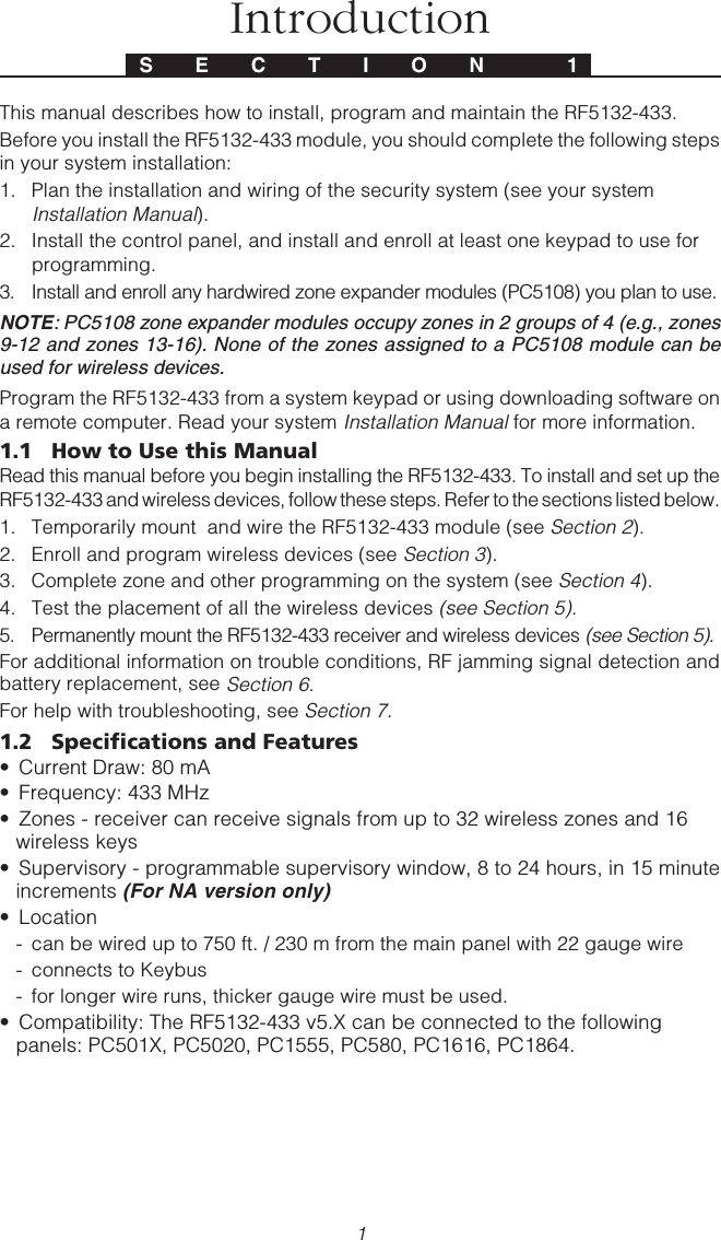
![4Enroll & Program DevicesThis section describes how to enroll and program:• wireless devices using zones (WLS904PL-433, WLS906-433, WS4916,WLS912L-433, WLS914-433, WS4938, WS4955 and WLS925L-433)• wireless keys (WLS919-433, WS4939)For more information on these devices, read the instruction sheet included with eachdevice.3.1 Identified Wireless KeysReporting by the system of openings/closings by individual wireless keys andcommand output [*][7] activation by wireless key buttons may be supported oncertain control panels. To do this, the system will reserve access codes 17 – 32 forwireless keys 01-16 respectively. You must program one access code for eachwireless key (using [*][5] access code programming) for this feature to workcorrectly.NOTE: Program these access codes on the system after you have connected theRF5132-433 to the Keybus (see section 2.4).Refer to your system Installation Manual for information on access code programming.Opening/Closing By Wireless Key ReportingNOTE: The Identified Wireless Key Closing option is only available with the PC5020,PC1616, PC1864, P-8+, PC501X v2.0 and higher, P832/DL v2.0 and higher,PC1555(MX), P-6B(MX), PC580/585 v2.0 and higher, P-48 v2.0 and higher by turn-ing section [015] option 4 off.To enable the reporting of openings and closings by identified wireless keys:• Make sure the control panel is v2.0 or higher• Program a valid access code for each key• Program a closing and opening reporting code for each key’s access code• Turn off the Quick Arm option in section [015] option [4] of the control panelprogrammingTo ensure that an unidentified wireless key cannot disarm the system, turn off section[017], option [1] (in the control panel programming). This option is available in controlpanels with software version 2.1 or higher.3.2 Enroll Wireless Devices Using ZonesEnroll wireless devices which use zones (universal transmitters, motion detectors,smoke detectors, and panic pendants):1. At a system keypad, enter [*][8][Installer’s code] to go the installer’s programmingsection.2. Enter programming section [804].3. Enter the 2-digit number corresponding to the zone the device is to occupy ([01] to[32]).NOTE: Hardwired and wireless devices cannot be assigned to the same zone. PC5108S E C T I O N 3Receiver Programming](https://usermanual.wiki/Tyco-Safety-Canada/06PC5132/User-Guide-627372-Page-6.png)
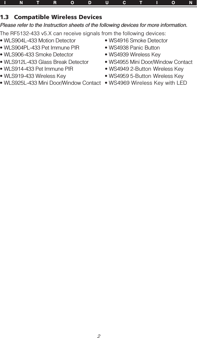
![5zone expander modules occupy zones in 2 groups of 4 (e.g. zones 9-12 and zones13-16). None of the zones assigned to a PC5108 module may be used for wirelessdevices. For more information on zone assignment, consult your system Installa-tion Manual.4. Enter the device ESN. The entry must be 6 digits.5. The device is now enrolled on the system. Record the serial number and theassigned zone number in the programming worksheets in the back of thismanual.6. Continue with steps 3 - 5 until you have enrolled all wireless devices.7. To exit press [#].NOTE: The devices will not work properly until you complete zone and partitionprogramming (see section 4).3.3 A Note about Electronic Serial Numbers (ESN)An electronic serial number (ESN) is printed on the back of each wireless key. ESNsare used to enroll the wireless keys with the RF5132-433 receiver.In order to reduce the occurrence of wireless keys with the same serial number, 6-digit serial numbers are now printed on the back of each wireless key. The 6-digitserial numbers include hexadecimal digits. For instructions on programming hexa-decimal numbers, see your system Installation Manual, Section 4: How to Program.NOTE: 6-digit serial numbers are only supported on the following control panels:PC5020, PC1616, PC1864, P-8+, PC501X v2.0 & higher, P832/DL v2.0 and higher,PC1555(MX), P-6B(MX), PC580/585 and P-48.3.4 Enroll & Program Wireless KeysFor wireless keys to work on the system, you need to enroll them and then programthe function buttons, if the default values are not the functions desired. Wireless keysare not assigned to zones and require no zone programming. You can enroll up to16 wireless keys on the system.Enroll Wireless Keys1. Enter [*][8][Installer’s Code] to go to the installer’s programming section.2. Enter programming section [804].3. Enter a 2-digit number [41]-[56] to program the wireless key serial number.These numbers correspond to wireless key numbers 01- 16.4. Enter the device ESN. The entry must be six digits.5. The key is now enrolled on the system. Record the serial number and theassigned slot number in the programming worksheets in the back of this manual.6. Repeat steps 3 - 5 until all wireless keys have been enrolled.7. (PC5020/PC1616/PC1864/P-8+/PC501X/P832/P832DL only) By default, allwireless keys are assigned to Partition 1. To assign keys to differentpartition, see programming section [69].NOTE: A wireless key can only be assigned to one partition.8. To exit press [#].Programming the Wireless Keys Function Buttons(P)WLS919-433 and WS4939 wireless keys have four programmable functionbuttons. Default functions have been assigned, but you may program other functionsW I R E L E S S D E V I C E S](https://usermanual.wiki/Tyco-Safety-Canada/06PC5132/User-Guide-627372-Page-7.png)
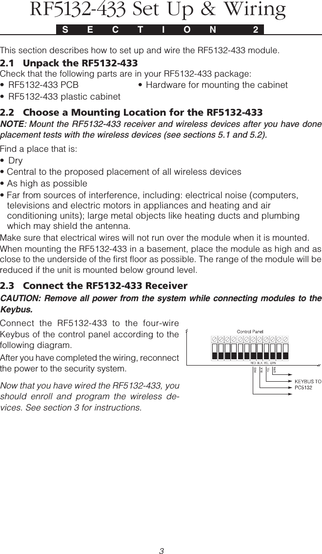
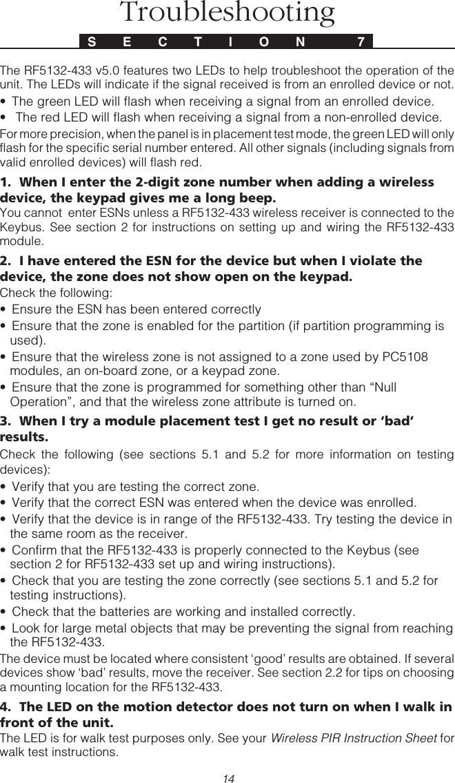
![6if desired. After the functions are programmed, when you press and hold one of thefour buttons for one second, the system will execute the programmed function.For systems using partitions (PC5020/PC1616/PC1864/P-8+/PC501X/P832/P832DLonly): All wireless keys assigned to Partition 1 will have the four functions programmedin section [61]. All wireless keys assigned to Partition 2-8 will have the four functionsprogrammed in section [62-68]. For example, if function button 1 in Section [61] isprogrammed for Stay arming, then pressing the first button on wireless keys assignedto Partition 1 will Stay arm Partition 1.NOTE: Wireless keys will not work when the partition they are assigned to is beingaccessed for zone bypassing or programming.1. At a system keypad, enter [*][8][Installer’s Code].2. Enter programming section [804].3. Enter programming section [61] to [68] for partitions 1 to 8.4. For each of the 4 function buttons, enter the 2-digit number of the functionyou want to select. See the programming worksheets in the back of thismanual for a list of function key options.5. Record your programming choices in the worksheets in the back of the manual.6. To exit press [#].3.5 RF5132-433 LEDsThe RF5132-433 v5.0 features two LEDs to help troubleshoot the operation of theunit. The LEDs will indicate if the signal received is from an enrolled device or not.• The green LED will flash when receiving a signal from an enrolled device.• The red LED will flash when receiving a signal from a non-enrolled device.For more precision, when the panel is in placement test mode, the green LED will onlyflash for the specific serial number entered. All other signals (including signals fromvalid enrolled devices) will flash red.3.6 Deleting Wireless DevicesTo remove a wireless device from the system, follow the guideline for adding awireless device. Program the ESN as [000000]. The wireless device for the zone willbe removed.Now that you have enrolled all the wireless devices, you will need to program thesystem to work properly with the devices. See section 4 for more information.W I R E L E S S D E V I C E S](https://usermanual.wiki/Tyco-Safety-Canada/06PC5132/User-Guide-627372-Page-8.png)
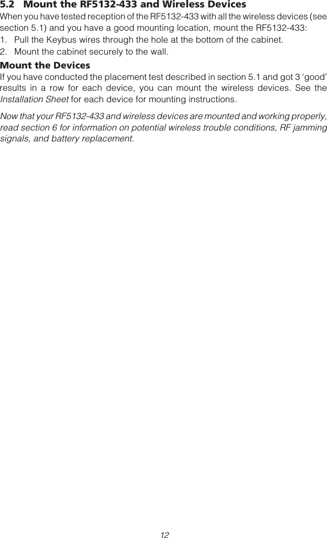
![74.1 Program Zones and PartitionsNow that you have enrolled the wireless devices, you should complete all zoneprogramming on the system. Although the exact programming required variesdepending on which control panel the RF5132-433 is connected to, you shouldcheck that the following programming areas are completed correctly for eachwireless zone:• Enable zones and/or assign zones to one or more partitions (programmingsections [202]-[205] or [202] to [265] for the PC5020/PC1616/PC1864).• Program the definition for each zone (programming sections [001]-[004]).• Enable the wireless zone attribute for each wireless zone (PC580, PC1555,PC1616, PC1864, PC501X v2.0, PC5020 v3.0 and higher only) (sections[101]-[132]).See your system Installation Manual, for more information on each of the aboveprogramming sections.4.2 Enable RF5132-433 SupervisionThe control panel will supervise the RF5132-433 receiver via the Keybus after at leastone device has been enrolled on the module (see section 3.2 “Enrolling WirelessDevices”).To activate module supervision, after you enroll the first device(s):1. Exit and then re-enter installer’s programming2. Enter programming section [902]. Wait approximately 1 minute.3. To exit press [#].The system will generate a General System Supervisory trouble if the module isremoved from the Keybus. If you need to remove the RF5132-433 module from anexisting system, you will have to disable supervision of the RF5132-433.NOTE: Deleting all devices from the RF5132-433 or defaulting the RF5132-433 willcause a supervisory faultTo disable RF5132-433 supervision:1. Disconnect the RF5132-433 from the Keybus2. Enter [*][8][Installer Code]3. Enter [902]. The control panel will clear all supervision and re-scan the system forconnected modules. The scan will take approximately one minute.4. To exit press [#].To review which modules the control panel is currently supervising:1. Enter [*][8][Installer’s Code]2. Enter [903] to display all modules. On LED keypads, light [17] will indicatethat the RF5132-433 is present on the system. On LCD keypads, scroll untilthe module name appears on the display.3. To exit press [#].S E C T I O N 4Other Programming](https://usermanual.wiki/Tyco-Safety-Canada/06PC5132/User-Guide-627372-Page-9.png)
![8If the RF5132-433 module does not show on the keypad, one of the followingconditions may be present:• the module is not connected properly to the Keybus• there is a problem with the Keybus wiring run• the module does not have enough power• no devices have been enrolled on the RF5132-4334.3 Enable Supervision of Wireless ZonesNOTE: (for PC5010 v1.x control panels only) In order for wireless zones to be super-vised, you must enable Double End of Line (DEOL) supervision in the PC5010 con-trol panel. For more information, refer to your Installation Manual.NOTE: (PC5020, PC1616, PC1864, PC501X, PC1555, PC580 v2.0 and higher only)For wireless supervision to work, you must enable the wireless zone attribute on allwireless zones (sections [101] to [132], option [8] ON).Wireless Supervisory WindowEach wireless zone (WLS906-433,WLS904P-433 or WLS925L-433) will send a supervi-sory signal every 64 minutes. If the receiver does not receive a signal within the timeprogrammed for the Wireless Supervisory Window, it will generate a supervisory fault.To program the wireless supervisory window:1. Enter [*][8][Installer Code] to enter Installer Programming.2. Enter [804] to enter the RF5132-433 Module Programming.3. Enter section [81].4. Enter the time period for the supervisory window. The window is programmedin 15 minute increments. The default programming is 96 (x15minutes), whichis equal to 24 hours. Valid entries are (32) - (96), equal to 8 - 24 hours. (ForNA version only.)5. To exit press [#].NOTE: Supervision must be enabled for RF Delinquency.Disable/Enable Zone SupervisionAll wireless zones have supervision enabled by default. To disable supervision forany zone, enter the following at any system keypad:1. Enter [*][8][Installer Code] to enter Installer Programming.2. Enter [804] to enter the RF5132-433 Module Programming.3. Enter sections [82], [83], [84] and [85]. Enable or disable supervision foreach wireless zone by turning each relevant option on or off.4. To exit press [#].4.4 RF Jam Detect ZoneFor RF jamming detection to work, you must select an unused zone to be used as theRF Jam Detect zone. When the receiver detects an attempt to jam the RF signal, theRF Jam Detect zone will be violated and the system will generate a tamper signal.When the jamming signal is gone, the RF Jam Detect zone closes and the systemsends a tamper restore signal.To enable RF jamming detection:1. Enter [*][8] [Installer’s Code].2. Enter programming section [804].O T H E R P R O G R A M M I N G](https://usermanual.wiki/Tyco-Safety-Canada/06PC5132/User-Guide-627372-Page-10.png)
![9O T H E R P R O G R A M M I N G3. Enter section [93]. Enter the 2-digit number of the RF Jam Detect zone ([01]to [32]) in the programming section.4. Disable supervision for the RF Jam detect zone by turning the relevant option off insection [82], [83], [84] or [85]. (See section 4.3 for more information.)5. RF jamming detection is now enabled. To exit Installer programming, press [#].NOTE: For UL Listed installations, the RF Jam feature must be enabled - Section[804], subsection [90], Option [7] OFF.4.5 RF5132-433 Software DefaultReturning the RF5132-433 programming to factory default settings is a quick way toremove all the enrolled devices from the system and reset all the programming insection [804].NOTE: Performing this procedure will not change any programming sections except[804]. Resetting the control panel to factory default settings will not return the RF5132-433 module to factory default settings.To restore the RF5132-433 programming to the factory default settings:1. Enter [*][8] [Installer’s Code].2. Enter programming section [996].3. Enter the Installer’s Code, followed by [996] again. The software for theRF5132-433 will be restored to its factory default settings.4. To continue programming the unit, exit installer’s programming by pressing[#] and then re-enter installer’s programming by entering [*][8] [Installer’sCode].For instructions on restoring the default programming of the control panel or anyother connected module, see your system Installation Manual.4.6 Deleting Wireless DevicesTo remove a wireless device from the system, follow the guideline for enrolling awireless device (see section 3.2). Program the ESN as [000000]. The wireless devicefor the zone will be removed.NOTE: You may need to remove power from the panel in order to clear troublescaused by deleted zones.Now that you have completed all RF5132-433 related programming, you can test andmount the receiver and devices. See section 5 for more information.](https://usermanual.wiki/Tyco-Safety-Canada/06PC5132/User-Guide-627372-Page-11.png)
![10Testing & MountingS E C T I O N 55.1 Test the Reception of Wireless DevicesIt is very important to test the proposed placement of each wireless device before it ismounted. Following these steps will test the signal strength between the RF5132-433and the wireless devices.You can test all of the devices together (global placement testing) or test each deviceindividually. To test all the devices together, see ‘Testing All Wireless DevicesTogether’ below. To test wireless devices individually, see ‘Testing IndividualDevices’. After you have enrolled the wireless devices, you must exit and thenre-enter Installer’s Programming at least once before you can perform aplacement test.Testing All Wireless Devices Together:1. Temporarily put the WLS904P-433, WLS906-433, WLS907-433, WLS912-433,WLS914-433 and WLS925L-433 devices in the places you want to mount them.2. At a system keypad, enter [*][8][Installer Code].3. Enable the Global Module Placement test by entering section [804]. Thenenter sub-section [90] and turn on option [8].4. Press [#] twice.5. Enter programming section [904], then enter [01].6. Activate one of the devices being tested until a result is displayed on thekeypad or sounded by the keypad or bell:WLS904P-433/WLS914-433: To perform a Placement Test on the WLS904P-433, remove the detector from the back plate and then replace it. Once thedetector is replaced on the back plate the LED on the detector will flashrapidly 5 times (4 times for the WLS914-433) to indicate that it has sent atransmission. The panel will show and/or sound the result of the placementtest on the keypad. To perform a 2nd and 3rd test, repeat this procedure.Carefully replace the backplate onto the detector, ensuring that “TOP” isCarefully replace the backplate onto the detector, ensuring that “TOP” isCarefully replace the backplate onto the detector, ensuring that “TOP” isCarefully replace the backplate onto the detector, ensuring that “TOP” isCarefully replace the backplate onto the detector, ensuring that “TOP” isfacing upward, or you may damage the tamper switch.facing upward, or you may damage the tamper switch.facing upward, or you may damage the tamper switch.facing upward, or you may damage the tamper switch.facing upward, or you may damage the tamper switch.NOTE: When you remove the detector from the backplate (tamper the unit), the de-tector will also be put into “Detector Walk Test” mode. While in Walk Test mode thedetector will activate the LED when motion is detected. The detector will also send asignal to the receiver 5 seconds after motion is detected, indicated by 5 rapid flashesby the LED. The LED will only work in this fashion for 10 motion detections after atamper/restore. Note that the panel will ignore these transmission signals with re-spect to a placement test. The only way in which the panel will acknowledge a place-ment test is if the backplate has, each time, been removed and restored.WLS906-433: Remove the detector from its backplate, wait 5 seconds and re-attach it, or hold a magnet near the raised line on the outer rim, then remove it.WLS907-433/WLS925L-433: Open the contact by moving the magnet awayfrom the unit. The keypad will show/sound the test result. After the first testresult has been generated (about 10 seconds) close the contact to generateanother test result. If the unit is attached to a door or a window, open andclose the door or window to activate the device.](https://usermanual.wiki/Tyco-Safety-Canada/06PC5132/User-Guide-627372-Page-12.png)
![11WLS909-433/WLS919-433: Press any function key at several different locations.WLS912-433: Press and hold the test mode tab for 5 seconds. Release the testmode tab. The keypad will display the test result.Read the test results at the keypad:Result LED Keypad LCD Keypad Buzzer/BellGood Light 1 On Steady “Good” 1 Beep/SquawkBad Light 3 On Steady “Bad” 3 Beeps/SquawksActivate the device until you get 3 ‘good’ results in a row.You may mount the WLS devices where results were good.Devices indicating a bad result must be moved to another location. You mayonly have to move the device a few inches to correct a bad result. Do not mount any device where a “bad” test result was indicated.7. Go to the next device to be tested and activate it until the test result isdisplayed/sounded.NOTE: Wait until the placement test of one device is shown/sounded before begin-ning to test the next device.Continue to test the devices until both the RF5132-433 and the devices are in goodlocations. If several wireless devices produce ‘bad’ test results, you may need tomove the RF5132-433 to a better location. (See section 2.2 for tips on finding alocation for the RF5132-433.)8. To exit the placement test and return to installer programming, press [#] twice.Testing Individual WLS904P-433, WLS906-433, WLS907-433,WLS912-433, WLS914-433 and WLS925L-433 Devices:1. Temporarily place the WLS904P-433, WLS906-433 or WLS925L-433 whereyou want to mount it.2. At a system keypad, enter [*][8][Installer Code].3. Enter programming section [904].4 Enter the 2-digit zone number for the device to be tested.5. Activate the device being tested until a result is displayed on the keypad orsounded by the keypad or bell. (Same as step 5 in the Global Placement Testsection, previous page.)6. To test another device, press [#] once, then repeat steps 4 - 5. Continue totest the devices until both the RF5132-433 and the devices are in goodlocations.If several wireless devices produce ‘bad’ test results, you may need to movethe RF5132-433 to a better location. (See section 2.2 for tips on finding alocation for the RF5132-433.)7. To exit the placement test and installer programming, press [#] twice.Testing Individual Wireless Keys:You cannot use the individual device test described above to test WLS909-433/WLS919-433 wireless keys. To ensure that the RF5132-433 receiver is receivingtransmissions from these devices, use the function keys on the WLS909-433/WLS919-433 at several different points in the installation.T E S T I N G & M O U N T I N G](https://usermanual.wiki/Tyco-Safety-Canada/06PC5132/User-Guide-627372-Page-13.png)
![13Additional NotesS E C T I O N 66.1 Trouble ConditionsThe control panel always watches for possible trouble conditions. If a troublecondition occurs, the keypad “Trouble” light will turn on and the keypad will beep.Press [*][2] to display the trouble conditions.The following trouble conditions apply to the RF5132-433 and/or any enrolled devices.General System Tamper - This trouble is generated when the RF5132-433detects an RF Jamming condition.General System Supervisory - This trouble will be generated if the panel losescommunication with any module connected to the Keybus. The event buffer willlog a detailed description of the event.Device Low Battery - This trouble is generated when a wireless device exhibits alow battery condition. Press [7] one, two, or three times to view which devicesare experiencing battery failure. An LED keypad will indicate battery failureusing zone lights 1 to 8.Zone Tamper - This trouble is generated when an enrolled wireless device isremoved from its mounting location.Zone Fault - Each wireless zone will send a supervisory signal every 64 minutes. Ifthe receiver does not receive a signal within the time programmed for theWireless Supervisory Window, it will generate a zone fault.RF Delinquency6.2 Jamming Signal DetectionThe RF5132-433 receiver detects jamming signals that can prevent the receiver fromproperly receiving transmissions from enrolled devices. See section 4.4 “JammingSignal Detection” for information on jamming signal detection programming.NOTE: For UL Listed installations, the RF Jam feature must be enabled - Section[804], subsection [90], Option [7] OFF.6.3 Wireless Zone Low Battery TransmissionWithin any transmission, the device will indicate the status of the battery. If a batteryis low, the system will indicate a Device Low Battery trouble.The system will delay reporting the event to the central station for the number of daysprogrammed for Zone Low Battery Transmission Delay in section [370]. This willprevent unnecessary reporting of the event if the user has been instructed on howto replace batteries.Replacing Batteries in Wireless Devices1. Remove the cover of the device from its back plate. This creates a tampercondition on the zone.2. Refer to the battery installation instructions on the installation sheet of eachcomponent. Be sure to note the proper orientation of the batteries as you installthem.3. When the fresh batteries are in place, re-attach the cover to the back plate. Thetamper is restored and the zone sends a battery trouble restoral signal to theRF5132-433. The battery trouble is now clear and the device should functionnormally.NOTE: When batteries in one device need to be replaced, the batteries in all devicesmay need to be replaced at the same time.](https://usermanual.wiki/Tyco-Safety-Canada/06PC5132/User-Guide-627372-Page-15.png)
![15[804] 5132--433 Wireless Expansion Programming• 6-digit entry is required. See Section 3.1 “A note on Electronic SerialNumbers” for details on programming 6-digit serial numbers.Zone Serial NumbersDefault = 000000[01] Zone 1 l_____l_____l_____l_____l_____l_____l[02] Zone 2 l_____l_____l_____l_____l_____l_____l[03] Zone 3 l_____l_____l_____l_____l_____l_____l[04] Zone 4 l_____l_____l_____l_____l_____l_____l[05] Zone 5 l_____l_____l_____l_____l_____l_____l[06] Zone 6 l_____l_____l_____l_____l_____l_____l[07] Zone 7 l_____l_____l_____l_____l_____l_____l[08] Zone 8 l_____l_____l_____l_____l_____l_____l[09] Zone 9 l_____l_____l_____l_____l_____l_____l[10] Zone 10 l_____l_____l_____l_____l_____l_____l[11] Zone 11 l_____l_____l_____l_____l_____l_____l[12] Zone 12 l_____l_____l_____l_____l_____l_____l[13] Zone 13 l_____l_____l_____l_____l_____l_____l[14] Zone 14 l_____l_____l_____l_____l_____l_____l[15] Zone 15 l_____l_____l_____l_____l_____l_____l[16] Zone 16 l_____l_____l_____l_____l_____l_____l[17] Zone 17 l_____l_____l_____l_____l_____l_____l[18] Zone 18 l_____l_____l_____l_____l_____l_____l[19] Zone 19 l_____l_____l_____l_____l_____l_____l[20] Zone 20 l_____l_____l_____l_____l_____l_____l[21] Zone 21 l_____l_____l_____l_____l_____l_____l[22] Zone 22 l_____l_____l_____l_____l_____l_____l[23] Zone 23 l_____l_____l_____l_____l_____l_____l[24] Zone 24 l_____l_____l_____l_____l_____l_____l[25] Zone 25 l_____l_____l_____l_____l_____l_____l[26] Zone 26 l_____l_____l_____l_____l_____l_____l[27] Zone 27 l_____l_____l_____l_____l_____l_____l[28] Zone 28 l_____l_____l_____l_____l_____l_____l[29] Zone 29 l_____l_____l_____l_____l_____l_____l[30] Zone 30 l_____l_____l_____l_____l_____l_____l[31] Zone 31 l_____l_____l_____l_____l_____l_____l[32] Zone 32 l_____l_____l_____l_____l_____l_____lProgramming WorksheetsS E C T I O N 8](https://usermanual.wiki/Tyco-Safety-Canada/06PC5132/User-Guide-627372-Page-17.png)
![16Wireless Key Serial NumbersDefault = 000000[41] Key 01 l_____l_____l_____l_____l_____l_____l[42] Key 02 l_____l_____l_____l_____l_____l_____l[43] Key 03 l_____l_____l_____l_____l_____l_____l[44] Key 04 l_____l_____l_____l_____l_____l_____l[45] Key 05 l_____l_____l_____l_____l_____l_____l[46] Key 05 l_____l_____l_____l_____l_____l_____l[47] Key 07 l_____l_____l_____l_____l_____l_____l[48] Key 08 l_____l_____l_____l_____l_____l_____lP R O G R A M M I N G W O R K S H E E T S[49] Key 09 l_____l_____l_____l_____l_____l_____l[50] Key 10 l_____l_____l_____l_____l_____l_____l[51] Key 11 l_____l_____l_____l_____l_____l_____l[52] Key 12 l_____l_____l_____l_____l_____l_____l[53] Key 13 l_____l_____l_____l_____l_____l_____l[54] Key 14 l_____l_____l_____l_____l_____l_____l[55] Key 15 l_____l_____l_____l_____l_____l_____l[56] Key 16 l_____l_____l_____l_____l_____l_____lWireless Key Function Key OptionsyrtnEyrtnE yrtnE yrtnEyrtnEnoitpircseDyeKnoitpircseDyeK noitpircseDyeK noitpircseDyeKnoitpircseDyeKyrtnEyrtnE yrtnE yrtnEyrtnEnoitpircseDyeKnoitpircseDyeK noitpircseDyeK noitpircseDyeKnoitpircseDyeK0000000000yeKlluN 6161616161[✱tixEkciuQ]0[]20-1020-10 20-10 20-1020-10 esUerutuFroF 7171717171[✱syawA/yatSetavitcaeR]1[]3030303030mrAyatS 8181818181esUerutuFroF4040404040mrAyawA 9191919191[✱3#tuptuOdnammoC]3[]7[]5050505050[✱mrAyrtnE-oN]9[] 0202020202esUerutuFroF6060606060[✱FFO/NOemihC]4[] 1212121212[✱4#tuptuOdnammoC]4[]7[]7070707070[✱tseTmetsyS]4[]---[]6[] 62-2262-22 62-22 62-2262-22 esUerutuFroF21-8021-80 21-80 21-8021-80 esUerutuFroF7272727272)FFO(mrasiD3131313131[✱1#tuptuOdnammoC]1[]7[]8282828282esUerutuFroF4141414141esUerutuFroF9292929292mralAyrailixuA5151515151esUerutuFroF 0303030303mralAcinaP](https://usermanual.wiki/Tyco-Safety-Canada/06PC5132/User-Guide-627372-Page-18.png)
![17P R O G R A M M I N G W O R K S H E E T SWireless Key OptionsPartition 1 Wireless Key Options[61] Function Key 1 03 l____l____lFunction Key 3 27 l____l____lFunction Key 2 04 l____l____lFunction Key 4 30 l____l____lPartition 2 Wireless Key Options[62] Function Key 1 03 l____l____lFunction Key 3 27 l____l____lFunction Key 2 04 l____l____lFunction Key 4 30 l____l____lPartition 3 Wireless Key Options[63] Function Key 1 03 l____l____lFunction Key 3 27 l____l____lFunction Key 2 04 l____l____lFunction Key 4 30 l____l____lPartition 4 Wireless Key Options[64] Function Key 1 03 l____l____lFunction Key 3 27 l____l____lFunction Key 2 04 l____l____lFunction Key 4 30 l____l____lPartition 5 Wireless Key Options[65] Function Key 1 03 l____l____lFunction Key 3 27 l____l____lFunction Key 2 04 l____l____lFunction Key 4 30 l____l____lPartition 6 Wireless Key Options[66] Function Key 1 03 l____l____lFunction Key 3 27 l____l____lFunction Key 2 04 l____l____lFunction Key 4 30 l____l____lPartition 7 Wireless Key Options[67] Function Key 1 03 l____l____lFunction Key 3 27 l____l____lFunction Key 2 04 l____l____lFunction Key 4 30 l____l____lPartition 8 Wireless Key Options[68] Function Key 1 03 l____l____lFunction Key 3 27 l____l____lFunction Key 2 04 l____l____lFunction Key 4 30 l____l____l[69] Wireless Keys (1-16) Partition Assignments (Default = 01)Wireless Key 01 l____l____lWireless Key 02 l____l____lWireless Key 03 l____l____lWireless Key 04 l____l____lWireless Key 05 l____l____lWireless Key 06 l____l____lWireless Key 07 l____l____lWireless Key 08 l____l____lWireless Key 09 l____l____lWireless Key 10 l____l____lWireless Key 11 l____l____lWireless Key 12 l____l____lWireless Key 13 l____l____lWireless Key 14 l____l____lWireless Key 15 l____l____lWireless Key 16 l____l____l](https://usermanual.wiki/Tyco-Safety-Canada/06PC5132/User-Guide-627372-Page-19.png)
![18P R O G R A M M I N G W O R K S H E E T SSupervision[81] Wireless Supervisory Window Default = 96l____l____lThe window is programmed in 15 minute increments. Thedefault programming is 96 (x 15minutes), which is equal to 24hours. Valid entries are (32) - (96), equal to 8 - 24 hours.[82] Zone Device Supervision Options (1-8)Default = ON Option ON Option OFFl________lOption 1 Zone 01 Supervision enabled Disabledl________lOption 2 Zone 02 Supervision enabled Disabledl________lOption 3 Zone 03 Supervision enabled Disabledl________lOption 4 Zone 04 Supervision enabled Disabledl________lOption 5 Zone 05 Supervision enabled Disabledl________lOption 6 Zone 06 Supervision enabled Disabledl________lOption 7 Zone 07 Supervision enabled Disabledl________lOption 8 Zone 08 Supervision enabled Disabled[83] Zone Device Supervision Options (9-16)Default = ON Option ON Option OFFl________lOption 1 Zone 09 Supervision enabled Disabledl________lOption 2 Zone 10 Supervision enabled Disabledl________lOption 3 Zone 11 Supervision enabled Disabledl________lOption 4 Zone 12 Supervision enabled Disabledl________lOption 5 Zone 13 Supervision enabled Disabledl________lOption 6 Zone 14 Supervision enabled Disabledl________lOption 7 Zone 15 Supervision enabled Disabledl________lOption 8 Zone 16 Supervision enabled Disabled[84] Zone Device Supervision Options (17-24)Default = ON Option ON Option OFFl________lOption 1 Zone 17 Supervision enabled Disabledl________lOption 2 Zone 18 Supervision enabled Disabledl________lOption 3 Zone 19 Supervision enabled Disabledl________lOption 4 Zone 20 Supervision enabled Disabled](https://usermanual.wiki/Tyco-Safety-Canada/06PC5132/User-Guide-627372-Page-20.png)
![19P R O G R A M M I N G W O R K S H E E T Sl________lOption 5 Zone 21 Supervision enabled Disabledl________lOption 6 Zone 22 Supervision enabled Disabledl________lOption 7 Zone 23 Supervision enabled Disabledl________lOption 8 Zone 24 Supervision enabled Disabled[85] Zone Device Supervision Options (25-32)Default = ON Option ON Option OFFl________lOption 1 Zone 25 Supervision enabled Disabledl________lOption 2 Zone 26 Supervision enabled Disabledl________lOption 3 Zone 27 Supervision enabled Disabledl________lOption 4 Zone 28 Supervision enabled Disabledl________lOption 5 Zone 29 Supervision enabled Disabledl________lOption 6 Zone 30 Supervision enabled Disabledl________lOption 7 Zone 31 Supervision enabled Disabledl________lOption 8 Zone 32 Supervision enabled Disabled[90] Other OptionsDefault Option(s) Option ON Option OFFOff 1-2 For Future UseOn 3 Wall Tamper Enabled Wall Tamper DisabledOn 4 Case Tamper Enabled Case Tamper DisabledOn (EU ver.) 5 RF Delinquency Enabled RF Delinquency DisabledOff (NA ver.)Off 6 For Future UseOn 7 RF Jam Detect Disabled RF Jam Detect EnabledOff 8 Global Placement Test Individual Placement TestRF Jamming Detection[93] RF Jam Detect ZoneDefault = 00l____l____lSelect an unused zone that will be violated when a jammingsignal is detected. (Valid entries = 01 - 32, 00 = RF Jam detectdisabled.)NOTES: For UL Listed installations, the RF Jam feature must be enabled - Section[804], subsection [90], Option [7] OFF.For DD243 instllations, the RF delinquency feature should be enabled - Section[804], subsection [90], Option [5] ON.](https://usermanual.wiki/Tyco-Safety-Canada/06PC5132/User-Guide-627372-Page-21.png)