Tyco Safety Canada 09LC171 Outdoor dual PIR & MW detector User Manual
Digital Security Controls Ltd. Outdoor dual PIR & MW detector
UserManual.wiki
>
Tyco Safety Canada
>
09LC171 User Manual
user manual
Navigation menu
Upload a User Manual
Namespaces
Wiki Guide
HTML
PDF
Info
Views
User Manual
Discussion / Help
Navigation
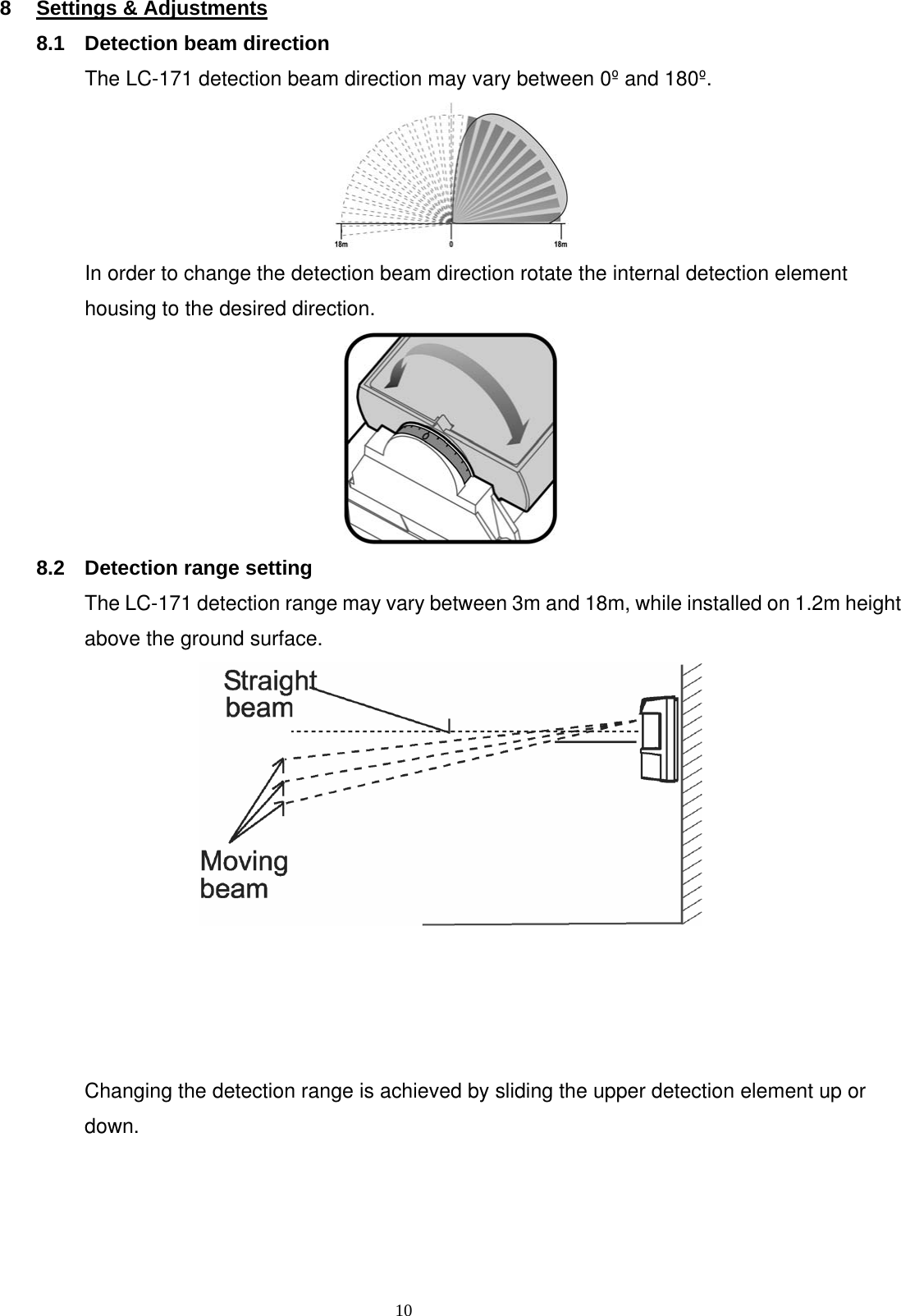
![9 7 Terminal Block Connections Terminal 1 - Marked “-” (GND) - Connect to the ground of the Control Panel. Terminal 2 - Marked “+” (+12V) - Connect to a positive Voltage of 9.6 -16Vdc source (usually from the Control Panel) Terminals 3 & 4 - Marked “TAMP” - If a Tamper function is required connect these Terminals to a normally closed 24-Hour Tamper Zone on the Control Panel. If the top cover of the detector is opened or the detector is detached from installation wall, an immediate alarm signal will be sent to the Control Panel. Terminal 5 - Marked “EOL” - End of line – optional terminal for end of line resistors connections. Terminals 6, 7 & 8 - Marked “NC / C / NO” - These are the output relay contacts of the detector. Connect to a zone input on the control unit. When an intruder is detected, alarm relays (N.C. and N.O.) will switch for 1.8 sec. 7.1 Wire Size Requirements Use #22 AWG or larger wires. Use the following table to determine required wire gauge and length. Wire Length [m] 205 310 510 870 Wire Length [ft.] 800 1200 2000 3400 Wire Gauge [#] 22 20 18 16](https://usermanual.wiki/Tyco-Safety-Canada/09LC171/User-Guide-1064894-Page-9.png)