Tyco Safety Canada 09RFK55M Alarm System Keypad with Wireless Receiver User Manual 29007608R001 RFK5501 5500 1 1 INIS EN
Digital Security Controls Ltd. Alarm System Keypad with Wireless Receiver 29007608R001 RFK5501 5500 1 1 INIS EN
UserManual.wiki
>
Tyco Safety Canada
>
09RFK55M User Manual
user manual
Navigation menu
Upload a User Manual
Namespaces
Wiki Guide
HTML
PDF
Info
Views
User Manual
Discussion / Help
Navigation
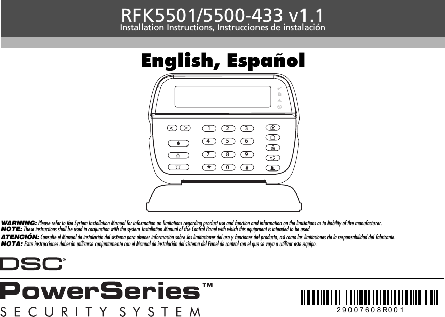
![The RFK5501/5500 keypads can be used on security systems with upto 64 zones. These keypads are compatible with the latest version ofthe folllowing DSC security systems:The RFK5501/5500 keypads combine a wireless receiver with therespective keypad.Specifications• Temperature range: -10°C to +55°C (14°F to 131°F), Temperaturerange for UL/ULC: 0°C to +49°C (32°F to 120°F)• Humidity (MAX): 93%R.H.• Plastic enclosure protection degree: IP30, IK04• Voltage rating: 12VDC nominal• Connects to control panel via 4-wire Keybus• 1 keypad zone input/PGM output*• Current draw: 75mA (standby)/135mA (maximum)• Wall mount tamper• 5 programmable function keys• Ready (Green LED), Armed (Red LED), Trouble (Yellow LED), AC (Green LED)• Low temperature sensor• Frequency: 433.92MHz • Up to 32 wireless zonesNOTE: * Zone not to be programmed as Fire type or 24h type.UnpackingThe Power keypad package includes the following parts:PlacementThe RFK5501/5500 performs best in locations where RF interferenceis minimal. To find an optimal mounting location for the keypad, per-form the following placement test:Step 1- Temporarily connect the Keybus wires to the keypad (refer towiring instructions).Step 2- Hold the keypad in the intended mounting location.Step 3- Enter keypad programming mode by pressing [4][8][installercode], then enter section[904].Step 4- If the yellow Trouble LED is on, interference levels are high anda new mounting location should be found. If the LED is flashing or off,interference is low and the location is good.MountingYou should mount the keypad where it is accessible to designatedpoints of entry and exit. Once you have selected a dry and secure loca-tion, perform the following steps to mount the keypad.Disassemble Keypad1. Insert a flat head screwdriver into the provided slot (first of two) 2. Move screwdriver toward the back plastic and lift as in the belowdiagram. This will unhook one side of the front plastic.3. Repeat step # 1 and 2 on the second provided slot to disconnectthe front plastic and allow access for wiring.Mount and Wire Keypad1. Secure Keypad to wall using mounting holes. Use all 4 screws providedunless mounting on a single gang box.2. Place keypad into hooks on the backplate and swing down to engage.3. Run wire through wiring slot or knockouts. Connect Keybus and PGM/Zonewiring to keypad. Place tamper switch into tamper hole on backplate.4. Remove keypad from hooks. Place keypad into backplate, ensure the wireis pushed back into the wall as much as possible. Route the wire insidethe keypad ensuring high components are avoided. Snap the front assem-bly closed, ensuring that there is no pressure to the keypad from the wirebelow.NOTE: If any tension found between the front keypad assembly and wiring,please open the keypad reroute the wire and close again. Repeat thesesteps until the keypad is closed properly.Wiring1. Before wiring the unit, ensure that all power (AC transformer and battery)is disconnected from the control panel.2. Connect the four Keybus wires from the con-trol panel (red, black, yellow and green) tothe keypad terminals. Refer to diagram:3. If programmed as an input, you can con-nect a device - such as a door contact - tothe ‘P/Z’ terminal of the keypad. This elim-inates the need to run wires back to thecontrol panel for the device. To connect thezone, run one wire from the device to the ‘P/Z’ terminal and the other wirefrom the device to the B (black) terminal. For powered devices, run the redwire to the R (positive) terminal and the black wire to the B (negative)terminal. When using end of line supervision, connect the zone accordingto one of the configurations outlined in your system’s Installation Manual. 4. If the ‘P/Z’ terminal is programmed as an output, the output follows thePGM programmed in Section [080]. A small relay, buzzer or other DCEnglishInstallation Instructions•PC580 •PC585 •PC1555MX •PC1565•PC1616 •PC1832 •PC1864 •PC5005•PC5008 •PC5010 •PC5015 •PC5016•PC5020•One Power keypad •Keypad inner door labels•Four mounting screws •1 tamper switch•2 end-of-line resistors •Installation Instructions1 23 Knock OutKnock OutKnock OutWiring SlotTamperHooksSwingto engagePress to Snap1. 2.3. 4.Ta m p e rHooksRFK5501/5500RED BLK YEL GRN To zone or PGM output](https://usermanual.wiki/Tyco-Safety-Canada/09RFK55M/User-Guide-1192765-Page-2.png)
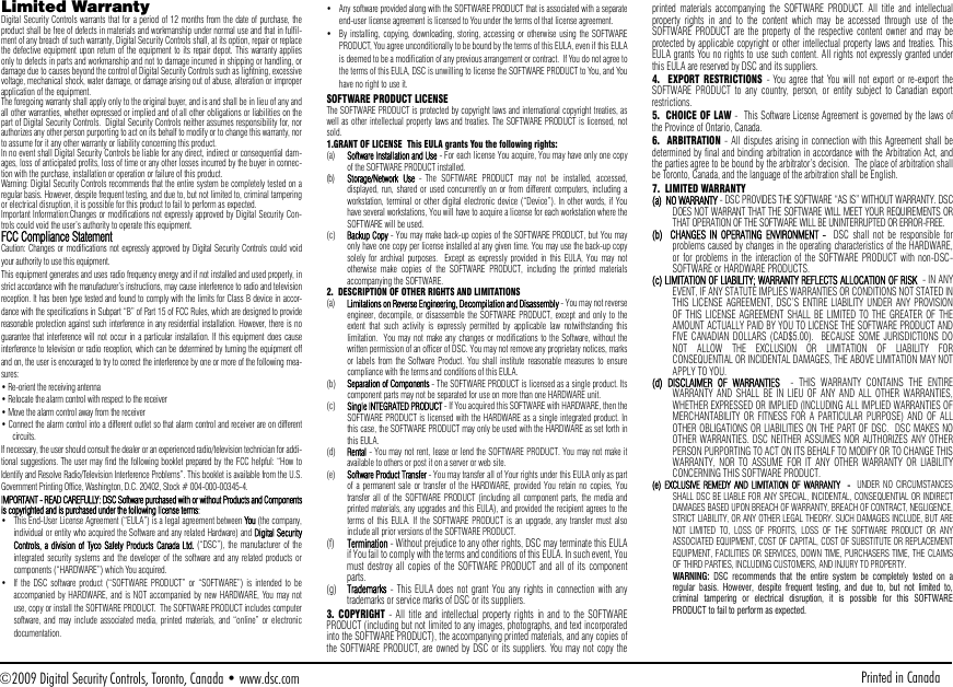
![operated device may be connected between the positive supply voltageand the ‘P/Z’ terminal (maximum load is 50mA).NOTE: For UL Residential Fire Installations use at least one additional DSCcompatible keypad in conjunction with an RFK5501/5500-433 keypad orinstall the RFK5501/5500-433 keypads within 3 feet from the control unitand mechanically protect the keybus wiresApplying PowerOnce all wiring is complete, and the equipment is secured to the buildingstructure with at least two screws apply power to the control panel:1. Connect the battery leads to the battery.2. Connect the AC transformer. For more information on control panel power specifications, see the controlpanel Installation Manual.Programming the KeypadThere are several programmingoptions available for the keypad.These are described below. Pro-gramming the keypad is similarto programming the rest of thesystem. When you are in the key-pad programming sections, thekeypad will display whichoptions are turned on along thetop of the display. To turn anoption on or off, press the num-ber corresponding to the optionon the number pad. The numbers of the options that are currently turnedON will be displayed. For example, if options 1 and 4 are on, the displaywill look like diagram shown on the different keypad displays. For information on programming the rest of your security system, pleaserefer to your system’s Installation Manual.Broadcasting LCD LabelsAll LCD programming is done per keypad. If more than one LCD keypad ispresent on the system, labels programmed at one keypad can be broadcastto all other LCD keypads. Perform the following procedure in order to broad-cast labels:Step 1 - Program one LCD keypad completely.Step 2 - Make sure all LCD keypads are connected to the Keybus.Step 3 - Enter keypad programming by pressing [4][8][InstallerCode][4], then enter section [998] at the keypad that was programmed.The keypad will now broadcast all the information programmed to all theother LCD keypads on the system.Step 4 - When the keypad is finished press the [#] key to exit.NOTE: LCD Label broadcast from this keypad is only compatiblewith other RFK5501/5500 Keypads.Language Programming Hold (<>) keys for 2 seconds to enter language programming, scroll tothe desired language and Press [4] to select.NOTE: If section [077] option 4 is OFF, language programmingcan only be performed while in installers programming.Enrolling the KeypadThe keypad will need to be assigned to a partition and slot if supervision orkeypad zones are being used. Keypad assignments and keypad option pro-gramming must be done at each keypad individually.The 1st digit of keypad assignment is used to determine partition assign-ment (1 to 8). If partitioning is not used, enter [1]. For Global Keypads,enter [0].NOTE: LED and ICON keypads cannot be programmed as Global KeypadsThe 2nd digit of keypad assignment is used to determine slot assignmentfor keypad supervision. Each keypad will be assigned a different slot num-ber from 1 to 8. RFK5501/5500 LCD keypads come defaulted in slot 8. IfLCD keypads are used one LCD keypad must remain in slot 8.NOTE: The keypad enrolls as two modules:Light 1 = keypad section Light 17 = receiver section NOTE: Deleting all wireless devices from the keypad or defaulting the key-pad will cause a supervisory fault.Enter the following at each keypad installed on the system:1. Enter Installer Programming by pressing [4][8][Installer’s Code]2. Press [000] for Keypad Programming3. Press [0] for Partition and Slot Assignment4. Enter the 1st digit (0 to 8 for partition assignment)5. Enter the 2nd digit (1 to 8 for slot assignment supervision)6. Press the [#] key twice to exit programming.7. After assigning all keypads, perform a supervisory reset by entering[4][8][Installer’s Code][902] and wait for 60 seconds.8. Press the [#] key to exit programming after 60 seconds.Programming Labels 1. Enter keypad programming by pressing [4][8][Installer Code][4]. Enterthe 3-digit section number for the label to be programmed.2. Use the arrow keys (<>) to move the underline bar underneath the let-ter to be changed. 3. Press the number keys [1] to [9] corresponding to the letter you require.The first time you press the number the first letter will appear. Pressing thenumber key again will display the next letter.4. When the required letter or number is displayed use the arrow keys(<>) to scroll to the next letter.5. When you are finished programming the Zone Label, press the [4] key,scroll to “Save,” then press [4].6. Continue from Step 2 until all Labels are programmed.ASCII CharactersChanging Brightness/ContrastLCD Keypads1. Press [4][6][Master code].2. Use the [<][>] keys to scroll to either Brightness Control or Contrast Control.3. Press [4] to select the setting you want to adjust.4. a) ‘Brightness Control’: There are multiple backlighting levels. Use the [<][>]keys to scroll to the desired level.b) ‘Contrast Control’: There are 10 different display contrast levels. Use the[<][>] keys to scroll to the desired contrast level.5. To exit, press [#].LED/ICON Keypads1. Press [4][6][Master Code].2. Use the [>] key to move through the 4 different backlighting levels.3. The level is automatically saved when you press [#] to exit.Changing the Buzzer LevelLCD Keypads1. Press [4][6][Master Code].2. Use the [<][>] keys to scroll to Buzzer Control.3. There are 21 different levels, use the [<][>] keys to scroll to the desired level.4. To exit, press [#].LED/ICON Keypads1. Press [4][6][Master Code].2. Use the [<] key to move through the 21 different buzzer levels.3. The level is automatically saved when you press [#] to exit.Broadcasting Door ChimeAll door chime programming is done per keypad. If more than one keypad ispresent on the system, door chime programmed at one keypad can be broad-cast to all other keypads. Perform the following procedure in order to broadcastdoor chime:Step 1 - Program one keypad completely.Step 2 - Make sure all keypads are connected to the Keybus.Step 3 - Enter keypad programming by pressing [4][8][Installer Code][4], thenenter section [994] at the keypad that was programmed. The keypad willnow broadcast all the door chime information programmed to all theother keypads on the system.Step 4 - When the keypad is finished press the [#] key to exit.41Toggle Option1 _ _ 4 _ _ _ _[1] - A, B, C, 1 [4] - J, K, L, 4 [7] - S, T, U, 7 [0] - Space[2] - D, E, F, 2 [5] - M, N, O, 5 [8] - V, W, X, 8[3] - G, H, I, 3 [6] - P, Q, R, 6 [9] - Y, Z, 9,0](https://usermanual.wiki/Tyco-Safety-Canada/09RFK55M/User-Guide-1192765-Page-3.png)
![Keypad EnrollmentEnter keypad programming by pressing [4][8][Installer’s Code][000].[0] Partition / Slot Assignment[1]-[5] Function Key AssignmentKeypad Function KeysRefer to your system installation manual for a complete list of all function key options available for your system.Keypad ProgrammingEnter keypad programming by pressing [4][8][Installer Code][4][001]-[064] Zone Label 1 to 64 (PK5500\RFK5500 Only)ex. For Zone 1 enter section [001], for Zone 2 enter section [002] etc. Default: “Zone 1” - “Zone 64”[065] Fire Alarm Label (28 Characters) Default:“Fire Zone”[066] Fail to Arm Event MessageDefault: “System Has Failed to Arm”[067] Alarm When Armed Event Message Default: “Alarm Occurred While Armed < >”[071] First User Display Mask[072] Second User Display Mask[073] Download LCD Message Duration Default: 003 I_____I_____I_____I (Valid entries are 000-255), 000=Unlimited Message Disp.This number represents the number of times the Downloaded message is cleared by pressing any key while the message is up after timeout).Digit Option Valid Range Default1st Partition Assignment (0=Global Keypad) 0 to 8 1 I_____I2nd Slot Assignment 1 to 8 LED,ICON=1/LCD=8 I_____IFunction Key Button Valid Range Default Function[1] Function Key 1 Assignment 00 to 32 03 Stay Arm I_____I_____I[2] Function Key 2 Assignment 00 to 32 04 Away Arm I_____I_____I[3] Function Key 3 Assignment 00 to 32 06 Chime On/Off I_____I_____I[4] Function Key 4 Assignment 00 to 32 14 Sensor Reset I_____I_____I[5] Function Key 5 Assignment 00 to 32 16 Quick Exit I_____I_____I[00] - Null [08] - Bypass Mode [16] - Quick Exit [26] - Time & Date Program[01] - Partition 1 Select [09] - Trouble Display [17] - Activate Stay/Away [27] - Partition 3 Select[02] - Partition 2 Select [10] - Alarm Memory [18] - *Global Away Arm [28] - Partition 4 Select[03] - Stay Arm [11] - User Programming [19] - Command Output 3 [29] - Partition 5 Select[04] - Away Arm [12] - User Functions [21] - Command Output 4 [30] - Partition 6 Select[05] - No Entry Arm [13] - Command Output 1 [22] - *Global Disarming [31] - Partition 7 Select[06] - Chime On/Off [14] - Command Output 2 [23] - Bypass Recall [32] - Partition 8 Select[07] - System Test [15] - *Global Stay Arm [24] - Bypass Group Recall [33] - Local PGM Activate*Available only on the PC1616/PC1832/PC1864 version 4.2 or higher.Section Zone Label[001] to [064] 1 to 64 I_____I_____I_____I_____I_____I_____I_____I_____I_____I_____I_____I_____I_____I_____II_____I_____I_____I_____I_____I_____I_____I_____I_____I_____I_____I_____I_____I_____I[065] I_____I_____I_____I_____I_____I_____I_____I_____I_____I_____I_____I_____I_____I_____II_____I_____I_____I_____I_____I_____I_____I_____I_____I_____I_____I_____I_____I_____I[066] I_____I_____I_____I_____I_____I_____I_____I_____I_____I_____I_____I_____I_____I_____I_____I_____II_____I_____I_____I_____I_____I_____I_____I_____I_____I_____I_____I_____I_____I_____I_____I_____I[067] I_____I_____I_____I_____I_____I_____I_____I_____I_____I_____I_____I_____I_____I_____I_____I_____II_____I_____I_____I_____I_____I_____I_____I_____I_____I_____I_____I_____I_____I_____I_____I_____IDefault Option ON OFFON I____I 1 Hold [P]anic Key prompt ON Hold [P]anic Key prompt OFFON I____I 2 Auto-arm Control/Time prompt ON Auto-arm Control/Time prompt OFFON I____I 3 Quick Arm prompt ON Quick Arm prompt OFFON I____I 4 Interior Arm prompt ON Interior Arm prompt OFFOFF I____I 5 Quick Exit prompt ON Quick Exit prompt OFFOFF I____I 6 Thermostat Control prompt ON Thermostat Control prompt OFFOFF I____I 7 ACK All Trouble Prompt ON ACK All Trouble Prompt OFFOFF I____I 8 Music Input prompt ON Music Input prompt OFFDefault Option ON OFFON I____I 1 User-initiated Call-up prompt ON User-initiated Call-up prompt OFFOFF I____I 2For Future UseOFF I____I 3 Walk Test prompt ON Walk Test prompt OFFON I____I 4 Command Output#1 prompt ON Command Output#1 prompt OFFON I____I 5 Command Output#2 prompt ON Command Output#2 prompt OFFOFF I____I 6 Command Output#3 prompt ON Command Output#3 prompt OFFOFF I____I 7 Command Output#4 prompt ON Command Output#4 prompt OFFOFF I____I 8For Future Use](https://usermanual.wiki/Tyco-Safety-Canada/09RFK55M/User-Guide-1192765-Page-5.png)
![[074] Key Options[076] First Keypad Options[077] Second Keypad Options[080] PGM Terminal 1Default: 01 I_______I _______I 1-14 Follow PGM Output Number, 15 Local PGM Pulse , 16 Local PGM Toggle[082] Local PGM Output Pulse Activation TimeDefault: 00 I_______I _______I Minutes (Valid Range 00-99)Default: 05 I_______I _______I Seconds (Valid Range 00-99)[101]-[108] Partition Labels (PK5500\RFK5500 Only)ex. For Partition 1 enter section [101], for Partition 2 enter section [102] etc.NOTE: Partition 1 Label is also used as the System Label[120]-[151] Command Output Labels Default: “Command_O/P_1” - “Command_O/P_4”[201]-[264] Door Chime Sound ProgrammingYou can program the keypad to make up to four different door chime sounds for individual zones.ex. For Zone 1 enter section [201], for Zone 2 enter section [202] etc.[994][Q] Initiate Global Keypad Chime Broadcast[995][4] Reset Keypad Options to Factory Default[996][4] Label Default[997] View Software Version [998][4] Initiate Global Label Broadcast [999][4] Reset Keypad EEPROM to Factory DefaultsKeypad Display SymbolsDefault Option ON OFFON I____I 1 [F]ire Key Enabled [F]ire Key DisabledON I____I 2 [A]uxiliary Key Enabled [A]uxiliary Key DisabledON I____I 3 [P]anic Key Enabled [P]anic Key DisabledOFF I____I 4-8 For Future UseDefault Option ON OFFON I____I 1 Display Code when Programming Display “Xs” when ProgrammingON I____I 2 Local Clock Display ON Local Clock Display OFFOFF I____I 3 Local Clock Displays 24-hr Time Local Clock Displays AM/PMON I____I 4 Auto Alarm Memory Scroll Enabled Auto Alarm Memory Scroll DisabledOFF I____I 5 Local Display of Temperature ON Local Display of Temperature OFFON I____I 6 Bypass Options prompt ON Bypass Options prompt OFFOFF I____I 7For Future UseOFF I____I 8 Auto-Scroll Open Zones ON Auto-Scroll Open Zones OFFDefault Option ON OFFON I____I 1 Chime Enabled for Zone Openings Chime Disabled for Zone OpeningsON I____I 2 Chime Enabled for Zone Closings Chime Disabled for Zone ClosingsOFF I____I 3 5th Terminal is Keypad PGM Output 5th Terminal is Keypad Zone InputON I____I 4 Language Selection Enabled Language Selection DisabledOFF I____I 5 Power LED Enabled Power LED DisabledON I____I 6 Power LED indicates AC present Power LED indicates AC absentON I____I 7 Alarms always Displayed When Armed Alarms not Displayed When ArmedOFF I____I 8 Low Temperature Warning Enabled Low Temperature Warning DisabledSection Partition Label[101] to [108] 1 to 8 I_____I_____I_____I_____I_____I_____I_____I_____I_____I_____I_____I_____I_____I_____II_____I_____I_____I_____I_____I_____I_____I_____I_____I_____I_____I_____I_____I_____IFor Partition 1 Command O/P 1 to 4 enter [120] to [123] For Partition 5 Command O/P 1 to 4 enter [136] to [139]For Partition 2 Command O/P 1 to 4 enter [124] to [127] For Partition 6 Command O/P 1 to 4 enter [140] to [143]For Partition 3 Command O/P 1 to 4 enter [128] to [131] For Partition 7 Command O/P 1 to 4 enter [144] to [147]For Partition 4 Command O/P 1 to 4 enter [132] to [135] For Partition 8 Command O/P 1 to 4 enter [148] to [151]Section Part Cmd.Output Label[120]-[151]1to8 1to4 I_____I_____I_____I_____I_____I_____I_____I_____I_____I_____I_____I_____I_____I_____II_____I_____I_____I_____I_____I_____I_____I_____I_____I_____I_____I_____I_____I_____IDefault Option ON OFFON I____I 1 6 Beeps DisabledOFF I____I 2 “Bing-Bing” Sound DisabledOFF I____I 3 “Ding-Dong” Sound DisabledOFF I____I 4Alarm Tone DisabledOFF I____I 5-8 For Future Use8Bypass – Indicates that there are zones automatically or manually bypassed.9For Future Use10 Arm Mode – Indicates the mode the panel is armed in.Stay – Indicates that the panel is armed in the Stay Mode. It will turn on at the beginning of the Exit Delay1Fire – Indicates that there are fire alarms in memory.2Memory – Indicates that there are alarms in memory. Away – Indicates that the panel is armed in the Away Mode. It will turn on at the beginning of the Exit Delay3Ready Light (green) – If the Ready light is on, the system is ready for arming.4Armed Light (red) – If the Armed light is on, the system has been armed successfully. 11 Chime – This icon turns on when Door Chime is enabled on the system and will turn off when Door Chime is disabled.5System Trouble – Indicates that a system trouble is active.12 Open – When zones are opened, this icon will turn on, and 7 segment displays 1 and 2 will scroll through the open zones.6AC – Indicates that AC is present at the main panel.7Program – Indicates that the system is in Installer’s Pro-gramming, or the keypad is busy.1234567812 9101112 78](https://usermanual.wiki/Tyco-Safety-Canada/09RFK55M/User-Guide-1192765-Page-6.png)
![Wireless Integration Compatible Wireless Devices The RFK5501/5500 can receive signals from the following devices:DownloadingThe RFK5501/5500 has an integrated wireless receiver. When down-loading to this keypad, please select the PC5132-433 v5.2 file.DLS2002 must be used in order to have the capability of downloadingto this keypad.Testing Wireless Devices1. Temporarily put the wireless devices in the places you want tomount them.2. At a system keypad, enter [4][8][Installer Code].3. Enter programming section [904], then enter the 2-digit zonenumber.NOTE: If global placement test is enabled (Section [90], option 8ON) enter [01] to test all zones.4. Activate the device being tested until a result is displayed on thekeypad or sounded by the keypad or bellWhile in placement test the Ready and Armed LEDs are used to indi-cate the reception of a valid signal from a wireless device. The Green(Ready) LED indicates that a transmission was received from a devicethat is enrolled on the system. The Red (Armed) LED indicates that atransmission was received from a device that is not enrolled on thesystem. The corresponding LED will flash once per transmission. Activate the device until you get 3 good results in a row. Wait 10 sec-onds between each test on the same device. You may mount wirelessdevices where results were good.Devices indicating a bad result must be moved to another location.You may only have to move the device a few inches to correct a badresult.NOTE: Do not mount any device where a “bad” test result wasindicated.Testing Portable Device ReceptionTo test portable devices (e.g., WS4938, WS4939) press the button(s)at several different points in the installation, to confirm the coveragearea. If these devices do not operate from all points in the installation,you will need to move the RFK5501/5500.Replacing Wireless Device Batteries1. Remove the cover of the device from its backplate. This creates atamper condition on the zone.2. Refer to the battery installation instructions on the InstallationSheet of each component. Be sure to note the proper orientation ofthe batteries as you install them.3. When the fresh batteries are in place, re-attach the cover to thebackplate. The tamper is restored and the zone sends a batterytrouble restoral signal to the receiver. The battery trouble is nowclear and the device should function normally.NOTE: When batteries in one device need to be replaced, the bat-teries in all devices should be replaced at the same time.Troubleshooting1. When I enter the 2-digit zone number when adding a wirelessdevice, the keypad gives me a long beep.• You cannot enter ESNs unless the keypad is properly connected to theKeybus.2. I have entered the ESN for the device but when I violate the device,the zone does not show open on the keypad.Check the following:• Ensure the ESN has been entered correctly• Ensure that the zone is enabled for the partition (if partition program-ming is used).• Ensure that the wireless zone is not assigned to a zone used byPC5108 modules, an on-board zone or a keypad zone.• Ensure that the zone is programmed for something other than “NullOperation” and that the wireless zone attribute is turned on.3. When I try a module placement test I get no result or “Bad” results.Check the following:• Verify that you are testing the correct zone• Verify that the correct ESN was entered when the device was enrolled• Verify that the device is in range of the keypad. Try testing the devicein the same room as the receiver.• Confirm that the keypad is properly connected to the Keybus.• Check that you are testing the zone correctly. Refer to the instructionsthat came with the zone.• Check that the batteries are working and installed correctly.• Look for large metal objects that may be preventing the signal fromreaching the keypad.• The device must be located where consistent “Good” results areobtained. If several devices show “Bad” results, or if panic pendantsand wireless keys operate inconsistently, move the receiver.4. The LED on the motion detector does not turn on when I walk infront of the unit.• The LED on the motion detector is for walk test purposes only. Seeyour WLS904-433/WLS904P(L)-433 Instruction Sheet for walk testinstructions.Notes:•WLS914-433 Pet Immune PIR •WLS912L-433 Glass Break Detector•WS4965 Tri-Zone Contact •WLS904(P)L-433 Pet Immune PIR•WS4938 Panic Button •WLS925L-433 Mini Door/Window Contact•WS4916 Smoke Detector •WS49X9 Wireless KeysResult LED/ICON Keypad LCD Keypad Bell/BuzzerGood Light 1 ON Steady Good 1 Beep/SquawkBad Light 3 ON Steady Bad 3 Beeps/Squawks](https://usermanual.wiki/Tyco-Safety-Canada/09RFK55M/User-Guide-1192765-Page-7.png)
![Wireless Programming Enter Wireless programming by pressing [4][8][Installer’s Code][804][01]-[32] Wireless Device Serial Number Zone Serial Numbers Default = 000000[41]-[56] Wireless Key Serial Number Wireless Key Serial Numbers Default = 000000[61]-[76] Wireless Function Key OptionsKeypad Function KeysPlease see your system installation manual for a complete list of all the function key options available for your system.[77] Wireless Keys (1-16) Partition Assignments Default = 01[81] Wireless supervisory WindowDefault: [NA] 96 = 24 hours / [EU] 10 =2.5 hours I_____I_____IThe window is programmed in 15 minute increments. Valid entries are 10 to 96, equal to 2.5 to 24 hours.[82]-[85] Zone Device Supervision Options[90] Other OptionsNOTE: For UL Listed installations, the RF Jam detect feature must be enabled.NOTE: For DD243 installations, the RF delinquency feature should be enabled.NOTE: Supervision must be enabled for RF Delinquency.[93] RF Jam Detect ZoneDefault: 00 I_____I_____I Valid entries = 01 - 32, 00 = No RF Jam tone selected.Select an unused zone that will be set to the tamper state when a jamming signal is detected.[01] Zone 1 I_____I_____I_____I_____I_____I_____I [17] Zone 17 I_____I_____I_____I_____I_____I_____I[02] Zone 2 I_____I_____I_____I_____I_____I_____I [18] Zone 18 I_____I_____I_____I_____I_____I_____I[03] Zone 3 I_____I_____I_____I_____I_____I_____I [19] Zone 19 I_____I_____I_____I_____I_____I_____I[04] Zone 4 I_____I_____I_____I_____I_____I_____I [20] Zone 20 I_____I_____I_____I_____I_____I_____I[05] Zone 5 I_____I_____I_____I_____I_____I_____I [21] Zone 21 I_____I_____I_____I_____I_____I_____I[06] Zone 6 I_____I_____I_____I_____I_____I_____I [22] Zone 22 I_____I_____I_____I_____I_____I_____I[07] Zone 7 I_____I_____I_____I_____I_____I_____I [23] Zone 23 I_____I_____I_____I_____I_____I_____I[08] Zone 8 I_____I_____I_____I_____I_____I_____I [24] Zone 24 I_____I_____I_____I_____I_____I_____I[09] Zone 9 I_____I_____I_____I_____I_____I_____I [25] Zone 25 I_____I_____I_____I_____I_____I_____I[10] Zone 10 I_____I_____I_____I_____I_____I_____I [26] Zone 26 I_____I_____I_____I_____I_____I_____I[11] Zone 11 I_____I_____I_____I_____I_____I_____I [27] Zone 27 I_____I_____I_____I_____I_____I_____I[12] Zone 12 I_____I_____I_____I_____I_____I_____I [28] Zone 28 I_____I_____I_____I_____I_____I_____I[13] Zone 13 I_____I_____I_____I_____I_____I_____I [29] Zone 29 I_____I_____I_____I_____I_____I_____I[14] Zone 14 I_____I_____I_____I_____I_____I_____I [30] Zone 30 I_____I_____I_____I_____I_____I_____I[15] Zone 15 I_____I_____I_____I_____I_____I_____I [31] Zone 31 I_____I_____I_____I_____I_____I_____I[16] Zone 16 I_____I_____I_____I_____I_____I_____I [32] Zone 32 I_____I_____I_____I_____I_____I_____I[41] Key 1 I_____I_____I_____I_____I_____I_____I [49] Key 9 I_____I_____I_____I_____I_____I_____I[42] Key 2 I_____I_____I_____I_____I_____I_____I [50] Key 10 I_____I_____I_____I_____I_____I_____I[43] Key 3 I_____I_____I_____I_____I_____I_____I [51] Key 11 I_____I_____I_____I_____I_____I_____I[44] Key 4 I_____I_____I_____I_____I_____I_____I [52] Key 12 I_____I_____I_____I_____I_____I_____I[45] Key 5 I_____I_____I_____I_____I_____I_____I [53] Key 13 I_____I_____I_____I_____I_____I_____I[46] Key 6 I_____I_____I_____I_____I_____I_____I [54] Key 14 I_____I_____I_____I_____I_____I_____I[47] Key 7 I_____I_____I_____I_____I_____I_____I [55] Key 15 I_____I_____I_____I_____I_____I_____I[48] Key 8 I_____I_____I_____I_____I_____I_____I [56] Key 16 I_____I_____I_____I_____I_____I_____IFunction 1Default 03Function 2Default 04Function 3Default 27Function 4Default 30Function 1Default 03Function 2Default 04Function 3Default 27Function 4Default 30[61] Key 1 I_____I_____I I_____I_____I I_____I_____I I_____I_____I [69] Key 9 I_____I_____I I_____I_____I I_____I_____I I_____I_____I[62] Key 2 I_____I_____I I_____I_____I I_____I_____I I_____I_____I [70] Key 10 I_____I_____I I_____I_____I I_____I_____I I_____I_____I[63] Key 3 I_____I_____I I_____I_____I I_____I_____I I_____I_____I [71] Key 11 I_____I_____I I_____I_____I I_____I_____I I_____I_____I[64] Key 4 I_____I_____I I_____I_____I I_____I_____I I_____I_____I [72] Key 12 I_____I_____I I_____I_____I I_____I_____I I_____I_____I[65] Key 5 I_____I_____I I_____I_____I I_____I_____I I_____I_____I [73] Key 13 I_____I_____I I_____I_____I I_____I_____I I_____I_____I[66] Key 6 I_____I_____I I_____I_____I I_____I_____I I_____I_____I [74] Key 14 I_____I_____I I_____I_____I I_____I_____I I_____I_____I[67] Key 7 I_____I_____I I_____I_____I I_____I_____I I_____I_____I [75] Key 15 I_____I_____I I_____I_____I I_____I_____I I_____I_____I[68] Key 8 I_____I_____I I_____I_____I I_____I_____I I_____I_____I [76] Key 16 I_____I_____I I_____I_____I I_____I_____I I_____I_____I[00] - Null [07] - System Test [17] - Activate Stay/Away [27] - Disarm[03] - Stay Arm [13] - Command Output 1 [18] - Global Away Arm [28] - Fire Alarm[04] - Away Arm [14] - Command Output 2 [19] - Command Output 3 [29] - Auxiliary Alarm[05] - No Entry Arm [15] - Global Stay Arm [21] - Command Output 4 [30] - Panic Alarm[06] - Chime On/Off [16] - Quick Exit [22] - Global Disarm [31] - Local PGM ActivateNOTE: Wireless keys must have an access code for global arm/disarm function.Key 1 I_____I_____I Key 5 I_____I_____I Key 9 I_____I_____I Key 13 I_____I_____IKey 2 I_____I_____I Key 6 I_____I_____I Key 10 I_____I_____I Key 14 I_____I_____IKey 3 I_____I_____I Key 7 I_____I_____I Key 11 I_____I_____I Key 15 I_____I_____IKey 4 I_____I_____I Key 8 I_____I_____I Key 12 I_____I_____I Key 16 I_____I_____IDefault ON [82]ZoneSupervision ON/OFF[83]ZoneSupervision ON/OFF[84]ZoneSupervision ON/OFF[85]ZoneSupervision ON/OFFOption 1 1 I_____I 9I_____I 17 I_____I 25 I_____IOption 2 2 I_____I 10 I_____I 18 I_____I 26 I_____IOption 3 3 I_____I 11 I_____I 19 I_____I 27 I_____IOption 4 4 I_____I 12 I_____I 20 I_____I 28 I_____IOption 5 5 I_____I 13 I_____I 21 I_____I 29 I_____IOption 6 6 I_____I 14 I_____I 22 I_____I 30 I_____IOption 7 7 I_____I 15 I_____I 23 I_____I 31 I_____IOption 8 8 I_____I 16 I_____I 24 I_____I 32 I_____INA Default EU Default Option ON OFFOFF OFF I____I 1,2,4 For Future UseON OFF I____I 3 Wall Tamper Disabled Wall Tamper EnabledON OFF I____I 5 RF Delinquency Disabled RF Delinquency EnabledOFF OFF I____I 6For Future UseON OFF I____I 7 RF Jam Detect Disabled RF Jam Detect EnabledOFF OFF I____I 8 Global Placement Test Individual Placement Test](https://usermanual.wiki/Tyco-Safety-Canada/09RFK55M/User-Guide-1192765-Page-8.png)
![Los teclados RFK5501/5500 pueden utilizarse en sistemas de seguri-dad que contengan un máximo de 64 zonas. Estos teclados son com-patibles con las últimas versions de los siguientes sistemas DSC :Los teclados RFK5501/5500 combinan un receptor inalámbrico con elrespectivo teclado.Especificaciones• Intervalo de temperatura: de -10°C a +55°C (de 14°F a 131°F), Inter-valo de temperatura para UL/ULC: 0°C a +49°C (32°F a 120°F)• Humedad (máx): 93% de humedad relativa• Grado de protección del envoltorio de plástico: IP30, IK04• Tensión nominal: 12 VCC nominal• Se conecta a un panel de control a través de un Keybus de 4 cables• 1 teclado para entrada de zona/salida PGM*• Consumo de corriente: 50 mA (espera) / 125 mA (máximo)• Consumo de corriente: 75 mA (espera) / 135 mA (máximo)• Montaje en la pared - violación• 5 teclas de función programables• Preparado (LED verde), Armado (LED rojo), Problema (LED amarillo), CA(LED verde)• Sensor de baja temperatura• Frecuencia 433,92 MHz • Hasta 32 zonas inalámbricas * NOTA: Esta zona no debe programarse como tipo lncendio o tipo 24hDesembalajeEl paquete del teclado de potencia contiene los siguientes elementos:Prueba de localizaciónEl RFK5501/5500 funciona mejor en lugares donde la interferenciade RF es mínima. Para conseguir la ubicación mas óptima para elteclado, ejecute la siguiente prueba de localización:Paso 1- Conecte temporalmente los cables del keybus al teclado (con-sulte las instrucciones de cableado).Paso 2- Sostenga el teclado en el lugar en el que desea montarlo.Paso 3- Ingrese al modo de programación del teclado presionando[4][8][Código de Instalador], después ingrese a la sección [904]Paso 4- Si el LED amarillo de Fallo del Sistema está encendido, losniveles de interferencia son altos y se debe encontrar otro lugar para elmontaje del teclado. Si el LED está iluminado de manera intermitente,la interferencia es baja y el lugar de montaje es bueno.MontajeDeberá montarse el teclado en un lugar accesible para los puntos des-ignados de entrada y salida. Una vez seleccionada una ubicación secay segura, lleve a cabo los siguientes pasos para montar el teclado.Desmontaje del teclado1. Introduzca un destornillador de punta plana en la ranura inferior(primera de dos).2. Mueva el destornillador en la parte trasera tal y como muestra eldiagrama. Esto libera uno de los lados de la parte frontal.3. Repita los pasos 1 y 2 en la segunda ranura para liberar totalmentela parte frontal y permitir el acceso a las conexiones Montaje e cableado del teclado1. Fije el teclado en la pared utilizando perforaciones de montaje. Utilice loscuatro tornillos proveidos, a menos que el montaje sea hecho en una solacaja de acoplaje.2. Coloque el teclado en los ganchos de la placa de apoyo y gírelo haciaabajo para encajar.3. Pase el cable por la ranura de cableado o perforaciones de salida. Conectelos cables de Keybus y PGM/Zona al teclado. Coloque el interruptor de vio-lación en la perforación de violación de la placa de apoyo.4. Remova el teclado de los ganchos. Coloque el teclado en la placa deapoyo, certifíquese de que el cable sea empujado hacia la pared lo máxi-mo posible. Pase el cable por dentro del teclado, certifíquese que los com-ponentes de arriba sean evitados. Cierre el conjunto frontal, garantizandoque no haya presión del cable abajo sobre el teclado.NOTA: Si fuere detectada cualquier tensión entre el conjunto del tecladofrontal y el cableado, abra el teclado, repase el cable y cierre lo nueva-mente. Repita esos procedimientos hasta que el teclado esté cerrado ade-cuadamente.EspañolInstrucciones de instalación•PC580 •PC585 •PC1555MX •PC1565•PC1616 •PC1832 •PC1864 •PC5005•PC5008 •PC5010 •PC5015 •PC5016•PC5020•Un teclado de potencia •Etiquetas de la puerta interior del teclado•Cuatro tornillos de montaje •Un interruptor contra sabotajes•Dos resistencias de fin de línea •Instrucciones de instalación1 23 Orificio de salidaOrificio desalidaOrificio desalidaranura decableadoviolaciónganchosgire haciaencajarpresione para fijar1. 2.3. 4.violaciónganchos](https://usermanual.wiki/Tyco-Safety-Canada/09RFK55M/User-Guide-1192765-Page-9.png)
![Cableado1. 1. Antes de realizar el cableado de la unidad, asegúrese de que laalimentación (transformador de CA y batería) está desconectada delpanel de control.2. Conecte los cuatro cables del Keybusdesde el panel de control (rojo, negro,amarillo y verde) a los bornes delteclado. Consulte el diagrama:3. Si va a ser programado como unaentrada, puede conectar un dispositivo(por ejemplo, un contacto de puerta) alborne ‘P/Z’ del teclado. De esta manera se elimina la necesidad dellevar cables de vuelta al panel de control para el dispositivo. Paraconectar la zona, lleve un cable desde el dispositivo al borne ‘P/Z’, yel otro cable desde el dispositivo hasta el borne B (negro). Para dis-positivos alimentados, lleve el cable rojo al borne R (positivo) y elcable negro al borne B (negativo). Cuando utilice la supervisión definal de línea, conecte la zona de acuerdo con una de las configura-ciones descritas en el Manual de instalación del sistema. 4. Si el borne ‘P/Z’ está programado como una salida, la salida siguela PGM programada en la Sección [080]. Puede conectarse unpequeño relé, zumbador u otro dispositivo alimentado por CC entreel borne de tensión positiva y el borne ‘P/Z’ (la máxima carga es de50 mA).NOTA: Utilice para Instalaciones de Incendio Residenciales UL, por lo menos,un teclado adicional compatible DSC en conjunto con un teclado RFK5501/5500, o instale los teclados RFK5501/5500 a una distancia máxima de 90cm de la unidad de control y proteja los cables del bus del teclado mecánica-mente.Aplicación de la alimentaciónUna vez completado el cableado, y el equipo estuivere preso a laestructura del edificio con dos tornillos como mínimo, aplique la corri-ente eléctrica al panel de control:1. Conecte la batería a los terminales de la misma.2. Conecte el transformador de CA. Para más información sobre las especificaciones de alimentación delpanel de control, consulte el Manual de instalación del panel de con-trol.Programación del tecladoExisten varias opciones de pro-gramación disponibles para elteclado. Estas opciones sedescriben a continuación. Laprogramación del teclado essimilar a la programación delresto del sistema. Cuando seencuentre en las secciones deprogramación del teclado, éstemostrará las opciones activa-das en la parte superior de lapantalla. Para activar o desactivar una opción, pulse el número corre-spondiente a la opción en el teclado numérico. Se mostrarán losnúmeros de las opciones que estén activadas (ON) en ese momento.Por ejemplo, si las opciones 1 y 4 están activadas, la pantalla tendráel aspecto de una de las siguientes pantallas de teclado:Para más información sobre la programación del resto del sistema deseguridad, consulte el Manual de instalación del sistema. Transmisión de etiquetas a partir del LCDToda la programación de los teclados LCD se lleva a cabo en cadateclado independientemente. Si hay más de un teclado LCD presenteen el sistema, las etiquetas programadas en un teclado pueden serdifundidas a todo el resto de teclados LCD. Lleve a cabo el siguienteprocedimiento para transmitir etiquetas:Paso 1 - Programe un teclado LCD completamente.Paso 2 - Asegúrese de que todos los teclados LCD están conectados alKeybus.Paso 3 - Entre en la programación del teclado pulsando[4][8][Código del instalador][4], a continuación, entre en la sección[998] del teclado programado. Este teclado transmitirá entonces todala información programada a todo el resto de teclados LCD delsistema.Paso 4 - Una vez terminado el proceso, pulse la tecla [#] para salir.NOTA: La transmisión de etiquetas desde este teclado sólo es compatible conotros teclados RFK5501/5500.Programación del idioma Mantenga pulsadas las teclas (<>) durante 2 segundos para entraren la programación del idioma, avance hasta el idioma deseado ypulse [4] para seleccionarlo.NOTA: Si la opción 4 de la sección [077] está apagada (OFF), la progra-mación del idioma sólo podrá realizarse desde la programación del instala-dor.”Registro del tecladoDeberá asignarse el teclado a una partición y ranura en el caso de quese utilicen zonas de supervisión o de teclados. Las asignaciones delteclado y la programación de opciones del mismo deben realizarseindividualmente para cada teclado. La primera cifra de la asignacióndel teclado se utiliza para determinar la asignación de la partición (1a 8). En el caso de que no se utilicen particiones, introduzca [1]. Parateclados globales, introduzca [0].NOTA: Los teclados de LED e ICONOS no pueden ser programados comoteclados localesLa segunda cifra de la asignación del teclado se utiliza para determi-nar la asignación de ranura en la supervisión del teclado. A cadateclado se le asigna un número de ranura diferente, del 1 al 8. Losteclados LCD RFK5501/5500 se asignan por defecto a la ranura 8. Enel caso de que se utilicen teclados LCD, uno de éstos deberá perman-ecer en la ranura 8.NOTA: El RFK5501/5500 se registra como dos módulos:Luz 1 = sección del teclado del RFK5501/5500Liuz 17 = sección del receptor del RFK5501/5500NOTA: Si se eliminan todos los dispositivos inalámbricos del teclado, al con-figurar por defecto el teclado, se generará un aviso de fallo de supervisión.Introduzca los siguientes valores en cada teclado instalado en elsistema:1. Entre en la programación del instalador pulsando [4][8][Códigodel instalador]2. Pulse [000] para la programación del teclado3. Pulse [0] para la asignación de partición y ranura4. Introduzca la primera cifra (del 0 al 8, para la asignación de par-tición)5. Introduzca la segunda cifra (del 1 al 8, para la supervisión de laasignación de ranura)6. Pulse dos veces la tecla [#] para salir de la programación.7. Tras asignar todos los teclados, lleve a cabo un rearme de super-visión introduciendo [4][8][Código del instalador][902], y esperedurante 60 segundos.8. Pulse la tecla [#] para salir de la programación tras 60 segundos.PK55XX\RFK55XXROJNEGAMAVERA zone osalida PGMRBYGP/Z41Toggle Option1 _ _ 4 _ _ _ _](https://usermanual.wiki/Tyco-Safety-Canada/09RFK55M/User-Guide-1192765-Page-10.png)
![Programación de etiquetas 1. Entre en la programación del teclado pulsando [4][8][Código delinstalador][4]. Introduzca el número de sección de 3 cifras de laetiqueta a programar.2. Utilice las teclas de flecha (<>) para desplazar la barra horizontaly situarla bajo la letra a modificar. 3. Pulse las teclas numéricas del [1] al [9] correspondientes a la letrarequerida. La primera vez que pulse el número, aparecerá la primeraletra. Si pulsa de nuevo la tecla del número, aparecerá la siguienteletra.4. Cuando se muestre la letra o número requerido, utilice las teclas deflecha (<>) para avanzar hasta la siguiente letra.5. Cuando haya terminado de programar la etiqueta de la zona, pulsela tecla [4], avance hasta “Save” y pulse [4].6. Continúe a partir del paso 2 hasta que estén programadas todas lasetiquetas.Caracteres ASCIIAlterando el Brillo / ContrasteTeclados LCD1. Oprima [4][6][Código maestro].2. Utilice las teclas [<][>] para alternar entre el Control de Brillo y elControl de Contraste.3. Oprima [4] para seleccionar la definición que se desea ajustar.4. a) ‘Control de Brillo’: Hay múltiples niveles de luz de fondo. Utilicelas teclas [<][>] para ir al nivel deseado.b) ‘Control de Contraste’: Hay 10 niveles de contraste de exhibicióndiferentes. Utilice las teclas [<][>] para ir al nivel de contrastedeseado.5. Para salir, oprima [#].Teclados LED/ICON1. Oprima [4][6][Código maestro].2. Utilice la tecla [>] para moverse a través de los 4 niveles de luz defondo diferentes.3. El nivel es grabado automáticamente cuando se oprime para salir.Alterando el Nivel de la SirenaTeclados LCD 1. Oprima [4][6][Código maestro].2. Utilice las teclas [<][>] para ir al Control de la Sirena.3. Hay 21 niveles diferentes, utilice las teclas [<][>] para ir al niveldeseado.4. Para salir, oprima [#].Teclados LED/ICON1. Oprima [4][6][Código maestro].2. Utilice la tecla [<] para moverse a través de los 21 niveles desirena diferentes.3. El nivel es grabado automáticamente cuando se oprime [#] parasalir.Difusión de Avisos de PuertaToda la programación de avisos de puerta se realiza por teclado. Siexiste más de un teclado en el sistema, la programación de los avisosde puerta puede ser difundida a todos los demás teclados. Lleve a cabo los siguientes pasos para difundir los avisos de puerta:Paso1 - Programe un teclado complñetamente.Paso2 - Asegúrese de que todos los teclado están conectados al Keybus.Paso3 - Entre en la programación del teclado pulsando[4][8][Código de Instalados][4], luego introduzca elnúmero de sección [994] en el teclado que fue programado.El teclado distribuirá entonces toda la información progra-mada acerca de de los avisos de puerta al resto de tecladosdel sistema.Paso4 - Cuando el teclado haya terminado presione la tecla [#] parasalir.Símbolos de la pantalla del teclado[1] - A, B, C, 1 [4] - J, K, L, 4 [7] - S, T, U, 7 [0] - Space[2] - D, E, F, 2 [5] - M, N, O, 5 [8] - V, W, X, 8[3] - G, H, I, 3 [6] - P, Q, R, 6 [9] - Y, Z, 9,01Incendio – Indica que hay alarmas contra incendios en la memoria.2Memoria – Indica que hay alarmas en la memoria.3Luz de Preparado (verde) – Si la luz de Preparado está encendida, el sistema estará listo para ser armado.4Luz de Armado (roja) – Si la luz de Armado está encendida, el sistema se habrá armado con éxito.5Problema del sistema – Indica que hay activo un problema en el sistema.6CA – Indica que hay corriente alterna en el panel principal.7Programa – Indica que el sistema se encuentra en modo de programación del instalador, o que el teclado está ocupado.8Derivación – Indica que hay zonas que se ignoran automática o manual-mente.9Para uso futuro10 Modo de armado– Indica el modo en el que el panel está armadoInterior – Indica que el panel está armado en el modo interior. Se acti-vará al comienzo del retardo de salida.Exterior – Indica que el panel está armado en el modo exterior. Se acti-vará al comienzo del retardo de salida.11 Timbre – Este icono se enciende cuando se pulsa la tecla de función Timbre para activar el timbre de la puerta en el sistema. Se apagarácuando se pulse de nuevo la tecla de función para desactivar el timbre de la puerta.12Abierto – Este icono se utiliza con las cifras 1 y 2 del reloj para indicar zonas en las que se ha producido una entrada no autorizada (sin disparar la alarma). Al abrir zonas, el icono OPEN se encenderá, y los valores 1 y 2 de la pantalla de 7 segmentos se desplazarán por las zonas en las que se ha produ-cido la entrada no autorizada.1234567812 9101112 78](https://usermanual.wiki/Tyco-Safety-Canada/09RFK55M/User-Guide-1192765-Page-11.png)

![Entre en la programación del teclado pulsando [4][8][Código del instalador][000][0] Asignación de partición / ranura[1]-[5] Asignación de las teclas de funciónTeclas de función del tecladoConsulte el manual de instalación del sistema para obtener una lista completa de todas las teclas de función disponibles para su sistema.Entre en la programación del teclado pulsando [4][8][Código del instalador][4].[001]-[064] Etiqueta de la zona 1 a la 64Ej. Para la zona 1, entre en la sección [001]; para la zona 2, entre en la sección [002], etc.Predefinida: “Zona 01” - “Zona 64”[065] Etiqueta de la alarma contra incendios (28 caracteres)Predefinida:“Zona de Fuego”[066] Mensaje de evento de fallo en el armado Predefinida: “Sisteme Falló al Armar”[067] Mensaje de evento de alarma al armar Predefinida: “Hubo Alarmas Durante Armado < >”[071] Máscara visualizada del primer usuario[072] Máscara visualizada del segundo usuarioCifra Opción Intervalo válido Predefinido1ª Partición (0=Teclado global) 0 - 8 1 I_____I2ª Asignación de ranura 1 - 8 LED,ICONOS=1/LCD=8 I_____ITecla de función Botón Intervalo válido Predefinido Función[1] Asignación de latecla de función 1 00 - 32 03 Armar interior I_____I_____I[2] Asignación de latecla de función 2 00 - 32 04 Armar exterior I_____I_____I[3] Asignación de latecla de función 3 00 - 32 06 Timbre On/Off I_____I_____I[4] Asignación de latecla de función 4 00 - 32 14 Reset de Sensores I_____I_____I[5] Asignación de latecla de función 5 00 - 32 16 Salida rápida I_____I_____I[00] - Vacío [11] - Programación del usuario [23] - Memorizar derivación[01] - Seleccionar partición 1 [12] - Funciones del usuario [24] - Memorizar derivación[02] - Seleccionar partición 2 [13] - Salida de orden 1 [26] - Programar fecha y hora[03] - Armar interior [14] - Salida de orden 2 [27] - Seleccionar partición 3[04] - Armar exterior [15] - Armado presente global* [28] - Seleccionar partición 4[05] - No armar ninguna entrada [16] - Salida rápida [29] - Seleccionar partición 5[06] - Timbre On/Off [17] - Activar interior/exterior [30] - Seleccionar partición 6[07] - Prueba de sistema [18] - Armado ausente global* [31] - Seleccionar partición 7[08] - Modo de derivación [19] - Salida de orden 3 [32] - Seleccionar partición 8[09] - Mostrar problema [21] - Salida de orden 4 [33] - Activación PGM Local[10] - Memoria de alarma [22] - Desarmado global**Estas características están disponibles sólo en el PC1616/PC1832/PC1864, la versión 4,2 o más alto solo.Sección Zona Etiqueta[001] - [064] 1 - 64 I_____I_____I_____I_____I_____I_____I_____I_____I_____I_____I_____I_____I_____I_____II_____I_____I_____I_____I_____I_____I_____I_____I_____I_____I_____I_____I_____I_____I[065] I_____I_____I_____I_____I_____I_____I_____I_____I_____I_____I_____I_____I_____I_____II_____I_____I_____I_____I_____I_____I_____I_____I_____I_____I_____I_____I_____I_____I[066] I_____I_____I_____I_____I_____I_____I_____I_____I_____I_____I_____I_____I_____I_____II_____I_____I_____I_____I_____I_____I_____I_____I_____I_____I_____I_____I_____I_____I[067] I_____I_____I_____I_____I_____I_____I_____I_____I_____I_____I_____I_____I_____I_____II_____I_____I_____I_____I_____I_____I_____I_____I_____I_____I_____I_____I_____I_____IPredefinido Opc ON OFFON I____I 1 Indicador de Mantener tecla de pánico [P] ONIndicador de Mantener tecla de pánico [P] OFFON I____I 2Indicador de Control/Tiempo de armado automático ONIndicador de Control/Tiempo de armado automático OFFON I____I 3 Indicador de Armado rápido ONIndicador de Armado rápido OFFON I____I 4 Indicador de Armado interior ONIndicador de Armado interior OFFOFF I____I 5 Indicador de Salida rápida ONIndicador de Salida rápida OFFOFF I____I 6 Indicador de Control del termostato ONIndicador de Control del termostato OFFOFF I____I 7 Indicador de Reconocer todos problemas ON Indicador de Reconocer todos problemas OFFOFF I____I 8 Indicador de Entrada de música ONIndicador de Entrada de música OFFPredefinido Opc ON OFFON I____I 1Indicador de llamada iniciada por el usuario ON Indicador de llamada iniciada por el usuario OFFOFF I____I 2 Para uso futuroOFF I____I 3Indicador de Comprobación por una sola persona ON Indicador de Comprobación por una sola persona OFFON I____I 4 Indicador de salida de orden 1 ON Indicador de salida de orden 1 OFFON I____I 5 Indicador de salida de orden 2 ON Indicador de salida de orden 2 OFFOFF I____I 6 Indicador de salida de orden 3 ON Indicador de salida de orden 3 OFFOFF I____I 7 Indicador de salida de orden 4 ON Indicador de salida de orden 4 OFFOFF I____I 8 Para uso futuro](https://usermanual.wiki/Tyco-Safety-Canada/09RFK55M/User-Guide-1192765-Page-13.png)
![[073] Duración del mensaje LCD descargado Predefinida: 003 I______I______I______I (Los valores válidos van desde 000 a 255), 000 = Dur. del mensaje ilimitada. Este número representa el número de veces que se borra el mensaje descargado pulsando cualquier tecla una vez finalizado el tiempo de retardo del mensaje.[074] Opciones de tecla[076] Opciones del primer teclado[077] Opciones del segundo teclado[080] Terminal PGM 1 Predefinida: 01 I_______I _______I Número de Salida PGM a Seguir 1-14, 15 Pulso PGM Local, 16 Conmutación PGM Local[082] Tiempo de Activación del Pulso de PGM LocalPredefinida: 00 I_______I _______I Minutos (Rango Válido 00-99)Predefinida: 05 I_______I _______I Segundos (Rango Válido 00-99)[101]-[108] Etiquetas de partición Ej. Para la partición 1, entre en la sección [101]; para la partición 2, entre en la sección [102], etc.NOTA: La etiqueta de la partición 1 se utiliza también como etiqueta de sistema[120]-[151] Etiquetas de salidas de orden Predefinida: “Comando Sal. 1” - “Comando Sal. 4”Para las salidas de orden de la 1 a la 4 de la partición 1, entre en las secciones [120] to [123]Para las salidas de orden de la 1 a la 4 de la partición 2, entre en las secciones [124] to [127]Para las salidas de orden de la 1 a la 4 de la partición 3, entre en las secciones [128] to [131]Para las salidas de orden de la 1 a la 4 de la partición 4, entre en las secciones [132] to [135]Para las salidas de orden de la 1 a la 4 de la partición 5, entre en las secciones [136] to [139]Para las salidas de orden de la 1 a la 4 de la partición 6, entre en las secciones [140] to [143]Para las salidas de orden de la 1 a la 4 de la partición 7, entre en las secciones [144] to [147]Para las salidas de orden de la 1 a la 4 de la partición 8, entre en las secciones [148] to [151][201]-[264] Programación del sonido del timbre de la puertaPuede programar el teclado para que se emitan hasta cuatro sonidos diferentes del timbre de la puerta en zonas individuales. Ej. Para la zona 1, entre en la sección [201]; para la zona 2, entre en la sección [202], etc .[994][Q] Iniciada la Disfusión Global de Tonos de Chime en Teclados[995][4] Reiniciar las opciones del teclado con los valores predefinidos de fábrica[996][4] Etiqueta predefinida [997] Ver versión del software [998][4] Iniciar transmisión global de etiqueta [999][4] Reiniciar el LCD EEPROM con los valores predefinidos de fábricaPredefinido Opción ON OFFON I____I 1 Tecla de incendio [F] activada Tecla de incendio [F] desactivadaON I____I 2 Tecla auxiliar [A] activada Tecla auxiliar [A] desactivadaON I____I 3 Tecla de pánico [P] activada Tecla de pánico [P] desactivadaOFF I____I 4-8 Para uso futuroPredefinido Opción ON OFFON I____I 1Mostrar el código durante la pro-gramación Mostrar “Xs” durante la programaciónON I____I 2 Visualización del reloj local ON Visualización del reloj local OFFOFF I____I 3El reloj local muestra la hora en formato 24 h. El reloj local muestra la hora en formato AM/PMON I____I 4Desplazamiento automático en pantalla del registro de alarmas activado Desplazamiento automático de memoria de alarma desactivadoOFF I____I 5Visualización local de temperatura acti-vado (ON) Visualización local de temperatura des-activado (OFF)ON I____I 6 Indicador de opciones de derivación ON Indicador de opciones de derivación OFFOFF I____I 7Para uso futuroOFF I____I 8Desplazamiento automático en pantalla de las zonas abiertas ON Desplazamiento automático de zonas abiertas OFFPredefinido Opc ON OFFON I______I 1 Timbre activado para aperturas de zonas Timbre desactivado para aperturas de zonasON I______I 2 Timbre activado para cierres de zonas Timbre desactivado para cierres de zonasOFF I______I 3El 5º terminal es la salida PGM del teclado El 5º terminal es la entrada de la zona del tecladoON I______I 4 Selección de idioma activada Selección del idioma desactivadaOFF I______I 5 LED de alimentación activado LED de alimentación desactivado ON I______I 6El LED de alimentación indica que existe alimentación CA El LED de alimentación indica que no existe alimentación CAON I______I 7Visualizar siempre las alarmas al realizar el armado No visualizar las alarmas al realizar el armadoOFF I______I 8 Advertencia de baja temperatura activada Advertencia de baja temperatura desactivadaSección Partición Etiqueta[101] - [108] 1 - 8 I_____I_____I_____I_____I_____I_____I_____I_____I_____I_____I_____I_____I_____I_____II_____I_____I_____I_____I_____I_____I_____I_____I_____I_____I_____I_____I_____I_____ISección Partición Salida de orden Etiqueta[120] - [151] 1 - 8 1 - 4 I_____I_____I_____I_____I_____I_____I_____I_____I_____I_____I_____I_____I_____I_____II_____I_____I_____I_____I_____I_____I_____I_____I_____I_____I_____I_____I_____I_____IPredefinido Opción ON OFFON I____I 1 6 pitidos DesactivadoOFF I____I 2 Sonido “Bing-Bing” DesactivadoOFF I____I 3 Sonido “Ding-Dong” DesactivadoOFF I____I 4 Tono de alarma DesactivadoOFF I____I 5-8 Para uso futuro](https://usermanual.wiki/Tyco-Safety-Canada/09RFK55M/User-Guide-1192765-Page-14.png)
![Integración inalámbrica Dispositivos inalámbricos compatiblesEl RFK5501/5500 puede recibir señales de los siguientes dispositivos:DescargaEl producto RFK5501/5500 posee un receptor inalámbrico integrado.Al realizar la descarga a este teclado, seleccione el archivo PC5132-433 v5.2. Deberá utilizarse DLS2002 o superior para poder realizar ladescarga a este teclado.Prueba de dispositivos inalámbricos1. Coloque temporalmente los dispositivos inalámbricos en los lugaresen los que desea montarlos.2. En el teclado del sistema, introduzca [4][8][Código del instala-dor].3. Entre en la sección de programación [904], y a continuación intro-duzca el número de dos cifras de la zona.NOTA: Si la prueba de colocación global estuviera habilitada (Sección [90],opción 8 ON), marque [01] para probar todas las zonas.la sección [01] para probar todas las zonas.4. Active el dispositivo sometido a la prueba hasta que aparezca unresultado en el teclado o bien el teclado o timbre emitan un sonidoDurante la prueba de colocación los LED's de Listo y Armado se usanpara indicar la recepción de una señal válida de los equipos vía radio.El LED Verde (Listo) indica que se ha recivido una señal procedente deun equipo que está registrado en el sistema. El LED Rojo (Armado)indica que se ha recibido una transmission procedente de un equipono registrado en el sistema. El indicador correspondiente se iluminaráuna vez por transmisión.Active el dispositivo hasta que consiga 3 resultados positivos seguidos.Espere 10 segundos entre una prueba y la siguiente del mismo dis-positivo. En los casos en que las pruebas sean positivas, puede montardispositivos inalámbricos.Los dispositivos que den un resultado negativo deberán desplazarse aotra ubicación. Puede que sólo precise desplazar un dispositivo varioscentímetros para corregir un resultado negativo.NOTA: No monte ningún dispositivo en una ubicación en la que se obtuvo unresultado “malo”Prueba de la recepción de dispositivos por-tátilesPara probar dispositivos portátiles (por ejemplo, el WS4938 o elWS4939) pulse el botón o botones en diferentes puntos de la insta-lación, para confirmar la superficie de cobertura. Si estos dispositivosno funcionan desde todos los puntos de la instalación, deberá despla-zar el RFK5501/5500.Sustitución de baterías de dispositivos inalámbricos1 Retire la tapa del dispositivo de su placa de apoyo. Se generará unestado de sabotaje en la zona.2 Consulte las instrucciones de instalación de la batería en la Ficha deinstalación de cada componente. Tenga presente la orientación cor-recta de las baterías cuando las instale.3 Una vez haya colocado las nuevas baterías, vuelva a fijar la tapa ala placa de apoyo. Desaparecera el estado de sabotaje, y la zona envi-ará una señal al receptor indicando la resolución del problema de labatería. El problema de la batería estará resuelto, y el dispositivodeberá funcionar normalmente.NOTA: Cuando tengan que sustituirse las baterías de un dispositivo, deberánsustituirse al mismo tiempo las baterías de todos los dispositivos.Localización y solución de problemas1. Cuando introduzco el número de zona de 2 cifras al añadir un dis-positivo inalámbrico, el teclado emite un pitido largo.• No puede introducir números ESN a menos que el teclado RFK5501/5500 esté conectado correctamente al Keybus.2. He introducido el ESN para el dispositivo, pero cuando provoco eldisparo del dispositivo con una intrusión, la zona no se muestra abi-erta en el teclado.Compruebe lo siguiente:• Asegúrese de que el ESN se ha introducido correctamente • Asegúrese de que la zona está activada para la partición (en el casode que se utilice la programación de particiones). • Asegúrese de que la zona inalámbrica no está asignada a una zonautilizada por módulos PC5108, a una zona integrada o a una zonadel teclado. • Asegúrese de que la zona esté programada de alguna manera difer-ente al funcionamiento “Vacío” (“Null”), y de que el atributo de zonainalámbrica esté activado.3. Cuando llevo a cabo una prueba de ubicación de módulos noobtengo ningún resultado, o sólo resultados “Negativos”.Compruebe lo siguiente:• Verifique que está realizando la prueba en la zona correcta • Verifique que se introdujo el ESN correcto al registrar el dispositivo • Verifique que el dispositivo se encuentra dentro del alcance del teclado.Pruebe el dispositivo en la misma habitación que el receptor. • Confirme que el teclado está correctamente conectado al Keybus. • Compruebe que está realizando la prueba correctamente en la zona.Consulte las instrucciones que acompañaban a la zona. • Compruebe que las baterías funcionan y están instaladas correcta-mente. • Compruebe si existen grandes objetos metálicos que podrían impedirque la señal llegue al teclado. • El dispositivo deberá ubicarse en el punto en que se obtengan resulta-dos “Positivos” consistentes. Si varios dispositivos muestran resulta-dos “Negativos”, o si los colgantes de pánico o teclas inalámbricasfuncionan de manera inconsistente, deberá desplazar el receptor.4. El LED del detector de movimiento no se enciende cuando caminopor delante de la unidad.• El LED del detector de movimiento sólo se utiliza en pruebas de com-probación por una sola persona. Las instrucciones de dichas pruebasse encuentran en la ficha de instrucciones WLS904-433/WLS904P(L)-433.Detector PIR inmune a mascotas WLS904(P)L-433 Detector de rotura de cristales WLS912L-433WS4965, contacto de tres zonas Detector PIR inmune a mascotas WLS914-433Botón de pánico WS4938 Contacto para puertas/ventanas WLS925L-433Detector de humo WS4916 Teclado inalámbrico WS49X9Resultado Teclado LED,ICONOS Teclado LCD Timbre/ZumbadorPositivo Luz 1 encendida (ON)constantemente Bueno 1 Pitido/GraznidoNegativo Luz 3 encendida (ON)constantemente Malo 3 Pitidos/Graznidos](https://usermanual.wiki/Tyco-Safety-Canada/09RFK55M/User-Guide-1192765-Page-15.png)
![Programación inalámbrica Entre en la programación inalámbrica pulsando [4][8][Código del instalador][804].[01]-[32] Número de serie del dispositivo inalámbrico Números de serie de la zona, Predefinido = 000000[41]-[56] Números de serie de las teclas inalámbricas Números de serie de las teclas inalámbricas. Predefinido =000000[61]-[76] Opciones de las teclas de función inalámbricasTeclas de función inalámbricasConsulte el Manual de instalación del sistema para obtener una lista completa de todas las teclas de función disponibles para su sistema.[77] Teclas inalámbricas para asignación de particiones (1-16) Predefinido = 01[81] Ventana de supervisión inalámbricaPredefinida: [NA] 96 = 24 horas / [EU] 10 = 2,5 horas I_____I_____I Esta ventana se programa en incrementos de 15 minutos. Los valores válidos son del 10 al 96, lo que equivale a entre 2,5 y 24 horas.[82]-[85] Opciones de supervisión de dispositivos de zona[90] Otras opcionesNOTA: Para instalaciones catalogadas por UL, la función de detección de bloqueos por RF debe estar activada.NOTA: La función contra delincuencia por RF requiere que esté activada la supervisión.[93] Zona de detección de bloqueos por RF (Predefinida = 00)I_____I_____I Valores válidos = 01-32, 00 = Ningún tono de detección de bloqueo por RF seleccionado[01] Zona 1 I_____I_____I_____I_____I_____I_____I [17] Zona 17 I_____I_____I_____I_____I_____I_____I[02] Zona 2 I_____I_____I_____I_____I_____I_____I [18] Zona 18 I_____I_____I_____I_____I_____I_____I[03] Zona 3 I_____I_____I_____I_____I_____I_____I [19] Zona 19 I_____I_____I_____I_____I_____I_____I[04] Zona 4 I_____I_____I_____I_____I_____I_____I [20] Zona 20 I_____I_____I_____I_____I_____I_____I[05] Zona 5 I_____I_____I_____I_____I_____I_____I [21] Zona 21 I_____I_____I_____I_____I_____I_____I[06] Zona 6 I_____I_____I_____I_____I_____I_____I [22] Zona 22 I_____I_____I_____I_____I_____I_____I[07] Zona 7 I_____I_____I_____I_____I_____I_____I [23] Zona 23 I_____I_____I_____I_____I_____I_____I[08] Zona 8 I_____I_____I_____I_____I_____I_____I [24] Zona 24 I_____I_____I_____I_____I_____I_____I[09] Zona 9 I_____I_____I_____I_____I_____I_____I [25] Zona 25 I_____I_____I_____I_____I_____I_____I[10] Zona 10 I_____I_____I_____I_____I_____I_____I [26] Zona 26 I_____I_____I_____I_____I_____I_____I[11] Zona 11 I_____I_____I_____I_____I_____I_____I [27] Zona 27 I_____I_____I_____I_____I_____I_____I[12] Zona 12 I_____I_____I_____I_____I_____I_____I [28] Zona 28 I_____I_____I_____I_____I_____I_____I[13] Zona 13 I_____I_____I_____I_____I_____I_____I [29] Zona 29 I_____I_____I_____I_____I_____I_____I[14] Zona 14 I_____I_____I_____I_____I_____I_____I [30] Zona 30 I_____I_____I_____I_____I_____I_____I[15] Zona 15 I_____I_____I_____I_____I_____I_____I [31] Zona 31 I_____I_____I_____I_____I_____I_____I[16] Zona 16 I_____I_____I_____I_____I_____I_____I [32] Zona 32 I_____I_____I_____I_____I_____I_____I[41] Tecla 1 I_____I_____I_____I_____I_____I_____I [49] Tecla 9 I_____I_____I_____I_____I_____I_____I[42] Tecla 2 I_____I_____I_____I_____I_____I_____I [50] Tecla 10 I_____I_____I_____I_____I_____I_____I[43] Tecla 3 I_____I_____I_____I_____I_____I_____I [51] Tecla 11 I_____I_____I_____I_____I_____I_____I[44] Tecla 4 I_____I_____I_____I_____I_____I_____I [52] Tecla 12 I_____I_____I_____I_____I_____I_____I[45] Tecla 5 I_____I_____I_____I_____I_____I_____I [53] Tecla 13 I_____I_____I_____I_____I_____I_____I[46] Tecla 6 I_____I_____I_____I_____I_____I_____I [54] Tecla 14 I_____I_____I_____I_____I_____I_____I[47] Tecla 7 I_____I_____I_____I_____I_____I_____I [55] Tecla 15 I_____I_____I_____I_____I_____I_____I[48] Tecla 8 I_____I_____I_____I_____I_____I_____I [56] Tecla 16 I_____I_____I_____I_____I_____I_____IFunción 1predef. 03Función 2predef. 04Función 3predef. 27Función 4predef. 30Función 1predef. 03Función 2predef. 04Función 3predef. 27Función 4predef. 30[61] Tec. 1 I_____I_____I I_____I_____I I_____I_____I I_____I_____I[69] Tec.9I_____I_____I I_____I_____I I_____I_____I I_____I_____I[62] Tec. 2 I_____I_____I I_____I_____I I_____I_____I I_____I_____I[70] Tec.10I_____I_____I I_____I_____I I_____I_____I I_____I_____I[63] Tec. 3 I_____I_____I I_____I_____I I_____I_____I I_____I_____I[71] Tec.11I_____I_____I I_____I_____I I_____I_____I I_____I_____I[64] Tec. 4 I_____I_____I I_____I_____I I_____I_____I I_____I_____I[72] Tec.12I_____I_____I I_____I_____I I_____I_____I I_____I_____I[65] Tec. 5 I_____I_____I I_____I_____I I_____I_____I I_____I_____I[73] Tec.13I_____I_____I I_____I_____I I_____I_____I I_____I_____I[66] Tec. 6 I_____I_____I I_____I_____I I_____I_____I I_____I_____I[74] Tec.14I_____I_____I I_____I_____I I_____I_____I I_____I_____I[67] Tec. 7 I_____I_____I I_____I_____I I_____I_____I I_____I_____I[75] Tec.15I_____I_____I I_____I_____I I_____I_____I I_____I_____I[68] Tec. 8 I_____I_____I I_____I_____I I_____I_____I I_____I_____I[76] Tec.16I_____I_____I I_____I_____I I_____I_____I I_____I_____I[00] - Vacío [07] - Prueba de sistema [17] - Activar interior/exterior [27] - Disarmar[03] - Armar interior [13] - Salida de orden 1 [18] - Armado ausente global [28] - Alarma de incendio[04] - Armar exterior [14] - Salida de orden 2 [19] - Salida de orden 3 [29] - Alarma auxiliar[05] - No armar ninguna [15] - Armado presente global [21] - Salida de orden 4 [30] - Alarma de pánico[06] - Timbre On/Off [16] - Salida rápida [22] - Desarmado global [31] - Activación PGM LocalNOTA: Teclas inalámbricas necesitan un código de acceso para la función de Armado/Desarmado Global.Tecla 1 I_____I_____I Tecla 5 I_____I_____I Tecla 9 I_____I_____I Tecla 13 I_____I_____ITecla 2 I_____I_____I Tecla 6 I_____I_____I Tecla 10 I_____I_____I Tecla 14 I_____I_____ITecla 3 I_____I_____I Tecla 7 I_____I_____I Tecla 11 I_____I_____I Tecla 15 I_____I_____ITecla 4 I_____I_____I Tecla 8 I_____I_____I Tecla 12 I_____I_____I Tecla 16 I_____I_____IPredefinidoON[82]ZonaSupervisión ON/OFF[83]ZonaSupervisión ON/OFF[84]ZonaSupervisión ON/OFF[85]ZonaSupervisión ON/OFFOpción 1 1 I_____I 9I_____I 17 I_____I 25 I_____IOpción 2 2 I_____I 10 I_____I 18 I_____I 26 I_____IOpción 3 3 I_____I 11 I_____I 19 I_____I 27 I_____IOpción 4 4 I_____I 12 I_____I 20 I_____I 28 I_____IOpción 5 5 I_____I 13 I_____I 21 I_____I 29 I_____IOpción 6 6 I_____I 14 I_____I 22 I_____I 30 I_____IOpción 7 7 I_____I 15 I_____I 23 I_____I 31 I_____IOpción 8 8 I_____I 16 I_____I 24 I_____I 32 I_____IPredefinidoNorteamérica Predef. UE Opción ON OFFOFF OFF I____I 1, 2, 4 Para uso futuroON OFF I____I 3Sabotage de Pared Deshabilitado Sabotaje de Pared HabilitadoON OFF I____I 5Función contra delincuencia por RF desactivada Función contra delincuenciapor RF activadaOFF OFF I____I 6Para uso futuroON OFF I____I 7Detección de bloqueos por RF desactivada Detección de bloqueos por RF activadaOFF OFF I____I 8 Prueba de ubicación global Prueba de ubicación individual](https://usermanual.wiki/Tyco-Safety-Canada/09RFK55M/User-Guide-1192765-Page-16.png)