Tyco Safety Canada 09RFK55M Alarm System Keypad with Wireless Receiver User Manual 29007608R001 RFK5501 5500 1 1 INIS EN
Digital Security Controls Ltd. Alarm System Keypad with Wireless Receiver 29007608R001 RFK5501 5500 1 1 INIS EN
user manual
English, Español
WARNING: Please refer to the System Installation Manual for information on limitations regarding product use and function and information on the limitations as to liability of the manufacturer.
NOTE: These instructions shall be used in conjunction with the system Installation Manual of the Control Panel with which this equipment is intended to be used.
ATENCIÓN: Consulte el Manual de instalación del sistema para obener información sobre las limitaciones del uso y funciones del producto, así como las limitaciones de la responsabilidad del fabricante.
NOTA: Estas instrucciones deberán utilizarse conjuntamente con el Manual de instalación del sistema del Panel de control con el que se vaya a utilizar este equipo.
RFK5501/5500-433 v1.1
Installation Instructions, Instrucciones de instalación
123
456
78
0
*#
9
29007608R001
The RFK5501/5500 keypads can be used on security systems with up
to 64 zones. These keypads are compatible with the latest version of
the folllowing DSC security systems:
The RFK5501/5500 keypads combine a wireless receiver with the
respective keypad.
Specifications
• Temperature range: -10°C to +55°C (14°F to 131°F), Temperature
range for UL/ULC: 0°C to +49°C (32°F to 120°F)
• Humidity (MAX): 93%R.H.
• Plastic enclosure protection degree: IP30, IK04
• Voltage rating: 12VDC nominal
• Connects to control panel via 4-wire Keybus
• 1 keypad zone input/PGM output*
• Current draw: 75mA (standby)/135mA (maximum)
• Wall mount tamper
• 5 programmable function keys
• Ready (Green LED), Armed (Red LED), Trouble (Yellow LED), AC
(Green LED)
• Low temperature sensor
• Frequency: 433.92MHz
• Up to 32 wireless zones
NOTE: * Zone not to be programmed as Fire type or 24h type.
Unpacking
The Power keypad package includes the following parts:
Placement
The RFK5501/5500 performs best in locations where RF interference
is minimal. To find an optimal mounting location for the keypad, per-
form the following placement test:
Step 1- Temporarily connect the Keybus wires to the keypad (refer to
wiring instructions).
Step 2- Hold the keypad in the intended mounting location.
Step 3- Enter keypad programming mode by pressing [4][8][installer
code], then enter section[904].
Step 4- If the yellow Trouble LED is on, interference levels are high and
a new mounting location should be found. If the LED is flashing or off,
interference is low and the location is good.
Mounting
You should mount the keypad where it is accessible to designated
points of entry and exit. Once you have selected a dry and secure loca-
tion, perform the following steps to mount the keypad.
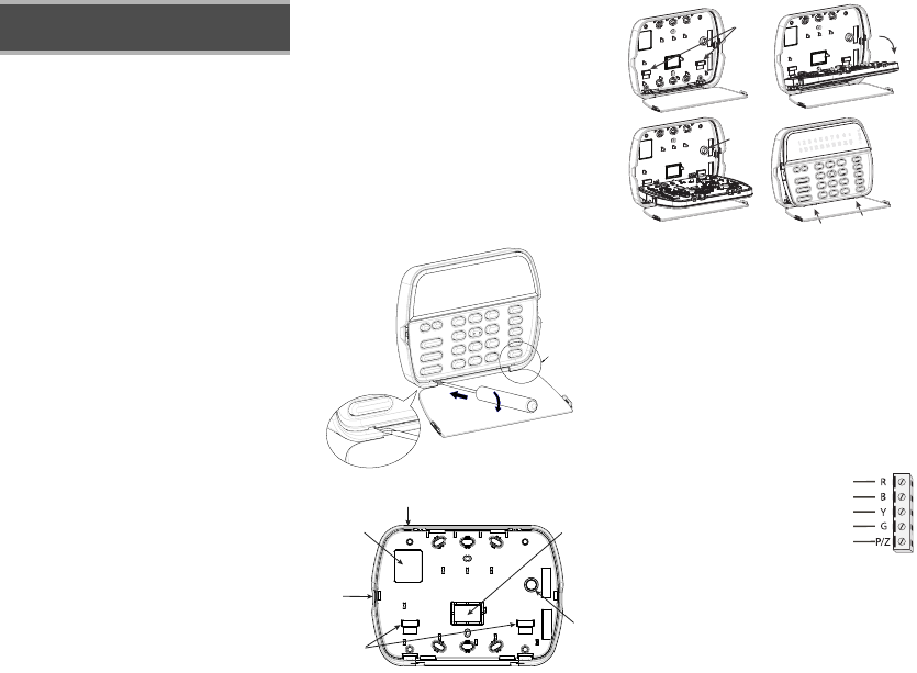
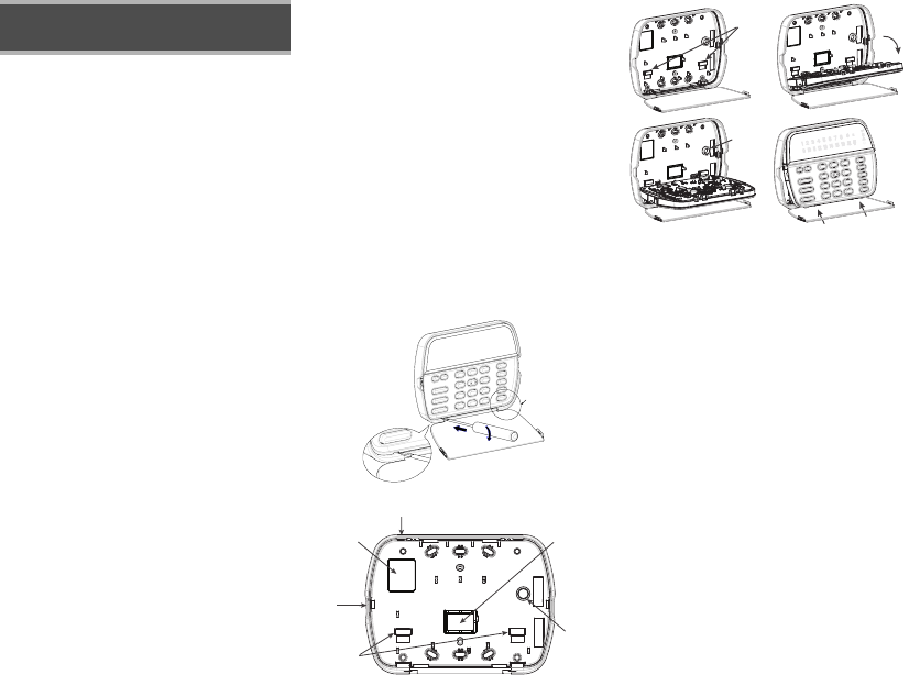
Disassemble Keypad
1. Insert a flat head screwdriver into the provided slot (first of two)
2. Move screwdriver toward the back plastic and lift as in the below
diagram. This will unhook one side of the front plastic.
3. Repeat step # 1 and 2 on the second provided slot to disconnect
the front plastic and allow access for wiring.
Mount and Wire Keypad
1. Secure Keypad to wall using mounting holes. Use all 4 screws provided
unless mounting on a single gang box.
2. Place keypad into hooks on the backplate and swing down to engage.
3. Run wire through wiring slot or knockouts. Connect Keybus and PGM/Zone
wiring to keypad. Place tamper switch into tamper hole on backplate.
4. Remove keypad from hooks. Place keypad into backplate, ensure the wire
is pushed back into the wall as much as possible. Route the wire inside
the keypad ensuring high components are avoided. Snap the front assem-
bly closed, ensuring that there is no pressure to the keypad from the wire
below.
NOTE: If any tension found between the front keypad assembly and wiring,
please open the keypad reroute the wire and close again. Repeat these
steps until the keypad is closed properly.
Wiring
1. Before wiring the unit, ensure that all power (AC transformer and battery)
is disconnected from the control panel.
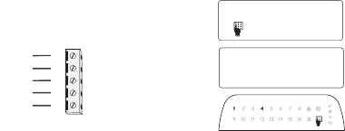
2. Connect the four Keybus wires from the con-
trol panel (red, black, yellow and green) to
the keypad terminals. Refer to diagram:
3. If programmed as an input, you can con-
nect a device - such as a door contact - to
the ‘P/Z’ terminal of the keypad. This elim-
inates the need to run wires back to the
control panel for the device. To connect the
zone, run one wire from the device to the ‘P/Z’ terminal and the other wire
from the device to the B (black) terminal. For powered devices, run the red
wire to the R (positive) terminal and the black wire to the B (negative)
terminal. When using end of line supervision, connect the zone according
to one of the configurations outlined in your system’s Installation Manual.
4. If the ‘P/Z’ terminal is programmed as an output, the output follows the
PGM programmed in Section [080]. A small relay, buzzer or other DC
English
Installation Instructions
•PC580 •PC585 •PC1555MX •PC1565
•PC1616 •PC1832 •PC1864 •PC5005
•PC5008 •PC5010 •PC5015 •PC5016
•PC5020
•One Power keypad •Keypad inner door labels
•Four mounting screws •1 tamper switch
•2 end-of-line resistors •Installation Instructions
1
2
3
Knock Out
Knock Out
Knock Out
Wiring Slot
Tamper
Hooks
Swing
to engage
Press to Snap
1. 2.
3. 4.
Ta m p e r
Hooks
RFK5501/5500
RED
BLK
YEL
GRN
To zone or
PGM output
operated device may be connected between the positive supply voltage
and the ‘P/Z’ terminal (maximum load is 50mA).
NOTE: For UL Residential Fire Installations use at least one additional DSC
compatible keypad in conjunction with an RFK5501/5500-433 keypad or
install the RFK5501/5500-433 keypads within 3 feet from the control unit
and mechanically protect the keybus wires
Applying Power
Once all wiring is complete, and the equipment is secured to the building
structure with at least two screws apply power to the control panel:
1. Connect the battery leads to the battery.
2. Connect the AC transformer.
For more information on control panel power specifications, see the control
panel Installation Manual.
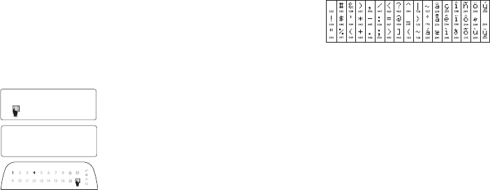
Programming the Keypad
There are several programming
options available for the keypad.
These are described below. Pro-
gramming the keypad is similar
to programming the rest of the
system. When you are in the key-
pad programming sections, the
keypad will display which
options are turned on along the
top of the display. To turn an
option on or off, press the num-
ber corresponding to the option
on the number pad. The numbers of the options that are currently turned
ON will be displayed. For example, if options 1 and 4 are on, the display
will look like diagram shown on the different keypad displays.
For information on programming the rest of your security system, please
refer to your system’s Installation Manual.
Broadcasting LCD Labels
All LCD programming is done per keypad. If more than one LCD keypad is
present on the system, labels programmed at one keypad can be broadcast
to all other LCD keypads. Perform the following procedure in order to broad-
cast labels:
Step 1 - Program one LCD keypad completely.
Step 2 - Make sure all LCD keypads are connected to the Keybus.
Step 3 - Enter keypad programming by pressing [4][8][Installer
Code][4], then enter section [998] at the keypad that was programmed.
The keypad will now broadcast all the information programmed to all the
other LCD keypads on the system.
Step 4 - When the keypad is finished press the [#] key to exit.
NOTE: LCD Label broadcast from this keypad is only compatible
with other RFK5501/5500 Keypads.
Language Programming
Hold (<>) keys for 2 seconds to enter language programming, scroll to
the desired language and Press [4] to select.
NOTE: If section [077] option 4 is OFF, language programming
can only be performed while in installers programming.
Enrolling the Keypad
The keypad will need to be assigned to a partition and slot if supervision or
keypad zones are being used. Keypad assignments and keypad option pro-
gramming must be done at each keypad individually.
The 1st digit of keypad assignment is used to determine partition assign-
ment (1 to 8). If partitioning is not used, enter [1]. For Global Keypads,
enter [0].
NOTE: LED and ICON keypads cannot be programmed as Global Keypads
The 2nd digit of keypad assignment is used to determine slot assignment
for keypad supervision. Each keypad will be assigned a different slot num-
ber from 1 to 8. RFK5501/5500 LCD keypads come defaulted in slot 8. If
LCD keypads are used one LCD keypad must remain in slot 8.
NOTE: The keypad enrolls as two modules:
Light 1 = keypad section
Light 17 = receiver section
NOTE: Deleting all wireless devices from the keypad or defaulting the key-
pad will cause a supervisory fault.
Enter the following at each keypad installed on the system:
1. Enter Installer Programming by pressing [4][8][Installer’s Code]
2. Press [000] for Keypad Programming
3. Press [0] for Partition and Slot Assignment
4. Enter the 1st digit (0 to 8 for partition assignment)
5. Enter the 2nd digit (1 to 8 for slot assignment supervision)
6. Press the [#] key twice to exit programming.
7. After assigning all keypads, perform a supervisory reset by entering
[4][8][Installer’s Code][902] and wait for 60 seconds.
8. Press the [#] key to exit programming after 60 seconds.
Programming Labels
1. Enter keypad programming by pressing [4][8][Installer Code][4]. Enter
the 3-digit section number for the label to be programmed.
2. Use the arrow keys (<>) to move the underline bar underneath the let-
ter to be changed.
3. Press the number keys [1] to [9] corresponding to the letter you require.
The first time you press the number the first letter will appear. Pressing the
number key again will display the next letter.
4. When the required letter or number is displayed use the arrow keys
(<>) to scroll to the next letter.
5. When you are finished programming the Zone Label, press the [4] key,
scroll to “Save,” then press [4].
6. Continue from Step 2 until all Labels are programmed.
ASCII Characters
Changing Brightness/Contrast
LCD Keypads
1. Press [4][6][Master code].
2. Use the [<][>] keys to scroll to either Brightness Control or Contrast Control.
3. Press [4] to select the setting you want to adjust.
4. a) ‘Brightness Control’: There are multiple backlighting levels. Use the [<][>]
keys to scroll to the desired level.
b) ‘Contrast Control’: There are 10 different display contrast levels. Use the
[<][>] keys to scroll to the desired contrast level.
5. To exit, press [#].
LED/ICON Keypads
1. Press [4][6][Master Code].
2. Use the [>] key to move through the 4 different backlighting levels.
3. The level is automatically saved when you press [#] to exit.
Changing the Buzzer Level
LCD Keypads
1. Press [4][6][Master Code].
2. Use the [<][>] keys to scroll to Buzzer Control.
3. There are 21 different levels, use the [<][>] keys to scroll to the desired level.
4. To exit, press [#].
LED/ICON Keypads
1. Press [4][6][Master Code].
2. Use the [<] key to move through the 21 different buzzer levels.
3. The level is automatically saved when you press [#] to exit.
Broadcasting Door Chime
All door chime programming is done per keypad. If more than one keypad is
present on the system, door chime programmed at one keypad can be broad-
cast to all other keypads. Perform the following procedure in order to broadcast
door chime:
Step 1 - Program one keypad completely.
Step 2 - Make sure all keypads are connected to the Keybus.
Step 3 - Enter keypad programming by pressing [4][8][Installer Code][4], then
enter section [994] at the keypad that was programmed. The keypad will
now broadcast all the door chime information programmed to all the
other keypads on the system.
Step 4 - When the keypad is finished press the [#] key to exit.
41
Toggle Option
1 _ _ 4 _ _ _ _
[1] - A, B, C, 1 [4] - J, K, L, 4 [7] - S, T, U, 7 [0] - Space
[2] - D, E, F, 2 [5] - M, N, O, 5 [8] - V, W, X, 8
[3] - G, H, I, 3 [6] - P, Q, R, 6 [9] - Y, Z, 9,0

Limited Warranty
Digital Security Controls warrants that for a period of 12 months from the date of purchase, the
product shall be free of defects in materials and workmanship under normal use and that in fulfil-
ment of any breach of such warranty, Digital Security Controls shall, at its option, repair or replace
the defective equipment upon return of the equipment to its repair depot. This warranty applies
only to defects in parts and workmanship and not to damage incurred in shipping or handling, or
damage due to causes beyond the control of Digital Security Controls such as lightning, excessive
voltage, mechanical shock, water damage, or damage arising out of abuse, alteration or improper
application of the equipment.
The foregoing warranty shall apply only to the original buyer, and is and shall be in lieu of any and
all other warranties, whether expressed or implied and of all other obligations or liabilities on the
part of Digital Security Controls. Digital Security Controls neither assumes responsibility for, nor
authorizes any other person purporting to act on its behalf to modify or to change this warranty, nor
to assume for it any other warranty or liability concerning this product.
In no event shall Digital Security Controls be liable for any direct, indirect or consequential dam-
ages, loss of anticipated profits, loss of time or any other losses incurred by the buyer in connec-
tion with the purchase, installation or operation or failure of this product.
Warning: Digital Security Controls recommends that the entire system be completely tested on a
regular basis. However, despite frequent testing, and due to, but not limited to, criminal tampering
or electrical disruption, it is possible for this product to fail to perform as expected.
Important Information:Changes or modifications not expressly approved by Digital Security Con-
trols could void the user’s authority to operate this equipment.
FCC Compliance Statement
Caution: Changes or modifications not expressly approved by Digital Security Controls could void
your authority to use this equipment.
This equipment generates and uses radio frequency energy and if not installed and used properly, in
strict accordance with the manufacturer’s instructions, may cause interference to radio and television
reception. It has been type tested and found to comply with the limits for Class B device in accor-
dance with the specifications in Subpart “B” of Part 15 of FCC Rules, which are designed to provide
reasonable protection against such interference in any residential installation. However, there is no
guarantee that interference will not occur in a particular installation. If this equipment does cause
interference to television or radio reception, which can be determined by turning the equipment off
and on, the user is encouraged to try to correct the interference by one or more of the following mea-
sures:
• Re-orient the receiving antenna
• Relocate the alarm control with respect to the receiver
• Move the alarm control away from the receiver
• Connect the alarm control into a different outlet so that alarm control and receiver are on different
circuits.
If necessary, the user should consult the dealer or an experienced radio/television technician for addi-
tional suggestions. The user may find the following booklet prepared by the FCC helpful: “How to
Identify and Resolve Radio/Television Interference Problems”. This booklet is available from the U.S.
Government Printing Office, Washington, D.C. 20402, Stock # 004-000-00345-4.
IMPORTANT - READ CAREFULLY: DSC Software purchased with or without Products and Components
is copyrighted and is purchased under the following license terms:
• This End-User License Agreement (“EULA”) is a legal agreement between
You
(the company,
individual or entity who acquired the Software and any related Hardware) and
Digital Security
Controls, a division of Tyco Safety Products Canada Ltd.
(“DSC”), the manufacturer of the
integrated security systems and the developer of the software and any related products or
components (“HARDWARE”) which You acquired.
• If the DSC software product (“SOFTWARE PRODUCT” or “SOFTWARE”) is intended to be
accompanied by HARDWARE, and is NOT accompanied by new HARDWARE, You may not
use, copy or install the SOFTWARE PRODUCT. The SOFTWARE PRODUCT includes computer
software, and may include associated media, printed materials, and “online” or electronic
documentation.
• Any software provided along with the SOFTWARE PRODUCT that is associated with a separate
end-user license agreement is licensed to You under the terms of that license agreement.
• By installing, copying, downloading, storing, accessing or otherwise using the SOFTWARE
PRODUCT, You agree unconditionally to be bound by the terms of this EULA, even if this EULA
is deemed to be a modification of any previous arrangement or contract. If You do not agree to
the terms of this EULA, DSC is unwilling to license the SOFTWARE PRODUCT to You, and You
have no right to use it.
SOFTWARE PRODUCT LICENSE
The SOFTWARE PRODUCT is protected by copyright laws and international copyright treaties, as
well as other intellectual property laws and treaties. The SOFTWARE PRODUCT is licensed, not
sold.
1.GRANT OF LICENSE This EULA grants You the following rights:
(a)
Software Installation and Use
- For each license You acquire, You may have only one copy
of the SOFTWARE PRODUCT installed.
(b)
Storage/Network Use
- The SOFTWARE PRODUCT may not be installed, accessed,
displayed, run, shared or used concurrently on or from different computers, including a
workstation, terminal or other digital electronic device (“Device”). In other words, if You
have several workstations, You will have to acquire a license for each workstation where the
SOFTWARE will be used.
(c)
Backup Copy
- You may make back-up copies of the SOFTWARE PRODUCT, but You may
only have one copy per license installed at any given time. You may use the back-up copy
solely for archival purposes. Except as expressly provided in this EULA, You may not
otherwise make copies of the SOFTWARE PRODUCT, including the printed materials
accompanying the SOFTWARE.
2. DESCRIPTION OF OTHER RIGHTS AND LIMITATIONS
(a)
Limitations on Reverse Engineering, Decompilation and Disassembly
- You may not reverse
engineer, decompile, or disassemble the SOFTWARE PRODUCT, except and only to the
extent that such activity is expressly permitted by applicable law notwithstanding this
limitation. You may not make any changes or modifications to the Software, without the
written permission of an officer of DSC. You may not remove any proprietary notices, marks
or labels from the Software Product. You shall institute reasonable measures to ensure
compliance with the terms and conditions of this EULA.
(b)
Separation of Components
- The SOFTWARE PRODUCT is licensed as a single product. Its
component parts may not be separated for use on more than one HARDWARE unit.
(c)
Single INTEGRATED PRODUCT
- If You acquired this SOFTWARE with HARDWARE, then the
SOFTWARE PRODUCT is licensed with the HARDWARE as a single integrated product. In
this case, the SOFTWARE PRODUCT may only be used with the HARDWARE as set forth in
this EULA.
(d)
Rental
- You may not rent, lease or lend the SOFTWARE PRODUCT. You may not make it
available to others or post it on a server or web site.
(e)
Software Product Transfer
- You may transfer all of Your rights under this EULA only as part
of a permanent sale or transfer of the HARDWARE, provided You retain no copies, You
transfer all of the SOFTWARE PRODUCT (including all component parts, the media and
printed materials, any upgrades and this EULA), and provided the recipient agrees to the
terms of this EULA. If the SOFTWARE PRODUCT is an upgrade, any transfer must also
include all prior versions of the SOFTWARE PRODUCT.
(f)
Termination
- Without prejudice to any other rights, DSC may terminate this EULA
if You fail to comply with the terms and conditions of this EULA. In such event, You
must destroy all copies of the SOFTWARE PRODUCT and all of its component
parts.
(g)
Trademarks
- This EULA does not grant You any rights in connection with any
trademarks or service marks of DSC or its suppliers.
3. COPYRIGHT
- All title and intellectual property rights in and to the SOFTWARE
PRODUCT (including but not limited to any images, photographs, and text incorporated
into the SOFTWARE PRODUCT), the accompanying printed materials, and any copies of
the SOFTWARE PRODUCT, are owned by DSC or its suppliers. You may not copy the
printed materials accompanying the SOFTWARE PRODUCT. All title and intellectual
property rights in and to the content which may be accessed through use of the
SOFTWARE PRODUCT are the property of the respective content owner and may be
protected by applicable copyright or other intellectual property laws and treaties. This
EULA grants You no rights to use such content. All rights not expressly granted under
this EULA are reserved by DSC and its suppliers.
4. EXPORT RESTRICTIONS
- You agree that You will not export or re-export the
SOFTWARE PRODUCT to any country, person, or entity subject to Canadian export
restrictions.
5. CHOICE OF LAW
-
This Software License Agreement is governed by the laws of
the Province of Ontario, Canada.
6. ARBITRATION
-
All disputes arising in connection with this Agreement shall be
determined by final and binding arbitration in accordance with the Arbitration Act, and
the parties agree to be bound by the arbitrator’s decision. The place of arbitration shall
be Toronto, Canada, and the language of the arbitration shall be English.
7. LIMITED WARRANTY
(a) NO WARRANTY
- DSC PROVIDES THE SOFTWARE “AS IS” WITHOUT WARRANTY. DSC
DOES NOT WARRANT THAT THE SOFTWARE WILL MEET YOUR REQUIREMENTS OR
THAT OPERATION OF THE SOFTWARE WILL BE UNINTERRUPTED OR ERROR-FREE.
(b) CHANGES IN OPERATING ENVIRONMENT -
DSC shall not be responsible for
problems caused by changes in the operating characteristics of the HARDWARE,
or for problems in the interaction of the SOFTWARE PRODUCT with non-DSC-
SOFTWARE or HARDWARE PRODUCTS.
(c) LIMITATION OF LIABILITY; WARRANTY REFLECTS ALLOCATION OF RISK
- IN ANY
EVENT, IF ANY STATUTE IMPLIES WARRANTIES OR CONDITIONS NOT STATED IN
THIS LICENSE AGREEMENT, DSC’S ENTIRE LIABILITY UNDER ANY PROVISION
OF THIS LICENSE AGREEMENT SHALL BE LIMITED TO THE GREATER OF THE
AMOUNT ACTUALLY PAID BY YOU TO LICENSE THE SOFTWARE PRODUCT AND
FIVE CANADIAN DOLLARS (CAD$5.00). BECAUSE SOME JURISDICTIONS DO
NOT ALLOW THE EXCLUSION OR LIMITATION OF LIABILITY FOR
CONSEQUENTIAL OR INCIDENTAL DAMAGES, THE ABOVE LIMITATION MAY NOT
APPLY TO YOU.
(d) DISCLAIMER OF WARRANTIES
- THIS WARRANTY CONTAINS THE ENTIRE
WARRANTY AND SHALL BE IN LIEU OF ANY AND ALL OTHER WARRANTIES,
WHETHER EXPRESSED OR IMPLIED (INCLUDING ALL IMPLIED WARRANTIES OF
MERCHANTABILITY OR FITNESS FOR A PARTICULAR PURPOSE) AND OF ALL
OTHER OBLIGATIONS OR LIABILITIES ON THE PART OF DSC. DSC MAKES NO
OTHER WARRANTIES. DSC NEITHER ASSUMES NOR AUTHORIZES ANY OTHER
PERSON PURPORTING TO ACT ON ITS BEHALF TO MODIFY OR TO CHANGE THIS
WARRANTY, NOR TO ASSUME FOR IT ANY OTHER WARRANTY OR LIABILITY
CONCERNING THIS SOFTWARE PRODUCT.
(e) EXCLUSIVE REMEDY AND LIMITATION OF WARRANTY -
UNDER NO CIRCUMSTANCES
SHALL DSC BE LIABLE FOR ANY SPECIAL, INCIDENTAL, CONSEQUENTIAL OR INDIRECT
DAMAGES BASED UPON BREACH OF WARRANTY, BREACH OF CONTRACT, NEGLIGENCE,
STRICT LIABILITY, OR ANY OTHER LEGAL THEORY. SUCH DAMAGES INCLUDE, BUT ARE
NOT LIMITED TO, LOSS OF PROFITS, LOSS OF THE SOFTWARE PRODUCT OR ANY
ASSOCIATED EQUIPMENT, COST OF CAPITAL, COST OF SUBSTITUTE OR REPLACEMENT
EQUIPMENT, FACILITIES OR SERVICES, DOWN TIME, PURCHASERS TIME, THE CLAIMS
OF THIRD PARTIES, INCLUDING CUSTOMERS, AND INJURY TO PROPERTY.
WARNING:
DSC recommends that the entire system be completely tested on a
regular basis. However, despite frequent testing, and due to, but not limited to,
criminal tampering or electrical disruption, it is possible for this SOFTWARE
PRODUCT to fail to perform as expected.
©2009 Digital Security Controls, Toronto, Canada • www.dsc.com Printed in Canada

Keypad Enrollment
Enter keypad programming by pressing [4][8][Installer’s Code][000].
[0] Partition / Slot Assignment
[1]-[5] Function Key Assignment
Keypad Function Keys
Refer to your system installation manual for a complete list of all function key options available for your system.
Keypad Programming
Enter keypad programming by pressing [4][8][Installer Code][4]
[001]-[064] Zone Label 1 to 64 (PK5500\RFK5500 Only)
ex. For Zone 1 enter section [001], for Zone 2 enter section [002] etc. Default: “Zone 1” - “Zone 64”
[065] Fire Alarm Label (28 Characters)
Default:“Fire Zone”
[066] Fail to Arm Event Message
Default: “System Has Failed to Arm”
[067] Alarm When Armed Event Message
Default: “Alarm Occurred While Armed < >”
[071] First User Display Mask
[072] Second User Display Mask
[073] Download LCD Message Duration
Default: 003 I_____I_____I_____I (Valid entries are 000-255), 000=Unlimited Message Disp.This
number represents the number of times the Downloaded message is cleared by pressing any key while the
message is up after timeout).
Digit Option Valid Range Default
1st Partition Assignment (0=Global Keypad) 0 to 8 1 I_____I
2nd Slot Assignment 1 to 8 LED,ICON=1/LCD=8 I_____I
Function Key Button Valid Range Default Function
[1] Function Key 1 Assignment 00 to 32 03 Stay Arm I_____I_____I
[2] Function Key 2 Assignment 00 to 32 04 Away Arm I_____I_____I
[3] Function Key 3 Assignment 00 to 32 06 Chime On/Off I_____I_____I
[4] Function Key 4 Assignment 00 to 32 14 Sensor Reset I_____I_____I
[5] Function Key 5 Assignment 00 to 32 16 Quick Exit I_____I_____I
[00] - Null [08] - Bypass Mode [16] - Quick Exit [26] - Time & Date Program
[01] - Partition 1 Select [09] - Trouble Display [17] - Activate Stay/Away [27] - Partition 3 Select
[02] - Partition 2 Select [10] - Alarm Memory [18] - *Global Away Arm [28] - Partition 4 Select
[03] - Stay Arm [11] - User Programming [19] - Command Output 3 [29] - Partition 5 Select
[04] - Away Arm [12] - User Functions [21] - Command Output 4 [30] - Partition 6 Select
[05] - No Entry Arm [13] - Command Output 1 [22] - *Global Disarming [31] - Partition 7 Select
[06] - Chime On/Off [14] - Command Output 2 [23] - Bypass Recall [32] - Partition 8 Select
[07] - System Test [15] - *Global Stay Arm [24] - Bypass Group Recall [33] - Local PGM Activate
*Available only on the PC1616/PC1832/PC1864 version 4.2 or higher.
Section Zone Label
[001] to [064] 1 to 64 I_____I_____I_____I_____I_____I_____I_____I_____I_____I_____I_____I_____I_____I_____I
I_____I_____I_____I_____I_____I_____I_____I_____I_____I_____I_____I_____I_____I_____I
[065] I_____I_____I_____I_____I_____I_____I_____I_____I_____I_____I_____I_____I_____I_____I
I_____I_____I_____I_____I_____I_____I_____I_____I_____I_____I_____I_____I_____I_____I
[066] I_____I_____I_____I_____I_____I_____I_____I_____I_____I_____I_____I_____I_____I_____I_____I_____I
I_____I_____I_____I_____I_____I_____I_____I_____I_____I_____I_____I_____I_____I_____I_____I_____I
[067] I_____I_____I_____I_____I_____I_____I_____I_____I_____I_____I_____I_____I_____I_____I_____I_____I
I_____I_____I_____I_____I_____I_____I_____I_____I_____I_____I_____I_____I_____I_____I_____I_____I
Default Option ON OFF
ON I____I 1 Hold [P]anic Key prompt ON Hold [P]anic Key prompt OFF
ON I____I 2 Auto-arm Control/Time prompt ON Auto-arm Control/Time prompt OFF
ON I____I 3 Quick Arm prompt ON Quick Arm prompt OFF
ON I____I 4 Interior Arm prompt ON Interior Arm prompt OFF
OFF I____I 5 Quick Exit prompt ON Quick Exit prompt OFF
OFF I____I 6 Thermostat Control prompt ON Thermostat Control prompt OFF
OFF I____I 7 ACK All Trouble Prompt ON ACK All Trouble Prompt OFF
OFF I____I 8 Music Input prompt ON Music Input prompt OFF
Default Option ON OFF
ON I____I 1 User-initiated Call-up prompt ON User-initiated Call-up prompt OFF
OFF I____I 2For Future Use
OFF I____I 3 Walk Test prompt ON Walk Test prompt OFF
ON I____I 4 Command Output#1 prompt ON Command Output#1 prompt OFF
ON I____I 5 Command Output#2 prompt ON Command Output#2 prompt OFF
OFF I____I 6 Command Output#3 prompt ON Command Output#3 prompt OFF
OFF I____I 7 Command Output#4 prompt ON Command Output#4 prompt OFF
OFF I____I 8For Future Use
[074] Key Options
[076] First Keypad Options
[077] Second Keypad Options
[080] PGM Terminal 1
Default: 01 I_______I _______I 1-14 Follow PGM Output Number, 15 Local PGM Pulse , 16 Local PGM Toggle
[082] Local PGM Output Pulse Activation Time
Default: 00 I_______I _______I Minutes (Valid Range 00-99)
Default: 05 I_______I _______I Seconds (Valid Range 00-99)
[101]-[108] Partition Labels (PK5500\RFK5500 Only)
ex. For Partition 1 enter section [101], for Partition 2 enter section [102] etc.
NOTE: Partition 1 Label is also used as the System Label
[120]-[151] Command Output Labels
Default: “Command_O/P_1” - “Command_O/P_4”
[201]-[264] Door Chime Sound Programming
You can program the keypad to make up to four different door chime sounds for individual zones.
ex. For Zone 1 enter section [201], for Zone 2 enter section [202] etc.
[994][Q] Initiate Global Keypad Chime Broadcast
[995][4] Reset Keypad Options to Factory Default
[996][4] Label Default
[997] View Software Version
[998][4] Initiate Global Label Broadcast
[999][4] Reset Keypad EEPROM to Factory Defaults
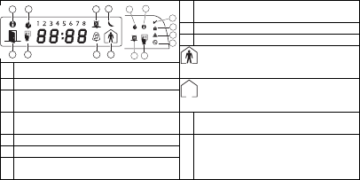
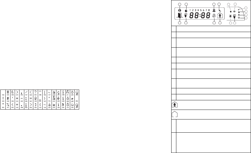
Keypad Display Symbols
Default Option ON OFF
ON I____I 1 [F]ire Key Enabled [F]ire Key Disabled
ON I____I 2 [A]uxiliary Key Enabled [A]uxiliary Key Disabled
ON I____I 3 [P]anic Key Enabled [P]anic Key Disabled
OFF I____I 4-8 For Future Use
Default Option ON OFF
ON I____I 1 Display Code when Programming Display “Xs” when Programming
ON I____I 2 Local Clock Display ON Local Clock Display OFF
OFF I____I 3 Local Clock Displays 24-hr Time Local Clock Displays AM/PM
ON I____I 4 Auto Alarm Memory Scroll Enabled Auto Alarm Memory Scroll Disabled
OFF I____I 5 Local Display of Temperature ON Local Display of Temperature OFF
ON I____I 6 Bypass Options prompt ON Bypass Options prompt OFF
OFF I____I 7For Future Use
OFF I____I 8 Auto-Scroll Open Zones ON Auto-Scroll Open Zones OFF
Default Option ON OFF
ON I____I 1 Chime Enabled for Zone Openings Chime Disabled for Zone Openings
ON I____I 2 Chime Enabled for Zone Closings Chime Disabled for Zone Closings
OFF I____I 3 5th Terminal is Keypad PGM Output 5th Terminal is Keypad Zone Input
ON I____I 4 Language Selection Enabled Language Selection Disabled
OFF I____I 5 Power LED Enabled Power LED Disabled
ON I____I 6 Power LED indicates AC present Power LED indicates AC absent
ON I____I 7 Alarms always Displayed When Armed Alarms not Displayed When Armed
OFF I____I 8 Low Temperature Warning Enabled Low Temperature Warning Disabled
Section Partition Label
[101] to [108] 1 to 8 I_____I_____I_____I_____I_____I_____I_____I_____I_____I_____I_____I_____I_____I_____I
I_____I_____I_____I_____I_____I_____I_____I_____I_____I_____I_____I_____I_____I_____I
For Partition 1 Command O/P 1 to 4 enter [120] to [123] For Partition 5 Command O/P 1 to 4 enter [136] to [139]
For Partition 2 Command O/P 1 to 4 enter [124] to [127] For Partition 6 Command O/P 1 to 4 enter [140] to [143]
For Partition 3 Command O/P 1 to 4 enter [128] to [131] For Partition 7 Command O/P 1 to 4 enter [144] to [147]
For Partition 4 Command O/P 1 to 4 enter [132] to [135] For Partition 8 Command O/P 1 to 4 enter [148] to [151]
Section Part Cmd.
Output Label
[120]-[151]1to8 1to4 I_____I_____I_____I_____I_____I_____I_____I_____I_____I_____I_____I_____I_____I_____I
I_____I_____I_____I_____I_____I_____I_____I_____I_____I_____I_____I_____I_____I_____I
Default Option ON OFF
ON I____I 1 6 Beeps Disabled
OFF I____I 2 “Bing-Bing” Sound Disabled
OFF I____I 3 “Ding-Dong” Sound Disabled
OFF I____I 4Alarm Tone Disabled
OFF I____I 5-8 For Future Use
8Bypass – Indicates that there are zones automatically or
manually bypassed.
9For Future Use
10 Arm Mode – Indicates the mode the panel is armed in.
Stay – Indicates that the panel is armed in the Stay
Mode. It will turn on at the beginning of the Exit
Delay
1Fire – Indicates that there are fire alarms in memory.
2Memory – Indicates that there are alarms in memory. Away – Indicates that the panel is armed in the Away
Mode. It will turn on at the beginning of the Exit
Delay
3Ready Light (green) – If the Ready light is on, the system
is ready for arming.
4Armed Light (red) – If the Armed light is on, the system
has been armed successfully. 11 Chime – This icon turns on when Door Chime is enabled on
the system and will turn off when Door Chime is disabled.
5System Trouble – Indicates that a system trouble is active.
12 Open – When zones are opened, this icon will turn on, and
7 segment displays 1 and 2 will scroll through the open
zones.
6AC – Indicates that AC is present at the main panel.
7Program – Indicates that the system is in Installer’s Pro-
gramming, or the keypad is busy.
12
3
4
5
6
7
8
12 9
10
11
12 7
8

Wireless Integration
Compatible Wireless Devices
The RFK5501/5500 can receive signals from the following devices:
Downloading
The RFK5501/5500 has an integrated wireless receiver. When down-
loading to this keypad, please select the PC5132-433 v5.2 file.
DLS2002 must be used in order to have the capability of downloading
to this keypad.
Testing Wireless Devices
1. Temporarily put the wireless devices in the places you want to
mount them.
2. At a system keypad, enter [4][8][Installer Code].
3. Enter programming section [904], then enter the 2-digit zone
number.
NOTE: If global placement test is enabled (Section [90], option 8
ON) enter [01] to test all zones.
4. Activate the device being tested until a result is displayed on the
keypad or sounded by the keypad or bell
While in placement test the Ready and Armed LEDs are used to indi-
cate the reception of a valid signal from a wireless device. The Green
(Ready) LED indicates that a transmission was received from a device
that is enrolled on the system. The Red (Armed) LED indicates that a
transmission was received from a device that is not enrolled on the
system. The corresponding LED will flash once per transmission.
Activate the device until you get 3 good results in a row. Wait 10 sec-
onds between each test on the same device. You may mount wireless
devices where results were good.
Devices indicating a bad result must be moved to another location.
You may only have to move the device a few inches to correct a bad
result.
NOTE: Do not mount any device where a “bad” test result was
indicated.
Testing Portable Device Reception
To test portable devices (e.g., WS4938, WS4939) press the button(s)
at several different points in the installation, to confirm the coverage
area. If these devices do not operate from all points in the installation,
you will need to move the RFK5501/5500.
Replacing Wireless Device
Batteries
1. Remove the cover of the device from its backplate. This creates a
tamper condition on the zone.
2. Refer to the battery installation instructions on the Installation
Sheet of each component. Be sure to note the proper orientation of
the batteries as you install them.
3. When the fresh batteries are in place, re-attach the cover to the
backplate. The tamper is restored and the zone sends a battery
trouble restoral signal to the receiver. The battery trouble is now
clear and the device should function normally.
NOTE: When batteries in one device need to be replaced, the bat-
teries in all devices should be replaced at the same time.
Troubleshooting
1. When I enter the 2-digit zone number when adding a wireless
device, the keypad gives me a long beep.
• You cannot enter ESNs unless the keypad is properly connected to the
Keybus.
2. I have entered the ESN for the device but when I violate the device,
the zone does not show open on the keypad.
Check the following:
• Ensure the ESN has been entered correctly
• Ensure that the zone is enabled for the partition (if partition program-
ming is used).
• Ensure that the wireless zone is not assigned to a zone used by
PC5108 modules, an on-board zone or a keypad zone.
• Ensure that the zone is programmed for something other than “Null
Operation” and that the wireless zone attribute is turned on.
3. When I try a module placement test I get no result or “Bad” results.
Check the following:
• Verify that you are testing the correct zone
• Verify that the correct ESN was entered when the device was enrolled
• Verify that the device is in range of the keypad. Try testing the device
in the same room as the receiver.
• Confirm that the keypad is properly connected to the Keybus.
• Check that you are testing the zone correctly. Refer to the instructions
that came with the zone.
• Check that the batteries are working and installed correctly.
• Look for large metal objects that may be preventing the signal from
reaching the keypad.
• The device must be located where consistent “Good” results are
obtained. If several devices show “Bad” results, or if panic pendants
and wireless keys operate inconsistently, move the receiver.
4. The LED on the motion detector does not turn on when I walk in
front of the unit.
• The LED on the motion detector is for walk test purposes only. See
your WLS904-433/WLS904P(L)-433 Instruction Sheet for walk test
instructions.
Notes:
•WLS914-433 Pet Immune PIR •WLS912L-433 Glass Break Detector
•WS4965 Tri-Zone Contact •WLS904(P)L-433 Pet Immune PIR
•WS4938 Panic Button •WLS925L-433 Mini Door/Window Contact
•WS4916 Smoke Detector •WS49X9 Wireless Keys
Result LED/ICON Keypad LCD Keypad Bell/Buzzer
Good Light 1 ON Steady Good 1 Beep/Squawk
Bad Light 3 ON Steady Bad 3 Beeps/Squawks
Wireless Programming
Enter Wireless programming by pressing [4][8][Installer’s Code][804]
[01]-[32] Wireless Device Serial Number Zone Serial Numbers Default = 000000
[41]-[56] Wireless Key Serial Number Wireless Key Serial Numbers Default = 000000
[61]-[76] Wireless Function Key Options
Keypad Function Keys
Please see your system installation manual for a complete list of all the function key options available for your system.
[77] Wireless Keys (1-16) Partition Assignments Default = 01
[81] Wireless supervisory Window
Default: [NA] 96 = 24 hours / [EU] 10 =2.5 hours I_____I_____I
The window is programmed in 15 minute increments. Valid entries are 10 to 96, equal to 2.5 to 24 hours.
[82]-[85] Zone Device Supervision Options
[90] Other Options
NOTE: For UL Listed installations, the RF Jam detect feature must be enabled.
NOTE: For DD243 installations, the RF delinquency feature should be enabled.
NOTE: Supervision must be enabled for RF Delinquency.
[93] RF Jam Detect Zone
Default: 00 I_____I_____I Valid entries = 01 - 32, 00 = No RF Jam tone selected.
Select an unused zone that will be set to the tamper state when a jamming signal is detected.
[01] Zone 1 I_____I_____I_____I_____I_____I_____I [17] Zone 17 I_____I_____I_____I_____I_____I_____I
[02] Zone 2 I_____I_____I_____I_____I_____I_____I [18] Zone 18 I_____I_____I_____I_____I_____I_____I
[03] Zone 3 I_____I_____I_____I_____I_____I_____I [19] Zone 19 I_____I_____I_____I_____I_____I_____I
[04] Zone 4 I_____I_____I_____I_____I_____I_____I [20] Zone 20 I_____I_____I_____I_____I_____I_____I
[05] Zone 5 I_____I_____I_____I_____I_____I_____I [21] Zone 21 I_____I_____I_____I_____I_____I_____I
[06] Zone 6 I_____I_____I_____I_____I_____I_____I [22] Zone 22 I_____I_____I_____I_____I_____I_____I
[07] Zone 7 I_____I_____I_____I_____I_____I_____I [23] Zone 23 I_____I_____I_____I_____I_____I_____I
[08] Zone 8 I_____I_____I_____I_____I_____I_____I [24] Zone 24 I_____I_____I_____I_____I_____I_____I
[09] Zone 9 I_____I_____I_____I_____I_____I_____I [25] Zone 25 I_____I_____I_____I_____I_____I_____I
[10] Zone 10 I_____I_____I_____I_____I_____I_____I [26] Zone 26 I_____I_____I_____I_____I_____I_____I
[11] Zone 11 I_____I_____I_____I_____I_____I_____I [27] Zone 27 I_____I_____I_____I_____I_____I_____I
[12] Zone 12 I_____I_____I_____I_____I_____I_____I [28] Zone 28 I_____I_____I_____I_____I_____I_____I
[13] Zone 13 I_____I_____I_____I_____I_____I_____I [29] Zone 29 I_____I_____I_____I_____I_____I_____I
[14] Zone 14 I_____I_____I_____I_____I_____I_____I [30] Zone 30 I_____I_____I_____I_____I_____I_____I
[15] Zone 15 I_____I_____I_____I_____I_____I_____I [31] Zone 31 I_____I_____I_____I_____I_____I_____I
[16] Zone 16 I_____I_____I_____I_____I_____I_____I [32] Zone 32 I_____I_____I_____I_____I_____I_____I
[41] Key 1 I_____I_____I_____I_____I_____I_____I [49] Key 9 I_____I_____I_____I_____I_____I_____I
[42] Key 2 I_____I_____I_____I_____I_____I_____I [50] Key 10 I_____I_____I_____I_____I_____I_____I
[43] Key 3 I_____I_____I_____I_____I_____I_____I [51] Key 11 I_____I_____I_____I_____I_____I_____I
[44] Key 4 I_____I_____I_____I_____I_____I_____I [52] Key 12 I_____I_____I_____I_____I_____I_____I
[45] Key 5 I_____I_____I_____I_____I_____I_____I [53] Key 13 I_____I_____I_____I_____I_____I_____I
[46] Key 6 I_____I_____I_____I_____I_____I_____I [54] Key 14 I_____I_____I_____I_____I_____I_____I
[47] Key 7 I_____I_____I_____I_____I_____I_____I [55] Key 15 I_____I_____I_____I_____I_____I_____I
[48] Key 8 I_____I_____I_____I_____I_____I_____I [56] Key 16 I_____I_____I_____I_____I_____I_____I
Function 1
Default 03
Function 2
Default 04
Function 3
Default 27
Function 4
Default 30
Function 1
Default 03
Function 2
Default 04
Function 3
Default 27
Function 4
Default 30
[61] Key 1 I_____I_____I I_____I_____I I_____I_____I I_____I_____I [69] Key 9 I_____I_____I I_____I_____I I_____I_____I I_____I_____I
[62] Key 2 I_____I_____I I_____I_____I I_____I_____I I_____I_____I [70] Key 10 I_____I_____I I_____I_____I I_____I_____I I_____I_____I
[63] Key 3 I_____I_____I I_____I_____I I_____I_____I I_____I_____I [71] Key 11 I_____I_____I I_____I_____I I_____I_____I I_____I_____I
[64] Key 4 I_____I_____I I_____I_____I I_____I_____I I_____I_____I [72] Key 12 I_____I_____I I_____I_____I I_____I_____I I_____I_____I
[65] Key 5 I_____I_____I I_____I_____I I_____I_____I I_____I_____I [73] Key 13 I_____I_____I I_____I_____I I_____I_____I I_____I_____I
[66] Key 6 I_____I_____I I_____I_____I I_____I_____I I_____I_____I [74] Key 14 I_____I_____I I_____I_____I I_____I_____I I_____I_____I
[67] Key 7 I_____I_____I I_____I_____I I_____I_____I I_____I_____I [75] Key 15 I_____I_____I I_____I_____I I_____I_____I I_____I_____I
[68] Key 8 I_____I_____I I_____I_____I I_____I_____I I_____I_____I [76] Key 16 I_____I_____I I_____I_____I I_____I_____I I_____I_____I
[00] - Null [07] - System Test [17] - Activate Stay/Away [27] - Disarm
[03] - Stay Arm [13] - Command Output 1 [18] - Global Away Arm [28] - Fire Alarm
[04] - Away Arm [14] - Command Output 2 [19] - Command Output 3 [29] - Auxiliary Alarm
[05] - No Entry Arm [15] - Global Stay Arm [21] - Command Output 4 [30] - Panic Alarm
[06] - Chime On/Off [16] - Quick Exit [22] - Global Disarm [31] - Local PGM Activate
NOTE: Wireless keys must have an access code for global arm/disarm function.
Key 1 I_____I_____I Key 5 I_____I_____I Key 9 I_____I_____I Key 13 I_____I_____I
Key 2 I_____I_____I Key 6 I_____I_____I Key 10 I_____I_____I Key 14 I_____I_____I
Key 3 I_____I_____I Key 7 I_____I_____I Key 11 I_____I_____I Key 15 I_____I_____I
Key 4 I_____I_____I Key 8 I_____I_____I Key 12 I_____I_____I Key 16 I_____I_____I
Default ON [82]
Zone
Supervision
ON/OFF
[83]
Zone
Supervision
ON/OFF
[84]
Zone
Supervision
ON/OFF
[85]
Zone
Supervision
ON/OFF
Option 1 1 I_____I 9I_____I 17 I_____I 25 I_____I
Option 2 2 I_____I 10 I_____I 18 I_____I 26 I_____I
Option 3 3 I_____I 11 I_____I 19 I_____I 27 I_____I
Option 4 4 I_____I 12 I_____I 20 I_____I 28 I_____I
Option 5 5 I_____I 13 I_____I 21 I_____I 29 I_____I
Option 6 6 I_____I 14 I_____I 22 I_____I 30 I_____I
Option 7 7 I_____I 15 I_____I 23 I_____I 31 I_____I
Option 8 8 I_____I 16 I_____I 24 I_____I 32 I_____I
NA Default EU Default Option ON OFF
OFF OFF I____I 1,2,4 For Future Use
ON OFF I____I 3 Wall Tamper Disabled Wall Tamper Enabled
ON OFF I____I 5 RF Delinquency Disabled RF Delinquency Enabled
OFF OFF I____I 6For Future Use
ON OFF I____I 7 RF Jam Detect Disabled RF Jam Detect Enabled
OFF OFF I____I 8 Global Placement Test Individual Placement Test
Los teclados RFK5501/5500 pueden utilizarse en sistemas de seguri-
dad que contengan un máximo de 64 zonas. Estos teclados son com-
patibles con las últimas versions de los siguientes sistemas DSC :
Los teclados RFK5501/5500 combinan un receptor inalámbrico con el
respectivo teclado.
Especificaciones
• Intervalo de temperatura: de -10°C a +55°C (de 14°F a 131°F), Inter-
valo de temperatura para UL/ULC: 0°C a +49°C (32°F a 120°F)
• Humedad (máx): 93% de humedad relativa
• Grado de protección del envoltorio de plástico: IP30, IK04
• Tensión nominal: 12 VCC nominal
• Se conecta a un panel de control a través de un Keybus de 4 cables
• 1 teclado para entrada de zona/salida PGM*
• Consumo de corriente: 50 mA (espera) / 125 mA (máximo)
• Consumo de corriente: 75 mA (espera) / 135 mA (máximo)
• Montaje en la pared - violación
• 5 teclas de función programables
• Preparado (LED verde), Armado (LED rojo), Problema (LED amarillo), CA
(LED verde)
• Sensor de baja temperatura
• Frecuencia 433,92 MHz
• Hasta 32 zonas inalámbricas
* NOTA: Esta zona no debe programarse como tipo lncendio o tipo 24h
Desembalaje
El paquete del teclado de potencia contiene los siguientes elementos:
Prueba de localización
El RFK5501/5500 funciona mejor en lugares donde la interferencia
de RF es mínima. Para conseguir la ubicación mas óptima para el
teclado, ejecute la siguiente prueba de localización:
Paso 1- Conecte temporalmente los cables del keybus al teclado (con-
sulte las instrucciones de cableado).
Paso 2- Sostenga el teclado en el lugar en el que desea montarlo.
Paso 3- Ingrese al modo de programación del teclado presionando
[4][8][Código de Instalador], después ingrese a la sección [904]
Paso 4- Si el LED amarillo de Fallo del Sistema está encendido, los
niveles de interferencia son altos y se debe encontrar otro lugar para el
montaje del teclado. Si el LED está iluminado de manera intermitente,
la interferencia es baja y el lugar de montaje es bueno.
Montaje
Deberá montarse el teclado en un lugar accesible para los puntos des-
ignados de entrada y salida. Una vez seleccionada una ubicación seca
y segura, lleve a cabo los siguientes pasos para montar el teclado.
Desmontaje del teclado
1. Introduzca un destornillador de punta plana en la ranura inferior
(primera de dos).
2. Mueva el destornillador en la parte trasera tal y como muestra el
diagrama. Esto libera uno de los lados de la parte frontal.
3. Repita los pasos 1 y 2 en la segunda ranura para liberar totalmente
la parte frontal y permitir el acceso a las conexiones
Montaje e cableado del teclado
1. Fije el teclado en la pared utilizando perforaciones de montaje. Utilice los
cuatro tornillos proveidos, a menos que el montaje sea hecho en una sola
caja de acoplaje.
2. Coloque el teclado en los ganchos de la placa de apoyo y gírelo hacia
abajo para encajar.
3. Pase el cable por la ranura de cableado o perforaciones de salida. Conecte
los cables de Keybus y PGM/Zona al teclado. Coloque el interruptor de vio-
lación en la perforación de violación de la placa de apoyo.
4. Remova el teclado de los ganchos. Coloque el teclado en la placa de
apoyo, certifíquese de que el cable sea empujado hacia la pared lo máxi-
mo posible. Pase el cable por dentro del teclado, certifíquese que los com-
ponentes de arriba sean evitados. Cierre el conjunto frontal, garantizando
que no haya presión del cable abajo sobre el teclado.
NOTA: Si fuere detectada cualquier tensión entre el conjunto del teclado
frontal y el cableado, abra el teclado, repase el cable y cierre lo nueva-
mente. Repita esos procedimientos hasta que el teclado esté cerrado ade-
cuadamente.
Español
Instrucciones de instalación
•PC580 •PC585 •PC1555MX •PC1565
•PC1616 •PC1832 •PC1864 •PC5005
•PC5008 •PC5010 •PC5015 •PC5016
•PC5020
•Un teclado de potencia •Etiquetas de la puerta interior del teclado
•Cuatro tornillos de montaje •Un interruptor contra sabotajes
•Dos resistencias de fin de línea •Instrucciones de instalación
1
2
3
Orificio de salida
Orificio de
salida
Orificio de
salida
ranura de
cableado
violación
ganchos
gire hacia
encajar
presione para fijar
1. 2.
3. 4.
violación
ganchos
Cableado
1. 1. Antes de realizar el cableado de la unidad, asegúrese de que la
alimentación (transformador de CA y batería) está desconectada del
panel de control.
2. Conecte los cuatro cables del Keybus
desde el panel de control (rojo, negro,
amarillo y verde) a los bornes del
teclado. Consulte el diagrama:
3. Si va a ser programado como una
entrada, puede conectar un dispositivo
(por ejemplo, un contacto de puerta) al
borne ‘P/Z’ del teclado. De esta manera se elimina la necesidad de
llevar cables de vuelta al panel de control para el dispositivo. Para
conectar la zona, lleve un cable desde el dispositivo al borne ‘P/Z’, y
el otro cable desde el dispositivo hasta el borne B (negro). Para dis-
positivos alimentados, lleve el cable rojo al borne R (positivo) y el
cable negro al borne B (negativo). Cuando utilice la supervisión de
final de línea, conecte la zona de acuerdo con una de las configura-
ciones descritas en el Manual de instalación del sistema.
4. Si el borne ‘P/Z’ está programado como una salida, la salida sigue
la PGM programada en la Sección [080]. Puede conectarse un
pequeño relé, zumbador u otro dispositivo alimentado por CC entre
el borne de tensión positiva y el borne ‘P/Z’ (la máxima carga es de
50 mA).
NOTA: Utilice para Instalaciones de Incendio Residenciales UL, por lo menos,
un teclado adicional compatible DSC en conjunto con un teclado RFK5501/
5500, o instale los teclados RFK5501/5500 a una distancia máxima de 90
cm de la unidad de control y proteja los cables del bus del teclado mecánica-
mente.
Aplicación de la alimentación
Una vez completado el cableado, y el equipo estuivere preso a la
estructura del edificio con dos tornillos como mínimo, aplique la corri-
ente eléctrica al panel de control:
1. Conecte la batería a los terminales de la misma.
2. Conecte el transformador de CA.
Para más información sobre las especificaciones de alimentación del
panel de control, consulte el Manual de instalación del panel de con-
trol.
Programación del teclado
Existen varias opciones de pro-
gramación disponibles para el
teclado. Estas opciones se
describen a continuación. La
programación del teclado es
similar a la programación del
resto del sistema. Cuando se
encuentre en las secciones de
programación del teclado, éste
mostrará las opciones activa-
das en la parte superior de la
pantalla. Para activar o desactivar una opción, pulse el número corre-
spondiente a la opción en el teclado numérico. Se mostrarán los
números de las opciones que estén activadas (ON) en ese momento.
Por ejemplo, si las opciones 1 y 4 están activadas, la pantalla tendrá
el aspecto de una de las siguientes pantallas de teclado:
Para más información sobre la programación del resto del sistema de
seguridad, consulte el Manual de instalación del sistema.
Transmisión de etiquetas
a partir del LCD
Toda la programación de los teclados LCD se lleva a cabo en cada
teclado independientemente. Si hay más de un teclado LCD presente
en el sistema, las etiquetas programadas en un teclado pueden ser
difundidas a todo el resto de teclados LCD. Lleve a cabo el siguiente
procedimiento para transmitir etiquetas:
Paso 1 - Programe un teclado LCD completamente.
Paso 2 - Asegúrese de que todos los teclados LCD están conectados al
Keybus.
Paso 3 - Entre en la programación del teclado pulsando
[4][8][Código del instalador][4], a continuación, entre en la sección
[998] del teclado programado. Este teclado transmitirá entonces toda
la información programada a todo el resto de teclados LCD del
sistema.
Paso 4 - Una vez terminado el proceso, pulse la tecla [#] para salir.
NOTA: La transmisión de etiquetas desde este teclado sólo es compatible con
otros teclados RFK5501/5500.
Programación del idioma
Mantenga pulsadas las teclas (<>) durante 2 segundos para entrar
en la programación del idioma, avance hasta el idioma deseado y
pulse [4] para seleccionarlo.
NOTA: Si la opción 4 de la sección [077] está apagada (OFF), la progra-
mación del idioma sólo podrá realizarse desde la programación del instala-
dor.”
Registro del teclado
Deberá asignarse el teclado a una partición y ranura en el caso de que
se utilicen zonas de supervisión o de teclados. Las asignaciones del
teclado y la programación de opciones del mismo deben realizarse
individualmente para cada teclado. La primera cifra de la asignación
del teclado se utiliza para determinar la asignación de la partición (1
a 8). En el caso de que no se utilicen particiones, introduzca [1]. Para
teclados globales, introduzca [0].
NOTA: Los teclados de LED e ICONOS no pueden ser programados como
teclados locales
La segunda cifra de la asignación del teclado se utiliza para determi-
nar la asignación de ranura en la supervisión del teclado. A cada
teclado se le asigna un número de ranura diferente, del 1 al 8. Los
teclados LCD RFK5501/5500 se asignan por defecto a la ranura 8. En
el caso de que se utilicen teclados LCD, uno de éstos deberá perman-
ecer en la ranura 8.
NOTA: El RFK5501/5500 se registra como dos módulos:
Luz 1 = sección del teclado del RFK5501/5500
Liuz 17 = sección del receptor del RFK5501/5500
NOTA: Si se eliminan todos los dispositivos inalámbricos del teclado, al con-
figurar por defecto el teclado, se generará un aviso de fallo de supervisión.
Introduzca los siguientes valores en cada teclado instalado en el
sistema:
1. Entre en la programación del instalador pulsando [4][8][Código
del instalador]
2. Pulse [000] para la programación del teclado
3. Pulse [0] para la asignación de partición y ranura
4. Introduzca la primera cifra (del 0 al 8, para la asignación de par-
tición)
5. Introduzca la segunda cifra (del 1 al 8, para la supervisión de la
asignación de ranura)
6. Pulse dos veces la tecla [#] para salir de la programación.
7. Tras asignar todos los teclados, lleve a cabo un rearme de super-
visión introduciendo [4][8][Código del instalador][902], y espere
durante 60 segundos.
8. Pulse la tecla [#] para salir de la programación tras 60 segundos.
PK55XX\RFK55XX
ROJ
NEG
AMA
VER
A zone o
salida PGM
R
B
Y
G
P/Z
41
Toggle Option
1 _ _ 4 _ _ _ _
Programación de etiquetas
1. Entre en la programación del teclado pulsando [4][8][Código del
instalador][4]. Introduzca el número de sección de 3 cifras de la
etiqueta a programar.
2. Utilice las teclas de flecha (<>) para desplazar la barra horizontal
y situarla bajo la letra a modificar.
3. Pulse las teclas numéricas del [1] al [9] correspondientes a la letra
requerida. La primera vez que pulse el número, aparecerá la primera
letra. Si pulsa de nuevo la tecla del número, aparecerá la siguiente
letra.
4. Cuando se muestre la letra o número requerido, utilice las teclas de
flecha (<>) para avanzar hasta la siguiente letra.
5. Cuando haya terminado de programar la etiqueta de la zona, pulse
la tecla [4], avance hasta “Save” y pulse [4].
6. Continúe a partir del paso 2 hasta que estén programadas todas las
etiquetas.
Caracteres ASCII
Alterando el Brillo / Contraste
Teclados LCD
1. Oprima [4][6][Código maestro].
2. Utilice las teclas [<][>] para alternar entre el Control de Brillo y el
Control de Contraste.
3. Oprima [4] para seleccionar la definición que se desea ajustar.
4. a) ‘Control de Brillo’: Hay múltiples niveles de luz de fondo. Utilice
las teclas [<][>] para ir al nivel deseado.
b) ‘Control de Contraste’: Hay 10 niveles de contraste de exhibición
diferentes. Utilice las teclas [<][>] para ir al nivel de contraste
deseado.
5. Para salir, oprima [#].
Teclados LED/ICON
1. Oprima [4][6][Código maestro].
2. Utilice la tecla [>] para moverse a través de los 4 niveles de luz de
fondo diferentes.
3. El nivel es grabado automáticamente cuando se oprime para salir.
Alterando el Nivel de la Sirena
Teclados LCD
1. Oprima [4][6][Código maestro].
2. Utilice las teclas [<][>] para ir al Control de la Sirena.
3. Hay 21 niveles diferentes, utilice las teclas [<][>] para ir al nivel
deseado.
4. Para salir, oprima [#].
Teclados LED/ICON
1. Oprima [4][6][Código maestro].
2. Utilice la tecla [<] para moverse a través de los 21 niveles de
sirena diferentes.
3. El nivel es grabado automáticamente cuando se oprime [#] para
salir.
Difusión de Avisos de
Puerta
Toda la programación de avisos de puerta se realiza por teclado. Si
existe más de un teclado en el sistema, la programación de los avisos
de puerta puede ser difundida a todos los demás teclados.
Lleve a cabo los siguientes pasos para difundir los avisos de puerta:
Paso1 - Programe un teclado complñetamente.
Paso2 - Asegúrese de que todos los teclado están conectados al Keybus.
Paso3 - Entre en la programación del teclado pulsando
[4][8][Código de Instalados][4], luego introduzca el
número de sección [994] en el teclado que fue programado.
El teclado distribuirá entonces toda la información progra-
mada acerca de de los avisos de puerta al resto de teclados
del sistema.
Paso4 - Cuando el teclado haya terminado presione la tecla [#] para
salir.
Símbolos de la pantalla del teclado
[1] - A, B, C, 1 [4] - J, K, L, 4 [7] - S, T, U, 7 [0] - Space
[2] - D, E, F, 2 [5] - M, N, O, 5 [8] - V, W, X, 8
[3] - G, H, I, 3 [6] - P, Q, R, 6 [9] - Y, Z, 9,0
1Incendio – Indica que hay alarmas contra incendios en la memoria.
2Memoria – Indica que hay alarmas en la memoria.
3Luz de Preparado (verde) – Si la luz de Preparado está encendida, el sistema
estará listo para ser armado.
4Luz de Armado (roja) – Si la luz de Armado está encendida, el sistema se
habrá armado con éxito.
5Problema del sistema – Indica que hay activo un problema en el sistema.
6CA – Indica que hay corriente alterna en el panel principal.
7Programa – Indica que el sistema se encuentra en modo de programación del
instalador, o que el teclado está ocupado.
8Derivación – Indica que hay zonas que se ignoran automática o manual-
mente.
9Para uso futuro
10 Modo de armado– Indica el modo en el que el panel está armado
Interior – Indica que el panel está armado en el modo interior. Se acti-
vará al comienzo del retardo de salida.
Exterior – Indica que el panel está armado en el modo exterior. Se acti-
vará al comienzo del retardo de salida.
11 Timbre – Este icono se enciende cuando se pulsa la tecla de función Timbre
para activar el timbre de la puerta en el sistema. Se apagarácuando se pulse
de nuevo la tecla de función para desactivar el timbre de la puerta.
12
Abierto – Este icono se utiliza con las cifras 1 y 2 del reloj para indicar zonas
en las que se ha producido una entrada no autorizada (sin disparar la
alarma). Al abrir zonas, el icono OPEN se encenderá, y los valores 1 y 2 de la
pantalla de 7 segmentos se desplazarán por las zonas en las que se ha produ-
cido la entrada no autorizada.
12
3
4
5
6
7
8
12 9
10
11
12 7
8
Garantía Limitada
Digital Security Controls garantiza que, durante un periodo de 12 meses a partir de la
fecha de compra, este producto no presentará defectos en materiales y fabricación al
someterlo al uso normal y que, en compensación por cualquier incumplimiento de
dicha garantía, Digital Security Controls reparará o sustituirá el equipo defectuoso,
según su criterio, una vez devuelto dicho equipo defectuoso a su almacén de
reparación. Esta garantía aplica sólo a defectos en las piezas y fabricación, y no a los
daños sufridos durante el transporte o manipulación, ni los daños debidos a causas
que se encuentren fuera del control de Digital Security Controls, como por ejemplo
relámpagos, sobrecarga de tensión, descarga mecánica, daños por agua o los daños
que sean consecuencia del uso abusivo, alteración o aplicación indebida del equipo.
La anterior garantía sólo aplicará al comprador original, y sustituirá a cualquier otra
garantía, ya sea expresa o implícita, y a cualquier otra obligación y responsabilidad de
Digital Security Controls. Digital Security Controls no acepta ninguna responsabilidad
ni autoriza a ninguna otra persona a actuar en su nombre para modificar o cambiar
esta garantía, ni para aceptar en su nombre ninguna otra garantía o responsabilidad
relativa a este producto.
En ningún caso será Digital Security Controls responsable de ningún daño directo,
indirecto o derivado, lucro cesante, pérdida de tiempo o de ninguna otra pérdida sufr-
ida por el comprador en conexión con la compra, instalación o funcionamiento o fal-
los del presente producto.
Atención:: Digital Security Controls recomienda probar el sistema completo con fre-
cuencia. No obstante, a pesar de estas pruebas frecuentes y debido, entre otras
cosas, a posibles sabotajes o interrupciones del suministro eléctrico, es posible que
este producto no funcione como está previsto.
Información importante: Los cambios o modificaciones no expresamente aprobados
por Digital Security Controls pueden anular la autorización del usuario para utilizar
este equipo.
IMPORTANTE – LEA ATENTAMENTE: el Software DSC comprado con o sin Produc-
tos y
Componentes tiene marca registrada y es adquirido bajo los siguientes términos de
licencia:
Este Acuerdo de Licencia de Usuario Final (End-User License Agreement —
“EULA”) es un acuerdo legal entre Usted (la compañía, individuo o entidad que ha
adquirido el Software y cualquier Hardware relacionado) y Digital Security Controls,
una división de Tyco Safety Products Canada Ltd. (“DSC”), el fabricante de los
sistemas de seguridad integrados y programador del software y de todos los pro-
ductos o componentes relacionados (“HARDWARE”) que usted ha adquirido.
Si el producto de software DSC (“PRODUCTO DE SOFTWARE” o “SOFTWARE”)
necesita estar acompañado de HARDWARE y NO está acompañado de nuevo
HARDWARE, usted no puede usar, copiar o instalar el PRODUCTO DE SOFTWARE.
El PRODUCTO DE SOFTWARE incluye software y puede incluir medios asociados,
materiales impresos y documentación “en línea" o electrónica.
Cualquier software provisto con el PRODUCTO DE SOFTWARE que esté asociado a
un acuerdo de licencia de usuario final separado es licenciado a Usted bajo los tér-
minos de ese acuerdo de licencia.
Al instalar, copiar, realizar la descarga, almacenar, acceder o, de otro modo, usar el
PRODUCTO DE SOFTWARE, Usted se somete incondicionalmente a los límites de
los términos de este EULA, incluso si este EULA es una modificación de cualquier
acuerdo o contrato previo. Si no está de acuerdo con los términos de este EULA,
DSC no podrá licenciarle el PRODUCTO DE SOFTWARE y Usted no tendrá el
derecho de usarlo.
LICENCIA DE PRODUCTO DE SOFTWARE
El PRODUCTO DE SOFTWARE está protegido por leyes de derecho de autor y acu-
erdos de derecho de autor, así como otros tratados y leyes de propiedad intelec-
tual. El PRODUCTO DE SOFTWARE es licenciado, no vendido.
1. CONCESIÓN DE LICENCIA. Este EULA le concede los siguientes derechos:
(a) Instalación y uso del software – Para cada licencia que Usted adquiere, Usted
puede instalar tan sólo una copia del PRODUCTO DE SOFTWARE.
(b) Almacenamiento/Uso en red – El PRODUCTO DE SOFTWARE no puede ser
instalado, accedido, mostrado, ejecutado, compartido o usado al mismo tiempo
desde diferentes ordenadores, incluyendo una estación de trabajo, terminal u otro
dispositivo electrónico (“Dispositivo”). En otras palabras, si Usted tiene varias est-
aciones de trabajo, Usted tendrá que adquirir una licencia para cada estación de
trabajo donde usará el SOFTWARE.
(c) Copia de seguridad – Usted puede tener copias de seguridad del PRODUCTO
DE SOFTWARE, pero sólo puede tener una copia por licencia instalada en un
momento determinado. Usted puede usar la copia de seguridad solamente para
propósitos de archivo. Excepto del modo en que está expresamente previsto en
este EULA, Usted no puede hacer copias del PRODUCTO DE SOFTWARE de otro
modo, incluyendo los materiales impresos que acompañan al SOFTWARE.
2. DESCRIPCIÓN DE OTROS DERECHOS Y LIMITACIONES
(a) Limitaciones en Ingeniería Reversa, Descompilación y Desmontado – Usted no
puede realizar ingeniería reversa, descompilar o desmontar el PRODUCTO DE
SOFTWARE, excepto y solamente en la medida en que dicha actividad esté expre-
samente permitida por la ley aplicable, no obstante esta limitación. Usted no puede
realizar cambios ni modificaciones al Software, sin el permiso escrito de un oficial
de DSC. Usted no puede eliminar avisos de propiedad, marcas o etiquetas del Pro-
ducto de Software. Usted debería instituir medidas razonables que aseguren el
cumplimiento de los términos y condiciones de este EULA.
(b) Separación de los Componentes – El PRODUCTO DE SOFTWARE se licencia
como un producto único. Sus partes componentes no pueden ser separadas para
el uso en más de una unidad de HARDWARE.
(c) Producto ÚNICO INTEGRADO – Si usted adquirió este SOFTWARE con HARD-
WARE, entonces el PRODUCTO DE SOFTWARE está licenciado con el HARDWARE
como un producto único integrado. En este caso, el PRODUCTO DE SOFTWARE
puede ser usado solamente con el HARDWARE, tal y como se establece más
adelante en este EULA.
(d) Alquiler – Usted no puede alquilar, prestar o arrendar el PRODUCTO DE SOFT-
WARE. No puede disponibilizarlo a terceros ni colgarlo en un servidor o una página
web.
(e) Transferencia de Producto de Software – Usted puede transferir todos sus
derechos bajo este EULA sólo como parte de una venta permanente o transferencia
del HARDWARE, desde que Usted no retenga copias y transfiera todo el PRO-
DUCTO DE SOFTWARE (incluyendo todas las partes componentes, los materiales
impresos y mediáticos y cualquier actualización y este EULA) y desde que el
receptor esté conforme con los términos de este EULA. Si el PRODUCTO DE SOFT-
WARE es una actualización, cualquier transferencia debe incluir también todas las
versiones previas del PRODUCTO DE SOFTWARE.
(f) Término - Sin prejuicio de cualesquiera otros derechos, DSC puede terminar
este EULA si Usted negligencia el cumplimiento de los términos y condiciones de
este EULA. En tal caso, usted debe destruir todas las copias del PRODUCTO DE
SOFTWARE y todas sus partes componentes.
(g) Marcas registradas – Este EULA no le concede ningún derecho conectado con
ninguna de las marcas registradas de DSC o de sus proveedores.
3. DERECHOS DE AUTOR - Todos los derechos de título y propiedad intelectual en
este y relativos a este PRODUCTO DE SOFTWARE (incluyendo, pero no limitándose
a todas las imágenes, fotografías y textos incorporados al PRODUCTO DE SOFT-
WARE), los materiales impresos que acompañan, y todas las copias del PRO-
DUCTO DE SOFTWARE, son propiedad de DSC o de sus proveedores. Usted no
puede copiar los materiales impresos que acompañan al PRODUCTO DE SOFT-
WARE. Todos los títulos y derechos de propiedad intelectual en y relativos al con-
tenido que pueden ser accedidos a través del uso del PRODUCTO DE SOFTWARE
son de propiedad de su respectivo propietario de contenido y pueden estar protegi-
dos por derechos de autor u otros tratados y leyes de propiedad intelectual. Este
EULA no le concede ningún derecho de usar tal contenido. Todos los derechos no
expresamente concedidos por este EULA están reservados a DSC y sus provee-
dores.
4. RESTRICCIONES DE EXPORTACIÓN - Usted se compromete a no exportar o
reexportar el PRODUCTO DE SOFTWARE a ningún país, persona o entidad sujeta a
las restricciones de exportación de Canadá.
5. ELECCIÓN DE LEY - Este Acuerdo de Acuerdo de Licencia de Software se rige
por las leyes de la Provincia de Ontario, Canadá.
6. ARBITRAJE - Todas las disputas que surjan con relación a este Acuerdo estarán
determinadas por medio del arbitraje final y vinculante, de acuerdo con el Arbitra-
tion Act, y las partes acuerdan someterse a la decisión del árbitro. El lugar de arbi-
traje será Toronto, Canadá, y la lengua de arbitraje será el inglés.
7. GARANTÍA LIMITADA
(a) SIN GARANTÍA -DSC PROVEE EL SOFTWARE “TAL COMO ES”, SIN GARANTÍA.
DSC NO GARANTIZA QUE EL SOFTWARE SATISFARÁ SUS NECESIDADES O QUE
TAL OPERACIÓN DEL SOFTWARE SERÁ ININTERRUPTA O LIBRE DE ERRORES.
(b) CAMBIOS EN EL ENTORNO OPERATIVO - DSC no se responsabilizará de prob-
lemas causados por cambios en las características operativas del HARDWARE, o
de problemas en la interacción del PRODUCTO DE SOFTWARE con SOFTWARE
que no sea de DSC o con PRODUCTOS DE HARDWARE.
(c) LIMITACIÓN DE RESPONSABILIDAD, CUOTA DE RIESGO DE LA GARANTÍA - EN
CUALQUIER CASO, SI ALGUNA LEY IMPLICA GARANTÍAS O CONDICIONES NO
ESTABLECIDAS EN ESTE ACUERDO DE LICENCIA, TODA LA RESPONSABILIDAD
DE DSC BAJO CUALQUIER DISPOSICIÓN DE ESTE ACUERDO DE LICENCIA SE
LIMITARÁ A LA MAYOR CANTIDAD YA PAGADA POR USTED PARA LICENCIAR EL
PRODUCTO DE SOFTWARE Y CINCO DÓLARES CANADIENSES (CAD$5.00).
DEBIDO A QUE ALGUNAS JURISDICCIONES NO ACEPTAN LA EXCLUSIÓN O LIMI-
TACIÓN DE LA RESPONSABILIDAD PARA DAÑOS CONSECUENTES O INCIDEN-
TALES, LAS LIMITACIONES CITADAS PUEDEN NO APLICARSE A USTED.
(d) EXENCIÓN DE LAS GARANTÍAS - ESTA GARANTÍA CONTIENE LA GARANTÍA
COMPLETA Y ES VÁLIDA, EN LUGAR DE CUALQUIER OTRA GARANTÍA, YA
EXPRESA O IMPLÍCITA (INCLUYENDO TODAS LAS GARANTÍAS IMPLÍCITAS DE
MERCANTIBILIDAD O APTITUD PARA UN PROPÓSITO DETERMINADO) Y DE
TODAS LAS OBLIGACIONES O RESPONSABILIDADES POR PARTE DE DSC. DSC
NO CONCEDE OTRAS GARANTÍAS. DSC TAMPOCO ASUME NI AUTORIZA A NIN-
GUNA OTRA PERSONA QUE PRETENDA ACTUAR EN SU NOMBRE PARA MODIFI-
CAR O CAMBIAR ESTA GARANTÍA NI PARA ASUMIR PARA ELLA NINGUNA OTRA
GARANTÍA O RESPONSABILIDAD RELATIVA A ESTE PRODUCTO DE SOFTWARE.
(e) REPARACIÓN EXCLUSIVA Y LIMITACIÓN DE GARANTÍA - BAJO NINGUNA CIR-
CUNSTANCIA DSC SERÁ RESPONSABLE DE CUALQUIER DAÑO ESPECIAL,
IMPREVISTO O CONSECUENTE O DAÑOS INDIRECTOS BASADOS EN INFRACCIÓN
DE LA GARANTÍA, INFRACCIÓN DEL CONTRATO, NEGLIGENCIA, RESPONSABILI-
DAD ESTRICTA O CUALQUIER OTRA TEORÍA LEGAL. TALES DAÑOS INCLUYEN,
PERO NO SE LIMITAN, A PÉRDIDAS DE BENEFICIOS, PÉRDIDA DEL PRODUCTO
DE SOFTWARE O CUALQUIER EQUIPO ASOCIADO, COSTE DE CAPITAL, COSTE DE
SUSTITUCIÓN O REEMPLAZO DE EQUIPO, INSTALACIONES O SERVICIOS, DOWN
TIME, TIEMPO DEL COMPRADOR, REIVINDICACIONES DE TERCEROS, INCLUY-
ENDO CLIENTES, Y DAÑOS A LA PROPIEDAD.
ADVERTENCIA: DSC recomienda que se pruebe todo el sistema completamente de
modo regular. Sin embargo, a pesar de las pruebas frecuentes, y debido a ellas,
pero no limitado a las mismas, intento criminal de forzarlo o interrupción eléctrica,
es posible que este PRODUCTO DE SOFTWARE falle con relación al desempeño
esperado.
©2009 Digital Security Controls Toronto, Canadá • www.dsc.com Impreso en Canadá

Entre en la programación del teclado pulsando [4][8][Código del instalador][000]
[0] Asignación de partición / ranura
[1]-[5] Asignación de las teclas de función
Teclas de función del teclado
Consulte el manual de instalación del sistema para obtener una lista completa de todas las teclas de función
disponibles para su sistema.
Entre en la programación del teclado pulsando [4][8][Código del instalador][4].
[001]-[064] Etiqueta de la zona 1 a la 64
Ej. Para la zona 1, entre en la sección [001]; para la zona 2, entre en la sección [002], etc.
Predefinida: “Zona 01” - “Zona 64”
[065] Etiqueta de la alarma contra incendios (28 caracteres)
Predefinida:“Zona de Fuego”
[066] Mensaje de evento de fallo en el armado
Predefinida: “Sisteme Falló al Armar”
[067] Mensaje de evento de alarma al armar
Predefinida: “Hubo Alarmas Durante Armado < >”
[071] Máscara visualizada del primer usuario
[072] Máscara visualizada del segundo usuario
Cifra Opción Intervalo válido Predefinido
1ª Partición (0=Teclado global) 0 - 8 1 I_____I
2ª Asignación de ranura 1 - 8 LED,ICONOS=1/LCD=8 I_____I
Tecla de función Botón Intervalo válido Predefinido Función
[1] Asignación de la
tecla de función 1 00 - 32 03 Armar interior I_____I_____I
[2] Asignación de la
tecla de función 2 00 - 32 04 Armar exterior I_____I_____I
[3] Asignación de la
tecla de función 3 00 - 32 06 Timbre On/Off I_____I_____I
[4] Asignación de la
tecla de función 4 00 - 32 14 Reset de Sensores I_____I_____I
[5] Asignación de la
tecla de función 5 00 - 32 16 Salida rápida I_____I_____I
[00] - Vacío [11] - Programación del usuario [23] - Memorizar derivación
[01] - Seleccionar partición 1 [12] - Funciones del usuario [24] - Memorizar derivación
[02] - Seleccionar partición 2 [13] - Salida de orden 1 [26] - Programar fecha y hora
[03] - Armar interior [14] - Salida de orden 2 [27] - Seleccionar partición 3
[04] - Armar exterior [15] - Armado presente global* [28] - Seleccionar partición 4
[05] - No armar ninguna entrada [16] - Salida rápida [29] - Seleccionar partición 5
[06] - Timbre On/Off [17] - Activar interior/exterior [30] - Seleccionar partición 6
[07] - Prueba de sistema [18] - Armado ausente global* [31] - Seleccionar partición 7
[08] - Modo de derivación [19] - Salida de orden 3 [32] - Seleccionar partición 8
[09] - Mostrar problema [21] - Salida de orden 4 [33] - Activación PGM Local
[10] - Memoria de alarma [22] - Desarmado global*
*Estas características están disponibles sólo en el PC1616/PC1832/PC1864, la versión 4,2 o más alto solo.
Sección Zona Etiqueta
[001] - [064] 1 - 64 I_____I_____I_____I_____I_____I_____I_____I_____I_____I_____I_____I_____I_____I_____I
I_____I_____I_____I_____I_____I_____I_____I_____I_____I_____I_____I_____I_____I_____I
[065] I_____I_____I_____I_____I_____I_____I_____I_____I_____I_____I_____I_____I_____I_____I
I_____I_____I_____I_____I_____I_____I_____I_____I_____I_____I_____I_____I_____I_____I
[066] I_____I_____I_____I_____I_____I_____I_____I_____I_____I_____I_____I_____I_____I_____I
I_____I_____I_____I_____I_____I_____I_____I_____I_____I_____I_____I_____I_____I_____I
[067] I_____I_____I_____I_____I_____I_____I_____I_____I_____I_____I_____I_____I_____I_____I
I_____I_____I_____I_____I_____I_____I_____I_____I_____I_____I_____I_____I_____I_____I
Predefinido Opc ON OFF
ON I____I 1 Indicador de Mantener tecla de pánico [P] ON
Indicador de Mantener tecla de pánico [P] OFF
ON I____I 2Indicador de Control/Tiempo de armado
automático ON
Indicador de Control/Tiempo de armado
automático OFF
ON I____I 3 Indicador de Armado rápido ON
Indicador de Armado rápido OFF
ON I____I 4 Indicador de Armado interior ON
Indicador de Armado interior OFF
OFF I____I 5 Indicador de Salida rápida ON
Indicador de Salida rápida OFF
OFF I____I 6 Indicador de Control del termostato ON
Indicador de Control del termostato OFF
OFF I____I 7 Indicador de Reconocer todos problemas ON Indicador de Reconocer todos problemas
OFF
OFF I____I 8 Indicador de Entrada de música ON
Indicador de Entrada de música OFF
Predefinido Opc ON OFF
ON I____I 1Indicador de llamada iniciada por el
usuario ON Indicador de llamada iniciada por el usuario OFF
OFF I____I 2 Para uso futuro
OFF I____I 3Indicador de Comprobación por una sola
persona ON Indicador de Comprobación por una sola persona
OFF
ON I____I 4 Indicador de salida de orden 1 ON Indicador de salida de orden 1 OFF
ON I____I 5 Indicador de salida de orden 2 ON Indicador de salida de orden 2 OFF
OFF I____I 6 Indicador de salida de orden 3 ON Indicador de salida de orden 3 OFF
OFF I____I 7 Indicador de salida de orden 4 ON Indicador de salida de orden 4 OFF
OFF I____I 8 Para uso futuro
[073] Duración del mensaje LCD descargado
Predefinida: 003 I______I______I______I (Los valores válidos van desde 000 a 255), 000 = Dur. del
mensaje ilimitada. Este número representa el número de veces que se borra el mensaje descargado pulsando
cualquier tecla una vez finalizado el tiempo de retardo del mensaje.
[074] Opciones de tecla
[076] Opciones del primer teclado
[077] Opciones del segundo teclado
[080] Terminal PGM 1 Predefinida: 01 I_______I _______I
Número de Salida PGM a Seguir 1-14, 15 Pulso PGM Local, 16 Conmutación PGM Local
[082] Tiempo de Activación del Pulso de PGM Local
Predefinida: 00 I_______I _______I Minutos (Rango Válido 00-99)
Predefinida: 05 I_______I _______I Segundos (Rango Válido 00-99)
[101]-[108] Etiquetas de partición
Ej. Para la partición 1, entre en la sección [101]; para la partición 2, entre en la sección [102], etc.
NOTA: La etiqueta de la partición 1 se utiliza también como etiqueta de sistema
[120]-[151] Etiquetas de salidas de orden
Predefinida: “Comando Sal. 1” - “Comando Sal. 4”
Para las salidas de orden de la 1 a la 4 de la partición 1, entre en las secciones [120] to [123]
Para las salidas de orden de la 1 a la 4 de la partición 2, entre en las secciones [124] to [127]
Para las salidas de orden de la 1 a la 4 de la partición 3, entre en las secciones [128] to [131]
Para las salidas de orden de la 1 a la 4 de la partición 4, entre en las secciones [132] to [135]
Para las salidas de orden de la 1 a la 4 de la partición 5, entre en las secciones [136] to [139]
Para las salidas de orden de la 1 a la 4 de la partición 6, entre en las secciones [140] to [143]
Para las salidas de orden de la 1 a la 4 de la partición 7, entre en las secciones [144] to [147]
Para las salidas de orden de la 1 a la 4 de la partición 8, entre en las secciones [148] to [151]
[201]-[264] Programación del sonido del timbre de la puerta
Puede programar el teclado para que se emitan hasta cuatro sonidos diferentes del timbre de la puerta en zonas
individuales. Ej. Para la zona 1, entre en la sección [201]; para la zona 2, entre en la sección [202], etc .
[994][Q] Iniciada la Disfusión Global de Tonos de Chime en Teclados
[995][4] Reiniciar las opciones del teclado con los valores predefinidos de fábrica
[996][4] Etiqueta predefinida
[997] Ver versión del software
[998][4] Iniciar transmisión global de etiqueta
[999][4] Reiniciar el LCD EEPROM con los valores predefinidos de fábrica
Predefinido Opción ON OFF
ON I____I 1 Tecla de incendio [F] activada Tecla de incendio [F] desactivada
ON I____I 2 Tecla auxiliar [A] activada Tecla auxiliar [A] desactivada
ON I____I 3 Tecla de pánico [P] activada Tecla de pánico [P] desactivada
OFF I____I 4-8 Para uso futuro
Predefinido Opción ON OFF
ON I____I 1Mostrar el código durante la pro-
gramación Mostrar “Xs” durante la programación
ON I____I 2 Visualización del reloj local ON Visualización del reloj local OFF
OFF I____I 3El reloj local muestra la hora en formato
24 h. El reloj local muestra la hora en formato
AM/PM
ON I____I 4Desplazamiento automático en pantalla
del registro de alarmas activado Desplazamiento automático de memoria
de alarma desactivado
OFF I____I 5Visualización local de temperatura acti-
vado (ON) Visualización local de temperatura des-
activado (OFF)
ON I____I 6 Indicador de opciones de derivación ON Indicador de opciones de derivación OFF
OFF I____I 7Para uso futuro
OFF I____I 8Desplazamiento automático en pantalla
de las zonas abiertas ON Desplazamiento automático de zonas
abiertas OFF
Predefinido Opc ON OFF
ON I______I 1 Timbre activado para aperturas de zonas Timbre desactivado para aperturas de zonas
ON I______I 2 Timbre activado para cierres de zonas Timbre desactivado para cierres de zonas
OFF I______I 3El 5º terminal es la salida PGM del teclado El 5º terminal es la entrada de la zona del
teclado
ON I______I 4 Selección de idioma activada Selección del idioma desactivada
OFF I______I 5 LED de alimentación activado LED de alimentación desactivado
ON I______I 6El LED de alimentación indica que existe
alimentación CA El LED de alimentación indica que no existe
alimentación CA
ON I______I 7Visualizar siempre las alarmas al realizar el
armado No visualizar las alarmas al realizar el
armado
OFF I______I 8 Advertencia de baja temperatura activada Advertencia de baja temperatura desactivada
Sección Partición Etiqueta
[101] - [108] 1 - 8 I_____I_____I_____I_____I_____I_____I_____I_____I_____I_____I_____I_____I_____I_____I
I_____I_____I_____I_____I_____I_____I_____I_____I_____I_____I_____I_____I_____I_____I
Sección Partición Salida
de orden Etiqueta
[120] -
[151] 1 - 8 1 - 4 I_____I_____I_____I_____I_____I_____I_____I_____I_____I_____I_____I_____I_____I_____I
I_____I_____I_____I_____I_____I_____I_____I_____I_____I_____I_____I_____I_____I_____I
Predefinido Opción ON OFF
ON I____I 1 6 pitidos Desactivado
OFF I____I 2 Sonido “Bing-Bing” Desactivado
OFF I____I 3 Sonido “Ding-Dong” Desactivado
OFF I____I 4 Tono de alarma Desactivado
OFF I____I 5-8 Para uso futuro
Integración inalámbrica
Dispositivos inalámbricos compatibles
El RFK5501/5500 puede recibir señales de los siguientes dispositivos:
Descarga
El producto RFK5501/5500 posee un receptor inalámbrico integrado.
Al realizar la descarga a este teclado, seleccione el archivo PC5132-
433 v5.2. Deberá utilizarse DLS2002 o superior para poder realizar la
descarga a este teclado.
Prueba de dispositivos inalámbricos
1. Coloque temporalmente los dispositivos inalámbricos en los lugares
en los que desea montarlos.
2. En el teclado del sistema, introduzca [4][8][Código del instala-
dor].
3. Entre en la sección de programación [904], y a continuación intro-
duzca el número de dos cifras de la zona.
NOTA: Si la prueba de colocación global estuviera habilitada (Sección [90],
opción 8 ON), marque [01] para probar todas las zonas.
la sección [01] para probar todas las zonas.
4. Active el dispositivo sometido a la prueba hasta que aparezca un
resultado en el teclado o bien el teclado o timbre emitan un sonido
Durante la prueba de colocación los LED's de Listo y Armado se usan
para indicar la recepción de una señal válida de los equipos vía radio.
El LED Verde (Listo) indica que se ha recivido una señal procedente de
un equipo que está registrado en el sistema. El LED Rojo (Armado)
indica que se ha recibido una transmission procedente de un equipo
no registrado en el sistema. El indicador correspondiente se iluminará
una vez por transmisión.
Active el dispositivo hasta que consiga 3 resultados positivos seguidos.
Espere 10 segundos entre una prueba y la siguiente del mismo dis-
positivo. En los casos en que las pruebas sean positivas, puede montar
dispositivos inalámbricos.
Los dispositivos que den un resultado negativo deberán desplazarse a
otra ubicación. Puede que sólo precise desplazar un dispositivo varios
centímetros para corregir un resultado negativo.
NOTA: No monte ningún dispositivo en una ubicación en la que se obtuvo un
resultado “malo”
Prueba de la recepción de dispositivos por-
tátiles
Para probar dispositivos portátiles (por ejemplo, el WS4938 o el
WS4939) pulse el botón o botones en diferentes puntos de la insta-
lación, para confirmar la superficie de cobertura. Si estos dispositivos
no funcionan desde todos los puntos de la instalación, deberá despla-
zar el RFK5501/5500.
Sustitución de baterías de
dispositivos inalámbricos
1 Retire la tapa del dispositivo de su placa de apoyo. Se generará un
estado de sabotaje en la zona.
2 Consulte las instrucciones de instalación de la batería en la Ficha de
instalación de cada componente. Tenga presente la orientación cor-
recta de las baterías cuando las instale.
3 Una vez haya colocado las nuevas baterías, vuelva a fijar la tapa a
la placa de apoyo. Desaparecera el estado de sabotaje, y la zona envi-
ará una señal al receptor indicando la resolución del problema de la
batería. El problema de la batería estará resuelto, y el dispositivo
deberá funcionar normalmente.
NOTA: Cuando tengan que sustituirse las baterías de un dispositivo, deberán
sustituirse al mismo tiempo las baterías de todos los dispositivos.
Localización y solución
de problemas
1. Cuando introduzco el número de zona de 2 cifras al añadir un dis-
positivo inalámbrico, el teclado emite un pitido largo.
• No puede introducir números ESN a menos que el teclado RFK5501/
5500 esté conectado correctamente al Keybus.
2. He introducido el ESN para el dispositivo, pero cuando provoco el
disparo del dispositivo con una intrusión, la zona no se muestra abi-
erta en el teclado.
Compruebe lo siguiente:
• Asegúrese de que el ESN se ha introducido correctamente
• Asegúrese de que la zona está activada para la partición (en el caso
de que se utilice la programación de particiones).
• Asegúrese de que la zona inalámbrica no está asignada a una zona
utilizada por módulos PC5108, a una zona integrada o a una zona
del teclado.
• Asegúrese de que la zona esté programada de alguna manera difer-
ente al funcionamiento “Vacío” (“Null”), y de que el atributo de zona
inalámbrica esté activado.
3. Cuando llevo a cabo una prueba de ubicación de módulos no
obtengo ningún resultado, o sólo resultados “Negativos”.
Compruebe lo siguiente:
• Verifique que está realizando la prueba en la zona correcta
• Verifique que se introdujo el ESN correcto al registrar el dispositivo
• Verifique que el dispositivo se encuentra dentro del alcance del teclado.
Pruebe el dispositivo en la misma habitación que el receptor.
• Confirme que el teclado está correctamente conectado al Keybus.
• Compruebe que está realizando la prueba correctamente en la zona.
Consulte las instrucciones que acompañaban a la zona.
• Compruebe que las baterías funcionan y están instaladas correcta-
mente.
• Compruebe si existen grandes objetos metálicos que podrían impedir
que la señal llegue al teclado.
• El dispositivo deberá ubicarse en el punto en que se obtengan resulta-
dos “Positivos” consistentes. Si varios dispositivos muestran resulta-
dos “Negativos”, o si los colgantes de pánico o teclas inalámbricas
funcionan de manera inconsistente, deberá desplazar el receptor.
4. El LED del detector de movimiento no se enciende cuando camino
por delante de la unidad.
• El LED del detector de movimiento sólo se utiliza en pruebas de com-
probación por una sola persona. Las instrucciones de dichas pruebas
se encuentran en la ficha de instrucciones WLS904-433/
WLS904P(L)-433.
Detector PIR inmune a mascotas
WLS904(P)L-433 Detector de rotura de cristales WLS912L-433
WS4965, contacto de tres zonas Detector PIR inmune a mascotas WLS914-433
Botón de pánico WS4938 Contacto para puertas/ventanas WLS925L-433
Detector de humo WS4916 Teclado inalámbrico WS49X9
Resultado Teclado
LED,ICONOS Teclado LCD Timbre/Zumbador
Positivo Luz 1 encendida (ON)
constantemente Bueno 1 Pitido/Graznido
Negativo Luz 3 encendida (ON)
constantemente Malo 3 Pitidos/Graznidos
Programación inalámbrica
Entre en la programación inalámbrica pulsando [4][8][Código del instalador][804].
[01]-[32] Número de serie del dispositivo inalámbrico
Números de serie de la zona, Predefinido = 000000
[41]-[56] Números de serie de las teclas inalámbricas
Números de serie de las teclas inalámbricas. Predefinido =000000
[61]-[76] Opciones de las teclas de función inalámbricas
Teclas de función inalámbricas
Consulte el Manual de instalación del sistema para obtener una lista completa de todas las teclas de función disponibles para su sistema.
[77] Teclas inalámbricas para asignación de particiones (1-16) Predefinido = 01
[81] Ventana de supervisión inalámbrica
Predefinida: [NA] 96 = 24 horas / [EU] 10 = 2,5 horas I_____I_____I Esta ventana se programa en
incrementos de 15 minutos. Los valores válidos son del 10 al 96, lo que equivale a entre 2,5 y 24 horas.
[82]-[85] Opciones de supervisión de dispositivos de zona
[90] Otras opciones
NOTA: Para instalaciones catalogadas por UL, la función de detección de bloqueos por RF debe estar activada.
NOTA: La función contra delincuencia por RF requiere que esté activada la supervisión.
[93] Zona de detección de bloqueos por RF (Predefinida = 00)
I_____I_____I Valores válidos = 01-32, 00 = Ningún tono de detección de bloqueo por RF seleccionado
[01] Zona 1 I_____I_____I_____I_____I_____I_____I [17] Zona 17 I_____I_____I_____I_____I_____I_____I
[02] Zona 2 I_____I_____I_____I_____I_____I_____I [18] Zona 18 I_____I_____I_____I_____I_____I_____I
[03] Zona 3 I_____I_____I_____I_____I_____I_____I [19] Zona 19 I_____I_____I_____I_____I_____I_____I
[04] Zona 4 I_____I_____I_____I_____I_____I_____I [20] Zona 20 I_____I_____I_____I_____I_____I_____I
[05] Zona 5 I_____I_____I_____I_____I_____I_____I [21] Zona 21 I_____I_____I_____I_____I_____I_____I
[06] Zona 6 I_____I_____I_____I_____I_____I_____I [22] Zona 22 I_____I_____I_____I_____I_____I_____I
[07] Zona 7 I_____I_____I_____I_____I_____I_____I [23] Zona 23 I_____I_____I_____I_____I_____I_____I
[08] Zona 8 I_____I_____I_____I_____I_____I_____I [24] Zona 24 I_____I_____I_____I_____I_____I_____I
[09] Zona 9 I_____I_____I_____I_____I_____I_____I [25] Zona 25 I_____I_____I_____I_____I_____I_____I
[10] Zona 10 I_____I_____I_____I_____I_____I_____I [26] Zona 26 I_____I_____I_____I_____I_____I_____I
[11] Zona 11 I_____I_____I_____I_____I_____I_____I [27] Zona 27 I_____I_____I_____I_____I_____I_____I
[12] Zona 12 I_____I_____I_____I_____I_____I_____I [28] Zona 28 I_____I_____I_____I_____I_____I_____I
[13] Zona 13 I_____I_____I_____I_____I_____I_____I [29] Zona 29 I_____I_____I_____I_____I_____I_____I
[14] Zona 14 I_____I_____I_____I_____I_____I_____I [30] Zona 30 I_____I_____I_____I_____I_____I_____I
[15] Zona 15 I_____I_____I_____I_____I_____I_____I [31] Zona 31 I_____I_____I_____I_____I_____I_____I
[16] Zona 16 I_____I_____I_____I_____I_____I_____I [32] Zona 32 I_____I_____I_____I_____I_____I_____I
[41] Tecla 1 I_____I_____I_____I_____I_____I_____I [49] Tecla 9 I_____I_____I_____I_____I_____I_____I
[42] Tecla 2 I_____I_____I_____I_____I_____I_____I [50] Tecla 10 I_____I_____I_____I_____I_____I_____I
[43] Tecla 3 I_____I_____I_____I_____I_____I_____I [51] Tecla 11 I_____I_____I_____I_____I_____I_____I
[44] Tecla 4 I_____I_____I_____I_____I_____I_____I [52] Tecla 12 I_____I_____I_____I_____I_____I_____I
[45] Tecla 5 I_____I_____I_____I_____I_____I_____I [53] Tecla 13 I_____I_____I_____I_____I_____I_____I
[46] Tecla 6 I_____I_____I_____I_____I_____I_____I [54] Tecla 14 I_____I_____I_____I_____I_____I_____I
[47] Tecla 7 I_____I_____I_____I_____I_____I_____I [55] Tecla 15 I_____I_____I_____I_____I_____I_____I
[48] Tecla 8 I_____I_____I_____I_____I_____I_____I [56] Tecla 16 I_____I_____I_____I_____I_____I_____I
Función 1
predef. 03
Función 2
predef. 04
Función 3
predef. 27
Función 4
predef. 30
Función 1
predef. 03
Función 2
predef. 04
Función 3
predef. 27
Función 4
predef. 30
[61] Tec. 1 I_____I_____I I_____I_____I I_____I_____I I_____I_____I
[69] Tec.9
I_____I_____I I_____I_____I I_____I_____I I_____I_____I
[62] Tec. 2 I_____I_____I I_____I_____I I_____I_____I I_____I_____I
[70] Tec.10
I_____I_____I I_____I_____I I_____I_____I I_____I_____I
[63] Tec. 3 I_____I_____I I_____I_____I I_____I_____I I_____I_____I
[71] Tec.11
I_____I_____I I_____I_____I I_____I_____I I_____I_____I
[64] Tec. 4 I_____I_____I I_____I_____I I_____I_____I I_____I_____I
[72] Tec.12
I_____I_____I I_____I_____I I_____I_____I I_____I_____I
[65] Tec. 5 I_____I_____I I_____I_____I I_____I_____I I_____I_____I
[73] Tec.13
I_____I_____I I_____I_____I I_____I_____I I_____I_____I
[66] Tec. 6 I_____I_____I I_____I_____I I_____I_____I I_____I_____I
[74] Tec.14
I_____I_____I I_____I_____I I_____I_____I I_____I_____I
[67] Tec. 7 I_____I_____I I_____I_____I I_____I_____I I_____I_____I
[75] Tec.15
I_____I_____I I_____I_____I I_____I_____I I_____I_____I
[68] Tec. 8 I_____I_____I I_____I_____I I_____I_____I I_____I_____I
[76] Tec.16
I_____I_____I I_____I_____I I_____I_____I I_____I_____I
[00] - Vacío [07] - Prueba de sistema [17] - Activar interior/exterior [27] - Disarmar
[03] - Armar interior [13] - Salida de orden 1 [18] - Armado ausente global [28] - Alarma de incendio
[04] - Armar exterior [14] - Salida de orden 2 [19] - Salida de orden 3 [29] - Alarma auxiliar
[05] - No armar ninguna [15] - Armado presente global [21] - Salida de orden 4 [30] - Alarma de pánico
[06] - Timbre On/Off [16] - Salida rápida [22] - Desarmado global [31] - Activación PGM Local
NOTA: Teclas inalámbricas necesitan un código de acceso para la función de Armado/Desarmado Global.
Tecla 1 I_____I_____I Tecla 5 I_____I_____I Tecla 9 I_____I_____I Tecla 13 I_____I_____I
Tecla 2 I_____I_____I Tecla 6 I_____I_____I Tecla 10 I_____I_____I Tecla 14 I_____I_____I
Tecla 3 I_____I_____I Tecla 7 I_____I_____I Tecla 11 I_____I_____I Tecla 15 I_____I_____I
Tecla 4 I_____I_____I Tecla 8 I_____I_____I Tecla 12 I_____I_____I Tecla 16 I_____I_____I
Predefinido
ON
[82]
Zona
Supervisión
ON/OFF
[83]
Zona
Supervisión
ON/OFF
[84]
Zona
Supervisión
ON/OFF
[85]
Zona
Supervisión
ON/OFF
Opción 1 1 I_____I 9I_____I 17 I_____I 25 I_____I
Opción 2 2 I_____I 10 I_____I 18 I_____I 26 I_____I
Opción 3 3 I_____I 11 I_____I 19 I_____I 27 I_____I
Opción 4 4 I_____I 12 I_____I 20 I_____I 28 I_____I
Opción 5 5 I_____I 13 I_____I 21 I_____I 29 I_____I
Opción 6 6 I_____I 14 I_____I 22 I_____I 30 I_____I
Opción 7 7 I_____I 15 I_____I 23 I_____I 31 I_____I
Opción 8 8 I_____I 16 I_____I 24 I_____I 32 I_____I
Predefinido
Norteamérica Predef. UE Opción ON OFF
OFF OFF I____I 1, 2, 4 Para uso futuro
ON OFF I____I 3Sabotage de Pared Deshabilitado Sabotaje de Pared Habilitado
ON OFF I____I 5Función contra delincuencia por
RF desactivada Función contra delincuenciapor
RF activada
OFF OFF I____I 6Para uso futuro
ON OFF I____I 7Detección de bloqueos por RF
desactivada Detección de bloqueos por RF
activada
OFF OFF I____I 8 Prueba de ubicación global Prueba de ubicación individual