Tyco Safety Canada 10GS260LSM GSM ALARM COMMUNICATOR FOR DSC POWER SERIES PANELS User Manual 29007858R001 Signoff
Digital Security Controls Ltd. GSM ALARM COMMUNICATOR FOR DSC POWER SERIES PANELS 29007858R001 Signoff
Contents
- 1. Users Manual 1
- 2. Users Manual 2
Users Manual 2
![1GENERAL . . . . . . . . . . . . . . . . . . . . . . . . . . . . . . . . . . . . . . . . . . . . . . . . . . . . . . . . . . . . . . . . . . . . . . . . . . . . . . . . . . . 3Panel Mounting . . . . . . . . . . . . . . . . . . . . . . . . . . . . . . . . . . . . . . . . . . . . . . . . . . . . . . . . . . . . . . . . . . . . . . . . . . . . . . . . . . . . . . 3Features . . . . . . . . . . . . . . . . . . . . . . . . . . . . . . . . . . . . . . . . . . . . . . . . . . . . . . . . . . . . . . . . . . . . . . . . . . . . . . . . . . . . . . . . . . . 3Technical Specifications . . . . . . . . . . . . . . . . . . . . . . . . . . . . . . . . . . . . . . . . . . . . . . . . . . . . . . . . . . . . . . . . . . . . . . . . . . . . . . . 3UL/ULC Installation Requirements . . . . . . . . . . . . . . . . . . . . . . . . . . . . . . . . . . . . . . . . . . . . . . . . . . . . . . . . . . . . . . . . . . . . . . . 4RatingsCompatibility . . . . . . . . . . . . . . . . . . . . . . . . . . . . . . . . . . . . . . . . . . . . . . . . . . . . . . . . . . . . . . . . . . . . . . . . . . . . . . . . . . 4Pre Installation Configuration . . . . . . . . . . . . . . . . . . . . . . . . . . . . . . . . . . . . . . . . . . . . . . . . . . . . . . . . . . . . . . . . . . . 5Encryption . . . . . . . . . . . . . . . . . . . . . . . . . . . . . . . . . . . . . . . . . . . . . . . . . . . . . . . . . . . . . . . . . . . . . . . . . . . . . . . . . . . . . . . . . . 5Communicator Installation Configuration . . . . . . . . . . . . . . . . . . . . . . . . . . . . . . . . . . . . . . . . . . . . . . . . . . . . . . . . . 5Installing the Ethernet Cable . . . . . . . . . . . . . . . . . . . . . . . . . . . . . . . . . . . . . . . . . . . . . . . . . . . . . . . . . . . . . . . . . . . . . . . . . . . . 6Running the RS-422 Cable . . . . . . . . . . . . . . . . . . . . . . . . . . . . . . . . . . . . . . . . . . . . . . . . . . . . . . . . . . . . . . . . . . . . . . . . . . . . . 6Installing the GSM/ETHERNET Communicator in Panel . . . . . . . . . . . . . . . . . . . . . . . . . . . . . . . . . . . . . . . . . . . . . . 6Installing Communicator with PC1616/1832/1864 Panel . . . . . . . . . . . . . . . . . . . . . . . . . . . . . . . . . . . . . . . . . . . . . . . . . . . . . . 6Initial Panel Programming . . . . . . . . . . . . . . . . . . . . . . . . . . . . . . . . . . . . . . . . . . . . . . . . . . . . . . . . . . . . . . . . . . . . . . 9Keypad Data Display. . . . . . . . . . . . . . . . . . . . . . . . . . . . . . . . . . . . . . . . . . . . . . . . . . . . . . . . . . . . . . . . . . . . . . . . . . . . . . . . . . 9Entering HEX values at keypad. . . . . . . . . . . . . . . . . . . . . . . . . . . . . . . . . . . . . . . . . . . . . . . . . . . . . . . . . . . . . . . . . . . . . . . . . . 9Entering ASCII Characters at keypad . . . . . . . . . . . . . . . . . . . . . . . . . . . . . . . . . . . . . . . . . . . . . . . . . . . . . . . . . . . . . . . . . . . . . 9PC1616/1832/1864 Initial Programming . . . . . . . . . . . . . . . . . . . . . . . . . . . . . . . . . . . . . . . . . . . . . . . . . . . . . . . . . . . . . . . . . . . 9Communicator Troubles displayed on a PC1616/1832/1864 . . . . . . . . . . . . . . . . . . . . . . . . . . . . . . . . . . . . . . . . . . . . . . . . . . . 9Communicator Placement Test . . . . . . . . . . . . . . . . . . . . . . . . . . . . . . . . . . . . . . . . . . . . . . . . . . . . . . . . . . . . . . . . . 10Communicator Status LEDs. . . . . . . . . . . . . . . . . . . . . . . . . . . . . . . . . . . . . . . . . . . . . . . . . . . . . . . . . . . . . . . . . . . . 10Yellow Trouble LED. . . . . . . . . . . . . . . . . . . . . . . . . . . . . . . . . . . . . . . . . . . . . . . . . . . . . . . . . . . . . . . . . . . . . . . . . . . . . . . . . . 10Red Network Connection Status LED . . . . . . . . . . . . . . . . . . . . . . . . . . . . . . . . . . . . . . . . . . . . . . . . . . . . . . . . . . . . . . . . . . . . 11(Green LED 1) (Green LED 2) and (Yellow LED) Signal Strength. . . . . . . . . . . . . . . . . . . . . . . . . . . . . . . . . . . . . . . . . . . . . . 11Communicator Reset / Update. . . . . . . . . . . . . . . . . . . . . . . . . . . . . . . . . . . . . . . . . . . . . . . . . . . . . . . . . . . . . . . . . . 12Factory Defaults Reset . . . . . . . . . . . . . . . . . . . . . . . . . . . . . . . . . . . . . . . . . . . . . . . . . . . . . . . . . . . . . . . . . . . . . . . . . . . . . . . 12Firmware Update. . . . . . . . . . . . . . . . . . . . . . . . . . . . . . . . . . . . . . . . . . . . . . . . . . . . . . . . . . . . . . . . . . . . . . . . . . . . . . . . . . . . 12Appendix A: Communicator Troubleshooting. . . . . . . . . . . . . . . . . . . . . . . . . . . . . . . . . . . . . . . . . . . . . . . . . . . . . 13Communicator Programming Sections . . . . . . . . . . . . . . . . . . . . . . . . . . . . . . . . . . . . . . . . . . . . . . . . . . . . . . . . . . 14System Options. . . . . . . . . . . . . . . . . . . . . . . . . . . . . . . . . . . . . . . . . . . . . . . . . . . . . . . . . . . . . . . . . . . . . . . . . . . . . . . . . . . . . 14Programming Options . . . . . . . . . . . . . . . . . . . . . . . . . . . . . . . . . . . . . . . . . . . . . . . . . . . . . . . . . . . . . . . . . . . . . . . . . . . . . . . . 16Communications Reporting Codes . . . . . . . . . . . . . . . . . . . . . . . . . . . . . . . . . . . . . . . . . . . . . . . . . . . . . . . . . . . . . . . . . . . . . . 18System Test Options [026 - 029]. . . . . . . . . . . . . . . . . . . . . . . . . . . . . . . . . . . . . . . . . . . . . . . . . . . . . . . . . . . . . . . . . . . . . . . . 18Ethernet Receiver 1 Options . . . . . . . . . . . . . . . . . . . . . . . . . . . . . . . . . . . . . . . . . . . . . . . . . . . . . . . . . . . . . . . . . . . . . . . . . . . 19Ethernet Receiver 2 Options . . . . . . . . . . . . . . . . . . . . . . . . . . . . . . . . . . . . . . . . . . . . . . . . . . . . . . . . . . . . . . . . . . . . . . . . . . . 20Ethernet Options . . . . . . . . . . . . . . . . . . . . . . . . . . . . . . . . . . . . . . . . . . . . . . . . . . . . . . . . . . . . . . . . . . . . . . . . . . . . . . . . . . . . 20GPRS Receiver 1 Options. . . . . . . . . . . . . . . . . . . . . . . . . . . . . . . . . . . . . . . . . . . . . . . . . . . . . . . . . . . . . . . . . . . . . . . . . . . . . 21GPRS Receiver 2 Options. . . . . . . . . . . . . . . . . . . . . . . . . . . . . . . . . . . . . . . . . . . . . . . . . . . . . . . . . . . . . . . . . . . . . . . . . . . . . 21GPRS Options. . . . . . . . . . . . . . . . . . . . . . . . . . . . . . . . . . . . . . . . . . . . . . . . . . . . . . . . . . . . . . . . . . . . . . . . . . . . . . . . . . . . . . 22Interactive Options . . . . . . . . . . . . . . . . . . . . . . . . . . . . . . . . . . . . . . . . . . . . . . . . . . . . . . . . . . . . . . . . . . . . . . . . . . . . . . . . . . 22Receiver Diagnostic Testing . . . . . . . . . . . . . . . . . . . . . . . . . . . . . . . . . . . . . . . . . . . . . . . . . . . . . . . . . . . . . . . . . . . . . . . . . . . 25System Information (Read Only). . . . . . . . . . . . . . . . . . . . . . . . . . . . . . . . . . . . . . . . . . . . . . . . . . . . . . . . . . . . . . . . . . . . . . . . 25System Reset Defaults . . . . . . . . . . . . . . . . . . . . . . . . . . . . . . . . . . . . . . . . . . . . . . . . . . . . . . . . . . . . . . . . . . . . . . . . . . . . . . . 26Communicator Programming Worksheets. . . . . . . . . . . . . . . . . . . . . . . . . . . . . . . . . . . . . . . . . . . . . . . . . . . . . . . . 27System Options. . . . . . . . . . . . . . . . . . . . . . . . . . . . . . . . . . . . . . . . . . . . . . . . . . . . . . . . . . . . . . . . . . . . . . . . . . . . . . . . . . . . . 27Programming Options . . . . . . . . . . . . . . . . . . . . . . . . . . . . . . . . . . . . . . . . . . . . . . . . . . . . . . . . . . . . . . . . . . . . . . . . . . . . . . . . 27System Test Options [026 - 029]. . . . . . . . . . . . . . . . . . . . . . . . . . . . . . . . . . . . . . . . . . . . . . . . . . . . . . . . . . . . . . . . . . . . . . . . 27Ethernet Receiver 1 Options . . . . . . . . . . . . . . . . . . . . . . . . . . . . . . . . . . . . . . . . . . . . . . . . . . . . . . . . . . . . . . . . . . . . . . . . . . . 27Ethernet Receiver 2 Options . . . . . . . . . . . . . . . . . . . . . . . . . . . . . . . . . . . . . . . . . . . . . . . . . . . . . . . . . . . . . . . . . . . . . . . . . . . 28Ethernet Options . . . . . . . . . . . . . . . . . . . . . . . . . . . . . . . . . . . . . . . . . . . . . . . . . . . . . . . . . . . . . . . . . . . . . . . . . . . . . . . . . . . . 28GPRS Receiver 1 Options. . . . . . . . . . . . . . . . . . . . . . . . . . . . . . . . . . . . . . . . . . . . . . . . . . . . . . . . . . . . . . . . . . . . . . . . . . . . . 28GPRS Receiver 2 Options. . . . . . . . . . . . . . . . . . . . . . . . . . . . . . . . . . . . . . . . . . . . . . . . . . . . . . . . . . . . . . . . . . . . . . . . . . . . . 28GPRS Options. . . . . . . . . . . . . . . . . . . . . . . . . . . . . . . . . . . . . . . . . . . . . . . . . . . . . . . . . . . . . . . . . . . . . . . . . . . . . . . . . . . . . . 28Interactive Options . . . . . . . . . . . . . . . . . . . . . . . . . . . . . . . . . . . . . . . . . . . . . . . . . . . . . . . . . . . . . . . . . . . . . . . . . . . . . . . . . . 28Receiver Diagnostic Testing . . . . . . . . . . . . . . . . . . . . . . . . . . . . . . . . . . . . . . . . . . . . . . . . . . . . . . . . . . . . . . . . . . . . . . . . . . . 30System Information (Read Only). . . . . . . . . . . . . . . . . . . . . . . . . . . . . . . . . . . . . . . . . . . . . . . . . . . . . . . . . . . . . . . . . . . . . . . . 30System Reset Defaults . . . . . . . . . . . . . . . . . . . . . . . . . . . . . . . . . . . . . . . . . . . . . . . . . . . . . . . . . . . . . . . . . . . . . . . . . . . . . . . 30End User Licence Agreement . . . . . . . . . . . . . . . . . . . . . . . . . . . . . . . . . . . . . . . . . . . . . . . . . . . . . . . . . . . . . . . . . . 31Limited Warranty. . . . . . . . . . . . . . . . . . . . . . . . . . . . . . . . . . . . . . . . . . . . . . . . . . . . . . . . . . . . . . . . . . . . . . . . . . . . . . 32FCC Compliance Statement. . . . . . . . . . . . . . . . . . . . . . . . . . . . . . . . . . . . . . . . . . . . . . . . . . . . . . . . . . . . . . . . . . . . 33Industry Canada Statement . . . . . . . . . . . . . . . . . . . . . . . . . . . . . . . . . . . . . . . . . . . . . . . . . . . . . . . . . . . . . . . . . . . . 33TABLE OF CONTENTS](https://usermanual.wiki/Tyco-Safety-Canada/10GS260LSM.Users-Manual-2/User-Guide-1469163-Page-3.png)

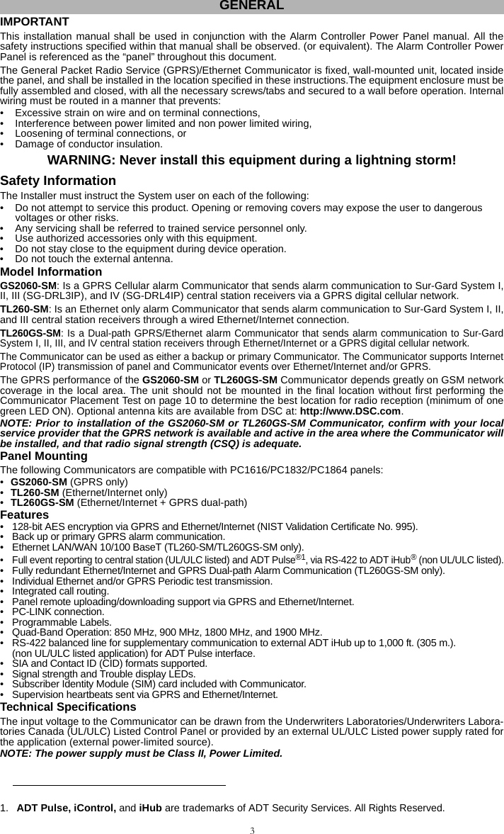
![4UL/ULC Installation RequirementsNOTE: For equipment used at the protected premises and intended to facilitate IP communications (hubs,routers, NIDs, Digital Subscriber Line (DSL), Cable modems), 24 hour back-up power is required. Wheresuch cannot be facilitated, a secondary (back-up) communication channel is required. Domain Name Service (DNS) programming is not permitted in UL/ULC listed systems.Notes for using Private, Corporate, and High Speed Data Networks:Network access and domain access policies shall be set to restrict unauthorized network access, and spoofingor Denial of Service (DoS) attacks. Select an Internet Service Provider (ISP) that has redundant servers/sys-tems, back-up power, routers with firewalls enabled, and methods to identify and protect against DoS attacks(e.g., via spoofing).Notes for using Public Switched and Cellular Data Networks:Communication channels shall be facilitated such that the Communicator will restrict unauthorized access,which could otherwise compromise security. The Communicator shall be located in a secured area.•For ULC Residential Fire and Burglary applications the TL260GS-SM can be used as primary communica-tion channel via either GSM or Ethernet or as a back-up in conjunction with the Digital Alarm CommunicatorTransmitter (DACT). Test transmission every 24 hours shall be enabled on each channel.•For ULC Commercial Fire and Burglary applications the GS2060-SM and TL260GS-SM can be used as apassive communication module with the following Security Levels:• P1 (each channel GSM or Ethernet is independent), • P2 (GSM and Ethernet in back-up configuration, Panel Section [851][005] Toggle Option [5] OFF),• P3 (GSM and Ethernet in redundant configuration, Panel Section [851][005] Toggle Option [5] ON). • The Communicator can also be used as an Active communication system with the Security Levels A1-A4(each channel GPRS or Ethernet independent or together in a back-up/redundant configuration). For ActiveLine Security systems AES128 bit encryption shall be enabled (at the monitoring station receiver) and thesupervision heartbeat rate shall be set as 90 seconds (Panel Section [851][004] = 005A/90). The supervi-sion window at the Signal Receiver Center (SRC)'s receiver shall be programmed as maximum of 180 (00B4/180) seconds.•For UL Residential Fire and Burglary applications the GS2060-SM andTL260GS-SM can be used as theprimary communication channel via either GSM or Ethernet, or as a back-up in conjunction with the DACT (30 day test transmission is required on each channel). •For UL Commercial Burglary applications the TL260GS-SM can be used as Dual Signalling Line communi-cation system (GPRS and Ethernet channels used in redundant configuration), Standard Line Security andas Encrypted Line Security. • The supervision heartbeat shall be enabled (Panel Section [851][005] Toggle Option [1] (Ethernet) and/orToggle Option [2] (GSM) shall be ON), Toggle Option [3] (Supervision Type) shall be ON and the supervisionheartbeat rate shall be selected as 135 (0087/135) seconds. Option [004] = 0087. The supervision windowat the supervising station shall be maximum 200 (00C8/200) seconds. For Encrypted Line Security systemsthe encryption AES128 bit shall be enabled at the monitoring station receiver.•For UL Commercial Burglary installations, the GS2060-SM is listed as a primary (sole) communicationmeans (heartbeat must be enabled) or for supplementary (back-up) use in conjunction with a Plain Old Tele-phone Service (POTS) line dialer. When the heartbeat transmission over the Ethernet or GPRS network isenabled, using the TL260GS-SM with a compatible control unit listed for standard/encrypted line security, itcan provide line security for the alarm system over the primary line. • The TL260GS-SM is also suitable to be used with a compatible control unit listed for dual line security trans-mission when used in conjunction with a DACT or a Public Switched Data Network (PSDN) transmitter,where the PSDN provides the line security and is the primary line. In this mode, alarm signals are requiredto be sent simultaneously over both communication methods.RatingsCompatibility Table 1: Communicator RatingsModel GS2060-SM GPRS only TL260-SMEthernet only TL260GS-SMEthernet & GPRS POWER SUPPLY RATINGSInput Voltage Nominal 12 VDC: The panel Bell output shall be derated:700mA - (Communicator mA) = (derated Bell output). CURRENT CONSUMPTIONStandby Current90mA @ 13.66V 100mA @ 13.65V 120mA @ 13.66VAlarm (Transmitting) Current400mA @ 12VOperating FrequencyQuad band 850MHz, 900MHz, 1800MHz, 1900MHzTypical Antenna Gain2dBiENVIRONMENTAL SPECIFICATIONSOperating Temperature 32°F - 120°F (0°C - 49°C) Humidity 5% ~ 93% relative humidity, non-condensingMECHANICAL SPECIFICATIONSBoard Dimensions (mm) 100 × 150 × 15 100 × 150 × 18 100 × 150 × 15 Weight (grams) with bracket 310 290 320](https://usermanual.wiki/Tyco-Safety-Canada/10GS260LSM.Users-Manual-2/User-Guide-1469163-Page-6.png)
![5NOTE: Enter [*][8][Installer Code][900] at keypad to view the Panel Version number.Products or components of products, which perform communications functions only shall comply with therequirements applicable to communications equipment as specified in UL60950 or CAN CSA C22.2. No.60950-1, Information Technology Equipment - Safety - Part 1: General Requirements. Where network inter-faces are internal to the control unit or receiver, compliance to CAN CSA C22.2. No. 60950-1 is adequate. Suchcomponents include, but are not limited to: hubs; routers; NIDs; Third party communications service providers;DSL modems; and Cable modems.Software CompatibilityThe Communicator is compatible with the following ADT Pulse software:• iControl Interactive.• System Administrator.ADT PulseNOTE: This application has not been investigated by UL/ULC and is not used on UL/ULC certifiedinstallations.The Communicator provides ADT Pulse Level 1, 2, and 3 monitoring and control via an RS-422 interface to anexternal iHub. The default Keybus link speed is 115.2 KB and this option is programmable by the installer. Alllife-safety events are encrypted and transmitted by the GPRS path to the central monitoring station (Level 1).All life-style events are transmitted by the RS-422 link, using ITv2.0 protocol to the iHub, and then to remote theiControl Servers (Level 2 and Level 3).NOTE: iControl’s iHub is an interface device which connects to security panels, IP cameras, sensors, Z-wave based home automation devices, etc. to deliver a host of advanced functionality.NOTE: Life-style events are “non alarm” events. Life-safety events are “alarm” events.There are three ADT Pulse levels, defined as follows:•.L1: GPRS Remote Control of Arm/Disarm and notification for doors and windows. All life-safety and life-style events are transmitted on the GPRS channel only.•L2: Broadband with Z-Wave and L1. Life-safety events use GPRS channel. Life-style events use RS-422.•L3: Broadband with L1, L2, and video. Life-safety events use GPRS channel. Life-style events use RS-422.The following features are available with the RS-422 ADT Pulse Interface:• Communicator faults can be transmitted. • Panel communication errors are reported to the ADT iHub.• Real time reporting of Zone status information to the ADT iControl Server.• Remote update of the Communicator (flash upgrade).• SMS incoming “wake up” for the GPRS channel.• WEB login to request an incoming session with the Communicator.• Zone Label Programming. NOTE: Communicator buffers 1,000 date/time stamped Life-Style events to iHub as First In First Out (FIFO). EncryptionThe Communicator uses 128 Bit AES Encryption. Encryption can only be enabled from the monitoring stationreceiver. Each receiver (Ethernet 1 and 2, GPRS 1 and 2) can independently have encryption enabled or dis-abled. When encryption is enabled, the central station will configure the device to encrypt communications thenext time the Communicator module performs a communication to that receiver. NOTE: Packets will start being encrypted only after the next event is sent to that receiver, or if the unitis restarted.Before leaving the installation site, the Communicator TL260-SM/TL260GS-SM Ethernet line shall be connected via an APPROVED (acceptable to the local authorities) Network Interface Device (NID) (e.g., for UL Installations, U60950 listed NID). All wiring shall be performed according to the local electrical codes.This GPRS/Ethernet Communicator shall be installed by Service Persons only. (Service Person is defined as a per-son having the appropriate technical training and experience necessary to be aware of hazards to which that personmay be exposed in performing a task and can also take measures to minimize the risks to that person or other per-sons). The Communicator shall be installed and used within an environment that provides the pollution degree max2, overvoltages category II, in non-hazardous, indoor locations only. This manual shall be used with the InstallationManual of the panel which is connected to the GPRS/Ethernet Communicator. All instructions specified within thepanel manual must be observed.All the local rules imposed by local electrical codes shall be observed and respected during installation.Table 2: Compatible Receivers, and PanelsCommunicator Receiver/Panel DescriptionGS2060-SMTL260-SMTL260GS-SMReceiver• Sur-Gard System I Receiver, version 1.30+• Sur-Gard System II Receiver, version 2.10+• Sur-Gard SG-DRL3-IP, version 2.30+ (for Sur-Gard System III Receiver)• Sur-Gard SG-DRL4-IP version 1.20+ (for Sur-Gard System IV Receiver)Panel • Power Series PC1616, version 4.5+• Power Series PC1832, version 4.5+• Power Series PC1864, version 4.5+ PRE INSTALLATION CONFIGURATIONCOMMUNICATOR INSTALLATION CONFIGURATION](https://usermanual.wiki/Tyco-Safety-Canada/10GS260LSM.Users-Manual-2/User-Guide-1469163-Page-7.png)
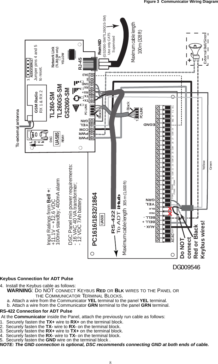
![9Install Network Cable (TL260-SM/TL260GS-SM only)Route the CAT 5 Ethernet cable through back of the panel and plug it into the Communicator’s RJ45 jack.Before leaving the premises the Ethernet communication lines must first be connected to an approved (acceptable to local authorities) type NID, (UL installations, UL 60950 listed NID, for ULC installations CAN/CSA C22.2. No. 60950-1 Certified NID). All wiring shall be performed according to the local electrical codes.6. Perform the following steps for initial power on of the panel with Communicator installed:a. Reconnect the AC power, telephone line, and battery + connector to the panel. (the Communicator andPanel will power up together).b. Observe that the Communicator’s red and yellow LEDs are flashing together while it initializes. The redand yellow LEDs will continue to flash until the Communicator has successfully communicated to all pro-grammed receivers. If this is the first time the Communicator has been powered up in the panel, the mod-ule will initiate communication to request programming remotely.NOTE: Initialization may take several minutes to complete. red and yellow LEDs will flash together dur-ing initialization. Do not continue to next step until the red and yellow LEDs have stopped flashing. (Ifonly the yellow LED is flashing, there is a Communicator trouble and the Green LEDs are not valid forCommunicator Placement Test). Correct trouble indicated by flashes on yellow LED before continuing.(See Table 5 for troubleshooting assistance).7. GS2060-SM/TL260GS-SM only: Perform the Communicator Placement Test on page 10.8. Mount the Panel in final location indicated by placement test. Domain Name Service (DNS) programming is not permitted in UL/ULC listed systems.Keypad Data Display•Section-Toggle Options: The number is displayed when Toggle is ON, the number is not displayed whenToggle is OFF. (e.g., Toggle Options displays: [--3--6--]. Options 3 and 6 are ON, all others are OFF). Press-ing keys 1 through 8 will alternately turn the Toggle ON and OFF.•HEX/Decimal Data: Values that are provided with two defaults, separated by a “/” character, use the format:hexadecimal followed by decimal equivalent (e.g., Default [0BF5/3061]). Hexadecimal numbers are shown,with all leading zeroes, to the full field length defined for the number.Entering HEX values at keypadTo enter HEX values at the keypad, you must press the * key before entering the HEX value. (e.g., to enter “C” at the keypad, press [*][3]. Entering ASCII Characters at keypad1. Press [*] and use scroll buttons [<] [>] to display “ASCII Entry” on the LCD screen. 2. Press [*] to select ASCII entry mode. 3. Use the [<] [>] scroll keys to display the character you want and press [*] to save and exit ASCII. 4. Repeat the steps above to enter another ASCII character.PC1616/1832/1864 Initial ProgrammingPerform the following steps to ensure that the Communicator and the Panel work together as intended.These Sections must be programmed at the panel keypad. Enter [*][8][Installer Code][Section Number]. Recordany values that are modified from their default, in the appropriate Worksheets for the Panel or Communicator. 1. In Panel Section [167] program 060 (seconds).2. In Panel Section [382] set Option [5] ONNOTE: If this option is OFF, the yellow status LED on the Communicator will indicate ‘Panel Supervision Trou-ble’ (2 flashes) and the unit can not be programmed via the PC-LINK cable.3. In Panel Section [383] [2] set Option [7] ON.4. In Panel Section [383] [2] set Option [8] ON for CID, or OFF for SIA.5. A valid Account Number must be entered in Communicator Section [851][021]. See Programming Section.NOTE: DSC recommends using the same Account Number for Panel and Communicator.6. In Panel Sections [301], [302], and [303], program the central station telephone number that will be used forthe GPRS/Ethernet Communicator. Valid entries are:a. A valid telephone number; signals will be routed to the central station using the Public Switched Tele-phone Network (PSTN). b. DCAA (Receiver 0); signals will be routed to GPRS/Ethernet Receivers 1 - 4 depending on programmingToggle Options in Communicator Section [851][006].c. Panel Section [301] sets the Primary communication path, and may be configured as either PSTN orCommunicator routing. Panel Section [302] is redundant, and Panel Section [303] is the backup tele-phone number for Panel Section [301]. Refer to the Panel manual for additional information.NOTE: The leading digit ‘D’ (dial tone detection) in the telephone number is pre-programmed.7. In Panel Section [350], program the communication format as: CID (03) or SIA FSK (04). NOTE: If any of the Panel telephone numbers have been set to DCAA, section [350] must be set to (04).8. In Panel Sections [351] - [376], program the Communicator call direction options. Refer to the Panel Installa-tion Manual for details on setting these options.9. In Panel Section [401] set Toggle Option [2] ‘User Enable DLS’ to ON in order to perform panel DLS sessionthrough GPRS or Ethernet.NOTE: Before leaving the premises, the installer should verify all programmed communications paths.See Programming Options Section [851][901] to send immediate test transmissions.Communicator Troubles displayed on a PC1616/1832/1864The General System trouble is the only trouble that will appear on the keypad Liquid Crystal Display (LCD)when encountered by a Communicator installed in a PC1616/1832/1864. For more information about the trou-ble on the Communicator module refer to the panel event buffer. Log entry will show Fault or Restore for eachof the following events: INITIAL PANEL PROGRAMMING](https://usermanual.wiki/Tyco-Safety-Canada/10GS260LSM.Users-Manual-2/User-Guide-1469163-Page-11.png)
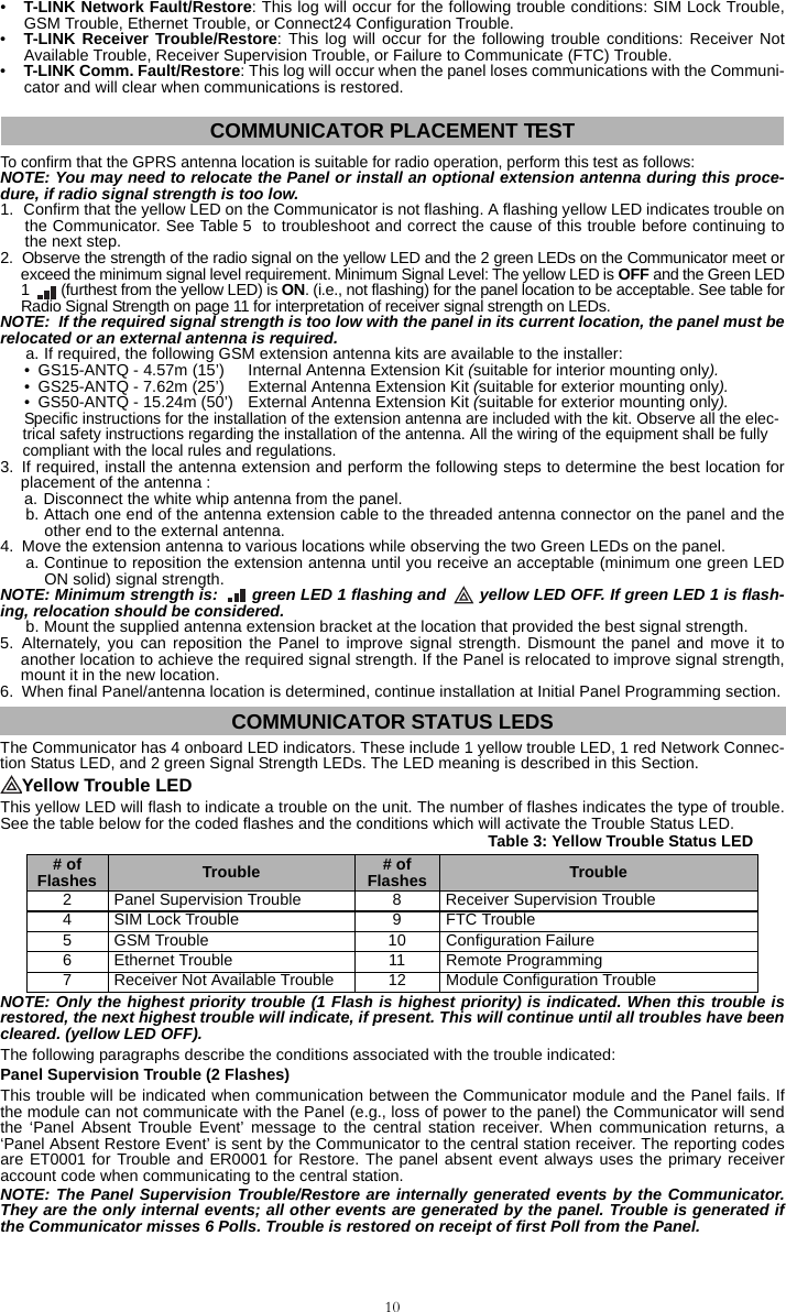
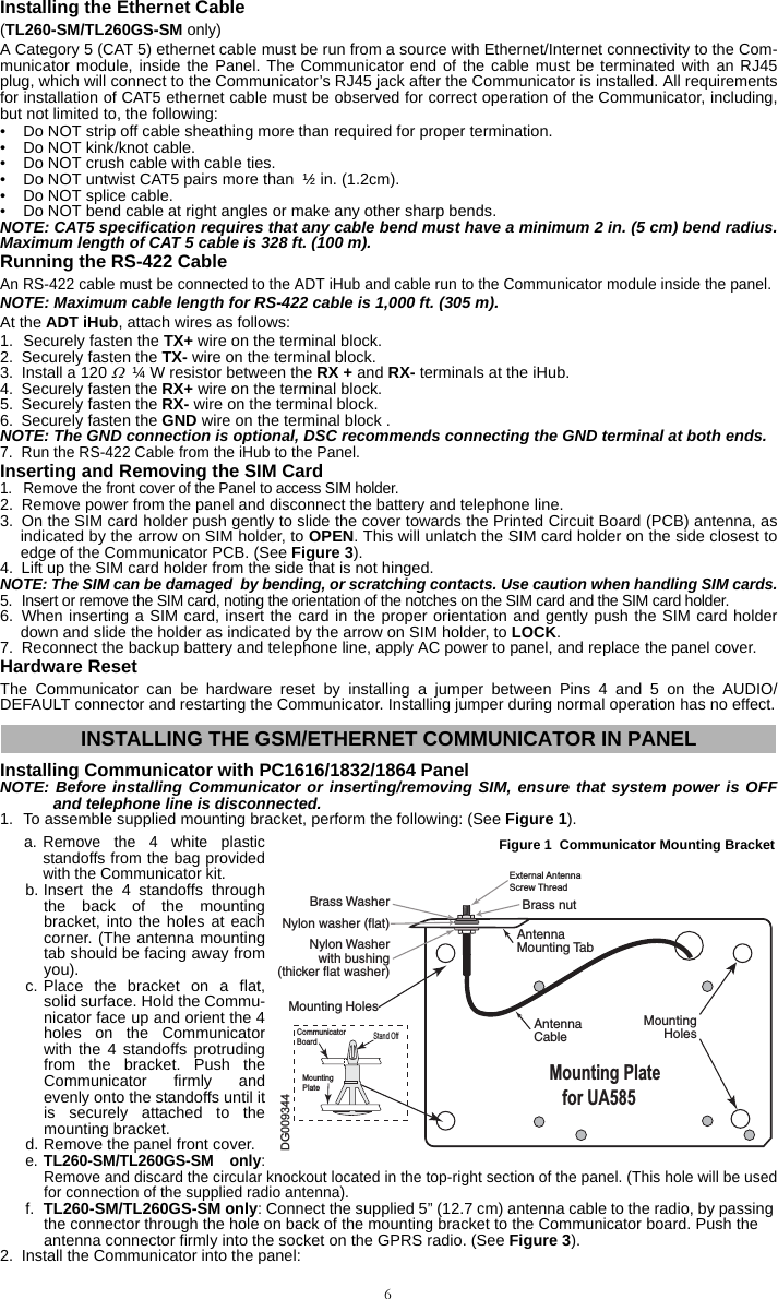
![11SIM Lock Trouble (4 Flashes)This trouble will signify that the SIM lock feature has been enabled and the unit has not been programmed withthe correct PIN for the SIM card.GSM Trouble (5 Flashes)This trouble is indicated for any of the following 4 conditions: 1. Radio Failure: Trouble is indicated after 8 failed attempts to communicate with the GPRS radio.2. SIM Failure:Trouble is indicated after 10 failed +CPIN commands. 3. GPRS Network Trouble: Trouble is indicated for loss of the registration to the network provider. (3 consecu-tive init or refresh failures, failure to connect to an APN, failure to open a socket, total error count in cycliccommand = 20, or on receiving an MSDI (1/2), (7/8/14). Trouble will clear after init and cyclic commands suc-ceed and MIPCALL and MIPOPEN commands succeed.4.Insufficient Signal Strength: Trouble is indicated if calculated average signal strength is too low. (Both greenLEDs are OFF). Trouble will clear when the calculated average signal strength is above minimum (i.e., > CSQ 5).Ethernet Trouble (6 Flashes)This trouble is indicated when Ethernet link between the transmitter and the local switch or router is absent.This trouble will also be indicated if the unit fails to get Dynamic Host Control Protocol (DHCP) settings from theDHCP server. (Not active if Ethernet Receivers are not programmed).Receiver Not Available (7 Flashes)This trouble is indicated if the unit is not able to successfully initialize with any of the programmed receivers.Unprogrammed receivers are excluded. This trouble is also indicated if the GPRS receiver APNs have not beenprogrammed in Sections [205] and [215].Receiver Supervision Trouble (8 Flashes)This trouble is indicated when receiver supervision is enabled and communication between the Communicatormodule and the receiver fails. Trouble is indicated if Ethernet 1 is supervised and does not receive a heartbeatfrom the receiver or if GPRS is supervised and the unit does not receive an acknowledgment to 4 heartbeatssent to the receiver.FTC Trouble (9 Flashes)This trouble is indicated when the unit fails to communicate module events to the central station. Trouble is dis-played after the unit has exhausted all communications attempts to all programmed receivers for events gener-ated by the Communicator.Configuration Failure (10 Flashes)This trouble is indicated when the unit fails to receive remote programming.Remote Programming (11 Flashes)This trouble is indicated during a remote firmware upgrade. Indicates that a remote firmware update is in prog-ress over GPRS/Ethernet. Trouble will clear automatically when update completes successfully.Module Configuration Trouble (12 Flashes)This trouble is indicated when the System Account Code or the Receiver Account have not been programmed.Disabled receivers are excluded. Red Network Connection Status LED (TL260-SM/TL260GS-SM)BLINKING: Indicates communications in progress.• Once quickly for outgoing Ethernet transmission.• Twice quickly to indicate incoming Ethernet ACK/NACK.OFF: This is the normal state of the Red Network Connection Status LED. There are no network connectionissues present. ON: There is a problem with the Ethernet or the GPRS network connection. LED will be ON if any of the following occur:• Ethernet cable is not connected,• DHCP configuration times out,• Unit fails to get an IP address from the GPRS network, or• GPRS connection has been reset. (Green LED 1) (Green LED 2) and (Yellow LED) Signal Strength NOTE: If the yellow LED is flashing, Signal Strength in table below is not valid. See Table 5 for troubleshooting flashing yellow LED.NOTE: The Communicator will indicate GSM Trouble (yellow LED = 5 flashes) if the average CSQ Levelis 5 or less. The Communicator Signal Strength can be viewed remotely.Table 4: Radio Signal StrengthSignal Strength CSQ Level Yellow LED Green Led 2 Green LED 1 Signal Level dBm Action RequiredNo Signal 0 ON OFF OFF -108.8 • Check all antenna connections. • Confirm GPRS service is active in area. • Relocate Panel or install external antenna.1 Bar 1 - 4 ON OFF Flashing -108 ~ -103 Relocate Panel or install external antenna if Yellow Trouble LED has: 5 flashes.2 Bars 5 - 6 OFFSee Note OFF Flashing -102 ~ -99 3 Bars 7 - 10 OFF OFF ON -98 ~ -91 Location is OK. GPRS Signal Strength is greater than CSQ 5.4 Bars 11-13 OFF Flashing ON -90 ~ -85 5 Bars 14 + OFF ON ON -84 and higher](https://usermanual.wiki/Tyco-Safety-Canada/10GS260LSM.Users-Manual-2/User-Guide-1469163-Page-13.png)

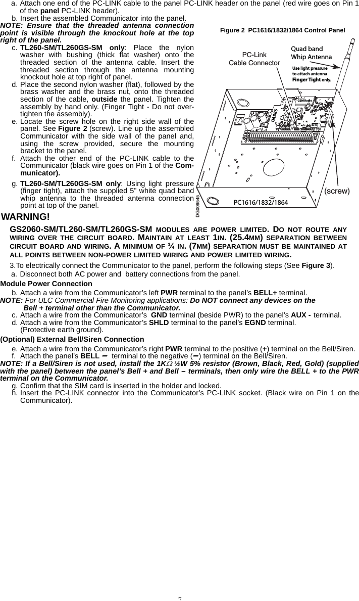
![13APPENDIX A: COMMUNICATOR TROUBLESHOOTINGTable 5: Trouble LED indicationsTrouble indication Possible Causes Trouble Possible SolutionNo Indication No Power• Check the power connections between the Panel and the Communicator.• Confirm PC-LINK cable is properly installed between communicator and panel.Yellow LED – ON Solid Insufficient Signal Strength• Confirm that GPRS network service is active in your area.• Ensure the antenna is securely connected to the radio. Check antenna stub cableis securely connected to the radio.• If an external antenna is used ensure the antenna is securely screwed on to theantenna cable connector. Check external antenna for damage or open/short.Trouble LED – 2 FlashesPanel Supervision Trouble• Check Section [382]Toggle Option[5] is ON.(GPRS/Ethernet Module Enabled)• Ensure the PC-LINK cable between the Panel and Communicator is connectedproperly (not reversed) and is securely in place.Yellow LED - 4 Flashes Lockout Trouble• The SIM card has incorrect PIN programmed or has a PIN that the module doesnot recognize. Replace the SIM card.Yellow LED – 5 Flashes GSM Trouble• Confirm that GPRS service is available and active in your area. • Check all antenna connections. •Ensure average radio signal strength is CSQ 6 or higher. (See Table 4 ).• Ensure the SIM card is properly inserted into the SIM card holder.• Ensure the SIM card has been activated. (Could take up to 24 hrs after install).• If this trouble persists, you must relocate the Panel (and Communicator) or installan external antenna extension kit.Yellow LED – 6 Flashes Ethernet Trouble• Check with your ISP to confirm Internet service is active in your area.• Ensure your Ethernet cable is securely inserted into the RJ45 jack of the Commu-nicator and the Hub/Router/ Switch.• Check the link light on the Hub/Router/ Switch is ON . If link light is OFF, try restart-ing the Hub/Router/ Switch. • If DHCP is used, ensure that the unit has an assigned IP address from the server.In Panel Section [851] [992] verify a valid IP address is programmed. If not, con-tact the Network administrator.• If problem persists, replace the Ethernet cable and RJ45 connector.Yellow LED – 7 Flashes Receiver Not Available• Ensure that the Ethernet path has internet connectivity.• If you are using a static IP address make sure the gateway and subnet mask areentered correctly.• If the network has a firewall, ensure the network has the programmed outgoing ports open (Default UDP Port 3060 and Port 3065).• Ensure that all the receivers are programmed for DHCP or have the proper IPaddress and port number.• Ensure the GPRS Receiver APNs have been programmed with the Access PointName provided by your GPRS provider.Yellow LED – 8 FlashesReceiver Supervision Trouble• This trouble is indicated when supervision is enabled and the unit is not able tosuccessfully communicate with the receiver.• If this trouble persists, contact your central station.Yellow LED - 9 Flashes FTC Trouble• The unit has exhausted all communications attempts to all programmed receiverfor events generated by the Communicator.• Restart the system, if trouble persists, contact your dealer.Yellow LED – 10 FlashesConnect24 Configuration Failure• This trouble is indicated when the SIM is active but there is no programming forthe unit.• Ensure a profile has been programmed in Connect 24 for the SIM.• You can confirm your programming by calling the Connect 24 VRU, or by logginginto the Connect24 VRU web site.Yellow LED – 11 Flashes Remote Programming• The LEDs will flash when a remote firmware upgrade is in progress over Ethernetor GPRS. The LEDs will extinguish when update is complete.• The LEDs will flash to indicate a remote programming session is active overEthernet or GPRS. The LEDs will extinguish when the session terminates.Yellow LED – 12 FlashesModule Configuration TroubleThis indication appears when Section [021] System Account Code or Section [101]; [111]; [201]; and [211] Receiver Account Code have not been pro-grammed. Ensure that a valid account code has been entered in these Sections.All LEDs flash-ing together Boot Loader Failed Disconnect power, then reconnect power to the Communicator module. Red and Yellow LEDs flashing togetherInitialization SequenceThe unit is still initializing please wait while the unit gets its programming and estab-lishes a connection to all programmed receivers. Note that this process may take several minutes.Only Green LEDs flashing Hardware Default JumperThe hardware default jumper must be removed. See Figure 3.](https://usermanual.wiki/Tyco-Safety-Canada/10GS260LSM.Users-Manual-2/User-Guide-1469163-Page-15.png)
![14The Programming Sections in this document are accessed via panel Section for Ethernet/GPRS Programming.Enter: [*][8][installer code][851][###], Where ### is the 3 digit Section number referenced in this document.The Programming Worksheets at the end of this document can be used to record the new values when pro-gramming changes have been made from the default values. Default values are provided for each Section.Programming Sections cannot be modified from the keypad. Installers may review/record programming Optionsat the keypad.NOTE: Ethernet/GPRS Programming Sections accessed through the keypad are for display purposesonly. Configuration changes must be done remotely. Specified panel Sections must be configured forproper operation of the Communicator and the Panel. System Options[001] Ethernet IP AddressDefault (000.000.000.000)Enter the IP address of the Communicator. Ensure that the IP address is unique to your Communicator on the local network. Format is 4 fields, each field is a 3 digit decimal number. Valid range: 000-255. If an IP address is pro-grammed in this Section, the unit will operate with Static IP (DHCP disabled). Sections [002] and [003] must also be programmed when using Static IP addresses.NOTE: Default for this Section is Dynamic Host Configuration Protocol (DHCP) enabled. When enabled,the DHCP Server will set values for: IP Address [001], Subnet Mask [002], and Gateway [003]. Program-ming an IP address in this Section will disable DHCP (Static IP).[002] Ethernet IP Subnet Mask Default (255.255.255.000)Enter the Ethernet IP Subnet Mask of the dual Communicator. Format is 4 fields, each field is a 3 digit decimal number. Valid range: 000-255. NOTE: If DHCP is enabled, the DHCP Server will assign the subnet mask for this Section and the programmed value will be ignored.[003] Ethernet Gateway IP Address Default (000.000.000.000)Enter the Ethernet Gateway IP address of the Communicator. The gateway IP address is required when a router is used on the local network to reach the destination IP address specified in Section [001]. Format is 4 fields, each field is a 3 digit decimal number. Valid range: 000-255.NOTE: If DHCP is enabled, the DHCP Server will assign the Gateway IP address for this Section and theprogrammed value will be ignored.[004] Receiver Supervision IntervalDefault (0087/135)When receiver supervision is enabled (ON) in Section [005] Toggle Option [3], the unit sends heartbeats to Ethernet Receiver 1 or GPRS Receiver 1 to test the communications path. Use this Section to set the interval time (in sec-onds) when heartbeats will be sent. Valid range 000A-FFFF seconds. If the programmed value is less than (000A/10) seconds, supervision is disabled.•Receiver Window: This is the supervision timeout that must be configured at the central station receiver.•Recommended Values: This is the recommended heartbeat interval that should be programmed into theCommunicator.• For ULC passive systems (not using heartbeat supervision), the Daily test transmission must be enabledover each available communication channel Sections [125] and [225]. When programming with Connect24,the recommended intervals will be programmed automatically when the required window is selected.[005] System Toggle Options[1] Ethernet Receiver 1 Supervised Default (OFF) (TL260-SM/TL260GS-SM only).ON: Ethernet Receiver 1 will be supervised and heartbeats will be sent to Ethernet Receiver 1 based on thesupervision interval programmed in Section [004].OFF: Ethernet Receiver 1 will not be supervised. When disabled, heartbeat 1 is sent to the Ethernet receiveronce every hour, regardless of supervision type (heartbeat 1 or 2). The heartbeat is resent every 5 seconds untilACK. If no event or heartbeat ACK is received after (Receiver Supervision Interval + 75 seconds), Supervisorytrouble is indicated.NOTE: Ethernet Receiver 2 can not be supervised.[2] GPRS Receiver 1 Supervised Default (OFF)ON: GPRS Receiver 1 will be supervised and heartbeats will be sent to GPRS Receiver 1 based on the super-vision interval programmed in Section [004]. If ACK to heartbeat is not received, it is retransmitted every 5 sec-onds. Failure to ACK 2 consecutive heartbeats will reset the radio.COMMUNICATOR PROGRAMMING SECTIONSTable 6: Supervision Intervals for UL/ULCJurisdiction Receiver Window (Timeout) Recommended Supervision IntervalUL Commercial Burglary 200 seconds (0087/135) secondsUL Residential Fire 30 days Panel Test Transmission UL Residential Burglary 30 days Panel Test Transmission ULC Commercial Burglary Active 180 seconds (005A/90) secondsULC Commercial Burglary Passive 24 hours Panel Test Transmission ULC Commercial Fire Active 180 seconds (0073/115) secondsULC Commercial Fire Passive 24 hours Panel Test Transmission](https://usermanual.wiki/Tyco-Safety-Canada/10GS260LSM.Users-Manual-2/User-Guide-1469163-Page-16.png)
![15OFF: GPRS Receiver 1 will not be supervised. When disabled, heartbeat is not sent to the receiver.NOTE: GPRS Receiver 2 can not be supervised.[3] Supervision Type Default (OFF)ON: Heartbeat 1 (Commercial Supervision). This supervision type is suitable for applications where swap detec-tion is required on the supervisory packet.OFF: Heartbeat 2 (Residential Supervision). This supervision type is suitable for applications where supervisionof the communication path to the receiver is required. (no swap detection).NOTE: Commercial supervision is more data intensive than residential supervision and should only beused when required to meet the approval for the installation.[4] GSM PrimaryDefault (OFF - TL260-SM/TL260GS-SM) (ON - GS2060-SM)ON: GPRS channel is the primary path. Ethernet channel is the secondary path, if it exists.OFF: Ethernet channel is the primary path in a dual Communicator. GPRS channel is the secondary path.[5] Redundant Communications Default (OFF) (TL260GS-SM only)ON: Events will be communicated to Ethernet Receiver 1 and GPRS Receiver 1 at the same time. Events will becommunicated to Ethernet Receiver 2 and GPRS Receiver 2 at the same time. As long as the event is successfullycommunicated to 1 of the 2 paths (Ethernet or GPRS) the Communicator will move on to the next event.NOTE: Do not configure Ethernet Receiver 1 and GPRS Receiver 1 to communicate using a commonreceiver configuration (i.e., identical Receiver IP address and Receiver Remote Port). OFF: Events will be communicated to the receivers individually.NOTE: Toggle should be OFF when guaranteed message delivery to both receivers is required.[6] Remote Firmware Upgrade Default (ON)ON: The Communicator module firmware can be remotely upgraded using the Ethernet/GPRS paths.OFF: The Communicator module firmware can not be remotely upgraded. Local firmware upgrade is still possible.[7] Alternate Test Transmissions Default (OFF).ON: When the periodic test transmission interval occurs, the test transmission will alternate between being sentto the primary and secondary receivers with each test transmission interval.OFF: When the periodic test transmission interval occurs, the test transmission will be sent to the programmedreceivers, based on the settings of the periodic test transmission reporting codes.[8] GSM Low Signal Trouble. Default (OFF).[006] System Toggle Options 2[1] Ethernet 1 Receiver Enabled. Default (ON) (OFF for GS2060-SM).ON: Ethernet Receiver 1 is enabled. OFF: Ethernet Receiver 1 is disabled.[2] Ethernet 2 Receiver Enabled. Default (ON) (OFF for GS2060-SM).ON: Ethernet Receiver 2 is enabled. OFF: Ethernet Receiver 2 is disabled.[3] Reserved. (OFF).[4] GPRS 1 Receiver Enabled. Default (ON).ON: GPRS Receiver 1 is enabled. OFF: GPRS Receiver 1 is disabled.[5] GPRS 2 Receiver Enabled. Default (ON).ON: GPRS Receiver 2 is enabled. OFF: GPRS Receiver 2 is disabled.[6] Reserved (OFF).[7] DLS Over GPRS. Default (ON).NOTE: Program this toggle as OFF if you want to completely disable DLS from using the GPRS path. ON: DLS is enabled on the GPRS path. OFF: DLS is disabled on the GPRS path.NOTE: If this Toggle is OFF, DLS sessions will occur on the Ethernet path only, regardless of PrimaryPath set in Section [005] Toggle Option [4]. If it is ON then the Communicator will connect to the Primarypath first for DLS and if the session fails, the Secondary path will be used.[8] Interactive over GPRS. Default (ON). [007] DNS Server IP 1 Default (000.000.000.000)Programming this Section is not permitted on a UL/ULC listed system. Enter the IP address for DNS Server 1. Format is 4 fields, each field is a 3 digit decimal. Valid range: 000-255. NOTE: If no value is programmed and DHCP is used, the DHCP Server will configure the address. If anaddress is programmed and DHCP is used, the address that you program will be used instead of theDHCP address.](https://usermanual.wiki/Tyco-Safety-Canada/10GS260LSM.Users-Manual-2/User-Guide-1469163-Page-17.png)
![16[008] DNS Server IP 2 Programming this Section is not permitted on a UL/ULC listed system. Default (000.000.000.000)Enter the IP address for DNS Server 2. Format is 4 fields, each field is a 3 digit decimal. Valid range: 000-255. NOTE: If no value is programmed and DHCP is used, the DHCP Server will assign this value. If anaddress is programmed and DHCP is used, the address that you program will be used instead of theDHCP address.Programming Options[011] Installer CodeDefault (CAFE)Program your installer code for this Communicator module. The installer code will be required when programming the Communicator module. Valid range: 0000 - FFFF.[012] DLS Incoming Port Default (0BF6/3062)The DLS Incoming Local Port (listening port) is the port DLS IV will use when connecting to the Communicator. If a router or gateway is used, it must be programmed with a Transmission Control Protocol (TCP) port forward for this port to the Communicator module IP address. Valid range: 0000-FFFF.[013] DLS Outgoing Port Default (0BFA/3066)The DLS Outgoing Port is used for outgoing session to DLS IV after an SMS request has been sent to the Commu-nicator. Use this Section to set the value of the local outgoing port. The value must be changed if the Communicator is located behind a firewall and must be assigned a particular port number, as determined by your network adminis-trator. In most cases, changing the default value or configuring your firewall with this port is not required. Valid range: 0000-FFFF.NOTE: If Section [006] Toggle Option [7] is ON. DLS will use the Primary path for session. If Section[006] Toggle Option [7] is OFF DLS will use the Ethernet path, if available.[020] Time ZoneDefault (00)Use Offset Hours column to find your local time zone offset from GMT/UTC. Record the two digit HEX valuefrom the HEX column on same row. Program this HEX value as your Time Zone. Valid range is 00 - FF.Table 7: Time Zone OffsetHEX OffsetHours StdAbbrev Location HEX OffsetHours StdAbbrev Location01 -12 BIT Baker Island Time 47 +5.5 IST Indian Standard Time05 -11 NUT Niue Time 48 +5.75 NPT Nepal TimeSST Somoa Standard Time49 +6XJT Xinjiang Standard Time09 -10HAST Hawaii-Aleutian Standard Time EKST East Kazakhstan Standard TimeTHAT Tahiti Time LKT Sri Lanka TimeTKT Tokelau Time VOST Vostok TimeCKT Cook Island Time OMSK Omsk Standard Time0B -9.5 MIT Marquesas Island Time NOVT Novosibirsk Time0D -9 AKST Alaska Standard Time BTT Bhutan TimeGIT Gambier Island Time BIOT British Indian Ocean Time11 -8PST Pacific Standard Time 4B +6.5 CCT Cococ Islands TimePST Pitcarirn Standard Time MMT Myanmar TimeCIST Clipperton Island Standard Time4D +7CXT Christmas Island Time15 -7 MST Mountain Standard Time KOVT Khovd Time19 -6CST Central Standard Time KRAT Krasnoyarsk TimeGALT Galapagos Time WIB Waktu Indonesia Bagian BaratPIT Peter Island Time ICT Indochina TimeEAST Easter Island Standard Time BDT Bangladesh Standard Time](https://usermanual.wiki/Tyco-Safety-Canada/10GS260LSM.Users-Manual-2/User-Guide-1469163-Page-18.png)
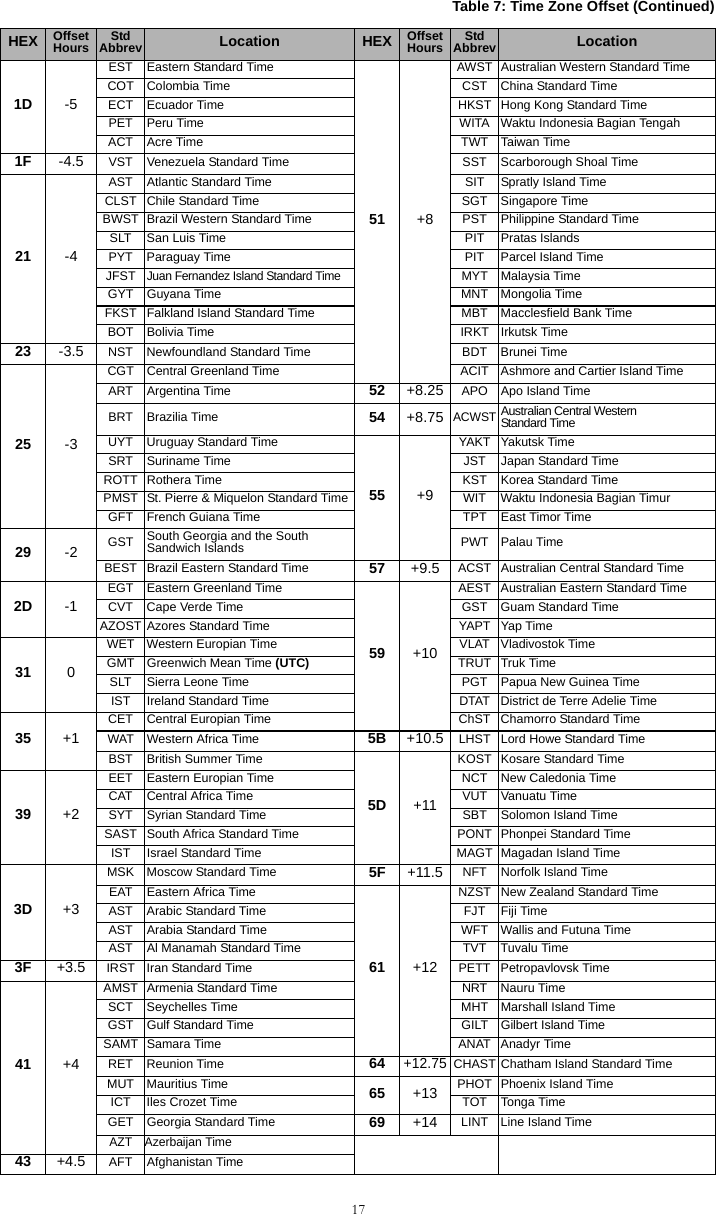
![18[021] Account CodeDefault (FFFFFF)The account code is included when transmitting any events generated by the Communicator. (e.g., Panel Absent Trouble). It is recommended that the account code be the same as the control panel account number. Valid range: 000001-FFFFFE. If 4 digit account codes are needed the 2 lowest digits shall be programmed as FF;(e.g., Account 1234 is programmed as:1234FF). NOTE: Programming this Section with all 0 or F will cause a Module Configuration Trouble (yellow LED=12 flashes).[022] Communications FormatDefault (04)Program 03 for Contact ID (CID). Program 04 for SIA. The module can be configured to send Communicator Events in SIA or CID format. The SIA communication format follows the level 2 specifications of the SIA Digital Communication Standard - October 1997. This format will send the account code along with its data transmission. The transmission will look similar to the following at the receiver. Example: Nri0 ET001Where: N = New Event; ri0 = Partition/Area identifier; ET = Panel Absent Trouble; 001 = Zone 001.Communications Reporting Codes[023] Panel Absent TroubleDefault (FF)Program 00 to disable this event or FF to enable. This event will occur when communications with the panel have been lost for more than 60 seconds.[024] Panel Absent Trouble RestoreDefault (FF)Program 00 to disable this event or FF to enable. This event will occur when communications with the control panel have resumed.[025] Radio Activation RestoreDefault (FF)Program 00 to disable this event or FF to enable. This event will occur after any successful Connect24 program-ming session.System Test Options [026 - 029]Test Transmissions to Primary Receiver, with Backup to Secondary Receiver: Set Ethernet Section [026] to (FF); [027] to (00). Set GPRS Section [028] to (FF); [029] to (00).• If the test transmission fails to the primary receiver it will backup to the secondary receiver.• If the test transmission fails to the secondary receiver an FTC trouble will be generated.Test Transmission Unique to Primary and Secondary Receivers:Set Ethernet Section [026] to (FF); [027] to (FF). Set GPRS Section [028] to (FF); [029] to (FF).• The module will send periodic test transmissions to each receiver independently, with no backups.• If the test transmission fails to any of the programmed receivers, an FTC trouble will be generated.45 +5CAST Chinese Atlantic Standard Time70 - FF ReservedWKST West Kazakhstan Standard TimePKT Pakistan TimeYEKT Yekaterinburg TimeUZT Uzbekistan TimeTMT Turkmenistan TimeTJT Tajikistan TimeTFT French Southern and Antarctic TimeMVT Maldives TimeMAWT Mawson TimeKGT Kyrgyzstan TimeHMT Heard and McDonald Island TimeDAVT Davis TimeTable 8: Communications Reporting CodesEvent SIA IdentifierSIA Reporting CodeCIDQualifierCID Event CodeCID Reporting CodeCID User/Zone[023] Panel Absent Trouble ET 001 1 3 55 001[024] Panel Absent Trouble Restore ER 001 3 3 55 001[025] Radio Activation Restore RS 001 3 5 52 001[026] Ethernet 1 Test Transmission RP 001 1 6 A3 951[027] Ethernet 2 Test Transmission RP 002 1 6 A3 952[028] GPRS 1 Test Transmission RP 003 1 6 A3 955[029] GPRS 2 Test Transmission RP 004 1 6 A3 956[030] FTC Restore YK 001 3 3 54 001Table 7: Time Zone Offset (Continued)HEX OffsetHours StdAbbrev Location HEX OffsetHours StdAbbrev Location](https://usermanual.wiki/Tyco-Safety-Canada/10GS260LSM.Users-Manual-2/User-Guide-1469163-Page-20.png)
![19Alternate Test Transmission:Alternate Test Transmission can be enabled or disabled in Section [005] Toggle Option [7].[026] Ethernet 1 TransmissionDefault (FF)Program 00 to disable this event transmission or FF to enable. See System Test Options (above) for details on settings. [027] Ethernet 2 TransmissionDefault (00)Program 00 to disable this event transmission or FF to enable. See System Test Options (above) for details on settings. [028] GPRS 1 TransmissionDefault (FF)Program 00 to disable this event transmission or FF to enable. See System Test Options (above) for details on settings. [029] GPRS 2 TransmissionDefault (00)Program 00 to disable this event transmission or FF to enable. See System Test Options (above) for details on settings. NOTE: The time interval (in minutes) between periodic tests is programmed in Section [125] (Ethernet)and Section [225] (GPRS).[030] FTC RestoreDefault (FF)Program 00 to disable this event transmission or FF to enable. This event will occur when an FTC Trouble on the system restores.[031] Panel Tamper Alarm Default (FF)This event will occur when a Panel Tamper is detected during the Entry Delay time. The Panel shall notify the Communicator immediately, creating a Priority Tamper Alarm condition. Setting this option to 00 will disable monitoring of this condition. See Table 9 for SIA and CID reporting codes. Program 00 to disable this event transmission or FF to enable event transmission. [032] Panel Tamper Alarm Restore Default (FF)Program 00 to disable this event transmission or FF to enable. This event will occur when a Panel Tamper event on the system restores. See Table 9 for SIA and CID reporting codes.Ethernet Receiver 1 Options [101] Ethernet Receiver 1 Account CodeDefault (0000000000)The account code is used by the central station to distinguish between transmitters. This account code is used when transmitting heartbeat signals to the central station receiver. Signals received from the Panel will use the con-trol panel account number. Valid range: 0000000001-FFFFFFFFFE. Programming this Section as all 0 or all F will cause a Module Configuration Trouble (yellow LED=12 flashes).NOTE: If Ethernet Receiver 1 and GPRS Receiver 1 are programmed as the same receiver (IP and portnumber are identical), Ethernet Receiver 1 account code will be used.[102] Ethernet Receiver 1 DNISDefault (000000)The Dialled Number Information Service (DNIS) is used in addition to the Account Code to identify the Communica-tor module at the central station. Valid range: 000000 - 099999. Value is entered as a leading 0 followed by the 5 digit DNIS. Format is Binary Coded Decimal (BCD.NOTE: Each Ethernet/GPRS receiver must be programmed with a unique DNIS.[103] Ethernet Receiver 1 AddressDefault (127.000.000.001)The default address enables the Communicator to operate in Unattended Mode. Unattended Mode is used when a receiver is not available and the unit is required to perform DLS sessions. Typi-cally used where the customer programs the control panel daily due to access control and still wants to receive alarms without buying extra hardware (receiver) or software. NOTE: When a valid IP address has been programmed, Ethernet Receiver 1 is enabled and will commu-nicate events over the Ethernet channel.Ethernet Receiver 1 and GPRS Receiver 1 may be configured to communicate to the same central station receiver. To configure the device to operate using this Common Receiver Mode functionality, program Ethernet Receiver 1 and GPRS Receiver 1, IP address and port number with identical values. NOTE: When operating in Common Receiver Mode, Ethernet Receiver 1 account code will be used forEthernet and GPRS.[104] Ethernet Receiver 1 Remote PortDefault (0BF5/3061)This Section determines the remote port of Ethernet receiver 1. Valid range: 0000 - FFFF.Table 9: Panel Tamper Reporting CodesEvent SIA IdentifierSIA Reporting CodeCIDQualifierCIDEvent CodeCIDReporting CodeCIDUser/Zone[031] Panel Tamper ES 001 1 1 45 001[032] Panel Tamper Restore EJ 001 3 1 45 001](https://usermanual.wiki/Tyco-Safety-Canada/10GS260LSM.Users-Manual-2/User-Guide-1469163-Page-21.png)
![20[105] Ethernet Receiver 1 Local PortDefault (0BF4/3060)Use this Section to set the value of the local outgoing port. Set the value of this port when your installation is located behind a firewall and must be assigned a particular port number as determined by your central station system administrator. Valid range: 0000 - FFFF.[106] Ethernet Receiver 1 Domain NameDefault ()Enter the Domain Name as 32 ASCII characters. Programming this Section is not permitted on a UL/ULC listed system. Ethernet Receiver 2 Options [111] Ethernet Receiver 2 Account CodeDefault (0000000000)The account code is used by the central station to distinguish between transmitters. The account code is used when transmitting heartbeat signals to the central station receiver. Signals received from the control panel will use the control panel account number. Valid range: 0000000001- FFFFFFFFFE. Programming this Section as all 0 or all F will cause a Module Configuration Trouble (yellow LED=12 flashes).NOTE: If both Ethernet Receiver 2 and GPRS Receiver 2 are the same receiver (IP and port number areidentical), Ethernet Receiver 2 account will be used for Ethernet and GPRS.[112] Ethernet Receiver 2 DNISDefault (000000)The DNIS is used in addition to the account code to identify the Communicator module at the central station. Valid range: 000000 - 099999. Value is entered as leading 0 followed by the 5 digit DNIS. Format is BCD.NOTE: Each Ethernet/GPRS receiver must be programmed with a unique DNIS.[113] Ethernet Receiver 2 AddressDefault (000.000.000.000)Programming the Ethernet receiver 2 IP address with 000.000.000.000 will disable Ethernet.Enter the Ethernet receiver 2 IP address. This address will be provided by your central station system administrator. Format is 4 fields, each field is a 3 digit decimal. Valid range: 000-255. NOTE: When a valid IP address has been programmed, Ethernet Receiver 2 is enabled and will commu-nicate events over the Ethernet channel.Ethernet Receiver 2 and GPRS Receiver 2 may be configured to communicate to the same central station receiver. To configure the device to operate using this common receiver mode functionality, program the Ethernet Receiver 2 and GPRS Receiver 2, IP address and port number with the same values. When operating in common receiver mode the Ethernet Receiver 2 account code will be used for communications over Ethernet and GPRS.NOTE: Do not program Ethernet Receiver 1 and Ethernet Receiver 2 to communicate to the samereceiver.[114] Ethernet Receiver 2 Remote PortDefault (0BF5/3061)This Section is used to program the port number used by Ethernet Receiver 2. Set the value of this port when your installation is located behind a firewall, and must be assigned a particular port number as determined by your cen-tral station system administrator. Valid range: 0000 - FFFF.NOTE: Do not program Ethernet Receiver 1 and Ethernet Receiver 2 Port with the same value. [115] Ethernet Receiver 2 Local PortDefault (0BF9/3065)Use this Section to program the value of the local outgoing port. You can set the value of this port when your instal-lation is located behind a firewall and must be assigned a particular port number as determined by your network administrator. Valid range: 0000 - FFFF. NOTE: Do not program Ethernet Receiver 1 and Ethernet Receiver 2 Port with the same value.[116] Ethernet Receiver 2 Domain NameDefault ( )Programming this Section is not permitted on a UL/ULC listed system. Enter the Domain Name as 32 Character ASCII.Ethernet Options [124] Ethernet Test Transmission TimeDefault (9999)Enter a 4 digit number (0000-2359) using the 24-hour clock format (HHMM) to set the test transmission time of day. Valid range: 00 - 23 hours (HH) and 00 - 59 minutes (MM). Programming a value of (9999) will disable the test transmission time.NOTE: The internal date and time will automatically be programmed when the unit communicates withthe primary receiver.[125] Ethernet Test Transmission CycleDefault (000000)This value represents the interval between test transmissions, in minutes. Valid range: 000000 - 999999 minutes. Once the unit has sent the initial periodic test transmission, all future test transmissions will be offset by the pro-grammed number of minutes. See Sections [026-029].NOTE: Minimum value is 000005 minutes. Programming an interval that is less than 5 minutes will dis-able test transmission.Table 10: Ethernet Test Transmission IntervalTest Transmission Interval Daily Weekly MonthlyProgrammed Minutes 001440 010080 043200](https://usermanual.wiki/Tyco-Safety-Canada/10GS260LSM.Users-Manual-2/User-Guide-1469163-Page-22.png)
![21GPRS Receiver 1 Options[201] GPRS Receiver 1 Account CodeDefault (0000000000)The account code is used by the central station to distinguish between transmitters. This account code is used when transmitting heartbeat signals to the central station receiver. Signals received from the control panel will use the control panel account number. Valid range: 0000000001 - FFFFFFFFFE. Programming this Section as all 0 or all F will cause a Module Configuration Trouble (yellow LED = 12 flashes).[202] GPRS Receiver 1 DNISDefault (000000)The DNIS is used in addition to the account code to identify the Communicator module at the central station. Valid range: 000000 - 099999. Values are entered as leading 0 followed by the five digit DNIS. Format is BCD.NOTE: Each Ethernet/GPRS receiver must be programmed with a unique DNIS.[203] GPRS Receiver 1 AddressDefault (000.000.000.000)Enter the GPRS Receiver 1 IP address. This information will be provided by your central station system administra-tor. Each 3 digit segment of the address must be within a valid range of 000-255. NOTE: When a valid IP address has been entered, the GPRS is enabled and will communicate eventsover the GPRS channel. [204] GPRS Receiver 1 PortDefault (0BF5/3061)This Section determines the port used by GPRS Receiver 1. Change the default value of this port when your instal-lation is located behind a firewall, and must be assigned a particular port number as determined by your central sta-tion system administrator. Valid range: 0000 - FFFF.NOTE: Programming this Section with 0000 will disable the receiver.[205] GPRS Receiver 1 APNDefault ( )The Access Point Name (APN) determines the GPRS network that the Communicator will connect to. This informa-tion is available from your network carrier. Program this Section as 32 ASCII characters. NOTE: When a SIM card with a custom APN is used, the unit will not have access to the internet. DLSand remote flash can still be done if Section [221] is programmed with a valid Public APN.[206] GPRS Receiver 1 Domain NameDefault ( )Programming this Section is not permitted on a UL/ULC listed system. Enter the Domain Name as 32 ASCII characters. This information will be provided by your central station system administrator.GPRS Receiver 2 Options[211] GPRS Receiver 2 Account CodeDefault (0000000000)The account code is used by the central station to distinguish between different transmitters. This account code is used when transmitting signals to the central station receiver. Signals received on the control panel will use the control panel account number. Valid range: 0000000001 - FFFFFFFFFE. NOTE: Programming this Section as all 0 or F will cause a Module Configuration Trouble (yellow LED = 12 flashes).[212] GPRS Receiver 2 DNISDefault (000000)The DNIS is used in addition to the Account Code to identify the Communicator module at the central station. Valid range: 000000 - 099999. Values are entered as a 0 followed by the 5 digit DNIS value. Format is BCD.NOTE: Each Ethernet/GPRS receiver must be programmed with a unique DNIS.[213] GPRS Receiver 2 AddressDefault (000.000.000.000)Enter the GPRS Receiver 2 IP address. This IP address will be provided by your central station. Format is 4 fields, each field is 3 digit decimal. Valid range: 000 - 255.NOTE: When a valid address has been entered, GPRS Receiver 2 is enabled and will communicateevents over the GPRS path. [214] GPRS Receiver 2 PortDefault (0BF5/3061)This Section defines the port of GPRS Receiver 2. Change the value of this port when your installation is located behind a firewall, and must be assigned a particular port number, as determined by your central station system administrator. Valid range: 0000 - FFFF.NOTE: Do not program GPRS Receiver 1 and GPRS Receiver 2 to communicate to the same receiver.[215] GPRS Receiver 2 APNDefault ( )The APN determines the GPRS network that the Communicator will connect to. This information is available from your network carrier. Program this Section with up to 32 ASCII characters.NOTE: When a SIM card with a custom APN is used, the unit will not have access to the internet. DLSand remote flash can still be done if Section [221] is programmed with a valid Public APN.[216] GPRS Receiver 2 Domain NameDefault ( )Programming this Section is not permitted on a UL/ULC listed system. Enter the GPRS Receiver 2 Domain Name with up to 32 ASCII characters.](https://usermanual.wiki/Tyco-Safety-Canada/10GS260LSM.Users-Manual-2/User-Guide-1469163-Page-23.png)
![22GPRS Options[221] GPRS Public Access Point NameDefault ( )When the Communicator is operating on a private APN, use this Section to select a public APN for DLS and Remote Firmware Update. This information is available from your network carrier. The APN identifies the public GPRS network that the Communicator will connect to.[222] GPRS Login User NameDefault ( )Some network carriers require you to provide login credentials when connecting to an APN. Program your login User name here. Format is up to 32 ASCII characters.NOTE: This Section is not accessible via PC1616/PC1832/PC1864 keypad programming.[223] GPRS Login PasswordDefault ( )Some network carriers require you to provide login credentials when connecting to an APN. Program your login password here.Format is up to 32 ASCII characters.[224] GPRS Test Transmission Time of DayDefault (9999)Enter a 4 digit value using the 24-hour clock format (HHMM) to set the test transmission time of day. Valid range: 00-23 for the hours (HH) and 00-59 for the minutes (MM). NOTE: To disable the test transmission time of day enter 9999 or FFFF in this Section.The internal date and time will be automatically programmed by the primary receiver only.[225] GPRS Test Transmission Cycle Default (000000)This value represents the interval in between test transmissions in minutes. Valid range: 000000 - 999999 minutes. Once the unit has sent the initial periodic test transmission, all future test transmissions will be offset by the pro-grammed number of minutes. See Sections [026 - 029].NOTE: Minimum value is 000005 minutes. Programming an interval that is less than 5 minutes will dis-able test transmission.[226] GSM Trouble DelayDefault (00)This option is used to program the delay, in minutes, for reporting a GSM Trouble Delay. Valid entries are 00 - FF. (e.g., for a 10 minute GSM Trouble Delay enter: 0A). There is no delay if value is programmed as 00.Interactive Options(TL260-SM/TL260GS-SM Only)[651] Interactive Account CodeDefault (MAC or IMEI)This section is programmed as 2 field by 6 hexadecimal number. Valid range for each field is 000000 ~ FFFFFF. The IMEI can be viewed in Section [997]. The MAC address can be viewed in Section [998].[652] Interactive Access CodeDefault (1234)This section is programmed with the hexadecimal interactive access code. Valid range is 0000 ~ FFFF. [653] Interactive IP AddressDefault (000.000.000.000)This section is programmed as with the IP address of the Interactive Server. Format is 4 fields, each field is a 3 digit decimal. Valid range: 000-255].[654] Interactive Remote PortDefault (0BFC/3068)This Section is used to program the port number used by Interactive. Set the value of this port when your installa-tion is located behind a firewall, and must be assigned a particular port number as determined by your central sta-tion system administrator. Valid range: 0000 - FFFF.[655] Interactive Local PortDefault (0BFD/3069)Use this Section to set the value of the Interactive local outgoing port. Set the value of this port when your installa-tion is located behind a firewall and must be assigned a particular port number as determined by your central sta-tion system administrator. Valid range: 0000 - FFFF.[656] Interactive Domain NameDefault ( )Enter the Interactive Domain Name as 32 ASCII characters. Programming this Section is not permitted on a UL/ULC listed system. [657] Interactive Incoming PortDefault (0BFE/3070)The Interactive Incoming Local Port (listening port) is the port Interactive will use when connecting to the Communi-cator. If a router or gateway is used, it must be programmed with a Transmission Control Protocol (TCP) port for-ward for this port to the Communicator module IP address. Valid range: 0000-FFFF.Table 11: Ethernet Test Transmission IntervalTest Transmission Interval Daily Weekly MonthlyProgrammed Minutes 001440 010080 043200](https://usermanual.wiki/Tyco-Safety-Canada/10GS260LSM.Users-Manual-2/User-Guide-1469163-Page-24.png)
![23[658] Interactive Access Point Name 1Default ( )This section is programmed as 32 character ASCII. Receiver 1 shall use this APN to connect to the Interactive network. Two sockets are opened, one for each receiver. If both APNs are left blank, the unit will eventually dis-play a Receiver not Available Trouble.[659] Interactive Access Point Name 2Default ( )This section is programmed as 32 character ASCII. Receiver 2 shall use this APN for Interactive.[661] Interactive Baud RateDefault (05)This section is programmed with the baud rate used. Valid entries are provided in the table below. Default baud rate is 115.2 KB.[662] Interactive Port Settings ToggleProgram this section Toggles to select the Parity used for Interactive data transfers:[1] Parity EnableDefault (OFF)ON: Parity is enabled.OFF: Parity is disabled.[2] Parity Type Default (OFF)ON: Even Parity is enabled.OFF: Odd Parity is enabled.[3] Stop Bits Default (OFF)ON: One Stop bit is used.OFF: Two Stop bits are used.[4] Flow ControlDefault (OFF)ON: Flow Control is enabled.OFF: Flow Control is disabled.[5]-[8]Reserved Default (OFF)[671] Lifestyle Event ToggleThis section determines the events recorded in the Lifestyle Log. When the lifestyle buffer is 75% full, the com-municator will connect to the iControl Server and upload the lifestyle information. The log can buffer 1,000 lifestyle events.NOTE: No FTC shall be generated for Lifestyle Events.[1] Lifestyle Log Alarm/Restore Default (ON)[2] Lifestyle Log Tamper/Restore Default (ON)[3] Lifestyle Log Opening/Closing Default (ON)[4] Lifestyle Log System Maintenance Default (ON)[5] Lifestyle Log System Test Default (ON)[6] Lifestyle Log Communicator Events Default (ON)[7]-[8] Reserved Default (ON)[672] Lifestyle Zone 1 - 8 Toggle OptionsThe default for each Lifestyle Zone Toggle is ON.Table 12: Interactive Baud Rate SettingsHEX Value 01 02 03 04 05Baud Rate 9600 19200 38400 57600 115200Table 13: Lifestyle Zone 1 - 8 ToggleTOGGLE 01 02 03 04 05 06 07 08ZONE 12345678](https://usermanual.wiki/Tyco-Safety-Canada/10GS260LSM.Users-Manual-2/User-Guide-1469163-Page-25.png)
![24[673] Lifestyle Zone 9 - 16 Toggle OptionsThe default for each Lifestyle Zone Toggle is ON.[674] Lifestyle Zone 17 - 24 Toggle OptionsThe default for each Lifestyle Zone Toggle is ON.[675] Lifestyle Zone 25 - 32 Toggle OptionsThe default for each Lifestyle Zone Toggle is ON.[676] Lifestyle Zone 33 - 40 Toggle OptionsThe default for each Lifestyle Zone Toggle is ON.[677] Lifestyle Zone 41 - 48 Toggle OptionsThe default for each Lifestyle Zone Toggle is ON.[678] Lifestyle Zone 49 - 56 Toggle OptionsThe default for each Lifestyle Zone Toggle is ON.[679] Lifestyle Zone 57 - 64 Toggle OptionsThe default for each Lifestyle Zone Toggle is ON.[681] Notification Event ToggleThis section determines the Notification events that are reported. Default for all is OFF.[1] Lifestyle Log Alarm/RestoreDefault (OFF)[2] Lifestyle Log Tamper/RestoreDefault (OFF)[3] Lifestyle Log Opening/ClosingDefault (OFF)[4] Lifestyle Log System MaintenanceDefault (OFF)[5] Lifestyle Log System TestDefault (OFF)[6] Lifestyle Log Communicator EventsDefault (OFF)[7]-[8] Reserved Default (OFF)[682] Notification Zone 1 - 8 Toggle OptionsThe default for each Notification Zone Toggle is OFF.Table 14: Lifestyle Zone 9 - 16 ToggleTOGGLE 01 02 03 04 05 06 07 08ZONE 9 10111213141516Table 15: Lifestyle Zone 17 - 24 ToggleTOGGLE 01 02 03 04 05 06 07 08ZONE 17 18 19 20 21 22 23 24Table 16: Lifestyle Zone 25 - 32 ToggleTOGGLE 01 02 03 04 05 06 07 08ZONE 25 26 27 28 29 30 31 32Table 17: Lifestyle Zone 33 - 40 ToggleTOGGLE 01 02 03 04 05 06 07 08ZONE 33 34 35 36 37 38 39 40Table 18: Lifestyle Zone 41 - 48 ToggleTOGGLE 01 02 03 04 05 06 07 08ZONE 41 42 43 44 45 46 47 48Table 19: Lifestyle Zone 49 - 56 ToggleTOGGLE 01 02 03 04 05 06 07 08ZONE 49 50 51 52 53 54 55 56Table 20: Lifestyle Zone 57 - 64 ToggleTOGGLE 01 02 03 04 05 06 07 08ZONE 57 58 59 60 61 62 63 64Table 21: Notification Zone 1 - 8 ToggleTOGGLE 01 02 03 04 05 06 07 08ZONE 12345678](https://usermanual.wiki/Tyco-Safety-Canada/10GS260LSM.Users-Manual-2/User-Guide-1469163-Page-26.png)
![25[683] Notification Zone 9 - 16 Toggle OptionsThe default for each Notification Zone Toggle is OFF.[684] Notification Zone 17 - 24 Toggle OptionsThe default for each Notification Zone Toggle is OFF.[685] Notification Zone 25 - 32 Toggle OptionsThe default for each Notification Zone Toggle is OFF.[686] Notification Zone 33 - 40 Toggle OptionsThe default for each Notification Zone Toggle is OFF.[687] Notification Zone 41 - 48 Toggle OptionsThe default for each Notification Zone Toggle is OFF.[688] Notification Zone 49 - 56 Toggle OptionsThe default for each Notification Zone Toggle is OFF.[689] Notification Zone 57 - 64 Toggle OptionsThe default for each Notification Zone Toggle is OFF.Receiver Diagnostic Testing[901] Diagnostic Test Transmission[1] Ethernet 1 (OFF).[2] Ethernet 2 (OFF).[3] GPRS 1 (OFF).[4] GPRS 2 (OFF).[5],[6],[7],[8] Reserved (OFF).This Section may be used by the installer to force the Communicator to send an immediate test transmission tospecific receivers, to verify that the communications paths are available. Diagnostic Test Transmission failurewill indicate as FTC trouble (Yellow LED = 9 flashes). If an FTC error occurs when testing all receivers, selectonly one receiver and repeat test to isolate the receiver that is not communicating.System Information (Read Only)NOTE: Sections [988] - [998] are provided for information (Read Only). Values can not be modified inthese Sections.[987] Language VersionThis Section will display the current Language version of the Communicator. [988] DNS 1 IP AddressThis Section will display the IP address of DNS Server 1. This is useful when the unit is configured for DHCP and you need to see the IP address was assigned to the device by the DHCP Server. This value is programmed in Sec-tion [007] or assigned by DHCP.[989] DNS 2 IP AddressThis Section will display the IP address of DNS Server 2. This is useful when the unit is configured for DHCP and you need to see the IP address that was assigned to the device by the DHCP Server. This value is programmed in Section [008] or assigned by DHCP.[990] Boot Loader VersionThis Section will display the current Boot Loader version of the Communicator. Table 22: Notification Zone 9 - 16 ToggleTOGGLE 01 02 03 04 05 06 07 08ZONE 9 10111213141516Table 23: Notification Zone 17 - 24 ToggleTOGGLE 01 02 03 04 05 06 07 08ZONE 17 18 19 20 21 22 23 24Table 24: Notification Zone 25 - 32 ToggleTOGGLE 01 02 03 04 05 06 07 08ZONE 25 26 27 28 29 30 31 32Table 25: Notification Zone 33 - 40 ToggleTOGGLE 01 02 03 04 05 06 07 08ZONE 33 34 35 36 37 38 39 40Table 26: Notification Zone 41 - 48 ToggleTOGGLE 01 02 03 04 05 06 07 08ZONE 41 42 43 44 45 46 47 48Table 27: Notification Zone 49 - 56 ToggleTOGGLE 01 02 03 04 05 06 07 08ZONE 49 50 51 52 53 54 55 56Table 28: Notification Zone 57 - 64 ToggleTOGGLE 01 02 03 04 05 06 07 08ZONE 57 58 59 60 61 62 63 64](https://usermanual.wiki/Tyco-Safety-Canada/10GS260LSM.Users-Manual-2/User-Guide-1469163-Page-27.png)
![26[991] Firmware VersionThis Section will display the current firmware version of the device. Update worksheets with new version after aflash update is completed.[992] Ethernet IP Address This Section will display the IP address of the Ethernet connection. This value is programmed in Section [001] or assigned by DHCP.[993] Ethernet Gateway Address This Section will display the IP address of the Ethernet Gateway. This value is programmed in Section [003] or assigned by DHCP.[994] GPRS IP AddressThis Section will display the current dynamic IP address assigned by DHCP to the GPRS connection.NOTE: GPRS uses DHCP (Dynamic IP) only. The GPRS IP address is always provided by the GSM network (i.e., not programmable).[995] SIM NumberThis Section will display the Subscriber Identity Module (SIM) number of the SIM card installed in the Communica-tor. Format is: Major Industry Identifier (2 digits) Mobile Country Code (2 or 3 digits); Mobile Network Code (2 - 3 digits); Unique Number (10 - 12 digits); and Checksum (1 digit). Valid SIM numbers range is: 18 - 21 numbers. This number is printed on SIM and the outside of the Communicator carton.NOTE: The Checksum digit is omitted on 19 digit SIM Card numbers.[996] GSM Telephone NumberNOTE: This Section will display the GSM telephone number of the SIM. This telephone number isrequired by the Installer for DLS and remote firmware (flash) update. User can access this telephonenumber by entering [*] [6] < > “GSM Phone No.” to display the phone number.[997] IMEI NumberThis Section will display the unique 15 digit International Mobile Equipment Identity (IMEI) of the radio. Format is: Reporting Body Identifier (2 digits), Allocation Number (4 digits); Final Assembly Code (2 digits); Serial Number (6 digits); and a check digit.[998] MAC AddressThis Section will display the unique12 digit, hexadecimal number assigned as the Media Access Control (MAC) address of the device.System Reset Defaults[999] Software DefaultDefault (99);The Software default allows the installer to refresh the unit after changes and also return the Communicator to the default state. 00: Default Module. All programming Sections in module revert to factory settings. This will erase all existing programming of the unit.55: Reset. The Communicator is reset. This option is equivalent to power cycling the Communicator.](https://usermanual.wiki/Tyco-Safety-Canada/10GS260LSM.Users-Manual-2/User-Guide-1469163-Page-28.png)
![27System Options [001] Ethernet IP Address Default (000.000.000.000) |____|____|____||____|____|____||____|____|____|____|____|____|[002] Ethernet IP Subnet Mask Default (255.255.255.000) |____|____|____||____|____|____||____|____|____|____|____|____|[003] Ethernet Gateway IP Address Default (000.000.000.000) |____|____|____||____|____|____||____|____|____|____|____|____|[004] Receiver Supervision Interval Default (0087/135) Valid range: 0000 - FFFF.|____|____|____|____|[005] System Toggle Options |____| [1] Ethernet Receiver 1 Supervised Default (OFF).|____| [2] GPRS Receiver 1 Supervised Default (OFF).|____| [3] Supervision Type Default (OFF).|____| [4] Primary Communications Path.Default [OFF] TL260GS-SM; [ON]GS2060-SM. |____| [5] Redundant Communications Default (OFF).|____| [6] Remote Firmware Upgrade Default (ON).|____| [7] Alternate Test Transmission Default (OFF).|____| [8] GSM Low Signal Trouble Default (OFF).[006] System Toggle Options 2 |____| [1] Ethernet Receiver 1 Enabled Default (ON).|____| [2] Ethernet Receiver 2 Enabled Default (ON).|____| [4] GPRS Receiver 1 Enabled Default (ON). |____| [5] GPRS Receiver 2 Enabled Default (ON).|____| [7] DLS Over GPRS Default (ON).|____| [8] Interactive Over GPRS Default (ON).[007] DNS Server IP 1 Programming not permitted on UL/ULC listed system.Default (000.000.000.000) |____|____|____||____|____|____||____|____|____|____|____|____|[008] DNS Server IP 2 Programming not permitted on UL/ULC listed system.Default (000.000.000.000) |____|____|____||____|____|____||____|____|____|____|____|____|Programming Options [011] Installer Code Default (CAFE) Valid range: 0000 - FFFF.|____|____|____|____|[012] DLS Incoming Port Default (0BF6/3062) Valid range: 0000 - FFFF.|____|____|____|____|[013] DLS Outgoing Port Default (0BFA/3066) Valid range: 0000 - FFFF. |____|____|____|____|[020] Time Zone Default (00) Valid range: 00 - FF. |____|____|[021] Account Code Default (FFFFFF) |____|____|____|____|____|____|[022] Communications Format Default (04) Program 03 (CID), 04 (SIA).|____|____|[023] Panel Absent Trouble Default (FF) ; Program 00 disable or FF enable.|____|____|[024] Panel Absent Trouble Restore Default (FF) Program 00 disable or FF enable.|____|____|[025] Radio Activation Restore Default (FF) Program 00 disable or FF enable.|____|____|System Test Options [026 - 029] [026] Ethernet 1 Transmission Default (FF) Program 00 disable or FF enable.|____|____|[027] Ethernet 2 Transmission Default (00) Program 00 disable or FF enable.|____|____|[028] GPRS 1 Transmission Default (FF) Program 00 disable or FF enable.|____|____|[029] GPRS 2 Transmission Default (00) Program 00 disable or FF enable.|____|____|[030] FTC Restore Default (FF) Program 00 disable or FF enable.|____|____|[031] Panel Tamper Alarm Default (FF) Program 00 disable or FF enable.|____|____| [032] Panel Tamper Alarm Restore Default (FF) Program 00 disable or FF enable.|____|____|Ethernet Receiver 1 Options [101] Ethernet Receiver 1 Account Code Default (0000000000) Valid range: 0000000001 - FFFFFFFFFE.|____|____|____|____|____|____|____|____|____|____|[102] Ethernet Receiver 1 DNIS Default (000000) Valid range: 000000 - FFFFFF.|____|____|____|____|____|____|[103] Ethernet Receiver 1 Address Default (127.000.000.001) |____|____|____||____|____|____||____|____|____|____|____|____|[104] Ethernet Receiver 1 Remote Port Default (0BF5/3061) Valid range: 0000 - FFFF.|____|____|____|____| COMMUNICATOR PROGRAMMING WORKSHEETS](https://usermanual.wiki/Tyco-Safety-Canada/10GS260LSM.Users-Manual-2/User-Guide-1469163-Page-29.png)
![28[105] Ethernet Receiver 1 Local Port Default (0BF4/3060) Valid range: 0000 - FFFF.|____|____|____|____|[106] Ethernet Receiver 1 Domain Name Default () 32 ASCII characters. Programming not permitted on UL/ULC listed system. ________________________________Ethernet Receiver 2 Options [111] Ethernet Receiver 2 Account Code Default (0000000000) Valid range: 0000000001 - FFFFFFFFFE. |____|____|____|____|____|____|____|____|____|____|[112] Ethernet Receiver 2 DNIS Default (000000) Valid range: 000000 - 0FFFFF.|____|____|____|____|____|____|[113] Ethernet Receiver 2 Address Default (000.000.000.000) |____|____|____||____|____|____||____|____|____|____|____|____|[114] Ethernet Receiver 2 Remote Port Default (0BF5/3061) Valid range: 0000 - FFFF. |____|____|____|____|[115] Ethernet Receiver 2 Local Port Default (0BF9/3065) Valid range: 0000 -FFFF.|____|____|____|____|[116] Ethernet Receiver 2 Domain Name Default ( ) Programming not permitted on UL/ULC listed system.____________________________________Ethernet Options [124] Ethernet Test Transmission Time Default (9999) Valid: 00-23(HH); 00-59(MM)|____|____|____|____|[125] Ethernet Test Transmission Cycle Default (000000) Valid range: 000000 - 999999 minutes.|____|____|____|____|____|____|GPRS Receiver 1 Options [201] GPRS Receiver 1 Account Code Default (0000000000) Valid range: 0000000001 - FFFFFFFFFE. |____|____|____|____|____|____|____|____|____|____|[202] GPRS Receiver 1 DNIS Default (000000) Valid range: 000000 - 0FFFFF. |____|____|____|____|____|____|[203] GPRS Receiver 1 Address Default (000.000.000.000) . Valid range: 000-255.|____|____|____||____|____|____||____|____|____|____|____|____|[204] GPRS Receiver 1 Port Default (0BF5/3061) Valid range: 0000 - FFFF. |____|____|____|____|[205] GPRS Receiver 1 APN Default ( ) 32 ASCII characters.____________________________________[206] GPRS Receiver 1 Domain Name Default ( ) Programming not permitted on UL/ULC listed system.32 Character ASCII characters.____________________________________GPRS Receiver 2 Options [211] GPRS Receiver 2 Account Code Default (0000000000) Valid range: 0000000001 - FFFFFFFFFE.|____|____|____|____|____|____|____|____|____|____|[212] GPRS Receiver 2 DNIS Default (000000) Valid range: 000000 - 0FFFFF. |____|____|____|____|____|____|[213] GPRS Receiver 2 Address Default (000.000.000.000) Valid segment range: 000-255|____|____|____||____|____|____||____|____|____|____|____|____|[214] GPRS Receiver 2 Port Default (0BF5/3061) Valid range: 0000 - FFFF. |____|____|____|____|[215] GPRS Receiver 2 APN Default ( ) 32 ASCII characters. ____________________________________[216] GPRS Receiver 2 Domain Name Default ( ) Programming not permitted on UL/ULC listed system. 32 ASCII characters.____________________________________GPRS Options [221] GPRS Public Access Point Name Default ( ) 32 ASCII characters____________________________________[222] GPRS Login User Name Default ( ) 32 ASCII characters.____________________________________[223] GPRS Login Password Default ( ) 32 ASCII characters.____________________________________[224] GPRS Test Transmission Time of Day Default (9999) Valid range: 00 - 23 hrs. (HH) 00 - 59 min. (MM).|____|____|____|____|[225] GPRS Test Transmission Cycle Default (000000) Valid range: 000000 - 999999 minutes.|____|____|____|____|____|____|[226] GSM Trouble Delay Default (00) Program 00 disable or FF enable.|____|____|Interactive Options [651] Interactive Account Code Default (MAC or IMEI) |____|____|____|____|____|____| |____|____|____|____|____|____|](https://usermanual.wiki/Tyco-Safety-Canada/10GS260LSM.Users-Manual-2/User-Guide-1469163-Page-30.png)
![29[652] Interactive Access Code Default (1234) |____|____|____|____|[653] Interactive IP Address Default (000.000.000.000) [654] Interactive Remote Port Default (0BFC/3068) |____|____|____|____|[655] Interactive Local Port Default (0BFD/3069) |____|____|____|____|[656] Interactive Domain Name Default ( ) Programming not permitted on UL/ULC listed system.____________________________________[657] Interactive Incoming Port Default (0BFE/3070) |____|____|____|____|[658] Interactive Access Point Name 1 Default ( ) ____________________________________[659] Interactive Access Point Name 2 Default ( ) ____________________________________[661] Interactive Baud Rate Default (05) |____|____|[662] Interactive Port Settings Toggle |____| [1] Parity Enabled Default (OFF).|____| [2] Even/Odd Parity Default (OFF).|____| [3]1 or 2 Stop Bits Default (OFF).|____| [4] Flow Control. Default (OFF).[671] Lifestyle Event Toggle |____| [1] Alarm/Restore Default (ON).|____| [2] Tamper/Restore Default (ON).|____| [3] Opening/Closing Default (ON).|____| [4] System Maintenance Default (ON).|____| [5] System Test Default (ON).|____| [6] Internal Events Default (ON).[672] Lifestyle Zone 1 - 8 Toggle Options |____|____|____|____|____|____|____|____| 1 2 3 4 5 6 7 8 [673] Lifestyle Zone 9 - 16 Toggle Options |____|____|____|____|____|____|____|____| 9 10 11 12 13 14 15 16 [674] Lifestyle Zone 17 - 24 Toggle Options |____|____|____|____|____|____|____|____| 17 18 19 20 21 22 23 24 [675] Lifestyle Zone 25 - 32 Toggle Options |____|____|____|____|____|____|____|____| 25 26 27 28 29 30 31 32[676] Lifestyle Zone 33 - 40 Toggle Options |____|____|____|____|____|____|____|____| 33 34 35 36 37 38 39 40 [677] Lifestyle Zone 41 - 48 Toggle Options |____|____|____|____|____|____|____|____| 41 42 43 44 45 46 47 48 [678] Lifestyle Zone 49 - 56 Toggle Options |____|____|____|____|____|____|____|____| 49 50 51 52 53 54 55 56 [679] Lifestyle Zone 57 - 64 Toggle Options |____|____|____|____|____|____|____|____| 57 58 59 60 61 62 63 64[681] Notification Event Toggle |____| [1] Alarm/Restore Default (OFF).|____| [2] Tamper/Restore Default (OFF).|____| [3] Opening/Closing Default (OFF).|____| [4] System Maintenance. Default (OFF).|____| [5] System Test Default (OFF).|____| [6] Internal Events Default (OFF).[682] Notification Zone 1 - 8 Toggle Options |____|____|____|____|____|____|____|____| 1 2 3 4 5 6 7 8 [683] Notification Zone 9 - 16 Toggle Options |____|____|____|____|____|____|____|____| 9 10 11 12 13 14 15 16 [684] Notification Zone 17 - 24 Toggle Options |____|____|____|____|____|____|____|____| 17 18 19 20 21 22 23 24 [685] Notification Zone 25 - 32 Toggle Options |____|____|____|____|____|____|____|____| 25 26 27 28 29 30 31 32[686] Notification Zone 33 - 40 Toggle Options |____|____|____|____|____|____|____|____| 33 34 35 36 37 38 39 40 [687] Notification Zone 41 - 48 Toggle Options |____|____|____|____|____|____|____|____| 41 42 43 44 45 46 47 48 [688] Notification Zone 49 - 56 Toggle Options |____|____|____|____|____|____|____|____| 49 50 51 52 53 54 55 56 [689] Notification Zone 57 - 64 Toggle Options |____|____|____|____|____|____|____|____| 57 58 59 60 61 62 63 64](https://usermanual.wiki/Tyco-Safety-Canada/10GS260LSM.Users-Manual-2/User-Guide-1469163-Page-31.png)
![30Receiver Diagnostic Testing [901] Diagnostic Test Transmission |___| [1] Ethernet 1 Default (OFF).|___| [2] Ethernet 2 Default (OFF).|___| [3] GPRS 1 Default (OFF).|___| [4] GPRS 2 Default (OFF).System Information (Read Only) [988] DNS 1 IP Address |____|____|____||____|____|____||____|____|____|____|____|____|[989] DNS 2 IP Address |____|____|____||____|____|____||____|____|____|____|____|____|[991] Firmware Version |____|____|____|____|____|____|____|____|[992] Ethernet IP Address |____|____|____||____|____|____||____|____|____|____|____|____|[993] Ethernet Gateway Address |____|____|____||____|____|____||____|____|____|____|____|____|[994] GPRS IP Address |____|____|____||____|____|____||____|____|____|____|____|____|[995] SIM Number ____________________________________[996] GSM Telephone Number This number is required for DLS, and Firmware upgrades.____________________________________[997] IMEI Number ____________________________________[998] MAC Address |____|____|____|____|____|____| |____|____|____|____|____|____|System Reset Defaults [999] Software Default Default (99); Valid entries are 00 or 55|____|____|](https://usermanual.wiki/Tyco-Safety-Canada/10GS260LSM.Users-Manual-2/User-Guide-1469163-Page-32.png)


![FCC Compliance StatementCAUTION: Changes or modifications not expressly approved by the manufacturer couldvoid your authority to use this equipment.This equipment has been tested and found to comply with the limits for a Class B digital device,pursuant to Part 15 of the FCC Rules. These limits are designed to provide reasonable protectionagainst harmful interference in a residential installation. This equipment generates, uses and canradiate radio frequency energy and, if not installed and used in accordance with the instructions,may cause harmful interference to radio communications. However, there is no guarantee thatinterference will not occur in a particular installation. If this equipment does cause harmful interfer-ence to radio or television reception, which can be determined by turning the equipment off andon, the user is encouraged to try to correct the interference by one or more of the following mea-sures:- Re-orient the receiving antenna.- Increase the separation between the equipment and receiver.- Connect the equipment into an outlet on a circuit different from that to which the receiver isconnected.- Consult the dealer or an experienced radio/television technician for help.The user may find the following booklet prepared by the FCC useful: ‘How to Identify and ResolveRadio/Television Interference Problems’. This booklet is available from the U.S. GovernmentPrinting Office, Washington D.C. 20402, Stock # 004-000-00345-4.WARNING: TO SATISFY FCC RF EXPOSURE REQUIREMENTS FOR MOBILE TRANSMIT-TING DEVICES, A SEPARATION DISTANCE OF 20CM OR MORE MUST BE MAINTAINEDBETWEEN THE ANTENNA OF THIS DEVICE AND PERSONS DURING DEVICE OPERATION.FCC Registration Number: F5310GS260LSMIndustry Canada StatementThe prefix ‘IC:’ in front of the radio certification number signifies only that Industry Canada techni-cal specifications were met.Certification Number IC: 160A-GS260LSMThis Class B digital apparatus complies with Canadian ICES-003.Cet appareil numérique de la classe B est conforme à la norme NMB-003 du Canada.©2011Tyco International Ltd. and its Respective Companies. All Rights Reserved Toronto, Canada www.dsc.comTech Support 1-866-910-3865 Printed in Canada The trademarks, logos, and service marks displayed on this document are registered in the United States [orother countries]. Any misuse of the trademarks is strictly prohibited and Tyco International Ltd. will aggres-sively enforce its intellectual property rights to the fullest extent of the law, including pursuit of criminal prosecu-tion wherever necessary. All trademarks not owned by Tyco International Ltd. are the property of theirrespective owners, and are used with permission or allowed under applicable laws.Product offerings and specifications are subject to change without notice. Actual products may vary from pho-tos. Not all products include all features. Availability varies by region; contact your sales representative.](https://usermanual.wiki/Tyco-Safety-Canada/10GS260LSM.Users-Manual-2/User-Guide-1469163-Page-36.png)