Tyco Safety Canada 10GS260LSM GSM ALARM COMMUNICATOR FOR DSC POWER SERIES PANELS User Manual 29007858R001 Signoff
Digital Security Controls Ltd. GSM ALARM COMMUNICATOR FOR DSC POWER SERIES PANELS 29007858R001 Signoff
Contents
- 1. Users Manual 1
- 2. Users Manual 2
Users Manual 2

Alarm
Communicator
GS2060-SM
GPRS Cellular Communicator
TL260-SM
Ethernet/Internet Communicator
TL260GS-SM
Ethernet/Internet and GPRS Dual-Path Communicator
v2.0
Installation Manual
Warning: This manual contains information on limitations regarding product use and function and
information on the limitations as to liability of the manufacturer.

1
GENERAL . . . . . . . . . . . . . . . . . . . . . . . . . . . . . . . . . . . . . . . . . . . . . . . . . . . . . . . . . . . . . . . . . . . . . . . . . . . . . . . . . . . 3
Panel Mounting . . . . . . . . . . . . . . . . . . . . . . . . . . . . . . . . . . . . . . . . . . . . . . . . . . . . . . . . . . . . . . . . . . . . . . . . . . . . . . . . . . . . . . 3
Features . . . . . . . . . . . . . . . . . . . . . . . . . . . . . . . . . . . . . . . . . . . . . . . . . . . . . . . . . . . . . . . . . . . . . . . . . . . . . . . . . . . . . . . . . . . 3
Technical Specifications . . . . . . . . . . . . . . . . . . . . . . . . . . . . . . . . . . . . . . . . . . . . . . . . . . . . . . . . . . . . . . . . . . . . . . . . . . . . . . . 3
UL/ULC Installation Requirements . . . . . . . . . . . . . . . . . . . . . . . . . . . . . . . . . . . . . . . . . . . . . . . . . . . . . . . . . . . . . . . . . . . . . . . 4
RatingsCompatibility . . . . . . . . . . . . . . . . . . . . . . . . . . . . . . . . . . . . . . . . . . . . . . . . . . . . . . . . . . . . . . . . . . . . . . . . . . . . . . . . . . 4
Pre Installation Configuration . . . . . . . . . . . . . . . . . . . . . . . . . . . . . . . . . . . . . . . . . . . . . . . . . . . . . . . . . . . . . . . . . . . 5
Encryption . . . . . . . . . . . . . . . . . . . . . . . . . . . . . . . . . . . . . . . . . . . . . . . . . . . . . . . . . . . . . . . . . . . . . . . . . . . . . . . . . . . . . . . . . . 5
Communicator Installation Configuration . . . . . . . . . . . . . . . . . . . . . . . . . . . . . . . . . . . . . . . . . . . . . . . . . . . . . . . . . 5
Installing the Ethernet Cable . . . . . . . . . . . . . . . . . . . . . . . . . . . . . . . . . . . . . . . . . . . . . . . . . . . . . . . . . . . . . . . . . . . . . . . . . . . . 6
Running the RS-422 Cable . . . . . . . . . . . . . . . . . . . . . . . . . . . . . . . . . . . . . . . . . . . . . . . . . . . . . . . . . . . . . . . . . . . . . . . . . . . . . 6
Installing the GSM/ETHERNET Communicator in Panel . . . . . . . . . . . . . . . . . . . . . . . . . . . . . . . . . . . . . . . . . . . . . . 6
Installing Communicator with PC1616/1832/1864 Panel . . . . . . . . . . . . . . . . . . . . . . . . . . . . . . . . . . . . . . . . . . . . . . . . . . . . . . 6
Initial Panel Programming . . . . . . . . . . . . . . . . . . . . . . . . . . . . . . . . . . . . . . . . . . . . . . . . . . . . . . . . . . . . . . . . . . . . . . 9
Keypad Data Display. . . . . . . . . . . . . . . . . . . . . . . . . . . . . . . . . . . . . . . . . . . . . . . . . . . . . . . . . . . . . . . . . . . . . . . . . . . . . . . . . . 9
Entering HEX values at keypad. . . . . . . . . . . . . . . . . . . . . . . . . . . . . . . . . . . . . . . . . . . . . . . . . . . . . . . . . . . . . . . . . . . . . . . . . . 9
Entering ASCII Characters at keypad . . . . . . . . . . . . . . . . . . . . . . . . . . . . . . . . . . . . . . . . . . . . . . . . . . . . . . . . . . . . . . . . . . . . . 9
PC1616/1832/1864 Initial Programming . . . . . . . . . . . . . . . . . . . . . . . . . . . . . . . . . . . . . . . . . . . . . . . . . . . . . . . . . . . . . . . . . . . 9
Communicator Troubles displayed on a PC1616/1832/1864 . . . . . . . . . . . . . . . . . . . . . . . . . . . . . . . . . . . . . . . . . . . . . . . . . . . 9
Communicator Placement Test . . . . . . . . . . . . . . . . . . . . . . . . . . . . . . . . . . . . . . . . . . . . . . . . . . . . . . . . . . . . . . . . . 10
Communicator Status LEDs. . . . . . . . . . . . . . . . . . . . . . . . . . . . . . . . . . . . . . . . . . . . . . . . . . . . . . . . . . . . . . . . . . . . 10
Yellow Trouble LED. . . . . . . . . . . . . . . . . . . . . . . . . . . . . . . . . . . . . . . . . . . . . . . . . . . . . . . . . . . . . . . . . . . . . . . . . . . . . . . . . . 10
Red Network Connection Status LED . . . . . . . . . . . . . . . . . . . . . . . . . . . . . . . . . . . . . . . . . . . . . . . . . . . . . . . . . . . . . . . . . . . . 11
(Green LED 1) (Green LED 2) and (Yellow LED) Signal Strength. . . . . . . . . . . . . . . . . . . . . . . . . . . . . . . . . . . . . . . . . . . . . . 11
Communicator Reset / Update. . . . . . . . . . . . . . . . . . . . . . . . . . . . . . . . . . . . . . . . . . . . . . . . . . . . . . . . . . . . . . . . . . 12
Factory Defaults Reset . . . . . . . . . . . . . . . . . . . . . . . . . . . . . . . . . . . . . . . . . . . . . . . . . . . . . . . . . . . . . . . . . . . . . . . . . . . . . . . 12
Firmware Update. . . . . . . . . . . . . . . . . . . . . . . . . . . . . . . . . . . . . . . . . . . . . . . . . . . . . . . . . . . . . . . . . . . . . . . . . . . . . . . . . . . . 12
Appendix A: Communicator Troubleshooting. . . . . . . . . . . . . . . . . . . . . . . . . . . . . . . . . . . . . . . . . . . . . . . . . . . . . 13
Communicator Programming Sections . . . . . . . . . . . . . . . . . . . . . . . . . . . . . . . . . . . . . . . . . . . . . . . . . . . . . . . . . . 14
System Options. . . . . . . . . . . . . . . . . . . . . . . . . . . . . . . . . . . . . . . . . . . . . . . . . . . . . . . . . . . . . . . . . . . . . . . . . . . . . . . . . . . . . 14
Programming Options . . . . . . . . . . . . . . . . . . . . . . . . . . . . . . . . . . . . . . . . . . . . . . . . . . . . . . . . . . . . . . . . . . . . . . . . . . . . . . . . 16
Communications Reporting Codes . . . . . . . . . . . . . . . . . . . . . . . . . . . . . . . . . . . . . . . . . . . . . . . . . . . . . . . . . . . . . . . . . . . . . . 18
System Test Options [026 - 029]. . . . . . . . . . . . . . . . . . . . . . . . . . . . . . . . . . . . . . . . . . . . . . . . . . . . . . . . . . . . . . . . . . . . . . . . 18
Ethernet Receiver 1 Options . . . . . . . . . . . . . . . . . . . . . . . . . . . . . . . . . . . . . . . . . . . . . . . . . . . . . . . . . . . . . . . . . . . . . . . . . . . 19
Ethernet Receiver 2 Options . . . . . . . . . . . . . . . . . . . . . . . . . . . . . . . . . . . . . . . . . . . . . . . . . . . . . . . . . . . . . . . . . . . . . . . . . . . 20
Ethernet Options . . . . . . . . . . . . . . . . . . . . . . . . . . . . . . . . . . . . . . . . . . . . . . . . . . . . . . . . . . . . . . . . . . . . . . . . . . . . . . . . . . . . 20
GPRS Receiver 1 Options. . . . . . . . . . . . . . . . . . . . . . . . . . . . . . . . . . . . . . . . . . . . . . . . . . . . . . . . . . . . . . . . . . . . . . . . . . . . . 21
GPRS Receiver 2 Options. . . . . . . . . . . . . . . . . . . . . . . . . . . . . . . . . . . . . . . . . . . . . . . . . . . . . . . . . . . . . . . . . . . . . . . . . . . . . 21
GPRS Options. . . . . . . . . . . . . . . . . . . . . . . . . . . . . . . . . . . . . . . . . . . . . . . . . . . . . . . . . . . . . . . . . . . . . . . . . . . . . . . . . . . . . . 22
Interactive Options . . . . . . . . . . . . . . . . . . . . . . . . . . . . . . . . . . . . . . . . . . . . . . . . . . . . . . . . . . . . . . . . . . . . . . . . . . . . . . . . . . 22
Receiver Diagnostic Testing . . . . . . . . . . . . . . . . . . . . . . . . . . . . . . . . . . . . . . . . . . . . . . . . . . . . . . . . . . . . . . . . . . . . . . . . . . . 25
System Information (Read Only). . . . . . . . . . . . . . . . . . . . . . . . . . . . . . . . . . . . . . . . . . . . . . . . . . . . . . . . . . . . . . . . . . . . . . . . 25
System Reset Defaults . . . . . . . . . . . . . . . . . . . . . . . . . . . . . . . . . . . . . . . . . . . . . . . . . . . . . . . . . . . . . . . . . . . . . . . . . . . . . . . 26
Communicator Programming Worksheets. . . . . . . . . . . . . . . . . . . . . . . . . . . . . . . . . . . . . . . . . . . . . . . . . . . . . . . . 27
System Options. . . . . . . . . . . . . . . . . . . . . . . . . . . . . . . . . . . . . . . . . . . . . . . . . . . . . . . . . . . . . . . . . . . . . . . . . . . . . . . . . . . . . 27
Programming Options . . . . . . . . . . . . . . . . . . . . . . . . . . . . . . . . . . . . . . . . . . . . . . . . . . . . . . . . . . . . . . . . . . . . . . . . . . . . . . . . 27
System Test Options [026 - 029]. . . . . . . . . . . . . . . . . . . . . . . . . . . . . . . . . . . . . . . . . . . . . . . . . . . . . . . . . . . . . . . . . . . . . . . . 27
Ethernet Receiver 1 Options . . . . . . . . . . . . . . . . . . . . . . . . . . . . . . . . . . . . . . . . . . . . . . . . . . . . . . . . . . . . . . . . . . . . . . . . . . . 27
Ethernet Receiver 2 Options . . . . . . . . . . . . . . . . . . . . . . . . . . . . . . . . . . . . . . . . . . . . . . . . . . . . . . . . . . . . . . . . . . . . . . . . . . . 28
Ethernet Options . . . . . . . . . . . . . . . . . . . . . . . . . . . . . . . . . . . . . . . . . . . . . . . . . . . . . . . . . . . . . . . . . . . . . . . . . . . . . . . . . . . . 28
GPRS Receiver 1 Options. . . . . . . . . . . . . . . . . . . . . . . . . . . . . . . . . . . . . . . . . . . . . . . . . . . . . . . . . . . . . . . . . . . . . . . . . . . . . 28
GPRS Receiver 2 Options. . . . . . . . . . . . . . . . . . . . . . . . . . . . . . . . . . . . . . . . . . . . . . . . . . . . . . . . . . . . . . . . . . . . . . . . . . . . . 28
GPRS Options. . . . . . . . . . . . . . . . . . . . . . . . . . . . . . . . . . . . . . . . . . . . . . . . . . . . . . . . . . . . . . . . . . . . . . . . . . . . . . . . . . . . . . 28
Interactive Options . . . . . . . . . . . . . . . . . . . . . . . . . . . . . . . . . . . . . . . . . . . . . . . . . . . . . . . . . . . . . . . . . . . . . . . . . . . . . . . . . . 28
Receiver Diagnostic Testing . . . . . . . . . . . . . . . . . . . . . . . . . . . . . . . . . . . . . . . . . . . . . . . . . . . . . . . . . . . . . . . . . . . . . . . . . . . 30
System Information (Read Only). . . . . . . . . . . . . . . . . . . . . . . . . . . . . . . . . . . . . . . . . . . . . . . . . . . . . . . . . . . . . . . . . . . . . . . . 30
System Reset Defaults . . . . . . . . . . . . . . . . . . . . . . . . . . . . . . . . . . . . . . . . . . . . . . . . . . . . . . . . . . . . . . . . . . . . . . . . . . . . . . . 30
End User Licence Agreement . . . . . . . . . . . . . . . . . . . . . . . . . . . . . . . . . . . . . . . . . . . . . . . . . . . . . . . . . . . . . . . . . . 31
Limited Warranty. . . . . . . . . . . . . . . . . . . . . . . . . . . . . . . . . . . . . . . . . . . . . . . . . . . . . . . . . . . . . . . . . . . . . . . . . . . . . . 32
FCC Compliance Statement. . . . . . . . . . . . . . . . . . . . . . . . . . . . . . . . . . . . . . . . . . . . . . . . . . . . . . . . . . . . . . . . . . . . 33
Industry Canada Statement . . . . . . . . . . . . . . . . . . . . . . . . . . . . . . . . . . . . . . . . . . . . . . . . . . . . . . . . . . . . . . . . . . . . 33
TABLE OF CONTENTS
2
WARNING Please Read Carefully
Note to Installers
This
Warning
contains vital information. As the only individual in contact with system users, it is the
installer’s responsibility to bring each item in this
Warning
to the attention of all users of this system.
System Failures
This system has been carefully designed to be as effective as
possible. There are circumstances, however, involving fire, bur-
glary, or other types of emergencies where it may not provide
protection. Any alarm system of any type may be compromised
deliberately or may fail to operate as expected for a variety of
reasons. Some but not all of these reasons may be:
Access by Intruders
Intruders may enter through an unprotected access point, cir-
cumvent a sensing device, evade detection by moving through
an area of insufficient coverage, disconnect a warning device,
or interfere with or prevent the proper operation of the system.
Component Failure
Although every effort has been made to make this system as
reliable as possible, the system may fail to function as intended
due to the failure of a component.
Compromise of Radio Frequency (Cellular) Devices
Signals may not reach the receiver under all circumstances
which could include metal objects placed on or near the radio
path or deliberate jamming or other inadvertent radio signal
interference.
Criminal Knowledge
This system contains security features which were known to be
effective at the time of manufacture. It is possible for persons
with criminal intent to develop techniques which reduce the
effectiveness of these features. It is important that your security
system be reviewed periodically to ensure that its features
remain effective and that it is updated or replaced if it is found
that it does not provide the protection expected.
Failure of Replaceable Batteries
This system’s Cellular transmitters have been designed to pro-
vide several years of battery life under normal conditions. The
expected battery life is a function of the device environment,
usage, and type. Ambient conditions such as high humidity,
high or low temperatures, or large temperature fluctuations
may reduce the expected battery life. While each transmitting
device has a low battery monitor which identifies when the bat-
teries need to be replaced, this monitor may fail to operate as
expected. Regular testing and maintenance will keep the sys-
tem in good operating condition.
Inadequate Installation
A security system must be installed properly in order to provide
adequate protection. Every installation should be evaluated by
a security professional to ensure that all access points and
areas are covered. Locks and latches on windows and doors
must be secure and operate as intended. Windows, doors,
walls, ceilings and other building materials must be of sufficient
strength and construction to provide the level of protection
expected. A reevaluation must be done during and after any
construction activity. An evaluation by the fire and/or police
department is highly recommended if this service is available.
Inadequate Testing
Most problems that would prevent an alarm system from oper-
ating as intended can be found by regular testing and mainte-
nance. The complete system should be tested weekly and
immediately after a break-in, an attempted break-in, a fire, a
storm, an earthquake, an accident, or any kind of construction
activity inside or outside the premises. The testing should
include all sensing devices, keypads, consoles, alarm indicat-
ing devices, and any other operational devices that are part of
the system.
Insufficient Time
There may be circumstances when the system will operate as
intended, yet the occupants will not be protected from an emer-
gency due to their inability to respond to the warnings in a
timely manner. If the system is remotely monitored, the
response may not occur in time to protect the occupants or
their belongings.
Motion Detectors
Motion detectors can only detect motion within the designated
areas as shown in their respective installation instructions.
They cannot discriminate between intruders and intended
occupants. Motion detectors do not provide volumetric area
protection. They have multiple beams of detection and motion
can only be detected in unobstructed areas covered by these
beams. They cannot detect motion which occurs behind walls,
ceilings, floor, closed doors, glass partitions, glass doors or win-
dows. Any type of tampering whether intentional or uninten-
tional such as masking, painting, or spraying of any material on
the lenses, mirrors, windows or any other part of the detection
system will impair its proper operation.
Passive infrared motion detectors operate by sensing changes
in temperature. However their effectiveness can be reduced
when the ambient temperature rises near or above body tem-
perature or if there are intentional or unintentional sources of
heat in or near the detection area. Some of these heat sources
could be heaters, radiators, stoves, barbeques, fireplaces, sun-
light, steam vents, lighting, and so on.
Power Failure
Control units, intrusion detectors, smoke detectors and many
other security devices require an adequate power supply for
proper operation. If a device operates from batteries, it is possi-
ble for the batteries to fail. Even if the batteries have not failed,
they must be charged, in good condition and installed correctly.
If a device operates only by AC power, any interruption, how-
ever brief, will render that device inoperative while it does not
have power. Power interruptions of any length are often
accompanied by voltage fluctuations which may damage elec-
tronic equipment such as a security system. After a power
interruption has occurred, immediately conduct a complete
system test to ensure that the system operates as intended.
Security and Insurance
Regardless of its capabilities, an alarm system is not a substi-
tute for property or life insurance. An alarm system also is not a
substitute for property owners, renters, or other occupants to
act prudently to prevent or minimize the harmful effects of an
emergency situation.
Smoke Detectors
Smoke detectors that are a part of this system may not properly
alert occupants of a fire for a number of reasons, some of
which follow. The smoke detectors may have been improperly
installed or positioned. Smoke may not be able to reach the
smoke detectors, such as when the fire is in a chimney, walls or
roofs, or on the other side of closed doors. Smoke detectors
may not detect smoke from fires on another level of the resi-
dence or building.
Every fire is different in the amount of smoke produced and the
rate of burning. Smoke detectors cannot sense all types of fires
equally well. Smoke detectors may not provide timely warning
of fires caused by carelessness or safety hazards such as
smoking in bed, violent explosions, escaping gas, improper
storage of flammable materials, overloaded electrical circuits,
children playing with matches or arson.
Even if the smoke detector operates as intended, there may be
circumstances when there is insufficient warning to allow all
occupants to escape in time to avoid injury or death.
Telephone Lines
If telephone lines are used to transmit alarms, they may be out
of service or busy for certain periods of time. Also an intruder
may cut the telephone line or defeat its operation by more
sophisticated means which may be difficult to detect.
Warning Devices
Warning devices such as sirens, bells, horns, or strobes may
not warn people or waken someone sleeping if there is an
intervening wall or door. If warning devices are located on a dif-
ferent level of the residence or premise, then it is less likely that
the occupants will be alerted or awakened. Audible warning
devices may be interfered with by other noise sources such as
stereos, radios, televisions, air conditioners or other appli-
ances, or passing traffic. Audible warning devices, however
loud, may not be heard by a hearing-impaired person.

3
IMPORTANT
This installation manual shall be used in conjunction with the Alarm Controller Power Panel manual. All the
safety instructions specified within that manual shall be observed. (or equivalent). The Alarm Controller Power
Panel is referenced as the “panel” throughout this document.
The General Packet Radio Service (GPRS)/Ethernet Communicator is fixed, wall-mounted unit, located inside
the panel, and shall be installed in the location specified in these instructions.The equipment enclosure must be
fully assembled and closed, with all the necessary screws/tabs and secured to a wall before operation. Internal
wiring must be routed in a manner that prevents:
• Excessive strain on wire and on terminal connections,
• Interference between power limited and non power limited wiring,
• Loosening of terminal connections, or
• Damage of conductor insulation.
WARNING: Never install this equipment during a lightning storm!
Safety Information
The Installer must instruct the System user on each of the following:
• Do not attempt to service this product. Opening or removing covers may expose the user to dangerous
voltages or other risks.
• Any servicing shall be referred to trained service personnel only.
• Use authorized accessories only with this equipment.
• Do not stay close to the equipment during device operation.
• Do not touch the external antenna.
Model Information
GS2060-SM: Is a GPRS Cellular alarm Communicator that sends alarm communication to Sur-Gard System I,
II, III (SG-DRL3IP), and IV (SG-DRL4IP) central station receivers via a GPRS digital cellular network.
TL260-SM: Is an Ethernet only alarm Communicator that sends alarm communication to Sur-Gard System I, II,
and III central station receivers through a wired Ethernet/Internet connection.
TL260GS-SM
: Is a Dual-path GPRS/Ethernet alarm Communicator that sends alarm communication to Sur-Gard
System I, II, III, and IV central station receivers through Ethernet/Internet or a GPRS digital cellular network.
The Communicator can be used as either a backup or primary Communicator. The Communicator supports Internet
Protocol (IP) transmission of panel and Communicator events over Ethernet/Internet and/or GPRS.
The GPRS performance of the GS2060-SM or TL260GS-SM Communicator depends greatly on GSM network
coverage in the local area. The unit should not be mounted in the final location without first performing the
Communicator Placement Test on page 10 to determine the best location for radio reception (minimum of one
green LED ON). Optional antenna kits are available from DSC at: http://www.DSC.com.
NOTE: Prior to installation of the GS2060-SM or TL260GS-SM Communicator, confirm with your local
service provider that the GPRS network is available and active in the area where the Communicator will
be installed, and that radio signal strength (CSQ) is adequate.
Panel Mounting
The following Communicators are compatible with PC1616/PC1832/PC1864 panels:
•GS2060-SM (GPRS only)
•TL260-SM (Ethernet/Internet only)
•TL260GS-SM (Ethernet/Internet + GPRS dual-path)
Features
• 128-bit AES encryption via GPRS and Ethernet/Internet (NIST Validation Certificate No. 995).
• Back up or primary GPRS alarm communication.
• Ethernet LAN/WAN 10/100 BaseT (TL260-SM/TL260GS-SM only).
• Full event reporting to central station (UL/ULC listed) and ADT Pulse
®1
, via RS-422 to ADT iHub
®
(non UL/ULC listed).
• Fully redundant Ethernet/Internet and GPRS Dual-path Alarm Communication (TL260GS-SM only).
• Individual Ethernet and/or GPRS Periodic test transmission.
• Integrated call routing.
• Panel remote uploading/downloading support via GPRS and Ethernet/Internet.
• PC-LINK connection.
• Programmable Labels.
• Quad-Band Operation: 850 MHz, 900 MHz, 1800 MHz, and 1900 MHz.
• RS-422 balanced line for supplementary communication to external ADT iHub up to 1,000 ft. (305 m.).
(non UL/ULC listed application) for ADT Pulse interface.
• SIA and Contact ID (CID) formats supported.
• Signal strength and Trouble display LEDs.
• Subscriber Identity Module (SIM) card included with Communicator.
• Supervision heartbeats sent via GPRS and Ethernet/Internet.
Technical Specifications
The input voltage to the Communicator can be drawn from the Underwriters Laboratories/Underwriters Labora-
tories Canada (UL/ULC) Listed Control Panel or provided by an external UL/ULC Listed power supply rated for
the application (external power-limited source).
NOTE: The power supply must be Class II, Power Limited.
GENERAL
1. ADT Pulse, iControl, and iHub are trademarks of ADT
Security Services. All Rights Reserved.

4
UL/ULC Installation Requirements
NOTE: For equipment used at the protected premises and intended to facilitate IP communications (hubs,
routers, NIDs, Digital Subscriber Line (DSL), Cable modems), 24 hour back-up power is required. Where
such cannot be facilitated, a secondary (back-up) communication channel is required.
Domain Name Service (DNS) programming is not permitted in UL/ULC listed systems.
Notes for using Private, Corporate, and High Speed Data Networks:
Network access and domain access policies shall be set to restrict unauthorized network access, and spoofing
or Denial of Service (DoS) attacks. Select an Internet Service Provider (ISP) that has redundant servers/sys-
tems, back-up power, routers with firewalls enabled, and methods to identify and protect against DoS attacks
(e.g., via spoofing).
Notes for using Public Switched and Cellular Data Networks:
Communication channels shall be facilitated such that the Communicator will restrict unauthorized access,
which could otherwise compromise security. The Communicator shall be located in a secured area.
•For ULC Residential Fire and Burglary applications the TL260GS-SM can be used as primary communica-
tion channel via either GSM or Ethernet or as a back-up in conjunction with the Digital Alarm Communicator
Transmitter (DACT). Test transmission every 24 hours shall be enabled on each channel.
•For ULC Commercial Fire and Burglary applications the GS2060-SM and TL260GS-SM can be used as a
passive communication module with the following Security Levels:
• P1 (each channel GSM or Ethernet is independent),
• P2 (GSM and Ethernet in back-up configuration, Panel Section [851][005] Toggle Option [5] OFF),
• P3 (GSM and Ethernet in redundant configuration, Panel Section [851][005] Toggle Option [5] ON).
• The Communicator can also be used as an Active communication system with the Security Levels A1-A4
(each channel GPRS or Ethernet independent or together in a back-up/redundant configuration). For Active
Line Security systems AES128 bit encryption shall be enabled (at the monitoring station receiver) and the
supervision heartbeat rate shall be set as 90 seconds (Panel Section [851][004] = 005A/90). The supervi-
sion window at the Signal Receiver Center (SRC)'s receiver shall be programmed as maximum of
180 (00B4/180) seconds.
•For UL Residential Fire and Burglary applications the GS2060-SM andTL260GS-SM can be used as the
primary communication channel via either GSM or Ethernet, or as a back-up in conjunction with the DACT
(30 day test transmission is required on each channel).
•For UL Commercial Burglary applications the TL260GS-SM can be used as Dual Signalling Line communi-
cation system (GPRS and Ethernet channels used in redundant configuration), Standard Line Security and
as Encrypted Line Security.
• The supervision heartbeat shall be enabled (Panel Section [851][005] Toggle Option [1] (Ethernet) and/or
Toggle Option [2] (GSM) shall be ON), Toggle Option [3] (Supervision Type) shall be ON and the supervision
heartbeat rate shall be selected as 135 (0087/135) seconds. Option [004] = 0087. The supervision window
at the supervising station shall be maximum 200 (00C8/200) seconds. For Encrypted Line Security systems
the encryption AES128 bit shall be enabled at the monitoring station receiver.
•For UL Commercial Burglary installations, the GS2060-SM is listed as a primary (sole) communication
means (heartbeat must be enabled) or for supplementary (back-up) use in conjunction with a Plain Old Tele-
phone Service (POTS) line dialer. When the heartbeat transmission over the Ethernet or GPRS network is
enabled, using the TL260GS-SM with a compatible control unit listed for standard/encrypted line security, it
can provide line security for the alarm system over the primary line.
• The TL260GS-SM is also suitable to be used with a compatible control unit listed for dual line security trans-
mission when used in conjunction with a DACT or a Public Switched Data Network (PSDN) transmitter,
where the PSDN provides the line security and is the primary line. In this mode, alarm signals are required
to be sent simultaneously over both communication methods.
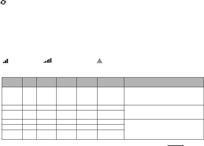
RatingsCompatibility Table 1: Communicator Ratings
Model GS2060-SM
GPRS only TL260-SM
Ethernet only TL260GS-SM
Ethernet & GPRS
POWER SUPPLY RATINGS
Input Voltage Nominal 12 VDC:
The panel Bell output shall be derated:
700mA - (Communicator mA) = (derated Bell output).
CURRENT CONSUMPTION
Standby Current
90mA @ 13.66V 100mA @ 13.65V 120mA @ 13.66V
Alarm (Transmitting) Current
400mA @ 12V
Operating Frequency
Quad band 850MHz, 900MHz, 1800MHz, 1900MHz
Typical Antenna Gain
2dBi
ENVIRONMENTAL SPECIFICATIONS
Operating Temperature 32°F - 120°F (0°C - 49°C)
Humidity 5% ~ 93% relative humidity, non-condensing
MECHANICAL SPECIFICATIONS
Board Dimensions (mm) 100 × 150 × 15 100 × 150 × 18 100 × 150 × 15
Weight (grams) with bracket 310 290 320

5
NOTE: Enter [*][8][Installer Code][900] at keypad to view the Panel Version number.
Products or components of products, which perform communications functions only shall comply with the
requirements applicable to communications equipment as specified in UL60950 or CAN CSA C22.2. No.
60950-1, Information Technology Equipment - Safety - Part 1: General Requirements. Where network inter-
faces are internal to the control unit or receiver, compliance to CAN CSA C22.2. No. 60950-1 is adequate. Such
components include, but are not limited to: hubs; routers; NIDs; Third party communications service providers;
DSL modems; and Cable modems.
Software Compatibility
The Communicator is compatible with the following ADT Pulse software:
• iControl Interactive.
• System Administrator.
ADT Pulse
NOTE: This application has not been investigated by UL/ULC and is not used on UL/ULC certified
installations.
The Communicator provides ADT Pulse Level 1, 2, and 3 monitoring and control via an RS-422 interface to an
external iHub. The default Keybus link speed is 115.2 KB and this option is programmable by the installer. All
life-safety events are encrypted and transmitted by the GPRS path to the central monitoring station (Level 1).
All life-style events are transmitted by the RS-422 link, using ITv2.0 protocol to the iHub, and then to remote the
iControl Servers (Level 2 and Level 3).
NOTE: iControl’s iHub is an interface device which connects to security panels, IP cameras, sensors,
Z-wave based home automation devices, etc. to deliver a host of advanced functionality.
NOTE: Life-style events are “non alarm” events. Life-safety events are “alarm” events.
There are three ADT Pulse levels, defined as follows:
•.L1: GPRS Remote Control of Arm/Disarm and notification for doors and windows. All life-safety and life-style
events are transmitted on the GPRS channel only.
•L2: Broadband with Z-Wave and L1. Life-safety events use GPRS channel. Life-style events use RS-422.
•L3: Broadband with L1, L2, and video. Life-safety events use GPRS channel. Life-style events use RS-422.
The following features are available with the RS-422 ADT Pulse Interface:
• Communicator faults can be transmitted.
• Panel communication errors are reported to the ADT iHub.
• Real time reporting of Zone status information to the ADT iControl Server.
• Remote update of the Communicator (flash upgrade).
• SMS incoming “wake up” for the GPRS channel.
• WEB login to request an incoming session with the Communicator.
• Zone Label Programming.
NOTE: Communicator buffers 1,000 date/time stamped Life-Style events to iHub as First In First Out (FIFO).
Encryption
The Communicator uses 128 Bit AES Encryption. Encryption can only be enabled from the monitoring station
receiver. Each receiver (Ethernet 1 and 2, GPRS 1 and 2) can independently have encryption enabled or dis-
abled. When encryption is enabled, the central station will configure the device to encrypt communications the
next time the Communicator module performs a communication to that receiver.
NOTE: Packets will start being encrypted only after the next event is sent to that receiver, or if the unit
is restarted.
Before leaving the installation site, the Communicator TL260-SM/TL260GS-SM Ethernet line shall be
connected via an APPROVED (acceptable to the local authorities) Network Interface Device (NID) (e.g.,
for UL Installations, U60950 listed NID). All wiring shall be performed according to the local electrical
codes.
This GPRS/Ethernet Communicator shall be installed by Service Persons only. (Service Person is defined as a per-
son having the appropriate technical training and experience necessary to be aware of hazards to which that person
may be exposed in performing a task and can also take measures to minimize the risks to that person or other per-
sons). The Communicator shall be installed and used within an environment that provides the pollution degree max
2, overvoltages category II, in non-hazardous, indoor locations only. This manual shall be used with the Installation
Manual of the panel which is connected to the GPRS/Ethernet Communicator. All instructions specified within the
panel manual must be observed.
All the local rules imposed by local electrical codes shall be observed and respected during installation.
Table 2: Compatible Receivers, and Panels
Communicator Receiver/
Panel Description
GS2060-SM
TL260-SM
TL260GS-SM
Receiver
• Sur-Gard System I Receiver, version 1.30+
• Sur-Gard System II Receiver, version 2.10+
• Sur-Gard SG-DRL3-IP, version 2.30+ (for Sur-Gard System III Receiver)
• Sur-Gard SG-DRL4-IP version 1.20+ (for Sur-Gard System IV Receiver)
Panel • Power Series PC1616, version 4.5+
• Power Series PC1832, version 4.5+
• Power Series PC1864, version 4.5+
PRE INSTALLATION CONFIGURATION
COMMUNICATOR INSTALLATION CONFIGURATION
6
Installing the Ethernet Cable
(TL260-SM/TL260GS-SM only)
A Category 5 (CAT 5) ethernet cable must be run from a source with Ethernet/Internet connectivity to the Com-
municator module, inside the Panel. The Communicator end of the cable must be terminated with an RJ45
plug, which will connect to the Communicator’s RJ45 jack after the Communicator is installed. All requirements
for installation of CAT5 ethernet cable must be observed for correct operation of the Communicator, including,
but not limited to, the following:
• Do NOT strip off cable sheathing more than required for proper termination.
• Do NOT kink/knot cable.
• Do NOT crush cable with cable ties.
• Do NOT untwist CAT5 pairs more than ½ in. (1.2cm).
• Do NOT splice cable.
• Do NOT bend cable at right angles or make any other sharp bends.
NOTE: CAT5 specification requires that any cable bend must have a minimum 2 in. (5 cm) bend radius.
Maximum length of CAT 5 cable is 328 ft. (100 m).
Running the RS-422 Cable
An RS-422 cable must be connected to the ADT iHub and cable run to the Communicator module inside the panel.
NOTE: Maximum cable length for RS-422 cable is 1,000 ft. (305 m).
At the ADT iHub, attach wires as follows:
1. Securely fasten the TX+ wire on the terminal block.
2. Securely fasten the TX- wire on the terminal block.
3. Install a 120
¼ W resistor between the RX + and RX- terminals at the iHub.
4. Securely fasten the RX+ wire on the terminal block.
5. Securely fasten the RX- wire on the terminal block.
6. Securely fasten the GND wire on the terminal block .
NOTE: The GND connection is optional, DSC recommends connecting the GND terminal at both ends.
7. Run the RS-422 Cable from the iHub to the Panel.
Inserting and Removing the SIM Card
1. Remove the front cover of the Panel to access SIM holder.
2. Remove power from the panel and disconnect the battery and telephone line.
3. On the SIM card holder push gently to slide the cover towards the Printed Circuit Board (PCB) antenna, as
indicated by the arrow on SIM holder, to OPEN. This will unlatch the SIM card holder on the side closest to
edge of the Communicator PCB. (See Figure 3).
4. Lift up the SIM card holder from the side that is not hinged.
NOTE: The SIM can be damaged by bending, or scratching contacts. Use caution when handling SIM cards.
5. Insert or remove the SIM card, noting the orientation of the notches on the SIM card and the SIM card holder.
6. When inserting a SIM card, insert the card in the proper orientation and gently push the SIM card holder
down and slide the holder as indicated by the arrow on SIM holder, to LOCK.
7. Reconnect the backup battery and telephone line, apply AC power to panel, and replace the panel cover.
Hardware Reset
The Communicator can be hardware reset by installing a jumper between Pins 4 and 5 on the AUDIO/
DEFAULT connector and restarting the Communicator. Installing jumper during normal operation has no effect.
Installing Communicator with PC1616/1832/1864 Panel
NOTE: Before installing Communicator or inserting/removing SIM, ensure that system power is OFF
and telephone line is disconnected.
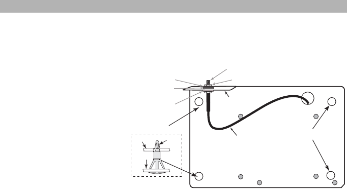
1. To assemble supplied mounting bracket, perform the following: (See Figure 1).
a. Remove the 4 white plastic
standoffs from the bag provided
with the Communicator kit.
b. Insert the 4 standoffs through
the back of the mounting
bracket, into the holes at each
corner. (The antenna mounting
tab should be facing away from
you).
c. Place the bracket on a flat,
solid surface. Hold the Commu-
nicator face up and orient the 4
holes on the Communicator
with the 4 standoffs protruding
from the bracket. Push the
Communicator firmly and
evenly onto the standoffs until it
is securely attached to the
mounting bracket.
d. Remove the panel front cover.
e.
TL260-SM/TL260GS-SM only
:
Remove and discard the circular knockout located in the top-right section of the panel. (This hole will be used
for connection of the supplied radio antenna).
f. TL260-SM/TL260GS-SM only: Connect the supplied 5” (12.7 cm) antenna cable to the radio, by passing
the connector through the hole on back of the mounting bracket to the Communicator board. Push the
antenna connector firmly into the socket on the GPRS radio. (See Figure 3).
2. Install the Communicator into the panel:
INSTALLING THE GSM/ETHERNET COMMUNICATOR IN PANEL
DG009344
Brass Washer
Nylon washer (flat)
Nylon Washer
with bushing
(thicker flat washer)
Brass nut
Antenna
Mounting Tab
Mounting
Holes
Mounting Holes
Antenna
Cable
Mounting Plate
for UA585
External Antenna
Screw Thread
Communicator
Board
Mounting
Plate
Stand Off
Figure 1 Communicator Mounting Bracket
7
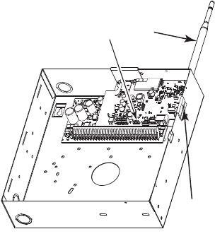
a. Attach one end of the PC-LINK cable to the panel PC-LINK header on the panel (red wire goes on Pin 1
of the panel PC-LINK header).
b. Insert the assembled Communicator into the panel.
NOTE: Ensure that the threaded antenna connection
point is visible through the knockout hole at the top
right of the panel.
c. TL260-SM/TL260GS-SM only: Place the nylon
washer with bushing (thick flat washer) onto the
threaded section of the antenna cable. Insert the
threaded section through the antenna mounting
knockout hole at top right of panel.
d. Place the second nylon washer (flat), followed by the
brass washer and the brass nut, onto the threaded
section of the cable, outside the panel. Tighten the
assembly by hand only. (Finger Tight - Do not over-
tighten the assembly).
e. Locate the screw hole on the right side wall of the
panel. See Figure 2 (screw). Line up the assembled
Communicator with the side wall of the panel and,
using the screw provided, secure the mounting
bracket to the panel.
f. Attach the other end of the PC-LINK cable to the
Communicator (black wire goes on Pin 1 of the Com-
municator).
g. TL260-SM/TL260GS-SM only: Using light pressure
(finger tight), attach the supplied 5” white quad band
whip antenna to the threaded antenna connection
point at top of the panel.
WARNING!
GS2060-SM/TL260-SM/TL260GS-SM MODULES ARE POWER LIMITED. DO NOT ROUTE ANY
WIRING OVER THE CIRCUIT BOARD. MAINTAIN AT LEAST 1IN. (25.4MM) SEPARATION BETWEEN
CIRCUIT BOARD AND WIRING. A MINIMUM OF ¼ IN. (7MM) SEPARATION MUST BE MAINTAINED AT
ALL POINTS BETWEEN NON-POWER LIMITED WIRING AND POWER LIMITED WIRING.
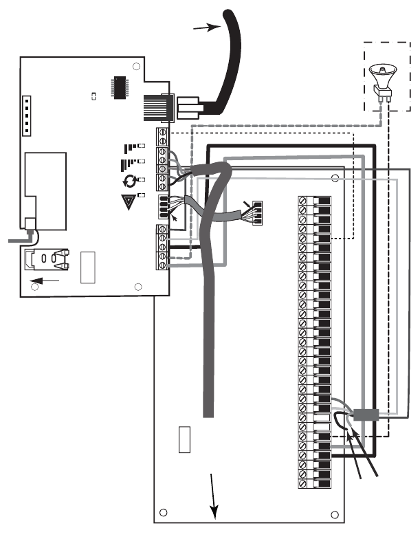
3.To electrically connect the Communicator to the panel, perform the following steps (See Figure 3).
a. Disconnect both AC power and battery connections from the panel.
Module Power Connection
b. Attach a wire from the Communicator’s left PWR terminal to the panel’s BELL+ terminal.
NOTE: For ULC Commercial Fire Monitoring applications: Do NOT connect any devices on the
Bell + terminal other than the Communicator.
c. Attach a wire from the Communicator’s GND terminal (beside PWR) to the panel’s AUX - terminal.
d. Attach a wire from the Communicator’s SHLD terminal to the panel’s EGND terminal.
(Protective earth ground).
(Optional) External Bell/Siren Connection
e. Attach a wire from the Communicator’s right PWR terminal to the positive (+) terminal on the Bell/Siren.
f. Attach the panel’s BELL
-
terminal to the negative (
-
) terminal on the Bell/Siren.
NOTE: If a Bell/Siren is not used, install the 1K
½W 5% resistor (Brown, Black, Red, Gold) (supplied
with the panel) between the panel’s Bell + and Bell
-
terminals, then only wire the BELL + to the PWR
terminal on the Communicator.
g. Confirm that the SIM card is inserted in the holder and locked.
h. Insert the PC-LINK connector into the Communicator’s PC-LINK socket. (Black wire on Pin 1 on the
Communicator).
DG009545
PC-Link
Cable Connector
(screw)
Quad band
Whip Antenna
PC1616/1832/1864
GSM Radio
RJ-45
UA585
Use light pressure
to attach antenna
Finger Tight only.
Figure 2 PC1616/1832/1864 Control Panel
8
Keybus Connection for ADT Pulse
4. Install the Keybus cable as follows:
WARNING: DO NOT CONNECT KEYBUS RED OR BLK WIRES TO THE PANEL OR
THE COMMUNICATOR TERMINAL BLOCKS.
a. Attach a wire from the Communicator YEL terminal to the panel YEL terminal.
b. Attach a wire from the Communicator GRN terminal to the panel GRN terminal.
RS-422 Connection for ADT Pulse
At the Communicator inside the Panel, attach the previously run cable as follows:
1. Securely fasten the TX+ wire to RX+ on the terminal block.
2. Securely fasten the TX- wire to RX- on the terminal block.
3. Securely fasten the RX+ wire to TX+ on the terminal block.
4. Securely fasten the RX- wire to TX- on the terminal block.
5. Securely fasten the GND wire on the terminal block .
NOTE: The GND connection is optional, DSC recommends connecting GND at both ends of cable.
DG009546
AUDIO/ DEFAULT
DSC
UA585
PC-LINK
PC-LINK
GND
TL260-SM
TL260GS-SM
GS2060-SM
AC
AC Z1 COM Z2 Z3 COM Z4 Z5 COM Z6 Z7 COM Z8
AUX+
BELL +
PGM1 PGM3
RING
T-1
PC1616/1832/1864
GSM Radio
RX 1 & RX 2
+
-
UA503
1
To ex t e r n al antenna
Input Ratings from Bell +:
+11.1V ~ +12.6 VDC
100mA standby; 400mA alarm
DSC Panel min power requirements:
- 16 VAC 40 VA transformer;
- 12 VDC 7Ah battery
+
-
External Bell/Siren
Black
Black
Jumper pins 4 and 5
to reset.
L
o
c
k
1
GRN
RS-422
To ADT iHub
Maximum cable length
305 m (1,000 ft)
From NID
(GS2060-SM/TL260GS-SM)
Use only CAT5
Supervised
RJ-45
YEL
COM
PWR
GRN
YEL
TIP
R-1
BLK
RED
AUX -
BELL -
EGND
Do NOT
connect
Red or Black
Keybus wires!
TX+
GND
TX-
RX+
RX-
SHLD
Green
Yellow
SIM
Network Link
(TL260-SM only)
YELLOW
XX
PGM2 PGM4
Maximum cable length
100 m (328 ft)
PWR
REV 0 1
Figure 3 Communicator Wiring Diagram

9
Install Network Cable (TL260-SM/TL260GS-SM only)
Route the CAT 5 Ethernet cable through back of the panel and plug it into the Communicator’s RJ45 jack.
Before leaving the premises the Ethernet communication lines must first be connected to an approved
(acceptable to local authorities) type NID, (UL installations, UL 60950 listed NID, for ULC installations
CAN/CSA C22.2. No. 60950-1 Certified NID). All wiring shall be performed according to the local
electrical codes.
6. Perform the following steps for initial power on of the panel with Communicator installed:
a. Reconnect the AC power, telephone line, and battery + connector to the panel. (the Communicator and
Panel will power up together).
b. Observe that the Communicator’s red and yellow LEDs are flashing together while it initializes. The red
and yellow LEDs will continue to flash until the Communicator has successfully communicated to all pro-
grammed receivers. If this is the first time the Communicator has been powered up in the panel, the mod-
ule will initiate communication to request programming remotely.
NOTE: Initialization may take several minutes to complete. red and yellow LEDs will flash together dur-
ing initialization. Do not continue to next step until the red and yellow LEDs have stopped flashing. (If
only the yellow LED is flashing, there is a Communicator trouble and the Green LEDs are not valid for
Communicator Placement Test). Correct trouble indicated by flashes on yellow LED before continuing.
(See Table 5 for troubleshooting assistance).
7. GS2060-SM/TL260GS-SM only: Perform the Communicator Placement Test on page 10.
8. Mount the Panel in final location indicated by placement test.
Domain Name Service (DNS) programming is not permitted in UL/ULC listed systems.
Keypad Data Display
•Section-Toggle Options: The number is displayed when Toggle is ON, the number is not displayed when
Toggle is OFF. (e.g., Toggle Options displays: [
--
3
--
6
--
]. Options 3 and 6 are ON, all others are OFF). Press-
ing keys 1 through 8 will alternately turn the Toggle ON and OFF.
•HEX/Decimal Data: Values that are provided with two defaults, separated by a “/” character, use the format:
hexadecimal followed by decimal equivalent (e.g., Default [0BF5/3061]). Hexadecimal numbers are shown,
with all leading zeroes, to the full field length defined for the number.
Entering HEX values at keypad
To enter HEX values at the keypad, you must press the
*
key before entering the HEX value. (e.g., to enter “
C
” at
the keypad, press
[*][3]
.
Entering ASCII Characters at keypad
1. Press [*] and use scroll buttons [<] [>] to display “ASCII Entry” on the LCD screen.
2. Press [*] to select ASCII entry mode.
3. Use the [<] [>] scroll keys to display the character you want and press [*] to save and exit ASCII.
4. Repeat the steps above to enter another ASCII character.
PC1616/1832/1864 Initial Programming
Perform the following steps to ensure that the Communicator and the Panel work together as intended.
These Sections must be programmed at the panel keypad. Enter
[*][8][Installer Code][Section Number]
. Record
any values that are modified from their default, in the appropriate Worksheets for the Panel or Communicator.
1. In Panel Section [167] program 060 (seconds).
2. In Panel Section [382] set Option [5] ON
NOTE: If this option is OFF, the yellow status LED on the Communicator will indicate ‘Panel Supervision Trou-
ble’ (2 flashes) and the unit can not be programmed via the PC-LINK cable.
3. In Panel Section [383] [2] set Option [7] ON.
4. In Panel Section [383] [2] set Option [8] ON for CID, or OFF for SIA.
5. A valid Account Number must be entered in Communicator Section [851][021]. See Programming Section.
NOTE: DSC recommends using the same Account Number for Panel and Communicator.
6. In Panel Sections [301], [302], and [303], program the central station telephone number that will be used for
the GPRS/Ethernet Communicator. Valid entries are:
a. A valid telephone number; signals will be routed to the central station using the Public Switched Tele-
phone Network (PSTN).
b. DCAA (Receiver 0); signals will be routed to GPRS/Ethernet Receivers 1 - 4 depending on programming
Toggle Options in Communicator Section [851][006].
c. Panel Section [301] sets the Primary communication path, and may be configured as either PSTN or
Communicator routing. Panel Section [302] is redundant, and Panel Section [303] is the backup tele-
phone number for Panel Section [301]. Refer to the Panel manual for additional information.
NOTE: The leading digit ‘D’ (dial tone detection) in the telephone number is pre-programmed.
7. In Panel Section [350], program the communication format as: CID (03) or SIA FSK (04).
NOTE: If any of the Panel telephone numbers have been set to DCAA, section [350] must be set to (04).
8. In Panel Sections [351] - [376], program the Communicator call direction options. Refer to the Panel Installa-
tion Manual for details on setting these options.
9. In Panel Section [401] set Toggle Option [2] ‘User Enable DLS’ to ON in order to perform panel DLS session
through GPRS or Ethernet.
NOTE: Before leaving the premises, the installer should verify all programmed communications paths.
See Programming Options Section [851][901] to send immediate test transmissions.
Communicator Troubles displayed on a PC1616/1832/1864
The General System trouble is the only trouble that will appear on the keypad Liquid Crystal Display (LCD)
when encountered by a Communicator installed in a PC1616/1832/1864. For more information about the trou-
ble on the Communicator module refer to the panel event buffer. Log entry will show Fault or Restore for each
of the following events:
INITIAL PANEL PROGRAMMING
10
•T-LINK Network Fault/Restore: This log will occur for the following trouble conditions: SIM Lock Trouble,
GSM Trouble, Ethernet Trouble, or Connect24 Configuration Trouble.
•T-LINK Receiver Trouble/Restore: This log will occur for the following trouble conditions: Receiver Not
Available Trouble, Receiver Supervision Trouble, or Failure to Communicate (FTC) Trouble.
•T-LINK Comm. Fault/Restore: This log will occur when the panel loses communications with the Communi-
cator and will clear when communications is restored.
To confirm that the GPRS antenna location is suitable for radio operation, perform this test as follows:
NOTE: You may need to relocate the Panel or install an optional extension antenna during this proce-
dure, if radio signal strength is too low.
1. Confirm that the yellow LED on the Communicator is not flashing. A flashing yellow LED indicates trouble on
the Communicator. See Table 5 to troubleshoot and correct the cause of this trouble before continuing to
the next step.
2. Observe the strength of the radio signal on the yellow LED and the 2 green LEDs on the Communicator meet or
exceed the minimum signal level requirement. Minimum Signal Level: The yellow LED is OFF and the Green LED
1 (furthest from the yellow LED) is ON. (i.e., not flashing) for the panel location to be acceptable. See table for
Radio Signal Strength on page 11 for interpretation of receiver signal strength on LEDs.
NOTE: If the required signal strength is too low with the panel in its current location, the panel must be
relocated or an external antenna is required.
a. If required, the following GSM extension antenna kits are available to the installer:
• GS15-ANTQ - 4.57m (15’) Internal Antenna Extension Kit (suitable for interior mounting only).
• GS25-ANTQ - 7.62m (25’) External Antenna Extension Kit (suitable for exterior mounting only).
• GS50-ANTQ - 15.24m (50’) External Antenna Extension Kit (suitable for exterior mounting only).
Specific instructions for the installation of the extension antenna are included with the kit. Observe all the elec-
trical safety instructions regarding the installation of the antenna. All the wiring of the equipment shall be fully
compliant with the local rules and regulations.
3. If required, install the antenna extension and perform the following steps to determine the best location for
placement of the antenna :
a. Disconnect the white whip antenna from the panel.
b. Attach one end of the antenna extension cable to the threaded antenna connector on the panel and the
other end to the external antenna.
4. Move the extension antenna to various locations while observing the two Green LEDs on the panel.
a. Continue to reposition the extension antenna until you receive an acceptable (minimum one green LED
ON solid) signal strength.
NOTE: Minimum strength is: green LED 1 flashing and yellow LED OFF. If green LED 1 is flash-
ing, relocation should be considered.
b. Mount the supplied antenna extension bracket at the location that provided the best signal strength.
5. Alternately, you can reposition the Panel to improve signal strength. Dismount the panel and move it to
another location to achieve the required signal strength. If the Panel is relocated to improve signal strength,
mount it in the new location.
6. When final Panel/antenna location is determined, continue installation at Initial Panel Programming section.
The Communicator has 4 onboard LED indicators. These include 1 yellow trouble LED, 1 red Network Connec-
tion Status LED, and 2 green Signal Strength LEDs. The LED meaning is described in this Section.
Yellow Trouble LED
This yellow LED will flash to indicate a trouble on the unit. The number of flashes indicates the type of trouble.
See the table below for the coded flashes and the conditions which will activate the Trouble Status LED.
NOTE: Only the highest priority trouble (1 Flash is highest priority) is indicated. When this trouble is
restored, the next highest trouble will indicate, if present. This will continue until all troubles have been
cleared. (yellow LED OFF).
The following paragraphs describe the conditions associated with the trouble indicated:
Panel Supervision Trouble (2 Flashes)
This trouble will be indicated when communication between the Communicator module and the Panel fails. If
the module can not communicate with the Panel (e.g., loss of power to the panel) the Communicator will send
the ‘Panel Absent Trouble Event’ message to the central station receiver. When communication returns, a
‘Panel Absent Restore Event’ is sent by the Communicator to the central station receiver. The reporting codes
are ET0001 for Trouble and ER0001 for Restore. The panel absent event always uses the primary receiver
account code when communicating to the central station.
NOTE: The Panel Supervision Trouble/Restore are internally generated events by the Communicator.
They are the only internal events; all other events are generated by the panel. Trouble is generated if
the Communicator misses 6 Polls. Trouble is restored on receipt of first Poll from the Panel.
COMMUNICATOR PLACEMENT TEST
COMMUNICATOR STATUS LEDS
Table 3: Yellow Trouble Status LED
# of
Flashes Trouble # of
Flashes Trouble
2 Panel Supervision Trouble 8 Receiver Supervision Trouble
4 SIM Lock Trouble 9 FTC Trouble
5 GSM Trouble 10 Configuration Failure
6 Ethernet Trouble 11 Remote Programming
7 Receiver Not Available Trouble 12 Module Configuration Trouble
11
SIM Lock Trouble (4 Flashes)
This trouble will signify that the SIM lock feature has been enabled and the unit has not been programmed with
the correct PIN for the SIM card.
GSM Trouble (5 Flashes)
This trouble is indicated for any of the following 4 conditions:
1. Radio Failure: Trouble is indicated after 8 failed attempts to communicate with the GPRS radio.
2. SIM Failure:Trouble is indicated after 10 failed +CPIN commands.
3. GPRS Network Trouble: Trouble is indicated for loss of the registration to the network provider. (3 consecu-
tive init or refresh failures, failure to connect to an APN, failure to open a socket, total error count in cyclic
command = 20, or on receiving an MSDI (1/2), (7/8/14). Trouble will clear after init and cyclic commands suc-
ceed and MIPCALL and MIPOPEN commands succeed.
4.
Insufficient Signal Strength
: Trouble is indicated if
calculated
average
signal strength is too low. (Both green
LEDs are OFF). Trouble will clear when the calculated average signal strength is above minimum (i.e., > CSQ 5).
Ethernet Trouble (6 Flashes)
This trouble is indicated when Ethernet link between the transmitter and the local switch or router is absent.
This trouble will also be indicated if the unit fails to get Dynamic Host Control Protocol (DHCP) settings from the
DHCP server. (Not active if Ethernet Receivers are not programmed).
Receiver Not Available (7 Flashes)
This trouble is indicated if the unit is not able to successfully initialize with any of the programmed receivers.
Unprogrammed receivers are excluded. This trouble is also indicated if the GPRS receiver APNs have not been
programmed in Sections [205] and [215].
Receiver Supervision Trouble (8 Flashes)
This trouble is indicated when receiver supervision is enabled and communication between the Communicator
module and the receiver fails. Trouble is indicated if Ethernet 1 is supervised and does not receive a heartbeat
from the receiver or if GPRS is supervised and the unit does not receive an acknowledgment to 4 heartbeats
sent to the receiver.
FTC Trouble (9 Flashes)
This trouble is indicated when the unit fails to communicate module events to the central station. Trouble is dis-
played after the unit has exhausted all communications attempts to all programmed receivers for events gener-
ated by the Communicator.
Configuration Failure (10 Flashes)
This trouble is indicated when the unit fails to receive remote programming.
Remote Programming (11 Flashes)
This trouble is indicated during a remote firmware upgrade. Indicates that a remote firmware update is in prog-
ress over GPRS/Ethernet. Trouble will clear automatically when update completes successfully.
Module Configuration Trouble (12 Flashes)
This trouble is indicated when the System Account Code or the Receiver Account have not been programmed.
Disabled receivers are excluded.
Red Network Connection Status LED
(
TL260-SM/TL260GS-SM
)
BLINKING: Indicates communications in progress.
• Once quickly for outgoing Ethernet transmission.
• Twice quickly to indicate incoming Ethernet ACK/NACK.
OFF: This is the normal state of the Red Network Connection Status LED. There are no network connection
issues present.
ON
: There is a problem with the Ethernet or the GPRS network connection. LED will be ON if any of the following occur:
• Ethernet cable is not connected,
• DHCP configuration times out,
• Unit fails to get an IP address from the GPRS network, or
• GPRS connection has been reset.
(Green LED 1) (Green LED 2) and (Yellow LED) Signal Strength
NOTE: If the yellow LED is flashing, Signal Strength in table below is not valid.
See
Table 5
for troubleshooting flashing yellow LED.
NOTE: The Communicator will indicate GSM Trouble (yellow LED = 5 flashes) if the average CSQ Level
is 5 or less. The Communicator Signal Strength can be viewed remotely.
Table 4: Radio Signal Strength
Signal
Strength CSQ
Level Yellow
LED Green
Led 2 Green
LED 1 Signal Level
dBm Action Required
No Signal 0 ON OFF OFF -108.8
• Check all antenna connections.
• Confirm GPRS service is active in area.
• Relocate Panel or install external
antenna.
1 Bar 1 - 4 ON OFF Flashing -108 ~ -103 Relocate Panel or install external antenna
if Yellow Trouble LED has:
5 flashes.
2 Bars 5 - 6 OFF
See Note OFF Flashing -102 ~ -99
3 Bars 7 - 10 OFF OFF ON -98 ~ -91
Location is OK
. GPRS Signal Strength is
greater than CSQ 5.
4 Bars 11-13 OFF Flashing ON -90 ~ -85
5 Bars 14 + OFF ON ON -84 and
higher

12
Network Activity LEDs (Red and Green)
(TL260GS-SM only)
•Ethernet Activity: Red LED will blink quickly once for Ethernet Transmit, or twice for Ethernet Receive.
•GPRS Activity: Green LED 2 will blink quickly once for GPRS Transmit, or twice for GPRS Receive.
Network Link LED (Yellow)
(TL260-SM only) See Figure 3 for location of LED.
The TL260-SM uses an additional Link LED on the board. LED is lit to indicate an active Ethernet connection.
.
Factory Defaults Reset
You can reset the programming options for the Communicator to the factory settings by installing the hardware
jumper. Perform the following steps to reset the Communicator:
NOTE: A jumper is required on AUDIO/DEFAULT pins 4 and 5 to reset the hardware values.
1. Remove Panel front cover.
2. Locate the AUDIO/DEFAULT 5 pin connector on the Communicator board. (See Figure 3).
3. Apply a jumper to short the hardware default pins 4 and 5.
4. Remove AC and DC power from the panel and then reapply power to the Panel. Wait until the two green
LEDs on the Communicator begin flashing rapidly.
5. Remove the jumper from the hardware default pins 4 and 5. (Green LEDs will stop flashing).
6. Replace the Panel cover.
NOTE: Your Communicator has now been reset to the factory default values.
Firmware Update
The firmware of the device can be updated over GPRS or Ethernet (Remote or Local updating):
• When the firmware update begins, all 4 LEDs are ON.
• During the firmware update process, the LEDs will be cycled individually in a chaser pattern.
• After a successful update, the unit will automatically restart.
• Should the update fail, all 4 LEDs will flash ON, then OFF together at 1 second intervals.
NOTE: If the firmware update fails, restart the Communicator by cycling Power. For persistent update
failures, contact your dealer. For UL/ULC listed installations, only local firmware updates are allowed.
COMMUNICATOR RESET / UPDATE

13
APPENDIX A: COMMUNICATOR TROUBLESHOOTING
Table 5: Trouble LED indications
Trouble
indication Possible
Causes Trouble Possible Solution
No Indication No Power
• Check the power connections between the Panel and the Communicator.
• Confirm PC-LINK cable is properly installed between communicator and panel.
Yellow LED –
ON Solid Insufficient
Signal Strength
• Confirm that GPRS network service is active in your area.
• Ensure the antenna is securely connected to the radio. Check antenna stub cable
is securely connected to the radio.
• If an external antenna is used ensure the antenna is securely screwed on to the
antenna cable connector. Check external antenna for damage or open/short.
Trouble LED –
2 Flashes
Panel
Supervision
Trouble
• Check Section [382]Toggle Option[5] is ON.(GPRS/Ethernet Module Enabled)
• Ensure the PC-LINK cable between the Panel and Communicator is connected
properly (not reversed) and is securely in place.
Yellow LED -
4 Flashes Lockout
Trouble
• The SIM card has incorrect PIN programmed or has a PIN that the module does
not recognize. Replace the SIM card.
Yellow LED –
5 Flashes GSM Trouble
• Confirm that GPRS service is available and active in your area.
• Check all antenna connections.
•Ensure
average
radio signal strength is CSQ
6
or higher. (See Table 4 ).
• Ensure the SIM card is properly inserted into the SIM card holder.
• Ensure the SIM card has been activated. (Could take up to 24 hrs after install).
• If this trouble persists, you must relocate the Panel (and Communicator) or install
an external antenna extension kit.
Yellow LED –
6 Flashes Ethernet
Trouble
• Check with your ISP to confirm Internet service is active in your area.
• Ensure your Ethernet cable is securely inserted into the RJ45 jack of the Commu-
nicator and the Hub/Router/ Switch.
• Check the link light on the Hub/Router/ Switch is ON . If link light is OFF, try restart-
ing the Hub/Router/ Switch.
• If DHCP is used, ensure that the unit has an assigned IP address from the server.
In Panel Section [851] [992] verify a valid IP address is programmed. If not, con-
tact the Network administrator.
• If problem persists, replace the Ethernet cable and RJ45 connector.
Yellow LED –
7 Flashes Receiver Not
Available
• Ensure that the Ethernet path has internet connectivity.
• If you are using a static IP address make sure the gateway and subnet mask are
entered correctly.
• If the network has a firewall, ensure the network has the programmed
outgoing ports open (Default UDP Port 3060 and Port 3065).
• Ensure that all the receivers are programmed for DHCP or have the proper IP
address and port number.
• Ensure the GPRS Receiver APNs have been programmed with the Access Point
Name provided by your GPRS provider.
Yellow LED –
8 Flashes
Receiver
Supervision
Trouble
• This trouble is indicated when supervision is enabled and the unit is not able to
successfully communicate with the receiver.
• If this trouble persists, contact your central station.
Yellow LED -
9 Flashes FTC Trouble
• The unit has exhausted all communications attempts to all programmed receiver
for events generated by the Communicator.
• Restart the system, if trouble persists, contact your dealer.
Yellow LED –
10 Flashes
Connect24
Configuration
Failure
• This trouble is indicated when the SIM is active but there is no programming for
the unit.
• Ensure a profile has been programmed in Connect 24 for the SIM.
• You can confirm your programming by calling the Connect 24 VRU, or by logging
into the Connect24 VRU web site.
Yellow LED –
11 Flashes Remote
Programming
• The LEDs will flash when a remote firmware upgrade is in progress over Ethernet
or GPRS. The LEDs will extinguish when update is complete.
• The LEDs will flash to indicate a remote programming session is active over
Ethernet or GPRS. The LEDs will extinguish when the session terminates.
Yellow LED –
12 Flashes
Module
Configuration
Trouble
This indication appears when Section [021] System Account Code or
Section [101]; [111]; [201]; and [211] Receiver Account Code have not been pro-
grammed. Ensure that a valid account code has been entered in these Sections.
All LEDs flash-
ing together Boot Loader
Failed
Disconnect power, then reconnect power to the Communicator module.
Red and Yellow
LEDs flashing
together
Initialization
Sequence
The unit is still initializing please wait while the unit gets its programming and estab-
lishes a connection to all programmed receivers.
Note that this process may take several minutes.
Only Green
LEDs flashing Hardware
Default Jumper
The hardware default jumper must be removed. See Figure 3.

14
The Programming Sections in this document are accessed via panel Section for Ethernet/GPRS Programming.
Enter: [*][8][installer code][851][###], Where ### is the 3 digit Section number referenced in this document.
The Programming Worksheets at the end of this document can be used to record the new values when pro-
gramming changes have been made from the default values. Default values are provided for each Section.
Programming Sections cannot be modified from the keypad. Installers may review/record programming Options
at the keypad.
NOTE: Ethernet/GPRS Programming Sections accessed through the keypad are for display purposes
only. Configuration changes must be done remotely. Specified panel Sections must be configured for
proper operation of the Communicator and the Panel.
System Options
[001] Ethernet IP Address
Default (000.000.000.000)
Enter the IP address of the Communicator. Ensure that the IP address is unique to your Communicator on the local
network. Format is 4 fields, each field is a 3 digit decimal number. Valid range: 000-255. If an IP address is pro-
grammed in this Section, the unit will operate with Static IP (DHCP disabled). Sections [002] and [003] must also be
programmed when using Static IP addresses.
NOTE: Default for this Section is Dynamic Host Configuration Protocol (DHCP) enabled. When enabled,
the DHCP Server will set values for: IP Address [001], Subnet Mask [002], and Gateway [003]. Program-
ming an IP address in this Section will disable DHCP (Static IP).
[002] Ethernet IP Subnet Mask
Default (255.255.255.000)
Enter the Ethernet IP Subnet Mask of the dual Communicator. Format is 4 fields, each field is a 3 digit decimal
number. Valid range: 000-255.
NOTE: If DHCP is enabled, the DHCP Server will assign the subnet mask for this Section and the
programmed value will be ignored.
[003] Ethernet Gateway IP Address
Default (000.000.000.000)
Enter the Ethernet Gateway IP address of the Communicator. The gateway IP address is required when a router is
used on the local network to reach the destination IP address specified in Section [001]. Format is 4 fields, each
field is a 3 digit decimal number. Valid range: 000-255.
NOTE: If DHCP is enabled, the DHCP Server will assign the Gateway IP address for this Section and the
programmed value will be ignored.
[004] Receiver Supervision Interval
Default (0087/135)
When receiver supervision is enabled (ON) in Section [005] Toggle Option [3], the unit sends heartbeats to Ethernet
Receiver 1 or GPRS Receiver 1 to test the communications path. Use this Section to set the interval time (in sec-
onds) when heartbeats will be sent. Valid range 000
A
-FFFF seconds. If the programmed value is less than
(000A/10) seconds, supervision is disabled.
•Receiver Window: This is the supervision timeout that must be configured at the central station receiver.
•Recommended Values: This is the recommended heartbeat interval that should be programmed into the
Communicator.
• For ULC passive systems (not using heartbeat supervision), the Daily test transmission must be enabled
over each available communication channel Sections [125] and [225]. When programming with Connect24,
the recommended intervals will be programmed automatically when the required window is selected.
[005] System Toggle Options
[1] Ethernet Receiver 1 Supervised
Default (OFF) (TL260-SM/TL260GS-SM only).
ON: Ethernet Receiver 1 will be supervised and heartbeats will be sent to Ethernet Receiver 1 based on the
supervision interval programmed in Section [004].
OFF: Ethernet Receiver 1 will not be supervised. When disabled, heartbeat 1 is sent to the Ethernet receiver
once every hour, regardless of supervision type (heartbeat 1 or 2). The heartbeat is resent every 5 seconds until
ACK. If no event or heartbeat ACK is received after (Receiver Supervision Interval + 75 seconds), Supervisory
trouble is indicated.
NOTE: Ethernet Receiver 2 can not be supervised.
[2] GPRS Receiver 1 Supervised
Default (OFF)
ON: GPRS Receiver 1 will be supervised and heartbeats will be sent to GPRS Receiver 1 based on the super-
vision interval programmed in Section [004]. If ACK to heartbeat is not received, it is retransmitted every 5 sec-
onds. Failure to ACK 2 consecutive heartbeats will reset the radio.
COMMUNICATOR PROGRAMMING SECTIONS
Table 6: Supervision Intervals for UL/ULC
Jurisdiction Receiver Window
(Timeout) Recommended Supervision Interval
UL Commercial Burglary 200 seconds (0087/135) seconds
UL Residential Fire 30 days Panel Test Transmission
UL Residential Burglary 30 days Panel Test Transmission
ULC Commercial Burglary Active 180 seconds (005A/90) seconds
ULC Commercial Burglary Passive 24 hours Panel Test Transmission
ULC Commercial Fire Active 180 seconds (0073/115) seconds
ULC Commercial Fire Passive 24 hours Panel Test Transmission
15
OFF: GPRS Receiver 1 will not be supervised. When disabled, heartbeat is not sent to the receiver.
NOTE: GPRS Receiver 2 can not be supervised.
[3] Supervision Type
Default (OFF)
ON: Heartbeat 1 (Commercial Supervision). This supervision type is suitable for applications where swap detec-
tion is required on the supervisory packet.
OFF: Heartbeat 2 (Residential Supervision). This supervision type is suitable for applications where supervision
of the communication path to the receiver is required. (no swap detection).
NOTE: Commercial supervision is more data intensive than residential supervision and should only be
used when required to meet the approval for the installation.
[4] GSM Primary
Default (OFF - TL260-SM/TL260GS-SM) (ON - GS2060-SM)
ON: GPRS channel is the primary path. Ethernet channel is the secondary path, if it exists.
OFF: Ethernet channel is the primary path in a dual Communicator. GPRS channel is the secondary path.
[5] Redundant Communications
Default (OFF) (TL260GS-SM only)
ON
: Events will be communicated to Ethernet Receiver 1 and GPRS Receiver 1 at the same time. Events will be
communicated to Ethernet Receiver 2 and GPRS Receiver 2 at the same time. As long as the event is successfully
communicated to 1 of the 2 paths (Ethernet or GPRS) the Communicator will move on to the next event.
NOTE: Do not configure Ethernet Receiver 1 and GPRS Receiver 1 to communicate using a common
receiver configuration (i.e., identical Receiver IP address and Receiver Remote Port).
OFF: Events will be communicated to the receivers individually.
NOTE: Toggle should be OFF when guaranteed message delivery to both receivers is required.
[6] Remote Firmware Upgrade
Default (ON)
ON: The Communicator module firmware can be remotely upgraded using the Ethernet/GPRS paths.
OFF
: The Communicator module firmware can not be remotely upgraded. Local firmware upgrade is still possible.
[7] Alternate Test Transmissions Default (OFF).
ON: When the periodic test transmission interval occurs, the test transmission will alternate between being sent
to the primary and secondary receivers with each test transmission interval.
OFF: When the periodic test transmission interval occurs, the test transmission will be sent to the programmed
receivers, based on the settings of the periodic test transmission reporting codes.
[8] GSM Low Signal Trouble. Default (OFF).
[006] System Toggle Options 2
[1] Ethernet 1 Receiver Enabled. Default (ON) (OFF for GS2060-SM).
ON: Ethernet Receiver 1 is enabled.
OFF: Ethernet Receiver 1 is disabled.
[2] Ethernet 2 Receiver Enabled. Default (ON) (OFF for GS2060-SM).
ON: Ethernet Receiver 2 is enabled.
OFF: Ethernet Receiver 2 is disabled.
[3] Reserved. (OFF).
[4] GPRS 1 Receiver Enabled. Default (ON).
ON: GPRS Receiver 1 is enabled.
OFF: GPRS Receiver 1 is disabled.
[5] GPRS 2 Receiver Enabled. Default (ON).
ON: GPRS Receiver 2 is enabled.
OFF: GPRS Receiver 2 is disabled.
[6] Reserved (OFF).
[7] DLS Over GPRS. Default (ON).
NOTE: Program this toggle as OFF if you want to completely disable DLS from using the GPRS path.
ON: DLS is enabled on the GPRS path.
OFF: DLS is disabled on the GPRS path.
NOTE: If this Toggle is OFF, DLS sessions will occur on the Ethernet path only, regardless of Primary
Path set in Section [005] Toggle Option [4]. If it is ON then the Communicator will connect to the Primary
path first for DLS and if the session fails, the Secondary path will be used.
[8] Interactive over GPRS. Default (ON).
[007] DNS Server IP 1
Default (000.000.000.000)
Programming this Section is not permitted on a UL/ULC listed system.
Enter the IP address for DNS Server 1. Format is 4 fields, each field is a 3 digit decimal. Valid range: 000-255.
NOTE: If no value is programmed and DHCP is used, the DHCP Server will configure the address. If an
address is programmed and DHCP is used, the address that you program will be used instead of the
DHCP address.

16
[008] DNS Server IP 2
Programming this Section is not permitted on a UL/ULC listed system.
Default (000.000.000.000)
Enter the IP address for DNS Server 2. Format is 4 fields, each field is a 3 digit decimal. Valid range: 000-255.
NOTE: If no value is programmed and DHCP is used, the DHCP Server will assign this value. If an
address is programmed and DHCP is used, the address that you program will be used instead of the
DHCP address.
Programming Options
[011] Installer Code
Default (CAFE)
Program your installer code for this Communicator module. The installer code will be required when programming
the Communicator module. Valid range: 0000 - FFFF.
[012] DLS Incoming Port
Default (0BF6/3062)
The DLS Incoming Local Port (listening port) is the port DLS IV will use when connecting to the Communicator. If a
router or gateway is used, it must be programmed with a Transmission Control Protocol (TCP) port forward for this
port to the Communicator module IP address. Valid range: 0000-FFFF.
[013] DLS Outgoing Port
Default (0BFA/3066)
The DLS Outgoing Port is used for outgoing session to DLS IV after an SMS request has been sent to the Commu-
nicator. Use this Section to set the value of the local outgoing port. The value must be changed if the Communicator
is located behind a firewall and must be assigned a particular port number, as determined by your network adminis-
trator. In most cases, changing the default value or configuring your firewall with this port is not required.
Valid range: 0000-FFFF.
NOTE: If Section [006] Toggle Option [7] is ON. DLS will use the Primary path for session. If Section
[006] Toggle Option [7] is OFF DLS will use the Ethernet path, if available.
[020] Time Zone
Default (00)
Use Offset Hours column to find your local time zone offset from GMT/UTC. Record the two digit HEX value
from the HEX column on same row. Program this HEX value as your Time Zone. Valid range is 00 - FF.
Table 7: Time Zone Offset
HEX Offset
Hours Std
Abbrev Location HEX Offset
Hours Std
Abbrev Location
01 -12 BIT Baker Island Time 47 +5.5 IST Indian Standard Time
05 -11 NUT Niue Time 48 +5.75 NPT Nepal Time
SST Somoa Standard Time
49 +6
XJT Xinjiang Standard Time
09 -10
HAST Hawaii-Aleutian Standard Time EKST East Kazakhstan Standard Time
THAT Tahiti Time LKT Sri Lanka Time
TKT Tokelau Time VOST Vostok Time
CKT Cook Island Time OMSK Omsk Standard Time
0B -9.5 MIT Marquesas Island Time NOVT Novosibirsk Time
0D -9 AKST Alaska Standard Time BTT Bhutan Time
GIT Gambier Island Time BIOT British Indian Ocean Time
11 -8
PST Pacific Standard Time 4B +6.5 CCT Cococ Islands Time
PST Pitcarirn Standard Time MMT Myanmar Time
CIST Clipperton Island Standard Time
4D +7
CXT Christmas Island Time
15 -7 MST Mountain Standard Time KOVT Khovd Time
19 -6
CST Central Standard Time KRAT Krasnoyarsk Time
GALT Galapagos Time WIB Waktu Indonesia Bagian Barat
PIT Peter Island Time ICT Indochina Time
EAST Easter Island Standard Time BDT Bangladesh Standard Time

17
1D -5
EST Eastern Standard Time
51 +8
AWST Australian Western Standard Time
COT Colombia Time CST China Standard Time
ECT Ecuador Time HKST Hong Kong Standard Time
PET Peru Time WITA Waktu Indonesia Bagian Tengah
ACT Acre Time TWT Taiwan Time
1F -4.5 VST Venezuela Standard Time SST Scarborough Shoal Time
21 -4
AST Atlantic Standard Time SIT Spratly Island Time
CLST Chile Standard Time SGT Singapore Time
BWST Brazil Western Standard Time PST Philippine Standard Time
SLT San Luis Time PIT Pratas Islands
PYT Paraguay Time PIT Parcel Island Time
JFST
Juan Fernandez Island Standard Time
MYT Malaysia Time
GYT Guyana Time MNT Mongolia Time
FKST Falkland Island Standard Time MBT Macclesfield Bank Time
BOT Bolivia Time IRKT Irkutsk Time
23 -3.5 NST Newfoundland Standard Time BDT Brunei Time
25 -3
CGT Central Greenland Time ACIT Ashmore and Cartier Island Time
ART Argentina Time 52 +8.25 APO Apo Island Time
BRT Brazilia Time 54 +8.75
ACWST
Australian Central Western
Standard Time
UYT Uruguay Standard Time
55 +9
YAKT Yakutsk Time
SRT Suriname Time JST Japan Standard Time
ROTT Rothera Time KST Korea Standard Time
PMST St. Pierre & Miquelon Standard Time WIT Waktu Indonesia Bagian Timur
GFT French Guiana Time TPT East Timor Time
29 -2 GST South Georgia and the South
Sandwich Islands PWT Palau Time
BEST Brazil Eastern Standard Time 57 +9.5 ACST Australian Central Standard Time
2D -1
EGT Eastern Greenland Time
59 +10
AEST Australian Eastern Standard Time
CVT Cape Verde Time GST Guam Standard Time
AZOST Azores Standard Time YAPT Yap Time
31 0
WET Western Europian Time VLAT Vladivostok Time
GMT Greenwich Mean Time (UTC) TRUT Truk Time
SLT Sierra Leone Time PGT Papua New Guinea Time
IST Ireland Standard Time DTAT District de Terre Adelie Time
35 +1
CET Central Europian Time ChST Chamorro Standard Time
WAT Western Africa Time 5B +10.5 LHST Lord Howe Standard Time
BST British Summer Time
5D +11
KOST Kosare Standard Time
39 +2
EET Eastern Europian Time NCT New Caledonia Time
CAT Central Africa Time VUT Vanuatu Time
SYT Syrian Standard Time SBT Solomon Island Time
SAST South Africa Standard Time PONT Phonpei Standard Time
IST Israel Standard Time MAGT Magadan Island Time
3D +3
MSK Moscow Standard Time 5F +11.5 NFT Norfolk Island Time
EAT Eastern Africa Time
61 +12
NZST New Zealand Standard Time
AST Arabic Standard Time FJT Fiji Time
AST Arabia Standard Time WFT Wallis and Futuna Time
AST Al Manamah Standard Time TVT Tuvalu Time
3F +3.5 IRST Iran Standard Time PETT Petropavlovsk Time
41 +4
AMST Armenia Standard Time NRT Nauru Time
SCT Seychelles Time MHT Marshall Island Time
GST Gulf Standard Time GILT Gilbert Island Time
SAMT Samara Time ANAT Anadyr Time
RET Reunion Time 64
+12.75
CHAST Chatham Island Standard Time
MUT Mauritius Time 65 +13 PHOT Phoenix Island Time
ICT Iles Crozet Time TOT Tonga Time
GET Georgia Standard Time 69 +14 LINT Line Island Time
AZT Azerbaijan Time
43 +4.5 AFT Afghanistan Time
Table 7: Time Zone Offset (Continued)
HEX Offset
Hours Std
Abbrev Location HEX Offset
Hours Std
Abbrev Location
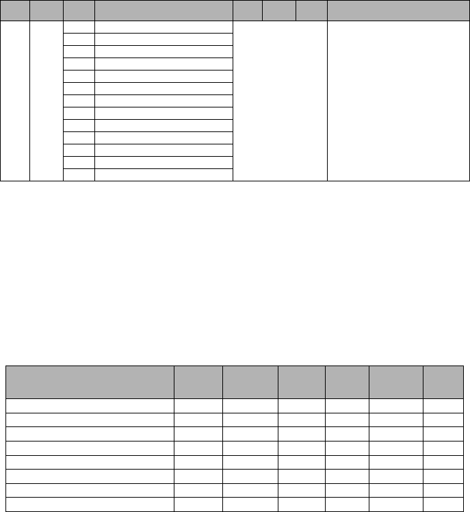
18
[021] Account Code
Default (FFFFFF)
The account code is included when transmitting any events generated by the Communicator. (e.g., Panel Absent
Trouble). It is recommended that the account code be the same as the control panel account number. Valid range:
00000
1
-FFFFF
E
. If 4 digit account codes are needed the 2 lowest digits shall be programmed as FF;(e.g., Account
1234 is programmed as:1234
FF
).
NOTE: Programming this Section with all 0 or F will cause a Module Configuration Trouble (yellow LED=12 flashes).
[022] Communications Format
Default (04)
Program 03 for Contact ID (CID). Program 04 for SIA. The module can be configured to send Communicator
Events in SIA or CID format. The SIA communication format follows the level 2 specifications of the SIA Digital
Communication Standard - October 1997. This format will send the account code along with its data transmission.
The transmission will look similar to the following at the receiver. Example:
Nri0 ET001
Where:
N
= New Event;
ri0
= Partition/Area identifier;
ET
= Panel Absent Trouble;
001
= Zone 001.
Communications Reporting Codes
[023] Panel Absent Trouble
Default (FF)
Program 00 to disable this event or FF to enable. This event will occur when communications with the panel have
been lost for more than 60 seconds.
[024] Panel Absent Trouble Restore
Default (FF)
Program 00 to disable this event or FF to enable. This event will occur when communications with the control panel
have resumed.
[025] Radio Activation Restore
Default (FF)
Program 00 to disable this event or FF to enable. This event will occur after any successful Connect24 program-
ming session.
System Test Options [026 - 029]
Test Transmissions to Primary Receiver, with Backup to Secondary Receiver:
Set Ethernet Section [026] to (FF); [027] to (00). Set GPRS Section [028] to (FF); [029] to (00).
• If the test transmission fails to the primary receiver it will backup to the secondary receiver.
• If the test transmission fails to the secondary receiver an FTC trouble will be generated.
Test Transmission Unique to Primary and Secondary Receivers:
Set Ethernet Section [026] to (FF); [027] to (FF). Set GPRS Section [028] to (FF); [029] to (FF).
• The module will send periodic test transmissions to each receiver independently, with no backups.
• If the test transmission fails to any of the programmed receivers, an FTC trouble will be generated.
45 +5
CAST Chinese Atlantic Standard Time
70 - FF Reserved
WKST West Kazakhstan Standard Time
PKT Pakistan Time
YEKT Yekaterinburg Time
UZT Uzbekistan Time
TMT Turkmenistan Time
TJT Tajikistan Time
TFT French Southern and Antarctic Time
MVT Maldives Time
MAWT Mawson Time
KGT Kyrgyzstan Time
HMT Heard and McDonald Island Time
DAVT Davis Time
Table 8: Communications Reporting Codes
Event SIA
Identifier
SIA
Reporting
Code
CID
Qualifier
CID
Event
Code
CID
Reporting
Code
CID
User/
Zone
[023] Panel Absent Trouble ET 001 1 3 55 001
[024] Panel Absent Trouble Restore ER 001 3 3 55 001
[025] Radio Activation Restore RS 001 3 5 52 001
[026] Ethernet 1 Test Transmission RP 001 1 6 A3 951
[027] Ethernet 2 Test Transmission RP 002 1 6 A3 952
[028] GPRS 1 Test Transmission RP 003 1 6 A3 955
[029] GPRS 2 Test Transmission RP 004 1 6 A3 956
[030] FTC Restore YK 001 3 3 54 001
Table 7: Time Zone Offset (Continued)
HEX Offset
Hours Std
Abbrev Location HEX Offset
Hours Std
Abbrev Location

19
Alternate Test Transmission:
Alternate Test Transmission can be enabled or disabled in Section [005] Toggle Option [7].
[026] Ethernet 1 Transmission
Default (FF)
Program 00 to disable this event transmission or FF to enable. See System Test Options (above) for details on settings.
[027] Ethernet 2 Transmission
Default (00)
Program 00 to disable this event transmission or FF to enable. See System Test Options (above) for details on settings.
[028] GPRS 1 Transmission
Default (FF)
Program 00 to disable this event transmission or FF to enable. See System Test Options (above) for details on settings.
[029] GPRS 2 Transmission
Default (00)
Program 00 to disable this event transmission or FF to enable. See System Test Options (above) for details on settings.
NOTE: The time interval (in minutes) between periodic tests is programmed in Section [125] (Ethernet)
and Section [225] (GPRS).
[030] FTC Restore
Default (FF)
Program 00 to disable this event transmission or FF to enable. This event will occur when an FTC Trouble on the
system restores.
[031] Panel Tamper Alarm
Default (FF)
This event will occur when a Panel Tamper is detected during the Entry Delay time. The Panel shall notify the
Communicator immediately, creating a Priority Tamper Alarm condition. Setting this option to 00 will disable
monitoring of this condition. See Table 9 for SIA and CID reporting codes. Program 00 to disable this event
transmission or FF to enable event transmission.
[032] Panel Tamper Alarm Restore
Default (FF)
Program 00 to disable this event transmission or FF to enable. This event will occur when a Panel Tamper event on
the system restores. See Table 9 for SIA and CID reporting codes.
Ethernet Receiver 1 Options
[101] Ethernet Receiver 1 Account Code
Default (0000000000)
The account code is used by the central station to distinguish between transmitters. This account code is used
when transmitting heartbeat signals to the central station receiver. Signals received from the Panel will use the con-
trol panel account number. Valid range: 000000000
1
-FFFFFFFFF
E
.
Programming this Section as all
0
or all
F
will cause a Module Configuration Trouble (yellow LED=12 flashes).
NOTE: If Ethernet Receiver 1 and GPRS Receiver 1 are programmed as the same receiver (IP and port
number are identical), Ethernet Receiver 1 account code will be used.
[102] Ethernet Receiver 1 DNIS
Default (000000)
The Dialled Number Information Service (DNIS) is used in addition to the Account Code to identify the Communica-
tor module at the central station. Valid range: 000000 - 099999. Value is entered as a leading 0 followed by the 5
digit DNIS. Format is Binary Coded Decimal (BCD.
NOTE: Each Ethernet/GPRS receiver must be programmed with a unique DNIS.
[103] Ethernet Receiver 1 Address
Default (127.000.000.001)
The default address enables the Communicator to operate in
Unattended Mode
.
Unattended Mode is used when a receiver is not available and the unit is required to perform DLS sessions. Typi-
cally used where the customer programs the control panel daily due to access control and still wants to receive
alarms without buying extra hardware (receiver) or software.
NOTE: When a valid IP address has been programmed, Ethernet Receiver 1 is enabled and will commu-
nicate events over the Ethernet channel.
Ethernet Receiver 1 and GPRS Receiver 1 may be configured to communicate to the same central station receiver.
To configure the device to operate using this Common Receiver Mode functionality, program Ethernet Receiver 1
and GPRS Receiver 1, IP address and port number with identical values.
NOTE: When operating in Common Receiver Mode, Ethernet Receiver 1 account code will be used for
Ethernet and GPRS.
[104] Ethernet Receiver 1 Remote Port
Default (0BF5/3061)
This Section determines the remote port of Ethernet receiver 1. Valid range: 0000 - FFFF.
Table 9: Panel Tamper Reporting Codes
Event SIA
Identifier
SIA
Reporting
Code
CID
Qualifier
CID
Event
Code
CID
Reporting
Code
CID
User/
Zone
[031] Panel Tamper ES 001 1 1 45 001
[032] Panel Tamper Restore EJ 001 3 1 45 001

20
[105] Ethernet Receiver 1 Local Port
Default (0BF4/3060)
Use this Section to set the value of the local outgoing port. Set the value of this port when your installation is
located behind a firewall and must be assigned a particular port number as determined by your central station
system administrator. Valid range: 0000 - FFFF.
[106] Ethernet Receiver 1 Domain Name
Default ()
Enter the Domain Name as 32 ASCII characters.
Programming this Section is not permitted on a UL/ULC listed system.
Ethernet Receiver 2 Options
[111] Ethernet Receiver 2 Account Code
Default (0000000000)
The account code is used by the central station to distinguish between transmitters. The account code is used
when transmitting heartbeat signals to the central station receiver. Signals received from the control panel will use
the control panel account number. Valid range: 000000000
1
- FFFFFFFFF
E
.
Programming this Section as all
0
or all
F
will cause a Module Configuration Trouble (yellow LED=12 flashes).
NOTE: If both Ethernet Receiver 2 and GPRS Receiver 2 are the same receiver (IP and port number are
identical), Ethernet Receiver 2 account will be used for Ethernet and GPRS.
[112] Ethernet Receiver 2 DNIS
Default (000000)
The DNIS is used in addition to the account code to identify the Communicator module at the central station. Valid
range: 000000 -
0
99999. Value is entered as leading
0
followed by the 5 digit DNIS. Format is BCD.
NOTE: Each Ethernet/GPRS receiver must be programmed with a unique DNIS.
[113] Ethernet Receiver 2 Address
Default (000.000.000.000)
Programming the Ethernet receiver 2 IP address with 000.000.000.000 will disable Ethernet.
Enter the Ethernet receiver 2 IP address. This address will be provided by your central station system administrator.
Format is 4 fields, each field is a 3 digit decimal. Valid range: 000-255.
NOTE: When a valid IP address has been programmed, Ethernet Receiver 2 is enabled and will commu-
nicate events over the Ethernet channel.
Ethernet Receiver 2 and GPRS Receiver 2 may be configured to communicate to the same central station receiver.
To configure the device to operate using this common receiver mode functionality, program the Ethernet Receiver 2
and GPRS Receiver 2, IP address and port number with the same values. When operating in common receiver
mode the Ethernet Receiver 2 account code will be used for communications over Ethernet and GPRS.
NOTE: Do not program Ethernet Receiver 1 and Ethernet Receiver 2 to communicate to the same
receiver.
[114] Ethernet Receiver 2 Remote Port
Default (0BF5/3061)
This Section is used to program the port number used by Ethernet Receiver 2. Set the value of this port when your
installation is located behind a firewall, and must be assigned a particular port number as determined by your cen-
tral station system administrator. Valid range: 0000 - FFFF.
NOTE: Do not program Ethernet Receiver 1 and Ethernet Receiver 2 Port with the same value.
[115] Ethernet Receiver 2 Local Port
Default (0BF9/3065)
Use this Section to program the value of the local outgoing port. You can set the value of this port when your instal-
lation is located behind a firewall and must be assigned a particular port number as determined by your network
administrator. Valid range: 0000 - FFFF.
NOTE: Do not program Ethernet Receiver 1 and Ethernet Receiver 2 Port with the same value.
[116] Ethernet Receiver 2 Domain Name
Default ( )
Programming this Section is not permitted on a UL/ULC listed system.
Enter the Domain Name as 32 Character ASCII.
Ethernet Options
[124] Ethernet Test Transmission Time
Default (9999)
Enter a 4 digit number (0000-2359) using the 24-hour clock format (HHMM) to set the test transmission time of day.
Valid range: 00 - 23 hours (HH) and 00 - 59 minutes (MM). Programming a value of (9999) will disable the test
transmission time.
NOTE: The internal date and time will automatically be programmed when the unit communicates with
the primary receiver.
[125] Ethernet Test Transmission Cycle
Default (000000)
This value represents the interval between test transmissions, in minutes. Valid range: 000000 - 999999 minutes.
Once the unit has sent the initial periodic test transmission, all future test transmissions will be offset by the pro-
grammed number of minutes. See Sections [026-029].
NOTE: Minimum value is 000005 minutes. Programming an interval that is less than 5 minutes will dis-
able test transmission.
Table 10: Ethernet Test Transmission Interval
Test Transmission Interval Daily Weekly Monthly
Programmed Minutes 001440 010080 043200
21
GPRS Receiver 1 Options
[201] GPRS Receiver 1 Account Code
Default (0000000000)
The account code is used by the central station to distinguish between transmitters. This account code is used
when transmitting heartbeat signals to the central station receiver. Signals received from the control panel will use
the control panel account number. Valid range: 000000000
1
- FFFFFFFFF
E
.
Programming this Section as all
0
or all
F
will cause a Module Configuration Trouble (yellow LED = 12 flashes).
[202] GPRS Receiver 1 DNIS
Default (000000)
The DNIS is used in addition to the account code to identify the Communicator module at the central station. Valid
range: 000000 -
0
99999. Values are entered as leading
0
followed by the five digit DNIS. Format is BCD.
NOTE: Each Ethernet/GPRS receiver must be programmed with a unique DNIS.
[203] GPRS Receiver 1 Address
Default (000.000.000.000)
Enter the GPRS Receiver 1 IP address. This information will be provided by your central station system administra-
tor. Each 3 digit segment of the address must be within a valid range of 000-255.
NOTE: When a valid IP address has been entered, the GPRS is enabled and will communicate events
over the GPRS channel.
[204] GPRS Receiver 1 Port
Default (0BF5/3061)
This Section determines the port used by GPRS Receiver 1. Change the default value of this port when your instal-
lation is located behind a firewall, and must be assigned a particular port number as determined by your central sta-
tion system administrator. Valid range: 0000 - FFFF.
NOTE: Programming this Section with 0000 will disable the receiver.
[205] GPRS Receiver 1 APN
Default ( )
The Access Point Name (APN) determines the GPRS network that the Communicator will connect to. This informa-
tion is available from your network carrier. Program this Section as 32 ASCII characters.
NOTE: When a SIM card with a custom APN is used, the unit will not have access to the internet. DLS
and remote flash can still be done if Section [221] is programmed with a valid Public APN.
[206] GPRS Receiver 1 Domain Name
Default ( )
Programming this Section is not permitted on a UL/ULC listed system.
Enter the Domain Name as 32 ASCII characters. This information will be provided by your central station system
administrator.
GPRS Receiver 2 Options
[211] GPRS Receiver 2 Account Code
Default (0000000000)
The account code is used by the central station to distinguish between different transmitters. This account code is
used when transmitting signals to the central station receiver. Signals received on the control panel will use the
control panel account number. Valid range: 000000000
1
- FFFFFFFFF
E
.
NOTE: Programming this Section as all 0 or F will cause a Module Configuration Trouble (yellow LED = 12 flashes).
[212] GPRS Receiver 2 DNIS
Default (000000)
The DNIS is used in addition to the Account Code to identify the Communicator module at the central station. Valid
range: 000000 -
0
99999. Values are entered as a 0 followed by the 5 digit DNIS value. Format is BCD.
NOTE: Each Ethernet/GPRS receiver must be programmed with a unique DNIS.
[213] GPRS Receiver 2 Address
Default (000.000.000.000)
Enter the GPRS Receiver 2 IP address. This IP address will be provided by your central station. Format is 4 fields,
each field is 3 digit decimal. Valid range: 000 - 255.
NOTE: When a valid address has been entered, GPRS Receiver 2 is enabled and will communicate
events over the GPRS path.
[214] GPRS Receiver 2 Port
Default (0BF5/3061)
This Section defines the port of GPRS Receiver 2. Change the value of this port when your installation is located
behind a firewall, and must be assigned a particular port number, as determined by your central station system
administrator. Valid range: 0000 - FFFF.
NOTE: Do not program GPRS Receiver 1 and GPRS Receiver 2 to communicate to the same receiver.
[215] GPRS Receiver 2 APN
Default ( )
The APN determines the GPRS network that the Communicator will connect to. This information is available from
your network carrier. Program this Section with up to 32 ASCII characters.
NOTE: When a SIM card with a custom APN is used, the unit will not have access to the internet. DLS
and remote flash can still be done if Section [221] is programmed with a valid Public APN.
[216] GPRS Receiver 2 Domain Name
Default ( )
Programming this Section is not permitted on a UL/ULC listed system.
Enter the GPRS Receiver 2 Domain Name with up to 32 ASCII characters.

22
GPRS Options
[221] GPRS Public Access Point Name
Default ( )
When the Communicator is operating on a private APN, use this Section to select a public APN for DLS and
Remote Firmware Update. This information is available from your network carrier. The APN identifies the public
GPRS network that the Communicator will connect to.
[222] GPRS Login User Name
Default ( )
Some network carriers require you to provide login credentials when connecting to an APN. Program your login
User name here. Format is up to 32 ASCII characters.
NOTE: This Section is not accessible via PC1616/PC1832/PC1864 keypad programming.
[223] GPRS Login Password
Default ( )
Some network carriers require you to provide login credentials when connecting to an APN. Program your login
password here.
Format is up to 32 ASCII characters.
[224] GPRS Test Transmission Time of Day
Default (9999)
Enter a 4 digit value using the 24-hour clock format (HHMM) to set the test transmission time of day. Valid range:
00-23 for the hours (HH) and 00-59 for the minutes (MM).
NOTE: To disable the test transmission time of day enter 9999 or FFFF in this Section.
The internal date and time will be automatically programmed by the primary receiver only.
[225] GPRS Test Transmission Cycle
Default (000000)
This value represents the interval in between test transmissions in minutes. Valid range: 000000 - 999999 minutes.
Once the unit has sent the initial periodic test transmission, all future test transmissions will be offset by the pro-
grammed number of minutes. See Sections [026 - 029].
NOTE: Minimum value is 000005 minutes. Programming an interval that is less than 5 minutes will dis-
able test transmission.
[226] GSM Trouble Delay
Default (00)
This option is used to program the delay, in minutes, for reporting a GSM Trouble Delay. Valid entries are 00 - FF.
(e.g., for a 10 minute GSM Trouble Delay enter:
0A
). There is no delay if value is programmed as 00.
Interactive Options
(TL260-SM/TL260GS-SM Only)
[651] Interactive Account Code
Default (MAC or IMEI)
This section is programmed as 2 field by 6 hexadecimal number. Valid range for each field is 000000 ~ FFFFFF.
The IMEI can be viewed in Section [997]. The MAC address can be viewed in Section [998].
[652] Interactive Access Code
Default (1234)
This section is programmed with the hexadecimal interactive access code. Valid range is 0000 ~ FFFF.
[653] Interactive IP Address
Default (000.000.000.000)
This section is programmed as with the IP address of the Interactive Server. Format is 4 fields, each field is a 3
digit decimal. Valid range: 000-255].
[654] Interactive Remote Port
Default (0BFC/3068)
This Section is used to program the port number used by Interactive. Set the value of this port when your installa-
tion is located behind a firewall, and must be assigned a particular port number as determined by your central sta-
tion system administrator. Valid range: 0000 - FFFF.
[655] Interactive Local Port
Default (0BFD/3069)
Use this Section to set the value of the Interactive local outgoing port. Set the value of this port when your installa-
tion is located behind a firewall and must be assigned a particular port number as determined by your central sta-
tion system administrator. Valid range: 0000 - FFFF.
[656] Interactive Domain Name
Default ( )
Enter the Interactive Domain Name as 32 ASCII characters.
Programming this Section is not permitted on a UL/ULC listed system.
[657] Interactive Incoming Port
Default (0BFE/3070)
The Interactive Incoming Local Port (listening port) is the port Interactive will use when connecting to the Communi-
cator. If a router or gateway is used, it must be programmed with a Transmission Control Protocol (TCP) port for-
ward for this port to the Communicator module IP address. Valid range: 0000-FFFF.
Table 11: Ethernet Test Transmission Interval
Test Transmission Interval Daily Weekly Monthly
Programmed Minutes 001440 010080 043200

23
[658] Interactive Access Point Name 1
Default ( )
This section is programmed as 32 character ASCII. Receiver 1 shall use this APN to connect to the Interactive
network. Two sockets are opened, one for each receiver. If both APNs are left blank, the unit will eventually dis-
play a Receiver not Available Trouble.
[659] Interactive Access Point Name 2
Default ( )
This section is programmed as 32 character ASCII. Receiver 2 shall use this APN for Interactive.
[661] Interactive Baud Rate
Default (05)
This section is programmed with the baud rate used. Valid entries are provided in the table below. Default baud
rate is 115.2 KB.
[662] Interactive Port Settings Toggle
Program this section Toggles to select the Parity used for Interactive data transfers:
[1] Parity Enable
Default (OFF)
ON: Parity is enabled.
OFF: Parity is disabled.
[2] Parity Type
Default (OFF)
ON: Even Parity is enabled.
OFF: Odd Parity is enabled.
[3] Stop Bits
Default (OFF)
ON: One Stop bit is used.
OFF: Two Stop bits are used.
[4] Flow Control
Default (OFF)
ON: Flow Control is enabled.
OFF: Flow Control is disabled.
[5]-[8]Reserved
Default (OFF)
[671] Lifestyle Event Toggle
This section determines the events recorded in the Lifestyle Log. When the lifestyle buffer is 75% full, the com-
municator will connect to the iControl Server and upload the lifestyle information.
The log can buffer 1,000 lifestyle events.
NOTE: No FTC shall be generated for Lifestyle Events.
[1] Lifestyle Log Alarm/Restore
Default (ON)
[2] Lifestyle Log Tamper/Restore
Default (ON)
[3] Lifestyle Log Opening/Closing
Default (ON)
[4] Lifestyle Log System Maintenance
Default (ON)
[5] Lifestyle Log System Test
Default (ON)
[6] Lifestyle Log Communicator Events
Default (ON)
[7]-[8] Reserved
Default (ON)
[672] Lifestyle Zone 1 - 8 Toggle Options
The default for each Lifestyle Zone Toggle is ON.
Table 12: Interactive Baud Rate Settings
HEX Value 01 02 03 04 05
Baud Rate 9600 19200 38400 57600 115200
Table 13: Lifestyle Zone 1 - 8 Toggle
TOGGLE 01 02 03 04 05 06 07 08
ZONE 12345678

24
[673] Lifestyle Zone 9 - 16 Toggle Options
The default for each Lifestyle Zone Toggle is ON.
[674] Lifestyle Zone 17 - 24 Toggle Options
The default for each Lifestyle Zone Toggle is ON.
[675] Lifestyle Zone 25 - 32 Toggle Options
The default for each Lifestyle Zone Toggle is ON.
[676] Lifestyle Zone 33 - 40 Toggle Options
The default for each Lifestyle Zone Toggle is ON.
[677] Lifestyle Zone 41 - 48 Toggle Options
The default for each Lifestyle Zone Toggle is ON.
[678] Lifestyle Zone 49 - 56 Toggle Options
The default for each Lifestyle Zone Toggle is ON.
[679] Lifestyle Zone 57 - 64 Toggle Options
The default for each Lifestyle Zone Toggle is ON.
[681] Notification Event Toggle
This section determines the Notification events that are reported. Default for all is OFF.
[1] Lifestyle Log Alarm/Restore
Default (OFF)
[2] Lifestyle Log Tamper/Restore
Default (OFF)
[3] Lifestyle Log Opening/Closing
Default (OFF)
[4] Lifestyle Log System Maintenance
Default (OFF)
[5] Lifestyle Log System Test
Default (OFF)
[6] Lifestyle Log Communicator Events
Default (OFF)
[7]-[8] Reserved
Default (OFF)
[682] Notification Zone 1 - 8 Toggle Options
The default for each Notification Zone Toggle is OFF.
Table 14: Lifestyle Zone 9 - 16 Toggle
TOGGLE 01 02 03 04 05 06 07 08
ZONE 9 10111213141516
Table 15: Lifestyle Zone 17 - 24 Toggle
TOGGLE 01 02 03 04 05 06 07 08
ZONE 17 18 19 20 21 22 23 24
Table 16: Lifestyle Zone 25 - 32 Toggle
TOGGLE 01 02 03 04 05 06 07 08
ZONE 25 26 27 28 29 30 31 32
Table 17: Lifestyle Zone 33 - 40 Toggle
TOGGLE 01 02 03 04 05 06 07 08
ZONE 33 34 35 36 37 38 39 40
Table 18: Lifestyle Zone 41 - 48 Toggle
TOGGLE 01 02 03 04 05 06 07 08
ZONE 41 42 43 44 45 46 47 48
Table 19: Lifestyle Zone 49 - 56 Toggle
TOGGLE 01 02 03 04 05 06 07 08
ZONE 49 50 51 52 53 54 55 56
Table 20: Lifestyle Zone 57 - 64 Toggle
TOGGLE 01 02 03 04 05 06 07 08
ZONE 57 58 59 60 61 62 63 64
Table 21: Notification Zone 1 - 8 Toggle
TOGGLE 01 02 03 04 05 06 07 08
ZONE 12345678

25
[683] Notification Zone 9 - 16 Toggle Options
The default for each Notification Zone Toggle is OFF.
[684] Notification Zone 17 - 24 Toggle Options
The default for each Notification Zone Toggle is OFF.
[685] Notification Zone 25 - 32 Toggle Options
The default for each Notification Zone Toggle is OFF.
[686] Notification Zone 33 - 40 Toggle Options
The default for each Notification Zone Toggle is OFF.
[687] Notification Zone 41 - 48 Toggle Options
The default for each Notification Zone Toggle is OFF.
[688] Notification Zone 49 - 56 Toggle Options
The default for each Notification Zone Toggle is OFF.
[689] Notification Zone 57 - 64 Toggle Options
The default for each Notification Zone Toggle is OFF.
Receiver Diagnostic Testing
[901] Diagnostic Test Transmission
[1] Ethernet 1 (OFF).
[2] Ethernet 2 (OFF).
[3] GPRS 1 (OFF).
[4] GPRS 2 (OFF).
[5],[6],[7],[8] Reserved (OFF).
This Section may be used by the installer to force the Communicator to send an immediate test transmission to
specific receivers, to verify that the communications paths are available. Diagnostic Test Transmission failure
will indicate as FTC trouble (Yellow LED = 9 flashes). If an FTC error occurs when testing all receivers, select
only one receiver and repeat test to isolate the receiver that is not communicating.
System Information (Read Only)
NOTE: Sections [988] - [998] are provided for information (Read Only). Values can not be modified in
these Sections.
[987] Language Version
This Section will display the current Language version of the Communicator.
[988] DNS 1 IP Address
This Section will display the IP address of DNS Server 1. This is useful when the unit is configured for DHCP and
you need to see the IP address was assigned to the device by the DHCP Server. This value is programmed in Sec-
tion [007] or assigned by DHCP.
[989] DNS 2 IP Address
This Section will display the IP address of DNS Server 2. This is useful when the unit is configured for DHCP and
you need to see the IP address that was assigned to the device by the DHCP Server. This value is programmed in
Section [008] or assigned by DHCP.
[990] Boot Loader Version
This Section will display the current Boot Loader version of the Communicator.
Table 22: Notification Zone 9 - 16 Toggle
TOGGLE 01 02 03 04 05 06 07 08
ZONE 9 10111213141516
Table 23: Notification Zone 17 - 24 Toggle
TOGGLE 01 02 03 04 05 06 07 08
ZONE 17 18 19 20 21 22 23 24
Table 24: Notification Zone 25 - 32 Toggle
TOGGLE 01 02 03 04 05 06 07 08
ZONE 25 26 27 28 29 30 31 32
Table 25: Notification Zone 33 - 40 Toggle
TOGGLE 01 02 03 04 05 06 07 08
ZONE 33 34 35 36 37 38 39 40
Table 26: Notification Zone 41 - 48 Toggle
TOGGLE 01 02 03 04 05 06 07 08
ZONE 41 42 43 44 45 46 47 48
Table 27: Notification Zone 49 - 56 Toggle
TOGGLE 01 02 03 04 05 06 07 08
ZONE 49 50 51 52 53 54 55 56
Table 28: Notification Zone 57 - 64 Toggle
TOGGLE 01 02 03 04 05 06 07 08
ZONE 57 58 59 60 61 62 63 64
26
[991] Firmware Version
This Section will display the current firmware version of the device. Update worksheets with new version after a
flash update is completed.
[992] Ethernet IP Address
This Section will display the IP address of the Ethernet connection. This value is programmed in Section [001] or
assigned by DHCP.
[993] Ethernet Gateway Address
This Section will display the IP address of the Ethernet Gateway. This value is programmed in Section [003] or
assigned by DHCP.
[994] GPRS IP Address
This Section will display the current dynamic IP address assigned by DHCP to the GPRS connection.
NOTE: GPRS uses DHCP (Dynamic IP) only. The GPRS IP address is always provided by the GSM
network (i.e., not programmable).
[995] SIM Number
This Section will display the Subscriber Identity Module (SIM) number of the SIM card installed in the Communica-
tor. Format is: Major Industry Identifier (2 digits) Mobile Country Code (2 or 3 digits); Mobile Network Code (2 - 3
digits); Unique Number (10 - 12 digits); and Checksum (1 digit). Valid SIM numbers range is: 18 - 21 numbers. This
number is printed on SIM and the outside of the Communicator carton.
NOTE: The Checksum digit is omitted on 19 digit SIM Card numbers.
[996] GSM Telephone Number
NOTE: This Section will display the GSM telephone number of the SIM. This telephone number is
required by the Installer for DLS and remote firmware (flash) update. User can access this telephone
number by entering [*] [6] < > “GSM Phone No.” to display the phone number.
[997] IMEI Number
This Section will display the unique 15 digit International Mobile Equipment Identity (IMEI) of the radio. Format is:
Reporting Body Identifier (2 digits), Allocation Number (4 digits); Final Assembly Code (2 digits); Serial Number (6
digits); and a check digit.
[998] MAC Address
This Section will display the unique12 digit, hexadecimal number assigned as the Media Access Control (MAC)
address of the device.
System Reset Defaults
[999] Software Default
Default (99);
The Software default allows the installer to refresh the unit after changes and also return the Communicator to the
default state.
00
:
Default Module
. All programming Sections in module revert to factory settings. This will erase all existing
programming of the unit.
55
:
Reset
. The Communicator is reset. This option is equivalent to power cycling the Communicator.

27
System Options
[001] Ethernet IP Address
Default (000.000.000.000)
|____|____|____||____|____|____||____|____|____|____|____|____|
[002] Ethernet IP Subnet Mask
Default (255.255.255.000)
|____|____|____||____|____|____||____|____|____|____|____|____|
[003] Ethernet Gateway IP Address
Default (000.000.000.000)
|____|____|____||____|____|____||____|____|____|____|____|____|
[004] Receiver Supervision Interval
Default (0087/135) Valid range: 0000 - FFFF.
|____|____|____|____|
[005] System Toggle Options
|____| [1] Ethernet Receiver 1 Supervised Default (OFF).
|____| [2] GPRS Receiver 1 Supervised Default (OFF).
|____| [3] Supervision Type Default (OFF).
|____| [4] Primary Communications Path.
Default [OFF] TL260GS-SM; [ON]GS2060-SM.
|____| [5] Redundant Communications Default (OFF).
|____| [6] Remote Firmware Upgrade Default (ON).
|____| [7] Alternate Test Transmission Default (OFF).
|____| [8] GSM Low Signal Trouble Default (OFF).
[006] System Toggle Options 2
|____| [1] Ethernet Receiver 1 Enabled Default (ON).
|____| [2] Ethernet Receiver 2 Enabled Default (ON).
|____| [4] GPRS Receiver 1 Enabled Default (ON).
|____| [5] GPRS Receiver 2 Enabled Default (ON).
|____| [7] DLS Over GPRS Default (ON).
|____| [8] Interactive Over GPRS Default (ON).
[007] DNS Server IP 1
Programming not permitted on UL/ULC listed system.
Default (000.000.000.000)
|____|____|____||____|____|____||____|____|____|____|____|____|
[008] DNS Server IP 2
Programming not permitted on UL/ULC listed system.
Default (000.000.000.000)
|____|____|____||____|____|____||____|____|____|____|____|____|
Programming Options
[011] Installer Code
Default (CAFE) Valid range: 0000 - FFFF.
|____|____|____|____|
[012] DLS Incoming Port
Default (0BF6/3062) Valid range: 0000 - FFFF.
|____|____|____|____|
[013] DLS Outgoing Port
Default (0BFA/3066) Valid range: 0000 - FFFF.
|____|____|____|____|
[020] Time Zone
Default (00) Valid range: 00 - FF.
|____|____|
[021] Account Code
Default (FFFFFF)
|____|____|____|____|____|____|
[022] Communications Format
Default (04) Program 03 (CID), 04 (SIA).
|____|____|
[023] Panel Absent Trouble
Default (FF) ; Program 00 disable or FF enable.
|____|____|
[024] Panel Absent Trouble Restore
Default (FF) Program 00 disable or FF enable.
|____|____|
[025] Radio Activation Restore
Default (FF) Program 00 disable or FF enable.
|____|____|
System Test Options [026 - 029]
[026] Ethernet 1 Transmission
Default (FF) Program 00 disable or FF enable.
|____|____|
[027] Ethernet 2 Transmission
Default (00) Program 00 disable or FF enable.
|____|____|
[028] GPRS 1 Transmission
Default (FF) Program 00 disable or FF enable.
|____|____|
[029] GPRS 2 Transmission
Default (00) Program 00 disable or FF enable.
|____|____|
[030] FTC Restore
Default (FF) Program 00 disable or FF enable.
|____|____|
[031] Panel Tamper Alarm
Default (FF) Program 00 disable or FF enable.
|____|____|
[032] Panel Tamper Alarm Restore
Default (FF) Program 00 disable or FF enable.
|____|____|
Ethernet Receiver 1 Options
[101] Ethernet Receiver 1 Account Code
Default (0000000000)
Valid range: 0000000001 - FFFFFFFFFE.
|____|____|____|____|____|____|____|____|____|____|
[102] Ethernet Receiver 1 DNIS
Default (000000) Valid range: 000000 - FFFFFF.
|____|____|____|____|____|____|
[103] Ethernet Receiver 1 Address
Default (127.000.000.001)
|____|____|____||____|____|____||____|____|____|____|____|____|
[104] Ethernet Receiver 1 Remote Port
Default (0BF5/3061) Valid range: 0000 - FFFF.
|____|____|____|____|
COMMUNICATOR PROGRAMMING WORKSHEETS
28
[105] Ethernet Receiver 1 Local Port
Default (0BF4/3060) Valid range: 0000 - FFFF.
|____|____|____|____|
[106] Ethernet Receiver 1 Domain Name
Default () 32 ASCII characters.
Programming not permitted on UL/ULC listed system.
________________________________
Ethernet Receiver 2 Options
[111] Ethernet Receiver 2 Account Code
Default (0000000000)
Valid range: 0000000001 - FFFFFFFFFE.
|____|____|____|____|____|____|____|____|____|____|
[112] Ethernet Receiver 2 DNIS
Default (000000) Valid range: 000000 - 0FFFFF.
|____|____|____|____|____|____|
[113] Ethernet Receiver 2 Address
Default (000.000.000.000)
|____|____|____||____|____|____||____|____|____|____|____|____|
[114] Ethernet Receiver 2 Remote Port
Default (0BF5/3061) Valid range: 0000 - FFFF.
|____|____|____|____|
[115] Ethernet Receiver 2 Local Port
Default (0BF9/3065) Valid range: 0000 -FFFF.
|____|____|____|____|
[116] Ethernet Receiver 2 Domain Name Default ( )
Programming not permitted on UL/ULC listed system.
____________________________________
Ethernet Options
[124] Ethernet Test Transmission Time
Default (9999) Valid: 00-23(HH); 00-59(MM)
|____|____|____|____|
[125] Ethernet Test Transmission Cycle
Default (000000)
Valid range: 000000 - 999999 minutes.
|____|____|____|____|____|____|
GPRS Receiver 1 Options
[201] GPRS Receiver 1 Account Code
Default (0000000000)
Valid range: 0000000001 - FFFFFFFFFE.
|____|____|____|____|____|____|____|____|____|____|
[202] GPRS Receiver 1 DNIS
Default (000000) Valid range: 000000 - 0FFFFF.
|____|____|____|____|____|____|
[203] GPRS Receiver 1 Address
Default (000.000.000.000) . Valid range: 000-255.
|____|____|____||____|____|____||____|____|____|____|____|____|
[204] GPRS Receiver 1 Port
Default (0BF5/3061) Valid range: 0000 - FFFF.
|____|____|____|____|
[205] GPRS Receiver 1 APN Default ( )
32 ASCII characters.
____________________________________
[206] GPRS Receiver 1 Domain Name Default ( )
Programming not permitted on UL/ULC listed system.
32 Character ASCII characters.
____________________________________
GPRS Receiver 2 Options
[211] GPRS Receiver 2 Account Code
Default (0000000000)
Valid range: 0000000001 - FFFFFFFFFE.
|____|____|____|____|____|____|____|____|____|____|
[212] GPRS Receiver 2 DNIS
Default (000000)
Valid range: 000000 - 0FFFFF.
|____|____|____|____|____|____|
[213] GPRS Receiver 2 Address
Default (000.000.000.000)
Valid segment range: 000-255
|____|____|____||____|____|____||____|____|____|____|____|____|
[214] GPRS Receiver 2 Port
Default (0BF5/3061) Valid range: 0000 - FFFF.
|____|____|____|____|
[215] GPRS Receiver 2 APN
Default ( ) 32 ASCII characters.
____________________________________
[216] GPRS Receiver 2 Domain Name
Default ( )
Programming not permitted on UL/ULC listed system.
32 ASCII characters.
____________________________________
GPRS Options
[221] GPRS Public Access Point Name
Default ( ) 32 ASCII characters
____________________________________
[222] GPRS Login User Name
Default ( ) 32 ASCII characters.
____________________________________
[223] GPRS Login Password
Default ( ) 32 ASCII characters.
____________________________________
[224] GPRS Test Transmission Time of Day
Default (9999)
Valid range: 00 - 23 hrs. (HH) 00 - 59 min. (MM).
|____|____|____|____|
[225] GPRS Test Transmission Cycle
Default (000000)
Valid range: 000000 - 999999 minutes.
|____|____|____|____|____|____|
[226] GSM Trouble Delay
Default (00)
Program 00 disable or FF enable.
|____|____|
Interactive Options
[651] Interactive Account Code
Default (MAC or IMEI)
|____|____|____|____|____|____| |____|____|____|____|____|____|
29
[652] Interactive Access Code
Default (1234)
|____|____|____|____|
[653] Interactive IP Address
Default (000.000.000.000)
[654] Interactive Remote Port
Default (0BFC/3068)
|____|____|____|____|
[655] Interactive Local Port
Default (0BFD/3069)
|____|____|____|____|
[656] Interactive Domain Name
Default ( )
Programming not permitted on UL/ULC listed system.
____________________________________
[657] Interactive Incoming Port
Default (0BFE/3070)
|____|____|____|____|
[658] Interactive Access Point Name 1
Default ( )
____________________________________
[659] Interactive Access Point Name 2
Default ( )
____________________________________
[661] Interactive Baud Rate
Default (05)
|____|____|
[662] Interactive Port Settings Toggle
|____| [1] Parity Enabled Default (OFF).
|____| [2] Even/Odd Parity Default (OFF).
|____| [3]1 or 2 Stop Bits Default (OFF).
|____| [4] Flow Control. Default (OFF).
[671] Lifestyle Event Toggle
|____| [1] Alarm/Restore Default (ON).
|____| [2] Tamper/Restore Default (ON).
|____| [3] Opening/Closing Default (ON).
|____| [4] System Maintenance Default (ON).
|____| [5] System Test Default (ON).
|____| [6] Internal Events Default (ON).
[672] Lifestyle Zone 1 - 8 Toggle Options
|____|____|____|____|____|____|____|____|
1 2 3 4 5 6 7 8
[673] Lifestyle Zone 9 - 16 Toggle Options
|____|____|____|____|____|____|____|____|
9 10 11 12 13 14 15 16
[674] Lifestyle Zone 17 - 24 Toggle Options
|____|____|____|____|____|____|____|____|
17 18 19 20 21 22 23 24
[675] Lifestyle Zone 25 - 32 Toggle Options
|____|____|____|____|____|____|____|____|
25 26 27 28 29 30 31 32
[676] Lifestyle Zone 33 - 40 Toggle Options
|____|____|____|____|____|____|____|____|
33 34 35 36 37 38 39 40
[677] Lifestyle Zone 41 - 48 Toggle Options
|____|____|____|____|____|____|____|____|
41 42 43 44 45 46 47 48
[678] Lifestyle Zone 49 - 56 Toggle Options
|____|____|____|____|____|____|____|____|
49 50 51 52 53 54 55 56
[679] Lifestyle Zone 57 - 64 Toggle Options
|____|____|____|____|____|____|____|____|
57 58 59 60 61 62 63 64
[681] Notification Event Toggle
|____| [1] Alarm/Restore Default (OFF).
|____| [2] Tamper/Restore Default (OFF).
|____| [3] Opening/Closing Default (OFF).
|____| [4] System Maintenance. Default (OFF).
|____| [5] System Test Default (OFF).
|____| [6] Internal Events Default (OFF).
[682] Notification Zone 1 - 8 Toggle Options
|____|____|____|____|____|____|____|____|
1 2 3 4 5 6 7 8
[683] Notification Zone 9 - 16 Toggle Options
|____|____|____|____|____|____|____|____|
9 10 11 12 13 14 15 16
[684] Notification Zone 17 - 24 Toggle Options
|____|____|____|____|____|____|____|____|
17 18 19 20 21 22 23 24
[685] Notification Zone 25 - 32 Toggle Options
|____|____|____|____|____|____|____|____|
25 26 27 28 29 30 31 32
[686] Notification Zone 33 - 40 Toggle Options
|____|____|____|____|____|____|____|____|
33 34 35 36 37 38 39 40
[687] Notification Zone 41 - 48 Toggle Options
|____|____|____|____|____|____|____|____|
41 42 43 44 45 46 47 48
[688] Notification Zone 49 - 56 Toggle Options
|____|____|____|____|____|____|____|____|
49 50 51 52 53 54 55 56
[689] Notification Zone 57 - 64 Toggle Options
|____|____|____|____|____|____|____|____|
57 58 59 60 61 62 63 64
30
Receiver Diagnostic Testing
[901] Diagnostic Test Transmission
|___| [1] Ethernet 1 Default (OFF).
|___| [2] Ethernet 2 Default (OFF).
|___| [3] GPRS 1 Default (OFF).
|___| [4] GPRS 2 Default (OFF).
System Information (Read Only)
[988] DNS 1 IP Address
|____|____|____||____|____|____||____|____|____|____|____|____|
[989] DNS 2 IP Address
|____|____|____||____|____|____||____|____|____|____|____|____|
[991] Firmware Version
|____|____|____|____|____|____|____|____|
[992] Ethernet IP Address
|____|____|____||____|____|____||____|____|____|____|____|____|
[993] Ethernet Gateway Address
|____|____|____||____|____|____||____|____|____|____|____|____|
[994] GPRS IP Address
|____|____|____||____|____|____||____|____|____|____|____|____|
[995] SIM Number
____________________________________
[996] GSM Telephone Number
This number is required for DLS, and Firmware
upgrades.
____________________________________
[997] IMEI Number
____________________________________
[998] MAC Address
|____|____|____|____|____|____| |____|____|____|____|____|____|
System Reset Defaults
[999] Software Default
Default (99); Valid entries are 00 or 55
|____|____|
31
E
ND
U
SER
L
ICENCE
A
GREEMENT
IMPORTANT - READ CAREFULLY: DSC Software purchased
with or without Products and Components
is copyrighted and is purchased under the following license
terms:
This End-User License Agreement (“EULA”) is a legal agree-
ment between You (the company, individual or entity who
acquired the Software and any related Hardware) and Digital
Security Controls, a division of Tyco Safety Products Can-
ada Ltd. (“DSC”), the manufacturer of the integrated security
systems and the developer of the software and any related
products or components (“HARDWARE”) which You acquired.
If the DSC software product (“SOFTWARE PRODUCT” or
“SOFTWARE”) is intended to be accompanied by HARD-
WARE, and is NOT accompanied by new HARDWARE, You
may not use, copy or install the SOFTWARE PRODUCT. The
SOFTWARE PRODUCT includes computer software, and
may include associated media, printed materials, and “online”
or electronic documentation.
Any software provided along with the SOFTWARE PRODUCT
that is associated with a separate end-user license agreement
is licensed to You under the terms of that license agreement.
By installing, copying, downloading, storing, accessing or oth-
erwise using the SOFTWARE PRODUCT, You agree uncondi-
tionally to be bound by the terms of this EULA, even if this
EULA is deemed to be a modification of any previous arrange-
ment or contract. If You do not agree to the terms of this
EULA, DSC is unwilling to license the SOFTWARE PRODUCT
to You, and You have no right to use it.
SOFTWARE PRODUCT LICENSE
The SOFTWARE PRODUCT is protected by copyright laws
and international copyright treaties, as well as other intellec-
tual property laws and treaties. The SOFTWARE PRODUCT
is licensed, not sold.
1.GRANT OF LICENSE This EULA grants You the following
rights:
(a)Software Installation and Use - For each license You
acquire, You may have only one copy of the SOFTWARE
PRODUCT installed.
(b)Storage/Network Use - The SOFTWARE PRODUCT may
not be installed, accessed, displayed, run, shared or used con-
currently on or from different computers, including a worksta-
tion, terminal or other digital electronic device (“Device”). In
other words, if You have several workstations, You will have to
acquire a license for each workstation where the SOFTWARE
will be used.
(c)Backup Copy - You may make back-up copies of the
SOFTWARE PRODUCT, but You may only have one copy per
license installed at any given time. You may use the back-up
copy solely for archival purposes. Except as expressly pro-
vided in this EULA, You may not otherwise make copies of the
SOFTWARE PRODUCT, including the printed materials
accompanying the SOFTWARE.
2. DESCRIPTION OF OTHER RIGHTS AND LIMITATIONS
(a)Limitations on Reverse Engineering, Decompilation
and Disassembly - You may not reverse engineer, decompile,
or disassemble the SOFTWARE PRODUCT, except and only
to the extent that such activity is expressly permitted by appli-
cable law notwithstanding this limitation. You may not make
any changes or modifications to the Software, without the writ-
ten permission of an officer of DSC. You may not remove any
proprietary notices, marks or labels from the Software Product.
You shall institute reasonable measures to ensure compliance
with the terms and conditions of this EULA.
(b)Separation of Components - The SOFTWARE PROD-
UCT is licensed as a single product. Its component parts may
not be separated for use on more than one HARDWARE unit.
(c)Single INTEGRATED PRODUCT - If You acquired this
SOFTWARE with HARDWARE, then the SOFTWARE PROD-
UCT is licensed with the HARDWARE as a single integrated
product. In this case, the SOFTWARE PRODUCT may only be
used with the HARDWARE as set forth in this EULA.
(d)Rental - You may not rent, lease or lend the SOFTWARE
PRODUCT. You may not make it available to others or post it
on a server or web site.
(e)Software Product Transfer - You may transfer all of Your
rights under this EULA only as part of a permanent sale or
transfer of the HARDWARE, provided You retain no copies,
You transfer all of the SOFTWARE PRODUCT (including all
component parts, the media and printed materials, any
upgrades and this EULA), and provided the recipient agrees to
the terms of this EULA. If the SOFTWARE PRODUCT is an
upgrade, any transfer must also include all prior versions of
the SOFTWARE PRODUCT.
(f)Termination - Without prejudice to any other rights, DSC
may terminate this EULA if You fail to comply with the terms
and conditions of this EULA. In such event, You must destroy
all copies of the SOFTWARE PRODUCT and all of its compo-
nent parts.
(g)Trademarks - This EULA does not grant You any rights in
connection with any trademarks or service marks of DSC or its
suppliers.
3. COPYRIGHT - All title and intellectual property rights in and
to the SOFTWARE PRODUCT (including but not limited to any
images, photographs, and text incorporated into the SOFT-
WARE PRODUCT), the accompanying printed materials, and
any copies of the SOFTWARE PRODUCT, are owned by DSC
or its suppliers. You may not copy the printed materials
accompanying the SOFTWARE PRODUCT. All title and intel-
lectual property rights in and to the content which may be
accessed through use of the SOFTWARE PRODUCT are the
property of the respective content owner and may be pro-
tected by applicable copyright or other intellectual property
laws and treaties. This EULA grants You no rights to use such
content. All rights not expressly granted under this EULA are
reserved by DSC and its suppliers.
4. EXPORT RESTRICTIONS - You agree that You will not
export or re-export the SOFTWARE PRODUCT to any coun-
try, person, or entity subject to Canadian export restrictions.
5. CHOICE OF LAW - This Software License Agreement is
governed by the laws of the Province of Ontario, Canada.
6. ARBITRATION - All disputes arising in connection with this
Agreement shall be determined by final and binding arbitration
in accordance with the Arbitration Act, and the parties agree to
be bound by the arbitrator’s decision. The place of arbitration
shall be Toronto, Canada, and the language of the arbitration
shall be English.
7. LIMITED WARRANTY
(a) NO WARRANTY - DSC PROVIDES THE SOFTWARE “AS
IS” WITHOUT WARRANTY. DSC DOES NOT WARRANT THAT
THE SOFTWARE WILL MEET YOUR REQUIREMENTS OR
THAT OPERATION OF THE SOFTWARE WILL BE UNINTER-
RUPTED OR ERROR-FREE.
(b) CHANGES IN OPERATING ENVIRONMENT - DSC shall
not be responsible for problems caused by changes in the
operating characteristics of the HARDWARE, or for problems
in the interaction of the SOFTWARE PRODUCT with non-
DSC-SOFTWARE or HARDWARE PRODUCTS.
(c) LIMITATION OF LIABILITY; WARRANTY REFLECTS
ALLOCATION OF RISK - IN ANY EVENT, IF ANY STATUTE
IMPLIES WARRANTIES OR CONDITIONS NOT STATED IN
THIS LICENSE AGREEMENT, DSC’S ENTIRE LIABILITY
UNDER ANY PROVISION OF THIS LICENSE AGREEMENT
SHALL BE LIMITED TO THE GREATER OF THE AMOUNT
ACTUALLY PAID BY YOU TO LICENSE THE SOFTWARE
PRODUCT AND FIVE CANADIAN DOLLARS (CAD$5.00).
BECAUSE SOME JURISDICTIONS DO NOT ALLOW THE
EXCLUSION OR LIMITATION OF LIABILITY FOR CONSE-
QUENTIAL OR INCIDENTAL DAMAGES, THE ABOVE LIMI-
TATION MAY NOT APPLY TO YOU.
(d) DISCLAIMER OF WARRANTIES - THIS WARRANTY
CONTAINS THE ENTIRE WARRANTY AND SHALL BE IN
LIEU OF ANY AND ALL OTHER WARRANTIES, WHETHER
EXPRESSED OR IMPLIED (INCLUDING ALL IMPLIED WAR-
RANTIES OF MERCHANTABILITY OR FITNESS FOR A
PARTICULAR PURPOSE) AND OF ALL OTHER OBLIGA-
TIONS OR LIABILITIES ON THE PART OF DSC. DSC
MAKES NO OTHER WARRANTIES. DSC NEITHER
ASSUMES NOR AUTHORIZES ANY OTHER PERSON PUR-
PORTING TO ACT ON ITS BEHALF TO MODIFY OR TO
CHANGE THIS WARRANTY, NOR TO ASSUME FOR IT ANY
OTHER WARRANTY OR LIABILITY CONCERNING THIS
SOFTWARE PRODUCT.
(e) EXCLUSIVE REMEDY AND LIMITATION OF WAR-
RANTY - UNDER NO CIRCUMSTANCES SHALL DSC BE
LIABLE FOR ANY SPECIAL, INCIDENTAL, CONSEQUEN-
TIAL OR INDIRECT DAMAGES BASED UPON BREACH OF
WARRANTY, BREACH OF CONTRACT, NEGLIGENCE,
STRICT LIABILITY, OR ANY OTHER LEGAL THEORY. SUCH
DAMAGES INCLUDE, BUT ARE NOT LIMITED TO, LOSS OF
PROFITS, LOSS OF THE SOFTWARE PRODUCT OR ANY
ASSOCIATED EQUIPMENT, COST OF CAPITAL, COST OF
SUBSTITUTE OR REPLACEMENT EQUIPMENT, FACILI-
TIES OR SERVICES, DOWN TIME, PURCHASERS TIME,
THE CLAIMS OF THIRD PARTIES, INCLUDING CUSTOM-
ERS, AND INJURY TO PROPERTY.
WARNING: DSC recommends that the entire system be com-
pletely tested on a regular basis. However, despite frequent
testing, and due to, but not limited to, criminal tampering or
electrical disruption, it is possible for this SOFTWARE PROD-
UCT to fail to perform as expected.
32
Limited Warranty
Digital Security Controls warrants the original pur-
chaser that for a period of twelve months from the
date of purchase, the product shall be free of defects
in materials and workmanship under normal use. Dur-
ing the warranty period, Digital Security Controls
shall, at its option, repair or replace any defective
product upon return of the product to its factory, at no
charge for labour and materials. Any replacement
and/or repaired parts are warranted for the remainder
of the original warranty or ninety (90) days, whichever
is longer. The original purchaser must promptly notify
Digital Security Controls in writing that there is defect
in material or workmanship, such written notice to be
received in all events prior to expiration of the war-
ranty period. There is absolutely no warranty on soft-
ware and all software products are sold as a user
license under the terms of the software license agree-
ment included with the product. The Customer
assumes all responsibility for the proper selection,
installation, operation and maintenance of any prod-
ucts purchased from DSC. Custom products are only
warranted to the extent that they do not function upon
delivery. In such cases, DSC can replace or credit at
its option.
International Warranty
The warranty for international customers is the same
as for any customer within Canada and the United
States, with the exception that Digital Security Con-
trols shall not be responsible for any customs fees,
taxes, or VAT that may be due.
Warranty Procedure
To obtain service under this warranty, please return
the item(s) in question to the point of purchase. All
authorized distributors and dealers have a warranty
program. Anyone returning goods to Digital Security
Controls must first obtain an authorization number.
Digital Security Controls will not accept any shipment
whatsoever for which prior authorization has not been
obtained.
Conditions to Void Warranty
This warranty applies only to defects in parts and
workmanship relating to normal use. It does not
cover:
•damage incurred in shipping or handling;
•damage caused by disaster such as fire, flood, wind,
earthquake or lightning;
•damage due to causes beyond the control of Digital
Security Controls such as excessive voltage,
mechanical shock or water damage;
•damage caused by unauthorized attachment, altera-
tions, modifications or foreign objects;
•damage caused by peripherals (unless such periph-
erals were supplied by Digital Security Controls);
•defects caused by failure to provide a suitable instal-
lation environment for the products;
•damage caused by use of the products for purposes
other than those for which it was designed;
•damage from improper maintenance;
•damage arising out of any other abuse, mishandling
or improper application of the products.
Items Not Covered by Warranty
In addition to the items which void the Warranty, the
following items shall not be covered by Warranty: (i)
freight cost to the repair centre; (ii) products which
are not identified with DSC's product label and lot
number or serial number; (iii) products disassembled
or repaired in such a manner as to adversely affect
performance or prevent adequate inspection or test-
ing to verify any warranty claim. Access cards or tags
returned for replacement under warranty will be cred-
ited or replaced at DSC's option. Products not cov-
ered by this warranty, or otherwise out of warranty
due to age, misuse, or damage shall be evaluated,
and a repair estimate shall be provided. No repair
work will be performed until a valid purchase order is
received from the Customer and a Return Merchan-
dise Authorization number (RMA) is issued by DSC's
Customer Service.
Digital Security Controls’ liability for failure to repair
the product under this warranty after a reasonable
number of attempts will be limited to a replacement of
the product, as the exclusive remedy for breach of
warranty. Under no circumstances shall Digital Secu-
rity Controls be liable for any special, incidental, or
consequential damages based upon breach of war-
ranty, breach of contract, negligence, strict liability, or
any other legal theory. Such damages include, but
are not limited to, loss of profits, loss of the product or
any associated equipment, cost of capital, cost of
substitute or replacement equipment, facilities or ser-
vices, down time, purchaser’s time, the claims of third
parties, including customers, and injury to property.
The laws of some jurisdictions limit or do not allow the
disclaimer of consequential damages. If the laws of
such a jurisdiction apply to any claim by or against
DSC, the limitations and disclaimers contained here
shall be to the greatest extent permitted by law.
Some states do not allow the exclusion or limitation of
incidental or consequential damages, so that the
above may not apply to you.
Disclaimer of Warranties
This warranty contains the entire warranty and shall
be in lieu of any and all other warranties, whether
expressed or implied (including all implied warranties
of merchantability or fitness for a particular purpose)
And of all other obligations or liabilities on the part of
Digital Security Controls. Digital Security Controls
neither assumes responsibility for, nor authorizes any
other person purporting to act on its behalf to modify
or to change this warranty, nor to assume for it any
other warranty or liability concerning this product.
This disclaimer of warranties and limited warranty are
governed by the laws of the province of Ontario, Can-
ada.
WARNING: Digital Security Controls recommends
that the entire system be completely tested on a regu-
lar basis. However, despite frequent testing, and due
to, but not limited to, criminal tampering or electrical
disruption, it is possible for this product to fail to per-
form as expected.
Installer’s Lockout
Any products returned to DSC which have the
Installer’s Lockout option enabled and exhibit no
other problems will be subject to a service charge.
Out of Warranty Repairs
Digital Security Controls will at its option repair or
replace out-of-warranty products which are returned
to its factory according to the following conditions.
Anyone returning goods to Digital Security Controls
must first obtain an authorization number. Digital
Security Controls will not accept any shipment what-
soever for which prior authorization has not been
obtained.
Products which Digital Security Controls determines
to be repairable will be repaired and returned. A set
fee which Digital Security Controls has predeter-
mined and which may be revised from time to time,
will be charged for each unit repaired.
Products which Digital Security Controls determines
not to be repairable will be replaced by the nearest
equivalent product available at that time. The current
market price of the replacement product will be
charged for each replacement unit.

FCC Compliance Statement
CAUTION: Changes or modifications not expressly approved by the manufacturer could
void your authority to use this equipment.
This equipment has been tested and found to comply with the limits for a Class B digital device,
pursuant to Part 15 of the FCC Rules. These limits are designed to provide reasonable protection
against harmful interference in a residential installation. This equipment generates, uses and can
radiate radio frequency energy and, if not installed and used in accordance with the instructions,
may cause harmful interference to radio communications. However, there is no guarantee that
interference will not occur in a particular installation. If this equipment does cause harmful interfer-
ence to radio or television reception, which can be determined by turning the equipment off and
on, the user is encouraged to try to correct the interference by one or more of the following mea-
sures:
- Re-orient the receiving antenna.
- Increase the separation between the equipment and receiver.
- Connect the equipment into an outlet on a circuit different from that to which the receiver is
connected.
- Consult the dealer or an experienced radio/television technician for help.
The user may find the following booklet prepared by the FCC useful: ‘How to Identify and Resolve
Radio/Television Interference Problems’. This booklet is available from the U.S. Government
Printing Office, Washington D.C. 20402, Stock # 004-000-00345-4.
WARNING: TO SATISFY FCC RF EXPOSURE REQUIREMENTS FOR MOBILE TRANSMIT-
TING DEVICES, A SEPARATION DISTANCE OF 20CM OR MORE MUST BE MAINTAINED
BETWEEN THE ANTENNA OF THIS DEVICE AND PERSONS DURING DEVICE OPERATION.
FCC Registration Number: F5310GS260LSM
Industry Canada Statement
The prefix ‘IC:’ in front of the radio certification number signifies only that Industry Canada techni-
cal specifications were met.
Certification Number IC: 160A-GS260LSM
This Class B digital apparatus complies with Canadian ICES-003.
Cet appareil numérique de la classe B est conforme à la norme NMB-003 du Canada.
©2011Tyco International Ltd. and its Respective Companies.
All Rights Reserved
Toronto, Canada www.dsc.com
Tech Support 1-866-910-3865
Printed in Canada
The trademarks, logos, and service marks displayed on this document are registered in the United States [or
other countries]. Any misuse of the trademarks is strictly prohibited and Tyco International Ltd. will aggres-
sively enforce its intellectual property rights to the fullest extent of the law, including pursuit of criminal prosecu-
tion wherever necessary. All trademarks not owned by Tyco International Ltd. are the property of their
respective owners, and are used with permission or allowed under applicable laws.
Product offerings and specifications are subject to change without notice. Actual products may vary from pho-
tos. Not all products include all features. Availability varies by region; contact your sales representative.