Tyco Safety Canada 113G255SM Dual Alarm Communicator User Manual 29007848R001 Draft updated by MM DRAFT 02
Digital Security Controls Ltd. Dual Alarm Communicator 29007848R001 Draft updated by MM DRAFT 02
Contents
- 1. users manual 1
- 2. users manual 2
users manual 2
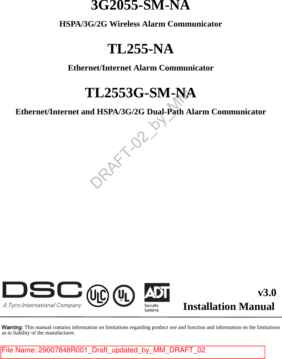
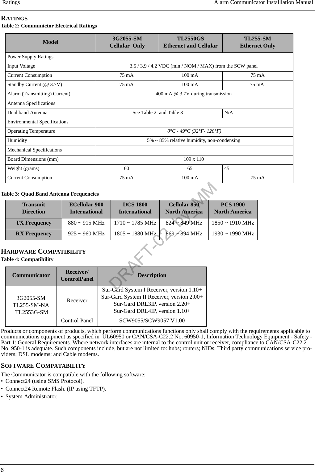
![Keypad Data Display Alarm Communicator Installlation Manual4Domain Name Service (DNS) programming is not permitted in UL/ULC listed systems.KEYPAD DATA DISPLAY•Section-Toggle Options: The number is displayed when Toggle is ON, the number is not displayed when Toggle is OFF. (e.g., Tog-gle Options displays: “[--3--6--]”. Options 3 and 6 are ON, all others are OFF). Pressing keys 1 through 8 will alternately turn the Toggle ON and OFF.•HEX/Decimal Data: Values that are provided with two defaults, separated by a / character, use the format: hexadecimal followed by decimal equivalent (e.g., Default [0BF5/3061]). Hexadecimal numbers are shown, with all leading zeroes, to the full field length defined for the number.ENTERING DATA FROM KEYPADTo enter data at the keypad, press the number key, from the table below, to select the character that you want. Pressing the number keyrepeatedly will scroll through the characters available for that key. Press the [*] key and use [<] [>] keys to scroll to one of the followingselections: (Press [*] to select the Option.)•ASCII Entry. Use this mode to enter ASCII characters from the keypad.•Clear to End. This selection will clear the remainder of the display.•Clear Display.This selection will completely erase all entries on the display.•Change Case. Toggles between upper/lower depending on current selection.NOTE: The “0” on the keypad is used to delete characters.ENTERING ASCII CHARACTERSTo enter American Standard Code for Information Interchange (ASCII) characters at the keypad, perform the following:1. Press [*] and use [<] [>] keys to scroll to “ASCII Entry”.2. Press [*] to select ASCII entry mode. 3. Use the [<] [>] keys to scroll to display the ASCII character you want to use and press [*] to accept. 4. Press [*] to exit ASCII character entry mode and return to normal entry.NOTE: Authorized access to Connect24 (3G2055-SM/TL2553G-SM) or DLS IV (TL255-SM) is required to modify any Ethernet/Cel-lular Programming Section. Specific panel Sections must be configured for proper operation of the Communicator with the panel. MOUNTING CONSIDERATIONSThe Cellular/Ethernet Communicator is fixed, wall-mounted unit and shall be installed in the location specified in these instructions.The equipment enclosure must be fully assembled and closed, with all the necessary screws/tabs and it must be secured to a wall beforeoperation. Internal wiring must be routed in a manner that prevents:• Excessive strain on wire and on terminal connections,• Interference between power limited and non power limited wiring,• Loosening of terminal connections, or• Damage of conductor insulation.WARNING: NEVER INSTALL THIS EQUIPMENT DURING A LIGHTNING STORM!The Installer must instruct the System user on each of the following items:• This manual shall be used in conjunction with the Alarm controller manual; All the safety instructions specified within that manual shall be observed. (or equivalent)• Do not attempt to service this product. Opening or removing covers may expose the user to dangerous voltages or other risks.• Any servicing shall be referred to trained service personnel only.• Use authorized accessories only with this equipment. GeneralTable 1:Data Entry at KeypadKey Value Key Value Key Value1 1-A-B-C 4 4-J-K-L 7 7-S-T-U2 2-D-E-F 5 5-M-N-O 8 8-V-W-X3 3-G-H-I 6 6-P-Q-R 9 9-Y-Z-0DRAFT-02_by_MM](https://usermanual.wiki/Tyco-Safety-Canada/113G255SM.users-manual-2/User-Guide-1510735-Page-4.png)
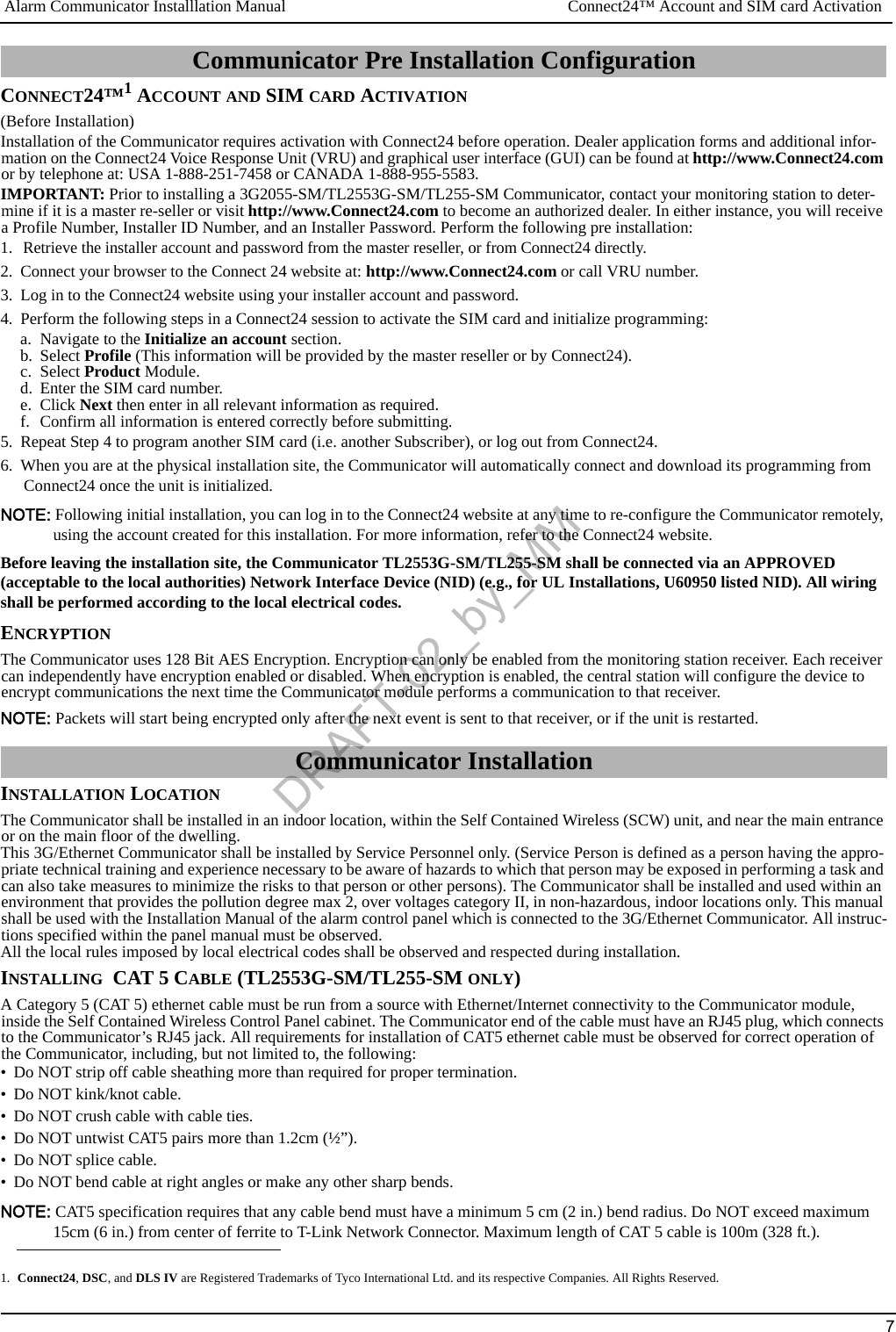
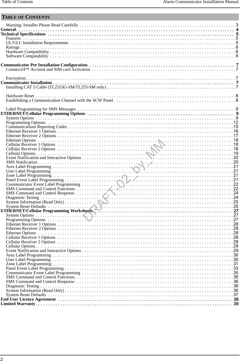
![Inserting the SIM Card Alarm Communicator Installlation Manual8Mounting HoleMounting HoleSIM Card Holder RJ-45 Connector(TL255 and TL2553G only)INSERTING THE SIM CARD1. Remove the front cover of the SCW Control Panel to access SIM holder.2. Power down the panel and disconnect the backup battery connections.3. On the SIM card holder push gently to slide the cover towards OPEN as indicated by the arrow on SIM holder. This will unlatch the SIM card holder on the side furthest from edge of the Communicator.4. Lift up the SIM card holder from the side that is not hinged.NOTE: The SIM card can be damaged by bending or scratching contacts. Use caution when handling the SIM card.5. Insert or remove the SIM card, noting the orientation of the notches on the SIM card and the SIM card holder.6. When inserting a SIM card, insert the card in the proper ori-entation and gently push the SIM card holder down and slide the holder as indicated by the arrow on SIM holder, to LOCK.7. Apply AC power to panel, and replace the panel cover.HARDWARE RESETThe Communicator can be hardware reset by installing a jumper between Pins 4 and 5 on the AUDIO/DEFAULT connector.ESTABLISHING A COMMUNICATION CHANNEL WITH THE SCW PANEL.Establishing a communication channel between the Communicator and the SCW is critical to ensuring the desired operation of the two units. The following steps must be completed during the on-site installation. Program the followingto ensure that the Communicator and the panel will work together as intended.NOTE: Panel Sections must be programmed at the panel keypad.1. Enter [*][8][Installer Code] [Section Number] for panel programming. Record any values that are modified from their default, in the appropriate Programming Worksheets.NOTE: When programming Toggle Options, the toggle is ON when the number is displayed and OFF when the number is not dis-played. (e.g., [1---5---], Toggle Options 1 and 5 are ON, all others are OFF).2. Panel Section [167] Cellular/Ethernet Interface Communications ‘Wait for ACK’: Program value as: 060 (seconds).3. When the communicator is installed with the SCW panel, 4 telephone number are available to backup one another. You can set up these 4 telephone numbers to perform in one of two ways: Backup dialling or Alternate dialling.a. Backup dialling: each of the 4 telephone numbers will make 5 dialling attempts in turn, before an FTC trouble is displayed on thekeypad. b. Alternate dialling: each telephone number makes 1 dialling attempt before moving on to the next number, cycling through eachof the 4 numbers for a total of 5 times each. If all 4 numbers fail the 5 attempts, an FTC trouble is displayed on the keypad.4. Panel Sections [301], [302], [303], and [305] can be configured as Primary communication paths.a. Panel Sections [302], [303], and [305] may also be configured for backup or redundant communications by using Panel Section(s)[383] or [351] - [376]. Refer to the SCW panel Installation Manual for more information.b. If a valid telephone number is programmed, communications will use Public Switched Telephone Network (PSTN). Entering a 4digit hexadecimal value for a telephone number will change the call routing to the Communicator, as determined by the numberprogrammed:DCAAF: Internal (All Receivers). Signals will be routed depending on Section [851] [006] programming.DCBBF: Ethernet Receiver 1 (Primary). (Not available for 3G2055-SM).DCCCF: Ethernet Receiver 2 (Backup). (Not available for 3G2055-SM).DCDDF: Cellular Receiver 1 (Primary). (Not available for TL255-SM-NA).DCEEF: Cellular Receiver 2 (Backup). (Not available for TL255-SM-NA).NOTE: Add a single ‘F’ as a suffix to the 4 digit hex number to populate the unused remainder of the 32 character field.5. Panel Section [350]: If any of the phone numbers have been programmed as DCAA, DCBB, DCCC, DCDD, or DCEE, panel Sec-tion [350] must be set to [04] if SIA format or [03] if Contact ID (CID) format.6. Panel Section [382]: Toggle Option [5], ‘GS/IP Module Enabled’, must be set to ON.7. Panel Section [401]: Toggle Option [1] must be set to ON in order to perform panel DLS session through Cellular or Ethernet.NOTE: Keep a record of the SIM card telephone number, it is required by users for SMS Command and Control functions. Due to the nature of the SIM card activation process with 3G network carriers, it can take up to 24 hours for SIM card activation to be complete. Figure 1: Layout of UA580DRAFT-02_by_MM](https://usermanual.wiki/Tyco-Safety-Canada/113G255SM.users-manual-2/User-Guide-1510735-Page-8.png)
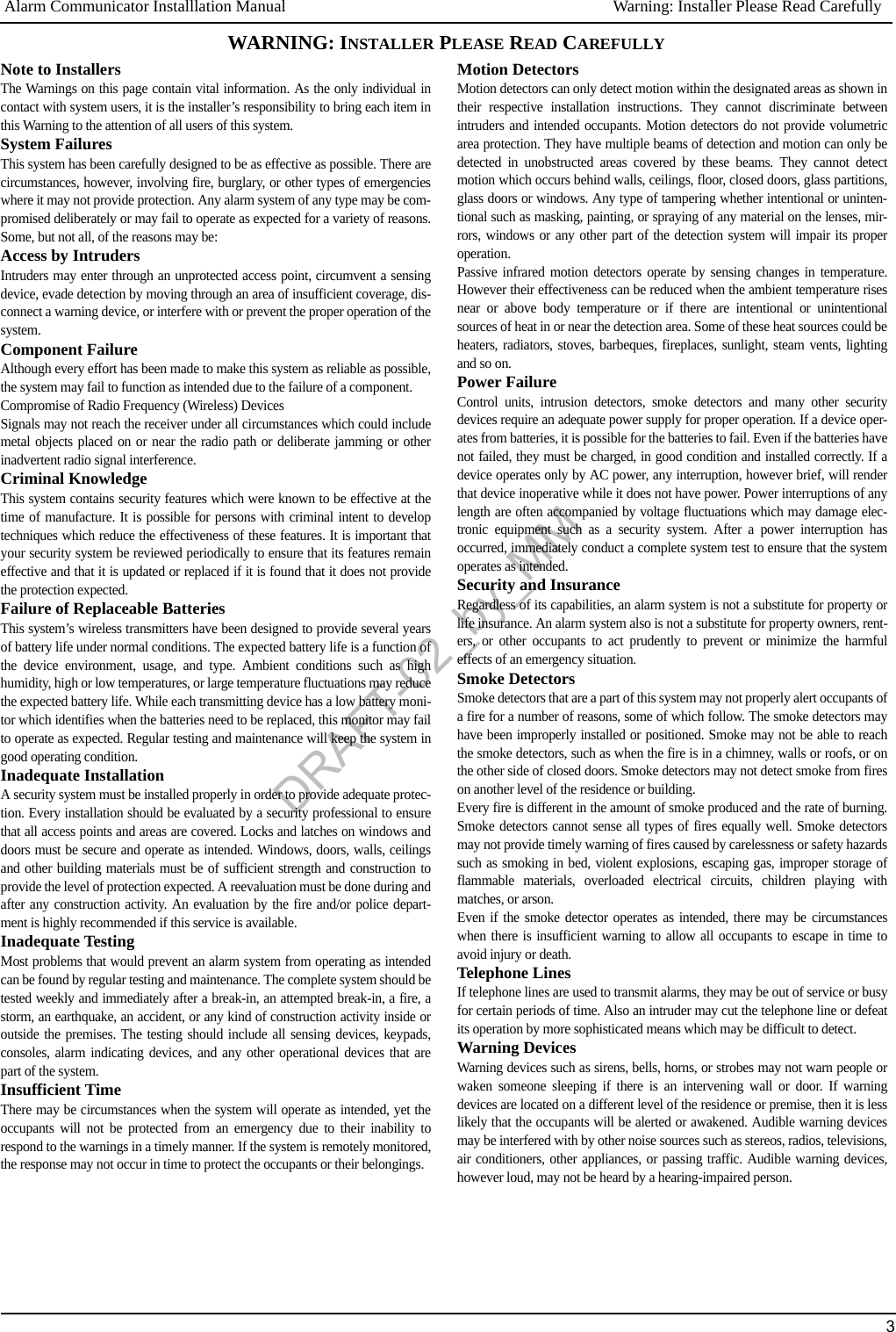
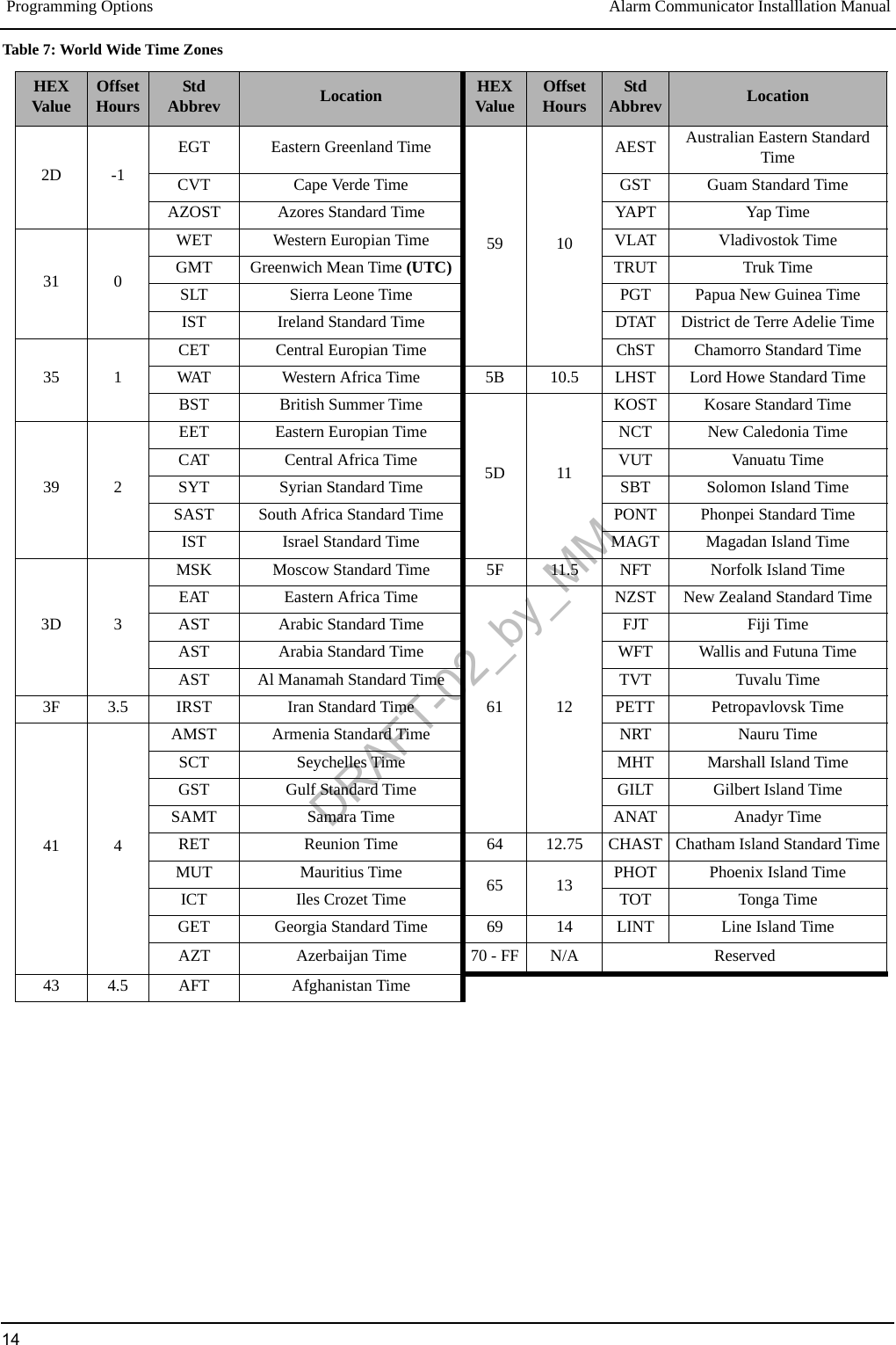
![Alarm Communicator Installlation Manual Label Programming for SMS Messages9LABEL PROGRAMMING for SMS MESSAGESProgrammable Labels can not be modified in Connect24, use DLS IV for label programming only, if labels need to be modified. Before initiating remote programming, record your network’s Public IP Address and port for incoming DLS IV connections.1. Run the DLS IV software on your computer. DLS IV will connect to the unit, using the Public IP address, and make an Ethernet con-nection. If the Ethernet connection fails, DLS IV will report an error and prompt you to connect using Cellular.NOTE: If required, download the DLS IV software from DSC: http://www.dsc.com/index.php?n=library#self. If you select the Cel-lular connection, DLS will request Connect24 to send an outgoing SMS message to the unit.2. Connect24 will confirm that the account has DLS service and will provide the Public IP address and port number of the DLS server in an SMS message.Type the SMS message text into your cell phone and send it to the Communicator’s 3G telephone number. Click OK.NOTE: The 3G phone number can be read from Communicator Section [851][996].3. SMS message will establish a connection to your computer’s DLS IV software (to change programming labels only).4. Create an account for the panel/Communicator, select the Communicator type (e.g., SMS - TL2553G-SM) and enter all relevant information in SMS section.NOTE: The 3G telephone number will also be required by the user, to send SMS Interactive messages to their system.5. Program the account information, then click Global Download and choose SMS as the Connection Type. Click OK.6. The download path configured in Programming Section [005] Toggle Option[4] determines the Cellular or Ethernet path to be used.The Programming Sections described in this document can be viewed through the panel Section for Ethernet/Cellular Programming. Enter: [*][8][installer code] [851][###], Where # # # is the 3 digit Section number referenced in this section. The Programming Worksheets at the end of this document can be used to record the new values when programming changes have been made from the default values. Programming Sections are accessed through Connect24. Installers may review/record programming Options at the panel.NOTE: Ethernet/Cellular Programming Sections accessed through the panel are for display purposes only. Configuration changes must be done using Connect24.SYSTEM OPTIONS[001] Ethernet IP AddressDefault (000.000.000.000); (TL255-SM/TL2553G-SM only)Enter the IP address of the dual Communicator. Ensure that the IP address is unique to your Communicator on the local network. For-mat is 4 fields, each field is a 3 digit decimal number. Valid range: 000-255. If an IP address is programmed in this Section, the unit will operate with Static IP (DHCP disabled). Sections [002] and [003] must also be programmed when using Static IP addresses.NOTE: Default for this Section is Dynamic Host Configuration Protocol (DHCP) enabled. When enabled, the DHCP Server will set values for: IP Address [001], Subnet Mask [002], and Gateway [003]. Programming an IP address in this Section will disable DHCP (Static IP ).[002] Ethernet IP Subnet MaskDefault (255.255.255.000); (TL255-SM/TL2553G-SM only)Enter the Ethernet IP Subnet Mask of the dual Communicator. Format is 4 fields, each field is a 3 digit decimal number. Valid range: 000-255.NOTE: If DHCP is enabled, the DHCP Server will assign the subnet mask for this Section and the programmed value will be ignored.[003] Ethernet Gateway IP AddressDefault (000.000.000.000); (TL255-SM/TL2553G-SM only)Enter the Ethernet Gateway IP address of the dual Communicator. The gateway IP address is required when a router is used on the local network to reach the destination IP address specified in Section [001]. Format is 4 fields, each field is a 3 digit decimal number. Valid range: 000-255.NOTE: If DHCP is enabled, the DHCP Server will assign the Gateway IP address for this Section and the programmed value will be ignored.[004] Receiver Supervision IntervalDefault (0087/135);When receiver supervision is enabled (ON) in Section [005] Toggle Option [3], the unit sends heartbeats to Ethernet Receiver 1 or Cel-lular Receiver 1 to test the communication path. Use this Section to set the interval time (in seconds) when heartbeats will be sent. Valid range 000A-FFFF seconds. If the programmed value is less than (000A/10) seconds, supervision is disabled.ETHERNET/Cellular Programming OptionsDRAFT-02_by_MM](https://usermanual.wiki/Tyco-Safety-Canada/113G255SM.users-manual-2/User-Guide-1510735-Page-9.png)
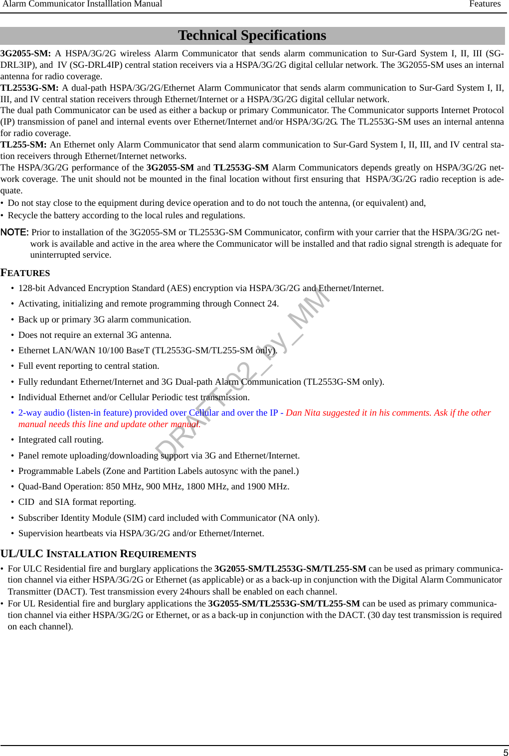
![System Options Alarm Communicator Installlation Manual10•Receiver Window: This is the supervision timeout that needs to be configured at the central station receiver.•Recommended Values: This is the recommended heartbeat interval that should be programmed into the Communicator module.• For ULC passive systems (not using heartbeat supervision), the daily test transmission must be enabled over each available communication channel Section [125] and [225]. When programming with Connect24, the recommended intervals will be programmed automatically when the required window is selected.[005] System Toggle Options[1] Ethernet Receiver 1 SupervisedDefault (OFF) (TL255-SM-NA/TL2553G-SM only).ON: Ethernet Receiver 1 will be supervised and heartbeats will be sent to Ethernet Receiver 1 based on the supervision intervalprogrammed in Section [004].OFF: Ethernet Receiver 1 will not be supervised. When disabled, heartbeat 1 is sent to the Ethernet receiver once every hour,regardless of supervision type (heartbeat 1 or 2). The heartbeat is resent every 5 seconds until ACK. If no event or heartbeat ACKis received after (Receiver Supervision Interval + 75 seconds), Supervisory trouble is indicated.NOTE: Ethernet Receiver 2 can not be supervised.[2] Cellular Receiver 1 SupervisedDefault (OFF)(3G2055-SM/TL2553G-SM only)ON: Cellular Receiver 1 will be supervised and heartbeats will be sent to Cellular Receiver 1 based on the supervision intervalprogrammed in Section [004]. If ACK to heartbeat is not received, it is retransmitted every 5 seconds. Failure to ACK 2 consec-utive heartbeats will reset the radio.OFF: Cellular Receiver 1 will not be supervised. When disabled, heartbeat is not sent to the receiver.NOTE: Cellular Receiver 2 can not be supervised.[3] Supervision TypeDefault (OFF)ON: Heartbeat 1 (Commercial Supervision). This supervision type is suitable for applications where swap detection is requiredon the supervisory packet.OFF: Heartbeat 2 (Residential Supervision). This supervision type is suitable for applications where supervision of the commu-nication path to the receiver is required. (no swap detection).NOTE: Commercial supervision is more data intensive than residential supervision and should only be used when required tomeet the approval for the installation.[4] Cellular PrimaryDefault (OFF - TL255-SM/TL2553G-SM) (ON - 3G2055-SM).ON: Cellular channel is the primary path. Ethernet channel is the secondary path, if it exists.OFF: Ethernet channel is the primary path in a dual Communicator. Cellular channel is the secondary path.NOTE: When the Communicator receives a Short Message Service (SMS) request to connect to Downloading Software (DLS),it will always use the primary path first to connect to DLS. If the primary path fails, it will use the secondary path.[5] Redundant Communications Default (OFF)(TL2553G-SM only).ON: Events will be communicated to Ethernet Receiver 1 and Cellular Receiver 1 at the same time. Events will be communi-cated to Ethernet Receiver 2 and Cellular Receiver 2 at the same time. As long as the event is successfully communicated to 1 ofthe 2 paths (Ethernet or Cellular) the Communicator will move on to the next event.NOTE: Do not configure Ethernet Receiver 1 and Cellular Receiver 1 to communicate using a common receiver configuration(i.e., identical Receiver IP address and Receiver Remote Port).OFF: Events will be communicated to the receivers individually.NOTE: This Toggle should be OFF for applications where guaranteed message delivery to both receivers is required.[6] Remote Firmware UpgradeDefault (ON).ON: The Communicator module firmware can be remotely upgraded using the Ethernet/Cellular paths.Table 5: Receiver Supervision Intervals Jurisdiction Receiver Window (Timeout) Recommended Supervision IntervalUL Commercial Burglary 200 seconds (0087/135) secondsUL Residential Fire 30 days Panel Test Transmission UL Residential Burglary 30 days Panel Test Transmission ULC Commercial Burglary Active 180 seconds (005A/90) secondsULC Commercial Burglary Passive 24 hours Panel Test Transmission ULC Commercial Fire Active 180 seconds (0073/115) secondsULC Commercial Fire Passive 24 hours Panel Test Transmission DRAFT-02_by_MM](https://usermanual.wiki/Tyco-Safety-Canada/113G255SM.users-manual-2/User-Guide-1510735-Page-10.png)
![Alarm Communicator Installlation Manual System Options11OFF:The Communicator module firmware can not be remotely upgraded. Local firmware upgrade is still possible.[7] Alternate Test Transmissions Default (OFF).ON: When the periodic test transmission interval occurs, the test transmission will alternate between being sent to the primaryand secondary receivers with each test transmission interval.OFF:When the periodic test transmission interval occurs, the test transmission will be sent to the programmed receivers, basedon the settings of the periodic test transmission reporting codes.[8] Reserved. Default (OFF).[006] System Toggle Options 2[1] Ethernet 1 Receiver Enabled. Default (ON) [OFF 3G2055-SM].ON: Ethernet Receiver 1 is enabled.OFF: Ethernet Receiver 1 is disabled.[2] Ethernet 2 Receiver Enabled. Default (ON) [OFF 3G2055-SM].ON: Ethernet Receiver 2 is enabled.OFF: Ethernet Receiver 2 is disabled.[3] Reserved. (OFF).[4] Cellular 1 Receiver Enabled. Default (ON).ON: Cellular Receiver 1 is enabled.OFF: Cellular Receiver 1 is disabled.[5] Cellular 2 Receiver Enabled. Default (ON).ON: Cellular Receiver 2 is enabled.OFF: Cellular Receiver 2 is disabled.[6] Reserved (OFF).[7] DLS Over Cellular. Default (ON). [OFF TL255-SM]NOTE: Program this toggle as OFF if you want to completely disable DLS from using the Cellular path.ON: DLS is enabled on the Cellular path.OFF: DLS is disabled on the Cellular path.NOTE: If Toggle Option [7] is OFF, DLS sessions will occur on the Ethernet path only, regardless of Primary Path set in Section[005] Toggle Option [4]. If it is ON then the Communicator will connect to the primary path first for DLS and if the ses-sion fails, the secondary path will be used.[8] Reserved. Default (ON).[007] DNS Server IP 1Default (000.000.000.000);Programming this Section is not permitted on a UL/ULC listed system.Enter the IP address for DNS Server 1. Format is 4 fields, each field is a 3 digit decimal. Valid range: 000-255.NOTE: If no value is programmed and DHCP is used, the DHCP Server will configure the address. If an address is programmed and DHCP is used, the address that you program will be used instead of the DHCP address.[008] DNS Server IP 2Programming this Section is not permitted on a UL/ULC listed system.Default (000.000.000.000);Enter the IP address for DNS Server 2. Format is 4 fields, each field is a 3 digit decimal. Valid range: 000-255.NOTE: If no value is programmed and DHCP is used, the DHCP Server will assign this value. If an address is programmed and DHCP is used, the address that you program will be used instead of the DHCP address.[009] LanguageDefault (01);NOTE: Immediately after programming this Section, perform a Default Languages in Section [999][11] to have programmable labels available in the selected language. Programming this Section with an invalid language number will default to English [01]. Connect24 will automatically update all programmable language labels when this Section is changed.Table 6: Label LanguagesOPT Language OPT Language OPT Language OPT Language00 Reserved 08 Czech 16 Turkish 24 Lithuanian01 English 09 Finnish 17 Reserved 25 Ukrainian 02 Spanish 10 German 18 Croatian 26 Slovakian03 Portuguese 11 Swedish 19 Hungarian 27 Serbian 04 French 12 Norwegian 20 Romanian 28 Estonian 05 Italian 13 Danish 21 Russian 29 Slovenian 06 Dutch 14 Hebrew 22 Bulgarian 30-99 Reserved07 Polish 15 Greek 23 LatvianDRAFT-02_by_MM](https://usermanual.wiki/Tyco-Safety-Canada/113G255SM.users-manual-2/User-Guide-1510735-Page-11.png)
![Programming Options Alarm Communicator Installlation Manual12[010] System Toggle Options 3Default (OFF)[1] Two way Audio over Cellular.ON: Two way audio over the Cellular Voice channel is enabled.OFF: Two way audio over the Cellular Voice channel is disabled.[2]-[8] Reserved. Default (OFF)PROGRAMMING OPTIONS[011] Installer CodeDefault (CAFE);Program your installer code for this Communicator module. The installer code will be required when programming the Communicator module. Valid range: 0000 - FFFF.[012] DLS Incoming PortDefault (0BF6/3062);The DLS Incoming Local Port (listening port) is the port DLS IV will use when connecting to the Communicator. If a router or gateway is used, it must be programmed with a Transmission Control Protocol (TCP) port forward for this port to the Communicator module IP address. Valid range: 0000-FFFF.[013] DLS Outgoing PortDefault (0BFA/3066);The DLS Outgoing Port is used for outgoing session to DLS IV after an SMS request has been sent to the Communicator. Use this Sec-tion to set the value of the local outgoing port. The value must be changed if the Communicator is located behind a firewall and must be assigned a particular port number, as determined by your network administrator. In most cases, changing the default value or configur-ing your firewall with this port is not required. Valid range: 0000-FFFF.NOTE: If Section [006] Toggle Option [7] is ON. DLS will use the primary path for session. If Section [006] Toggle Option [7] is OFF DLS will use the Ethernet path, if available.[020] Time ZoneDefault (00)Use Column 2 (Offset Hours) to find your local Time Zone. Record the two digit HEX value from Column 1 (HEX Value) on the same row. Program this HEX value for your Time Zone. Valid range is 00 - FF.Table 7: World Wide Time ZonesHEXValue OffsetHours StdAbbrev Location HEXValue OffsetHours StdAbbrev Location01 -12 BIT Baker Island Time 47 5.5 IST Indian Standard Time05 -11 NUT Niue Time 48 5.75 NPT Nepal TimeSST Somoa Standard Time49 6XJT Xinjiang Standard Time09 -10HAST Hawaii-Aleutian Standard Time EKST East Kazakhstan Standard TimeTHAT Tahiti Time LKT Sri Lanka TimeTKT Tokelau Time VOST Vostok TimeCKT Cook Island Time OMSK Omsk Standard Time0B -9.5 MIT Marquesas Island Time NOVT Novosibirsk Time0D -9 AKST Alaska Standard Time BTT Bhutan TimeGIT Gambier Island Time BIOT British Indian Ocean Time11 -8PST Pacific Standard Time 4B 6.5 CCT Cococ Islands TimePST Pitcarirn Standard Time MMT Myanmar TimeCIST Clipperton Island Standard Time4D 7CXT Christmas Island Time15 -7 MST Mountain Standard Time KOVT Khovd Time19 -6CST Central Standard Time KRAT Krasnoyarsk TimeGALT Galapagos Time WIB Waktu Indonesia Bagian BaratPIT Peter Island Time ICT Indochina TimeEAST Easter Island Standard Time BDT Bangladesh Standard TimeDRAFT-02_by_MM](https://usermanual.wiki/Tyco-Safety-Canada/113G255SM.users-manual-2/User-Guide-1510735-Page-12.png)

![Alarm Communicator Installlation Manual Communications Reporting Codes15[021] Account CodeDefault (FFFFFF);The account code is included when transmitting any events generated by the Communicator. (e.g., Panel Absent Trouble). It is recom-mended that the account code be the same as the control panel account number. Valid range: 000001-FFFFFE. If 4 digit account codes are needed the 2 lowest digits shall be programmed as FF;( e.g., Account 1234 is programmed as:1234FF). Programming this Section as all 0 or all F will cause a Module Configuration Trouble (yellow LED=12 flashes).[022] Communications FormatDefault (04);Program 03 for Contact ID (CID). Program 04 for SIA. Communicator will synchronize with the panel and use the same communica-tion format as the panel regardless of the value set in this Section.The module can be configured to send internal events in SIA or CID format. The SIA communication format follows the level 2 speci-fications of the SIA Digital Communication Standard - October 1997. This format will send the account code along with its data trans-mission. The transmission will look similar to the following at the receiver: Nri0 ET001Where: N = New Event; ri0 = Partition/Area identifier; ET = Panel Absent Trouble; 001 = Zone 001.COMMUNICATIONS REPORTING CODES[023] Panel Absent TroubleDefault (FF)Program 00 to disable this event or FF to enable. This event will occur when communications with the panel have been lost for more than 60 seconds.[024] Panel Absent Trouble RestoreDefault (FF);Program 00 to disable this event or FF to enable. This event will occur when communications with the control panel have resumed.45 5CAST Chinese Atlantic Standard TimeWKST West Kazakhstan Standard TimePKT Pakistan TimeYEKT Yekaterinburg TimeUZT Uzbekistan TimeTMT Turkmenistan TimeTJT Tajikistan TimeTFT French Southern and Antarctic TimeMVT Maldives TimeMAWT Mawson TimeKGT Kyrgyzstan TimeHMT Heard and McDonald Island TimeDAVT Davis TimeTable 8: Event Reporting CodesEvent SIA IdentifierSIA Reporting CodeCID Qualifier CID Event CodeCID Reporting CodeCID User/Zone[023] Panel Absent Trouble ET 001 1 3 55 001[024] Panel Absent Trouble Restore ER 001 3 3 55 001[025] Radio Activation Restore RS 001 3 5 52 001[026] Ethernet1 Test Transmission RP 001 1 6 A3 951[027] Ethernet2 Test Transmission RP 002 1 6 A3 952[028] Cellular1 Test Transmission RP 003 1 6 A3 955[029] Cellular2 Test Transmission RP 004 1 6 A3 956[030] FTC Restore YK 001 3 3 54 001Table 7: World Wide Time ZonesHEXValue OffsetHours StdAbbrev Location HEXValue OffsetHours StdAbbrev LocationDRAFT-02_by_MM](https://usermanual.wiki/Tyco-Safety-Canada/113G255SM.users-manual-2/User-Guide-1510735-Page-15.png)
![Ethernet Receiver 1 Options Alarm Communicator Installlation Manual16[025] Radio Activation RestoreDefault (FF);Program 00 to disable this event or FF to enable. This event will occur after any successful Connect24 programming session.System Test Options [026 - 029]Test Transmissions to Primary Receiver, with Backup to Secondary Receiver:Set Ethernet Section [026] to (FF) and Section [027] to (00). Set Cellular Section [028] to (FF) and Section [029] to (00).• If the test transmission fails to the primary receiver it will backup to the secondary receiver.• If the test transmission fails to the secondary receiver an FTC trouble will be generated.Test Transmission Unique to Primary and Secondary Receivers:Set Ethernet Section [026] to (FF) and Section [027] to (FF). Set Cellular Section [028] to (FF) and Section [029] to (FF).• The module will send periodic test transmissions to each receiver independently, with no backups.• If the test transmission fails to any of the programmed receivers, an FTC trouble will be generated.Alternate Test TransmissionAlternate Test Transmission can be enabled or disabled in Section [005] Toggle Option [7].[026] Ethernet 1 TransmissionDefault (FF);Program 00 to disable this event transmission or FF to enable. See System Test Options (above) for details on settings.[027] Ethernet 2 TransmissionDefault (00);Program 00 to disable this event transmission or FF to enable. See System Test Options (above) for details on settings.[028] Cellular 1 TransmissionDefault (FF);Program 00 to disable this event transmission or FF to enable. See System Test Options (above) for details on settings.[029] Cellular 2 TransmissionDefault (00);Program 00 to disable this event transmission or FF to enable. See System Test Options (above) for details on settings.NOTE: Interval (in minutes) between periodic tests is programmed in Section [125] (Ethernet) and Section [225] (Cellular).[030] FTC RestoreDefault (FF);Program 00 to disable or FF to enable. This event will occur when an FTC Trouble on the system restores.[031] Panel Tamper AlarmDefault (FF);Program 00 to disable this event transmission or FF to enable. This event will occur when a Panel Tamper occurs on the system.Setting this option to 00 will disable monitoring of the tamper switch. See Table 12 for SIA and CID reporting codes.[032] Panel Tamper Alarm RestoreDefault (FF);Program 00 to disable this event transmission or FF to enable. This event will occur when a Panel Tamper event on the system restores. See Table 9 for SIA and CID reporting codes.ETHERNET RECEIVER 1 OPTIONS(TL255-SM/TL2553G-SM only)[101] Ethernet Receiver 1 Account CodeDefault (0000000000);The account code is used by the central station to distinguish between transmitters. This account code is used when transmitting heart-beat signals to the central station receiver. Signals received from the control panel will use the control panel account number. Valid range: 0000000001-FFFFFFFFFE. Programming this Section as all 0 or all F will cause a Module Configuration Trouble (yellow LED=12 flashes).NOTE: If Ethernet Receiver 1 and Cellular Receiver 1 are programmed as the same receiver (IP and port number are identical), Ether-net Receiver 1 account code will be used.[102] Ethernet Receiver 1 DNISDefault (000000);The Dialled Number Information Service (DNIS) is used in addition to the Account Code to identify the Communicator module at the central station. Valid range: 000000 - 099999. Value is entered as a leading 0 followed by the 5 digit DNIS. Format is Binary Coded Decimal (BCD).NOTE: Each Ethernet/Cellular receiver must be programmed with a unique DNIS.Table 9: Panel Tamper Reporting CodesEvent SIA Identifier SIA Reporting Code CIDQualifier CIDEvent Code CIDReporting CodeCIDUser/ZonePanel Tamper ES 001 1 1 45 001Panel Tamper Restore EJ 001 3 1 45 001DRAFT-02_by_MM](https://usermanual.wiki/Tyco-Safety-Canada/113G255SM.users-manual-2/User-Guide-1510735-Page-16.png)
![Alarm Communicator Installlation Manual Ethernet Receiver 2 Options17[103] Ethernet Receiver 1 AddressDefault (127.000.000.001);The default address enables the Communicator to operate in Unattended Mode.Unattended Mode is used when a receiver is not available and the unit is required to perform DLS sessions.Typically used where the customer programs the control panel daily due to access control and still wants to receive alarms without buying extra hardware (receiver) or software.NOTE: When a valid IP address has been programmed, Ethernet Receiver 1 is enabled and will communicate events over the Ethernet channel.Ethernet Receiver 1 and Cellular Receiver 1 may be configured to communicate to the same central station receiver. To configure the device to operate using this Common Receiver Mode functionality, program Ethernet Receiver 1 and Cellular Receiver 1, IP address and port number with identical values.NOTE: When operating in Common Receiver Mode, Ethernet Receiver 1 account code will be used for Ethernet/Cellular.[104] Ethernet Receiver 1 Remote PortDefault (0BF5/3061);This Section determines the remote port of Ethernet receiver 1. Valid range: 0000 - FFFF.[105] Ethernet Receiver 1 Local PortDefault (0BF4/3060);Use this Section to set the value of the local outgoing port. Set the value of this port when your installation is located behind a firewall and must be assigned a particular port number as determined by your central station system administrator. Valid range: 0000 - FFFF.[106] Ethernet Receiver 1 Domain NameDefault ( );Enter the Domain Name as 32 ASCII characters.Programming this Section is not permitted on a UL/ULC listed system.ETHERNET RECEIVER 2 OPTIONS(TL255-SM/TL2553G-SM only)[111] Ethernet Receiver 2 Account CodeDefault (0000000000);The account code is used by the central station to distinguish between transmitters. The account code is used when transmitting heart-beat signals to the central station receiver. Signals received from the control panel will use the control panel account number. Valid range: 0000000001- FFFFFFFFFE. Programming this Section as all 0 or all F will cause a Module Configuration Trouble (yellow LED=12 flashes).NOTE: If both Ethernet Receiver 2 and Cellular Receiver 2 are the same receiver (IP and port number are identical), Ethernet Receiver 2 account will be used for Ethernet and Cellular.[112] Ethernet Receiver 2 DNISDefault (000000);The DNIS is used in addition to the account code to identify the Communicator module at the central station. Valid range: 000000 - 099999. Value is entered as leading 0 followed by 5 digit DNIS. Format is BCD.NOTE: Each Ethernet/Cellular receiver must be programmed with a unique DNIS.[113] Ethernet Receiver 2 AddressDefault (000.000.000.000);Programming the Ethernet receiver 2 IP address with 000.000.000.000 will disable Ethernet.Enter the Ethernet receiver 2 IP address. This address will be provided by your central station system administrator. Format is 4 fields, each field is a 3 digit decimal. Valid range: 000-255.NOTE: When a valid IP address has been programmed, Ethernet Receiver 2 is enabled and will communicate events over the Ethernet channel.Ethernet Receiver 2 and Cellular Receiver 2 may be configured to communicate to the same central station receiver. To configure the device to operate using this common receiver mode functionality, program the Ethernet Receiver 2 and Cellular Receiver 2, IP address and port number with the same values. When operating in common receiver mode the Ethernet Receiver 2 account code will be used for communications over Ethernet and Cellular.NOTE: Do not program Ethernet Receiver 1 and Ethernet Receiver 2 to communicate to the same receiver.[114] Ethernet Receiver 2 Remote PortDefault (0BF5/3061);This Section is used to program the port number used by Ethernet Receiver 2. Set the value of this port when your installation is located behind a firewall, and must be assigned a particular port number as determined by your central station system administrator. Valid range: 0000 - FFFF.NOTE: Do not program Ethernet Receiver 1 and Ethernet Receiver 2 Port with the same value.[115] Ethernet Receiver 2 Local PortDefault (0BF9/3065);Use this Section to program the value of the local outgoing port. You can set the value of this port when your installation is located behind a firewall and must be assigned a particular port number as determined by your network administrator. Valid range: 0000 - FFFF. NOTE: Do not program Ethernet Receiver 1 and Ethernet Receiver 2 Port with the same value.DRAFT-02_by_MM](https://usermanual.wiki/Tyco-Safety-Canada/113G255SM.users-manual-2/User-Guide-1510735-Page-17.png)
![Ethernet Options Alarm Communicator Installlation Manual18[116] Ethernet Receiver 2 Domain NameDefault ( );Programming this Section is not permitted on a UL/ULC listed system.Enter the Domain Name as 32 Character ASCII.ETHERNET OPTIONS(TL255-SM-NA/TL2553G-SM only)[124] Ethernet Test Transmission TimeDefault (9999);Enter a 4 digit number (0000-2359) using the 24-hour clock format (HHMM) to set the test transmission time of day. Valid range: 00 -23 hours (HH) and 00 - 59 minutes (MM). Programming a value of (9999) will disable the test transmission time.NOTE: The internal date and time will automatically be programmed when the unit communicates with the primary receiver.[125] Ethernet Test Transmission CycleDefault (000000);This value represents the interval between test transmissions, in minutes. Valid range: 000000 - 999999 minutes. Once the unit has sent the initial periodic test transmission, all future test transmissions will be offset by the programmed number of minutes. See Sections [026-029].NOTE: Minimum value is 000005 minutes. Programming intervals less than 5 minutes will disable test transmission.CELLULAR RECEIVER 1 OPTIONS(3G2055-SM/TL2553G-SM only)[201] Cellular Receiver 1 Account CodeDefault (0000000000);The account code is used by the central station to distinguish between transmitters. This account code is used when transmitting heart-beat signals to the central station receiver. Signals received from the control panel will use the control panel account number. Valid range: 0000000001 - FFFFFFFFFE. Programming this Section as all 0 or all F will cause a Module Configuration Trouble (yellow LED = 12 flashes).[202] Cellular Receiver 1 DNISDefault (000000);The DNIS is used in addition to the account code to identify the Communicator module at the central station. Valid range: 000000 - 099999. Values are entered as leading 0 followed by five digits. Format is BCD.NOTE: Each Ethernet/Cellular receiver must be programmed with a unique DNIS.[203] Cellular Receiver 1 AddressDefault (000.000.000.000)Enter the Cellular Receiver 1 IP address. This information will be provided by your central station system administrator. Each 3 digit segment of the address must be within a valid range of 000-255.NOTE: When a valid IP address has been entered, the Cellular is enabled and will communicate events over the Cellular channel.[204] Cellular Receiver 1 PortDefault (0BF5/3061);This Section determines the port used by Cellular Receiver 1. Change the default value of this port when your installation is located behind a firewall, and must be assigned a particular port number as determined by your central station system administrator. Valid range: 0001 - FFFF.NOTE: Programming a value of 0000 will disable the receiver.[205] Cellular Receiver 1 APNDefault ( )The Access Point Name (APN) determines the Cellular network that the Communicator will connect to. This information is available from your network carrier. Program this Section as 32 ASCII characters.NOTE: When a SIM card with a custom APN is used, the unit will not have access to the internet. DLS and remote flash can still be done if Section [221] is programmed with a valid Public APN.[206] Cellular Receiver 1 Domain NameDefault ( );Programming this Section is not permitted on a UL/ULC listed system.Enter the Domain Name as 32 ASCII characters. This information will be provided by your central station system administrator.CELLULAR RECEIVER 2 OPTIONS(3G2055-SM/TL2553G-SM only)Table 10: Ethernet Test Transmission IntervalTest Transmission Interval Daily Weekly MonthlyProgrammed Minutes 001440 010080 043200DRAFT-02_by_MM](https://usermanual.wiki/Tyco-Safety-Canada/113G255SM.users-manual-2/User-Guide-1510735-Page-18.png)
![Alarm Communicator Installlation Manual Cellular Options19[211] Cellular Receiver 2 Account CodeDefault (0000000000);The account code is used by the central station to distinguish between different transmitters. This account code is used when transmit-ting signals to the central station receiver. Signals received on the control panel will use the control panel account number. Valid range: 0000000001 - FFFFFFFFFE. Programming this Section as all 0 or all F will cause a Module Configuration Trouble (yellow LED = 12 flashes).[212] Cellular Receiver 2 DNISDefault (000000);The DNIS is used in addition to the Account Code to identify the Communicator module at the central station. Valid range: 000000 - 099999. Values are entered as a 0 followed by the 5 digit DNIS value. Format is BCD.NOTE: Each Ethernet/Cellular receiver must be programmed with a unique DNIS.[213] Cellular Receiver 2 AddressDefault (000.000.000.000);Enter the Cellular Receiver 2 IP address. This IP address will be provided by your central station. Format is 4 fields, each field is 3 digit decimal. Valid range: 000 - 255.NOTE: When a valid address has been entered, Cellular Receiver 2 is enabled and will communicate events over the Cellular path.[214] Cellular Receiver 2 PortDefault (0BF5/3061);This Section defines the port of Cellular Receiver 2. Change the value of this port when your installation is located behind a firewall, and must be assigned a particular port number, as determined by your central station system administrator. Valid range: 0000 - FFFF.NOTE: Do not program Cellular Receiver 1 and Cellular Receiver 2 to communicate to the same receiver.[215] Cellular Receiver 2 APNDefault ( );The APN determines the Cellular network that the Communicator will connect to. This information is available from your network car-rier. Program this Section with up to 32 ASCII characters.NOTE: When a SIM card with a custom APN is used, the unit will not have access to the internet. DLS and remote flash can still be done if Section [221] is programmed with a valid Public APN.[216] Cellular Receiver 2 Domain NameDefault ( );Programming this Section is not permitted on a UL/ULC listed system.Enter the Cellular Receiver 2 Domain Name with up to 32 ASCII characters.CELLULAR OPTIONS(3G2055-SM/TL2553G-SM only)[221] Cellular Public Access Point NameDefault ( );When the Communicator is operating on a private APN, use this Section to select a public APN for DLS and Remote Firmware Update. This information is available from your network carrier. The APN identifies public Cellular network that the Communicator will con-nect to.[222] Cellular Login User NameDefault ( );Some network carriers require you to provide login credentials when connecting to an APN. Program your login User name here. For-mat is up to 32 ASCII characters.[223] Cellular Login PasswordDefault ( );Some network carriers require you to provide login credentials when connecting to an APN. Program your login password here.Format is up to 32 ASCII characters.[224] Cellular Test Transmission Time of DayDefault (9999);Enter a 4 digit value using the 24-hour clock format (HHMM) to set the test transmission time of day. Valid range: 00-23 for the hours (HH) and 00-59 for the minutes (MM).NOTE: To disable the test transmission time of day enter 9999 or FFFF in this Section.The internal date and time will be automatically programmed by the primary receiver only.[225] Cellular Test Transmission CycleDefault (000000);This value represents the interval in between test transmissions in minutes. Valid range: 000000 - 999999 minutes. Once the unit has sent the initial periodic test transmission, all future test transmissions will be offset by the programmed number of minutes. See Sec-tions [026 - 029].NOTE: Minimum value is 000005 minutes. Programming an interval that is less than 5 minutes will disable test transmission.Table 11: Cellular Test Transmission IntervalTest Transmission Interval Daily Weekly MonthlyProgrammed Minutes 001440 010080 043200DRAFT-02_by_MM](https://usermanual.wiki/Tyco-Safety-Canada/113G255SM.users-manual-2/User-Guide-1510735-Page-19.png)
![Event Notification and Interactive Options Alarm Communicator Installlation Manual20[226] Cellular Trouble DelayDefault (00);This option is used to program the delay, in minutes, for reporting a Cellular Trouble Delay. Valid entries are 00 - FF. (e.g., for a 10 minute Cellular Trouble Delay enter 0A). There is no delay if value is programmed as 00.[227] Voice Call TimeoutDefault (00);This option sets the Voice Call Timeout, in minutes. Programming a value of 00 will disable timeout. Valid range is 00 to FF.[228] Voice Call Back TimeDefault (0A);This option sets the Voice call back time, in minutes. When the Communicator requests Call Back from the receiver, it will answer incoming calls during the programmed timeout period. If an incoming call is received after the timeout from requesting call back, the Communicator will answer the call and immediately hang up. Programming a value of 00 will disable timeout (accept all incoming calls). Default value is 0A/10 seconds. Valid range is 00 to FF.[229] Voice Call Back NumberDefault (SIM Telephone Number);This option sets the Voice Call Back Telephone Number for the receiver. This number is used for Two Way calling. Current SIM tele-phone number can be viewed in Section [996]. Valid entry is 32 character ASCII.EVENT NOTIFICATION AND INTERACTIVE OPTIONS[301] Command and Control Toggle Options[1] SMS Notification Default (ON).[2] Reserved Default (OFF).[3] SMS Command and Control Default (ON).[4] Interactive Default (ON).[5] SMS Character Format Default (See Table 12 below for default by language selection).ON: SMS Unicode, maximum message length is 70 characters.OFF: 7 bit SMS, maximum message length is 160 characters.[6] Long SMS Message Handling Default (OFF);ON: If longer than maximum message length, it is split and sent as multiple SMS messages.OFF: If longer than maximum message length. A single, truncated SMS message is sent.[7-8]Reserved Default (OFF).[311] - [318] SMS Phone Number 1 - 8Default ( );These Sections may be programmed through DLS IV or the keypad. Up to 8 SMS telephone numbers (4 - 32 digits) can be programmed in Section [31x] Where x is an SMS telephone number from 1 to 8. Leaving programming blank for a telephone number will disable that number. The User can program their own mobile telephone numbers at the keypad using [*] [6] <> “SMS Programming”. The SMS Command and Control feature utilize the SMS messaging service provided by the Cellular network and is subject to the limitations of SMS messaging. These limitations include delayed messages and lack of guaranteed deliv-ery.NOTE: SMS Command and Control (Sections [601] - [618] will only process messages from the mobile telephone numbers pro-grammed in this Section if SMS Command and Control is enabled [301][ 3] ON. SMS responses are listed in Sections [621] - [630]. A blank telephone number is disabled.SMS NOTIFICATION[321] - [328] SMS Phone Number 1 - 8 Toggle OptionsThe toggles in this Section determine the type of event message that will be sent to the SMS number programmed in Sections [311] - [318].[1] SMS Notification Alarm/Restore Default (ON).[2] SMS Notification Tamper/Restore Default (ON).[3] SMS Notification Opening/Closing Default (ON).[4] SMS Notification System Maintenance Default (ON).[5] SMS Notification System Test Default (ON).[6] SMS Notification Internal Events Default (ON).[7] SMS Notification Enabled Default (ON).Table 12: Event Notification LanguageLanguage Default Language Default Language Default Language DefaultEnglish OFF Czech ON Greek ON Latvian OFFSpanish OFF Finnish OFF Turkish OFF Lithuanian OFFPortuguese OFF German OFF Croatian ON Ukrainian ONFrench OFF Swedish OFF Hungarian ON Slovakian OFFItalian OFF Norwegian OFF Romanian OFF Serbian ONDutch OFF Danish OFF Russian ON Estonian OFFPolish ON Hebrew ON Bulgarian ON Slovenian OFFDRAFT-02_by_MM](https://usermanual.wiki/Tyco-Safety-Canada/113G255SM.users-manual-2/User-Guide-1510735-Page-20.png)
![Alarm Communicator Installlation Manual Area Label Programming21[8] SMS Command and Control Enabled Default (ON).NOTE: Each telephone number can be programmed to receive different event notifications. When more than 1 number receives the event, the system will send the message to phone number 1 first. Only 1 send attempt is made for each programmed number. Notification, for each programmed telephone number can be enabled/disabled with Toggle Option [7].AREA LABEL PROGRAMMINGEach Area label is up to 32 ASCII characters, including spaces. The label language is specified in Section [009].[351] Account LabelDefault (Security System);The Account Label is up to 32 ASCII characters. It is sent at the beginning of every SMS message originating from the Communicator module.This label is used to identify the system to the recipient of the SMS message.[352] System LabelDefault (System Area);The System Label is up to 32 ASCII characters. It is used for notification messages that apply to the system.NOTE: On single partition systems the System Label may be used for all messages.[353] - [360] Partition 1- 8 LabelDefault (Partition x);Where x is a partition number from 1 - 8. Partition Labels are up to 32 ASCII characters. Labels are used for SMS notification messages that apply to a specific partition on the system.USER LABEL PROGRAMMING[361] - [400] User 1 - 40 LabelDefault (User x);Where x is the User number from 1 - 40. User labels are used to identify a User for SMS notification messages that apply to a specific user. There are 40 programmable User Labels. Each label is up to 16 ASCII characters. The label language is specified in Section [009].ZONE LABEL PROGRAMMING[401] - [464] Zone 1 - 64 Label Default (Zone n); Where n is a Zone number from 1 - 64. Zone Labels are up to 32 ASCII characters. Labels are used to identify the Zone for notification messages that apply to a specific Zone. The label language is specified in Section [009]. Zone labels are numbered 1 - 64 and Zones are numbered 1-128. No labels are assigned to Zones 65-128.PANEL EVENT LABEL PROGRAMMING[501] - [580] Event Labels Default (see Default Label in Table 13 );There are 80 programmable Event labels. Each label is pre programmed with the default text shown in Table 13 .Each label is up to 32 ASCII characters (including spaces). The language is specified in Section [009]. Table 13: Panel Event LabelsEvent [Section] Label Default Label Event [Section] Label Default Label[501] Burglary Alarm [Burglary Alarm] [502] Burglary Alarm Restore [Burglary Alarm Restore][503] Fire Alarm [Fire Alarm] [504] Fire Alarm Restore [Fire Alarm Restore][505] 24 Hour Alarm [24 Hour Alarm] [506] 24 Hour Alarm Restore [24 Hour Alarm Restore][507] Holdup Alarm [Holdup Alarm] [508] Holdup Alarm Restore [Holdup Alarm Restore][509] Gas Alarm [Gas / Carbon Monoxide Alarm] [510] Gas Alarm Restore [Gas / Carbon Monoxide Restore][511] Heat Alarm [High Temperature Alarm] [512] Heat Alarm Restore [High Temperature Alarm Restore][513] Medical Alarm [Medical Alarm] [514] Medical Alarm Restore [Medical Alarm Restore][515] Panic Alarm [Panic Alarm] [516] Panic Alarm Restore [Panic Alarm Restore][517] Emergency Alarm [Emergency Alarm] [518] Emergency Alarm Restore [Emergency Alarm Restore][519] Sprinkler Alarm [Sprinkler Alarm] [520] Sprinkler Alarm Restore [Sprinkler Alarm Restore][521] Water Level Alarm [Water Level Alarm] [522] Water Level Alarm Restore [Water Level Alarm Restore][523] Freeze Alarm [Low Temperature Alarm] [524] Freeze Alarm Restore [Low Temperature Alarm Restore][525] Fire Supervisory [Fire Supervisory] [526] Fire Supervisory Restore [Fire Supervisory Restore][527] Zone Tamper [Zone Tamper] [528] Zone Tamper Restore [Zone Tamper Restore][529] Zone Fault [Zone Fault] [530] Zone Fault Restore [Zone Fault Restore]DRAFT-02_by_MM](https://usermanual.wiki/Tyco-Safety-Canada/113G255SM.users-manual-2/User-Guide-1510735-Page-21.png)
![Communicator Event Label Programming Alarm Communicator Installlation Manual22COMMUNICATOR EVENT LABEL PROGRAMMINGSMS COMMAND AND CONTROL FUNCTIONSUsers can send SMS text messages from their mobile phone to the Cellular phone number assigned to their system. Commands are only accepted from telephone numbers that have been programmed in Sections [311]-[318]. The system will reject messages sent from tele-phone numbers that are not on the programmed list.When the received SMS text matches a valid Section message, the function is performed on the control panel. Text messages are not case sensitive and extra spaces are ignored. A User Access Code may be required for some SMS messages.[531] Fire Trouble [Fire Trouble] [532] Fire Trouble Restore [Fire Trouble Restore][533] Module Supervisory [Module Supervisory Trouble][534] Module Supervisory Restore [Module Supervisory Restore][535] General System Tamper [General System Tamper] [536] General System Tamper Restore [General System Tamper Restore][537] Wireless Device Low Battery [Wireless Device Low Battery][538] Wireless Device Low Bat-tery Restore [Wireless Device Battery Restore][539] Cross Zone/Police Code [Burglary Verified] [540] Burglary Not Verified [Burglary Not Verified][541] Duress Alarm [Duress Alarm] [542] Opening After Alarm [Disarmed After Alarm][543] Recent Closing [Alarm Occurred After Arming] [544] Alarm Canceled [Alarm Canceled][545] Keypad Lockout [Keypad Lockout] [546] Exit Fault [Exit Fault][547] Partial Closing [Armed With Zones Bypassed] [548] Zone Bypass [Zone Bypassed][549] Zone Unbypass [Zone Unbypassed] [550] Auto Arm Cancel [Automatic Arming Cancelled][551] Closing [Armed By] [552] Opening Label [Disarmed By][553] Special Closing [Armed] [554] Special Opening [Disarmed][555] Late to Open [Late to Open] [556] Delinquency [Delinquency][557] General System Trouble [General System Trouble] [558] General System Trouble Restore [General System Trouble Restore][559] AC Line Trouble [AC Power Failure] [560] AC Line Trouble Restore [AC Power Restore][561] Battery Trouble [Battery Trouble] [562] Battery Trouble Restore [Battery Restore][563] Bell Circuit Trouble [Bell Circuit Trouble] [564] Bell Circuit Trouble Restore [Bell Circuit Restore][565] Auxiliary Power Trou-ble [Auxiliary Power Trouble] [566] Auxiliary Power Trouble Restore [Auxiliary Power Restore][567] Ground Fault [Ground Fault Trouble] [568] Ground Fault Restore [Ground Fault Restore][569] TLM Failure [Telephone Line Failure] [570] TLM Failure Restore [Telephone Line Restore][571] FTC Trouble [Fail To Communicate Trouble] [572] FTC Restore [Fail To Communicate Restore][573] Event Buffer 75% Full [Event Buffer Near Full] [574] DLS Lead In [Remote Programming Begin][575] DLS Lead Out [Remote Programming End] [576] Installer Lead In [Local Programming Begin][577] Installer Lead Out [Local Programming End] [578] Walk Test Lead In [Walk Test Begin][579] Walk Test Lead Out [Walk Test End] [580] System Test [System Test Message]Table 14: Communicator Event Label Event Section Label Default Label Event Section Label Default Label[591] Panel Absent Trouble [Panel Communications Trouble] [592] Panel Absent Trouble Restore [Panel Communications Restored][593] Module Reprogramming[Communicator Programming Updated] [594] Firmware Update [Communicator Firmware Updated]Table 13: Panel Event LabelsEvent [Section] Label Default Label Event [Section] Label Default LabelDRAFT-02_by_MM](https://usermanual.wiki/Tyco-Safety-Canada/113G255SM.users-manual-2/User-Guide-1510735-Page-22.png)
![Alarm Communicator Installlation Manual SMS Command and Control Functions23The User can send just the partition number or the complete label.(e.g., “Away arm Partition 2 1234” is treated the same as “away arm 2 1234 ”).The SMS Message format is in 3 parts: Command, Partition Label (or only the partition number), and Access Code.• If an Access Code is included in the message, it is sent to the control panel for validation, along with the requested function.• If the panel is configured to require an Access Code and the code is not sent (or invalid) the panel will fail the function (unsuccess-ful).• If the panel fails the function, an SMS response message is sent to the user. The SMS response will echo the command sent, followed by the label “unsuccessful”. (e.g., “night arm partition 2 1234 unsuccessful”).• The partition label or partition number may be excluded from the SMS request in a single partition system (e.g., disarm 9123).NOTE: The Cellular phone number can be viewed in Section [996] or by User entering *6 [<] [>] “Cellular Phone No.” at the keypad. An Access Code is required for all SMS commands, except Help.[601] Stay ArmDefault (Stay Arm);Send this command to the system to stay arm. It may be followed by a Partition Label or partition number and Access Code.[602] Away ArmDefault (Away Arm);Send this command to the system to away arm. It may be followed by a Partition Label or partition number and Access Code.[603] Night ArmDefault (Night Arm);Send this command to the system to night arm. It may be followed by a Partition Label or partition number and Access Code.[604] DisarmDefault (Disarm);Send this command to the system to disarm. It may be followed by a Partition Label or partition number and Access Code.[605] - [608] Activate Command Output 1 - 4Default (Activate Command Output n);Where n is a number from 1 - 4. Send this command to the system to activate a command output. It may be followed by a Partition Label or partition number and Access Code. [609] - [612] Deactivate Command Output 1 - 4Default (Deactivate Command Output n);Where n is a number from 1 - 4. Send this command to the system to deactivate a command output . This command may be followed by a Partition Label or partition number and optional Access Code.[613] Bypass Default (Bypass);Send this command to the system to bypass a Zone. This command should be followed by a Zone label or Zone number and Access Code. [614] UnbypassDefault (Unbypass);Send this command to the system to unbypass a Zone. This command should be followed by the Zone label or Zone number and Access Code. [615] Status RequestDefault (Status Request);Send this command to request the status of the system. It may be followed by a partition label or partition number and Access Code. If partition label is omitted, status of all enabled partitions will be sent. If there is a trouble on the system, the system label is sent, fol-lowed by the trouble label, then the partition status.NOTE: Status Request response may require more than 1 SMS message, depending on status of the system. There is a 10 second delay between transmission of SMS messages.[616] Alarm Memory RequestDefault (Alarm Memory Request);Send this command to the system to request the alarm memory from the system. This command may be followed by a Partition Label or partition number, and Access Code. If partition label is omitted, alarm memory of all partitions will be sent. Alarm memory responses will include Partition label and Zone label. Up to 8 partitions may be contained in 1 message.NOTE: Alarm Memory Request response may require more than 1 SMS message, depending on alarm memory of the unit. There is a 10 second delay between transmission of SMS messages.[617] HelpDefault (Help);When help is sent, the SMS response is a listing of all Interactive commands that can be sent to the module. Access Code is not required.[619] Keypad MessageDefault (Keypad Message);The response format is: [Account Label] [Date and Time] [SMS Function] [Response] [Message Text]. Fields are space delim-ited.When Keypad Message is sent, the SMS response is the message displayed on the keypad. If the message is too long to display on the keypad, only the portion displayed is sent in the response. DRAFT-02_by_MM](https://usermanual.wiki/Tyco-Safety-Canada/113G255SM.users-manual-2/User-Guide-1510735-Page-23.png)
![SMS Command and Control Response Alarm Communicator Installlation Manual24SMS COMMAND AND CONTROL RESPONSENOTE: SMS Command and Control Response messages are up to 32 ASCII characters (Maximum 160 characters per SMS message). The message language is specified in Section [009]. SMS responses are sent to the phone that initiated the command. [621] Function Successful Default (Successful);When an SMS Command and Control function is successfully performed by the panel, the successful label is included in the response sent to the user, following the command requested. (e.g., if “stay armed” command is completed by the panel, SMS response is: “stay armed successful”).[622] Function UnsuccessfulDefault (Unsuccessful);When an SMS Command and Control function is not successfully performed by the panel, the command sent to the unit will be included in the response sent to the user, followed by this label. (e.g., if “stay armed” command is not completed, SMS response is: “stay armed unsuccessful”).[623] Invalid CommandDefault (Invalid Command);This label will be included in the response message if the command was not accepted as a valid SMS command.[624] System Stay ArmedDefault (Stay Armed);This label will be included in the response to a status request command if a partition is stay armed.[625] System Away ArmedDefault (Away Armed);This label will be included in the response to a status request command if a partition is away armed.[626] System Night ArmedDefault (Night Armed);This label will be included in the response to a status request command if a partition is night armed.[627] System Disarmed ReadyDefault (Disarmed Ready);This label will be included in the response to a status request command if a partition is disarmed and is ready to arm.[628] System Disarmed Not ReadyDefault (Disarmed Not Ready);This label will be included in the response to a status request command if a partition is disarmed and is not ready to arm.[629] System is in AlarmDefault (is in Alarm);This label will be included in the response to a status request command if a partition is in alarm.[630] Trouble Label Default (Service is Required);This label will be included in the response to the Alarm Memory command if there are no alarms in memory.[631] No Alarms in MemoryDefault (No Alarm Memory);This label will be included in the response to an Alarm Memory Request if there are no alarms on the system.[634] Error CodeDefault (Error Code);When an SMS initiated function fails, the module will send an error code to the telephone number that was source of the SMS request. Message format is:[Account Label] [Date and Time] [Error Code] [Error Type]. Fields are “space” delimited. .DIAGNOSTIC TESTING[901] Diagnostic Test Transmission[1] Ethernet 1 (OFF).[2] Ethernet 2 (OFF).[3] Cellular 1 (OFF).[4] Cellular 2 (OFF).Table 15: Error Code FormatClass Definition Error Definition01 DLS01 Bad SMS format02 Session failed due to local network issues03 Unable to connect to remote server04 Bad DLS access code05 DLS lockout active02 TFTP01 Bad SMS format02 Session failed due to local network issues03 Unable to connect to remote server04 File not found on TFTP serverDRAFT-02_by_MM](https://usermanual.wiki/Tyco-Safety-Canada/113G255SM.users-manual-2/User-Guide-1510735-Page-24.png)
![Alarm Communicator Installlation Manual System Information (Read Only)25[5],[6],[7],[8] Reserved(OFF).This Section may be used by the installer to force the Communicator to send an immediate test transmission to specific receivers, to verify that the communications paths are available. Diagnostic Test Transmission failure will indicate as FTC trouble (Yellow LED = 9 flashes). If an FTC error occurs when testing all receivers, select only one receiver and repeat test to isolate the receiver that is not com-municating.SYSTEM INFORMATION (READ ONLY)NOTE: Sections [988] - [998] are provided for information (Read Only). Values can not be modified using these Sections.[987] Language VersionThis Section will display the current Language version of the Communicator. Currently this value is: 01.00.01.TT.[988] DNS 1 IP AddressThis Section will display the IP address of DNS Server 1. This is useful when the unit is configured for DHCP and you need to see the IP address was assigned to the device by the DHCP Server. This value is programmed in Section [007] or assigned by DHCP.[989] DNS 2 IP AddressThis Section will display the IP address of DNS Server 2. This is useful when the unit is configured for DHCP and you need to see the IP address that was assigned to the device by the DHCP Server. This value is programmed in Section [008] or assigned by DHCP.[990] Boot Loader VersionThis Section will display the current Boot Loader version of the Communicator. Currently this value is: 01.20.01.TT.[991] Firmware VersionThis Section will display the current firmware version of the device. Currently this value is 01.20.01.TT.[992] Ethernet IP Address This Section will display the IP address of the Ethernet connection.This value is programmed in Section [001] or assigned by DHCP.[993] Ethernet Gateway Address This Section will display the IP address of the Ethernet Gateway.This value is programmed in Section [003] or assigned by DHCP.[994] Cellular IP AddressThis Section will display the current dynamic IP address assigned by DHCP to the Cellular connection.NOTE: Cellular uses DHCP (Dynamic IP) only. The Cellular IP address is always provided by the Cellular network (i.e., not program-mable).[995] SIM NumberThis Section will display the Subscriber Identity Module (SIM) number of the SIM card installed in the Communicator. Format is: Major Industry Identifier (2 digits) Mobile Country Code (2 or 3 digits); Mobile Network Code (2 - 3 digits); Unique Number (10 - 12 digits); and Checksum (1 digit). Valid SIM numbers range is: 18 - 21 numbers. This number is printed on SIM and the outside of the Communicator carton.NOTE: The Checksum digit is omitted on 19 digit SIM Card numbers.[996] Cellular Telephone NumberNOTE: This Section will display the Cellular telephone number of the SIM.This telephone number is required by the Installer for DLS and remote firmware (flash) update. User can access this telephone number using [*] [6] [<] [>] “Cellular Phone No.” to dis-play the phone number used for SMS Command and Control functions.[997] IMEI NumberThis Section will display the unique 15 digit International Mobile Equipment Identity (IMEI) of the radio. Format is: Reporting Body Identifier (2 digits), Allocation Number (4 digits); Final Assembly Code (2 digits); Serial Number (6 digits); and a check digit.[998] MAC AddressThis Section will display the unique12 digit, hexadecimal number assigned as the Media Access Control (MAC) address of the device.SYSTEM RESET DEFAULTS[999] Software DefaultDefault (99)The Software default allows the installer to refresh the unit after changes and also return the Communicator to the default state. 00: Default Module. All programming Sections in module back to factory settings. This will erase all existing programming of the unit.11: Default Labels. All labels used for SMS Command and Control are reset to the default language programmed in Section [009].55: Reset. The Communicator is reset. This option is equivalent to power cycling the Communicator.66: Reactivate Module. The Communicator is reactivated. Upon reactivation, the first command received by the Communicator must be an INIT command.NOTE: The Communicator is not reactivated by performing a Power Cycle.DRAFT-02_by_MM](https://usermanual.wiki/Tyco-Safety-Canada/113G255SM.users-manual-2/User-Guide-1510735-Page-25.png)

![Alarm Communicator Installlation Manual System Options27SYSTEM OPTIONS[001] Ethernet IP Address Default (000.000.000.000); (TL255-SM/TL2553G-SM only)|____|____|____||____|____|____||____|____|____|____|____|____[002] Ethernet IP Subnet Mask Default (255.255.255.000); (TL255-SM/TL2553G-SM only)|____|____|____||____|____|____||____|____|____|____|____|____[003] Ethernet Gateway IP Address Default (000.000.000.000); (TL255-SM/TL2553G-SM only)|____|____|____||____|____|____||____|____|____|____|____|____[004] Receiver Supervision Interval Default (0087/135); Valid range: 0000 - FFFF.|____|____|____|____|[005] System Toggle Options|____| [1] Ethernet Receiver 1 Supervised Default (OFF).|____| [2] Cellular Receiver 1 Supervised Default (OFF).|____| [3] Supervision Type Default (OFF).|____| [4] Primary Communications Path.Default [OFF] TL260GS; [ON]GS2060. |____| [5] Redundant Communications Default (OFF).|____| [6] Remote Firmware Upgrade Default (ON).|____| [7] Alternate Test Transmission Default (OFF).[006] System Toggle Options 2|____| [1] Ethernet Receiver 1 Enabled Default (ON).|____| [2] Ethernet Receiver 2 Enabled Default (ON).|____| [4] Cellular Receiver 1 Enabled Default (ON). |____| [5] Cellular Receiver 2 Enabled Default (ON).|____| [7] DLS Over Cellular Default (ON).[007] DNS Server IP 1 Programming not permitted on UL/ULC listed system.Default (000.000.000.000); (TL255-SM/TL2553G-SM only)|____|____|____||____|____|____||____|____|____|____|____|____|[008] DNS Server IP 2 Programming not permitted on UL/ULC listed system.Default (000.000.000.000); (TL255-SM/TL2553G-SM only)|____|____|____||____|____|____||____|____|____|____|____|____|[009] Language Default (01); Program label language 01 -29. Valid range: See Table 12 |____|____|[010] System Toggle Options 3 |____| [1] 2 Way Audio over Cellular. Default (OFF).|PROGRAMMING OPTIONS[011] Installer Code Default (CAFE); Valid range: 0000 - FFFF.|____|____|____|____|[012] DLS Incoming PortDefault (0BF6/3062); Valid range: 0000 - FFFF.|____|____|____|____|[013] DLS Outgoing Port Default (0BFA/3066); Valid range: 0000 - FFFF. |____|____|____|____|[020] Time Zone Default (00) Valid range: 00 - FF. |____|____|[021] Account Code Default (FFFFFF);Valid range: 000001 - FFFFFE.|____|____|____|____|____|____|[022] Communications Format Default (04); Program 03 (CID), 04 (SIA).|____|____|[023] Panel Absent Trouble Default (FF); Program 00 disable or FF enable.|____|____|[024] Panel Absent Trouble Restore Default (FF); Program 00 disable or FF enable.|____|____|[025] Radio Activation Restore Default (FF); Program 00 disable or FF enable.|____|____|SYSTEM TEST OPTIONS [026 - 029][026] Ethernet 1 Transmission Default (FF); Program 00 disable or FF enable.|____|____|[027] Ethernet 2 Transmission Default (00); Program 00 disable or FF enable.|____|____|[028] Cellular 1 Transmission Default (FF); Program 00 disable or FF enable.|____|____|[029] Cellular 2 Transmission Default (00); Program 00 disable or FF enable.|____|____|[030] FTC Restore Default (FF); Program 00 disable or FF enable.|____|____|[031] Panel Tamper Alarm Default (FF); Program 00 disable or FF enable.|____|____| [032] Panel Tamper Alarm RestoreDefault (FF); Program 00 disable or FF enable.|____|____|ETHERNET/Cellular Programming WorksheetsDRAFT-02_by_MM](https://usermanual.wiki/Tyco-Safety-Canada/113G255SM.users-manual-2/User-Guide-1510735-Page-27.png)
![Ethernet Receiver 1 Options Alarm Communicator Installlation Manual28ETHERNET RECEIVER 1 OPTIONS[101] Ethernet Receiver 1 Account CodeDefault (0000000000);Valid range: 0000000001 - FFFFFFFFFE.|____|____|____|____|____|____|____|____|____|____|[102] Ethernet Receiver 1 DNIS Default (000000); Valid range: 000000 - FFFFFF.|____|____|____|____|____|____|[103] Ethernet Receiver 1 AddressDefault (127.000.000.001);|____|____|____||____|____|____||____|____|____|____|____|____|[104] Ethernet Receiver 1 Remote Port Default (0BF5/3061); Valid range: 0000 - FFFF.|____|____|____|____|[105] Ethernet Receiver 1 Local Port Default (0BF4/3060); Valid range: 0000 - FFFF.|____|____|____|____|[106] Ethernet Receiver 1 Domain Name Default ( ); 32 ASCII characters. Programming not permitted on UL/ULC listed system. ___________________________________________ETHERNET RECEIVER 2 OPTIONS[111] Ethernet Receiver 2 Account CodeDefault (0000000000); Valid range: 0000000001 - FFFFFFFFFE. |____|____|____|____|____|____|____|____|____|____|[112] Ethernet Receiver 2 DNIS Default (000000); Valid range: 000000 - 0FFFFF.|____|____|____|____|____|____|[113] Ethernet Receiver 2 AddressDefault (000.000.000.000);|____|____|____||____|____|____||____|____|____|____|____|____|[114] Ethernet Receiver 2 Remote Port Default (0BF5/3061); Valid range: 0000 - FFFF. |____|____|____|____|[115] Ethernet Receiver 2 Local Port Default (0BF9/3065); Valid range: 0000 -FFFF.|____|____|____|____|[116] Ethernet Receiver 2 Domain Name Default ( );Programming not permitted on UL/ULC listed system. ___________________________________________ETHERNET OPTIONS[124] Ethernet Test Transmission Time Default (9999); Valid: 00-23(HH) ; 00-59(MM).|____|____|____|____|[125] Ethernet Test Transmission Cycle Default (000000);Valid range: 000000 - 999999 minutes.|____|____|____|____|____|____|CELLULAR RECEIVER 1 OPTIONS[201] Cellular Receiver 1 Account Code Default (0000000000); Valid range: 0000000001 - FFFFFFFFFE. |____|____|____|____|____|____|____|____|____|____|[202] Cellular Receiver 1 DNIS Default (000000); Valid range: 000000 - 0FFFFF. |____|____|____|____|____|____|[203] Cellular Receiver 1 Address Default (000.000.000.000). Valid range: 000-255.|____|____|____||____|____|____||____|____|____|____|____|____|[204] Cellular Receiver 1 Port Default (0BF5/3061); Valid range: 0000 - FFFF. |____|____|____|____|[205] Cellular Receiver 1 APN Default ( ); 32 ASCII characters. ___________________________________________[206] Cellular Receiver 1 Domain Name Default ( );Programming not permitted on UL/ULC listed system.32 Character ASCII characters. ___________________________________________CELLULAR RECEIVER 2 OPTIONS[211] Cellular Receiver 2 Account Code Default (0000000000); Valid range: 0000000001 - FFFFFFFFFE.|____|____|____|____|____|____|____|____|____|____|[212] Cellular Receiver 2 DNIS Default (000000); Valid range: 000000 - 0FFFFF. |____|____|____|____|____|____|[213] Cellular Receiver 2 Address Default (000.000.000.000); Valid segment range: 000-255|____|____|____||____|____|____||____|____|____|____|____|____|[214] Cellular Receiver 2 Port Default (0BF5/3061); Valid range: 0000 - FFFF. |____|____|____|____|DRAFT-02_by_MM](https://usermanual.wiki/Tyco-Safety-Canada/113G255SM.users-manual-2/User-Guide-1510735-Page-28.png)
![Alarm Communicator Installlation Manual Cellular Options29[215] Cellular Receiver 2 APN Default ( ); 32 ASCII characters. ___________________________________________[216] Cellular Receiver 2 Domain Name Default ( );Programming not permitted on UL/ULC listed system. 32 ASCII characters. ___________________________________________CELLULAR OPTIONS[221] Cellular Public Access Point Name Default ( ); 32 ASCII characters ___________________________________________[222] Cellular Login User Name Default ( ); 32 ASCII characters. ___________________________________________[223] Cellular Login Password Default ( ); 32 ASCII characters. ___________________________________________[224] Cellular Test Transmission Time of Day Default (9999);Valid range: 00 - 23 hrs(HH) 00 - 59 min (MM).|____|____|____|____|[225] Cellular Test Transmission Cycle Default (000000); Valid range: 000000 - 999999 minutes.|____|____|____|____|____|____|[226] Cellular Trouble DelayDefault (00); Program 00 disable or FF enable.|____|____|[227] Voice Call TimeoutDefault (00); Program 00 disable or FF enable.|____|____|[228] Voice Call Back TimeDefault (0A); Program 00 disable or FF enable.|____|____|[229] Voice Call Back NumberDefault (SIM Telephone Number); 32 character ASCII. ___________________________________________EVENT NOTIFICATION AND INTERACTIVE OPTIONS GS2060/TL260GS only[301] Command and Control Toggle Options|____| [3] SMS Command and Control Default (OFF).|____| [3] Interactive Default (ON).|____| [5] SMS Character Format Default (OFF).|____| [6] Long SMS Message Handling Default (OFF).[311] SMS Telephone Number 1 Default ( );4 - 32 digit telephone number. Blank is disabled. ___________________________________________[312] SMS Telephone Number 2 Default ( );4 - 32 digit telephone number. Blank is disabled. ___________________________________________[313] SMS Telephone Number 3 Default ( );4 - 32 digit telephone number. Blank is disabled. ___________________________________________[314] SMS Telephone Number 4 Default ( );4 - 32 digit telephone number. Blank is disabled. ___________________________________________[315] SMS Telephone Number 5 Default ( );4 - 32 digit telephone number. Blank is disabled. ___________________________________________[316] SMS Telephone Number 6 Default ( );4 - 32 digit telephone number. Blank is disabled. ___________________________________________[317] SMS Telephone Number 7 Default ( );4 - 32 digit telephone number. Blank is disabled. ___________________________________________[318] SMS Telephone Number 8 Default ( );4 - 32 digit telephone number. Blank is disabled. ___________________________________________AREA LABEL PROGRAMMINGGS2060/TL260GS only[321] SMS Telephone Number 1 Toggle Options|____| [1] SMS Notification Alarm/Restore Default (ON).|____| [2] SMS Notification Tamper/Restore Default (ON).|____| [3] SMS Notification Opening/Closing Default (ON).|____| [4] SMS Notification System Maintenance Default (ON).|____| [5] SMS Notification System Test Default (ON)|____| [6] SMSNotification Communicator Events Default(ON).|____| [7] SMS Notification Enabled Default (ON).|____| [8] SMS Command and Control Enabled Default (ON).[322] SMS Telephone Number 2 Toggle Options|____| [1] SMS Notification Alarm/Restore Default (ON).|____| [2] SMS Notification Tamper/Restore Default (ON).|____| [3] SMS Notification Opening/Closing Default (ON).|____| [4] SMS Notification System Maintenance Default (ON).|____| [5] SMS Notification System Test Default (ON)|____| [6] SMSNotification Communicator Events Default(ON).|____| [7] SMS Notification Enabled Default (ON).|____| [8] SMS Command and Control Enabled Default (ON).[323] SMS Telephone Number 3 Toggle Options|____| [1] SMS Notification Alarm/Restore Default (ON).DRAFT-02_by_MM](https://usermanual.wiki/Tyco-Safety-Canada/113G255SM.users-manual-2/User-Guide-1510735-Page-29.png)
![Area Label Programming Alarm Communicator Installlation Manual30|____| [2] SMS Notification Tamper/Restore Default (ON).|____| [3] SMS Notification Opening/Closing Default (ON).|____| [4] SMS Notification System Maintenance Default (ON).|____| [5] SMS Notification System Test Default (ON)|____| [6] SMSNotification Communicator Events Default(ON).|____| [7] SMS Notification Enabled Default (ON).|____| [8] SMS Command and Control Enabled Default (ON).[324] SMS Telephone Number 4 Toggle Options|____| [1] SMS Notification Alarm/Restore Default (ON).|____| [2] SMS Notification Tamper/Restore Default (ON).|____| [3] SMS Notification Opening/Closing Default (ON).|____| [4] SMS Notification System Maintenance Default (ON).|____| [5] SMS Notification System Test Default (ON)|____| [6] SMSNotification Communicator Events Default(ON).|____| [7] SMS Notification Enabled Default (ON).|____| [8] SMS Command and Control Enabled Default (ON).[325] SMS Telephone Number 5 Toggle Options|____| [1] SMS Notification Alarm/Restore Default (ON).|____| [2] SMS Notification Tamper/Restore Default (ON).|____| [3] SMS Notification Opening/Closing Default (ON).|____| [4] SMS Notification System Maintenance Default (ON).|____| [5] SMS Notification System Test Default (ON)|____| [6] SMSNotification Communicator Events Default(ON).|____| [7] SMS Notification Enabled Default (ON).|____| [8] SMS Command and Control Enabled Default (ON).[326] SMS Telephone Number 6 Toggle Options|____| [1] SMS Notification Alarm/Restore Default (ON).|____| [2] SMS Notification Tamper/Restore Default (ON).|____| [3] SMS Notification Opening/Closing Default (ON).|____| [4] SMS Notification System Maintenance Default (ON).|____| [5] SMS Notification System Test Default (ON)|____| [6] SMSNotification Communicator Events Default(ON).|____| [7] SMS Notification Enabled Default (ON).|____| [8] SMS Command and Control Enabled Default (ON).[327] SMS Telephone Number 7 Toggle Options|____| [1] SMS Notification Alarm/Restore Default (ON).|____| [2] SMS Notification Tamper/Restore Default (ON).|____| [3] SMS Notification Opening/Closing Default (ON).|____| [4] SMS Notification System Maintenance Default (ON).|____| [5] SMS Notification System Test Default (ON)|____| [6] SMSNotification Communicator Events Default(ON).|____| [7] SMS Notification Enabled Default (ON).|____| [8] SMS Command and Control Enabled Default (ON).[328] SMS Telephone Number 8 Toggle Options|____| [1] SMS Notification Alarm/Restore Default (ON).|____| [2] SMS Notification Tamper/Restore Default (ON).|____| [3] SMS Notification Opening/Closing Default (ON).|____| [4] SMS Notification System Maintenance Default (ON).|____| [5] SMS Notification System Test Default (ON)|____| [6] SMSNotification Communicator Events Default(ON).|____| [7] SMS Notification Enabled Default (ON).|____| [8] SMS Command and Control Enabled Default (ON).AREA LABEL PROGRAMMING[351] Account Label Default (Security System); ___________________________________________[352] System Label Default (System Area);. ___________________________________________[353] Partition 1 Label Default [Partition 1]. ___________________________________________[354] Partition 2 Label Default [Partition 2]. ___________________________________________[355] Partition 3 Label Default [Partition 3]. ___________________________________________[356] Partition 4 Label Default [Partition 4]. ___________________________________________[357] Partition 5 Label Default [Partition 5]. ___________________________________________[358] Partition 6 Label Default [Partition 6]. ___________________________________________[359] Partition 7 Label Default [Partition 7]. ___________________________________________[360] Partition 8 Label Default [Partition 8]. ___________________________________________USER LABEL PROGRAMMINGProgramming is 16 character ASCII text[361] User 1 Label Default [User 1]. ___________________________________________[362] User 2 Label Default [User 2]. ___________________________________________[363] User 3 Label Default [User 3]. ___________________________________________[364] User 4 Label Default [User 4]. ___________________________________________[365] User 5 Label Default [User 5]. ___________________________________________[366] User 6 Label Default [User 6]. ___________________________________________DRAFT-02_by_MM](https://usermanual.wiki/Tyco-Safety-Canada/113G255SM.users-manual-2/User-Guide-1510735-Page-30.png)
![Alarm Communicator Installlation Manual Zone Label Programming31[367] User 7 Label Default [User 7]. ___________________________________________[368] User 8 Label Default [User 8]. ___________________________________________[369] User 9 Label Default [User 9]. ___________________________________________[370] User 10 Label Default [User 10]. ___________________________________________[371] User 11 Label Default [User 11]. ___________________________________________[372] User 12 Label Default [User 12]. ___________________________________________[373] User 13 Label Default [User 13]. ___________________________________________[374] User 14 Label Default [User 14.] ___________________________________________[375] User 15 Label Default [User 15]. ___________________________________________[376] User 16 Label Default [User 16]. ___________________________________________[377] User 17 Label Default [User 17]. ___________________________________________[378] User 18 Label Default [User 18]. ___________________________________________[379] User 19 Label Default [User 19]. ___________________________________________[380] User 20 Label Default [User 20]. ___________________________________________[381] User 21 Label Default [User 21]. ___________________________________________[382] User 22 Label Default [User 22]. ___________________________________________[383] User 23 Label Default [User 23]. ___________________________________________[384] User 24 Label Default [User 24]. ___________________________________________[385] User 25 Label Default [User 25]. ___________________________________________[386] User 26 Label Default [User 26]. ___________________________________________[387] User 27 Label Default [User 27]. ___________________________________________[388] User 28 Label Default [User 28]. ___________________________________________[389] User 29 Label Default [User 29]. ___________________________________________[390] User 30 Label Default [User 30]. ___________________________________________[391] User 31 Label Default [User 31]. ___________________________________________[392] User 32 Label Default [User 32]. ___________________________________________[393] User 33 Label Default [User 33]. ___________________________________________[394] User 34 Label Default [User 34]. ___________________________________________[395] User 35 Label Default [User 35]. ___________________________________________[396] User 36 Label Default [User 36]. ___________________________________________[397] User 37 Label Default [User 37]. ___________________________________________[398] User 38 Label Default [User 38]. ___________________________________________[399] User 39 Label Default [User 39]. ___________________________________________[400] User 40 Label Default [User 40]. ___________________________________________ZONE LABEL PROGRAMMING[401] Zone 1 Label Default [Zone 1]. ___________________________________________[402] Zone 2 Label Default [Zone 2]. ___________________________________________DRAFT-02_by_MM](https://usermanual.wiki/Tyco-Safety-Canada/113G255SM.users-manual-2/User-Guide-1510735-Page-31.png)
![Zone Label Programming Alarm Communicator Installlation Manual32[403] Zone 3 Label Default [Zone 3]. ___________________________________________[404] Zone 4 Label Default [Zone 4]. ___________________________________________[405] Zone 5 Label Default [Zone 5]. ___________________________________________[406] Zone 6 Label Default [Zone 6]. ___________________________________________[407] Zone 7 Label Default [Zone 7]. ___________________________________________[408] Zone 8 Label Default [Zone 8]. ___________________________________________[409] Zone 9 Label Default [Zone 9]. ___________________________________________[410] Zone 10 Label Default [Zone 10]. ___________________________________________[411] Zone 11 Label Default [Zone 11]. ___________________________________________[412] Zone 12 Label Default [Zone 12]. ___________________________________________[413] Zone 13 Label Default [Zone 13]. ___________________________________________[414] Zone 14 Label Default [Zone 14]. ___________________________________________[415] Zone 15 Label Default [Zone 15]. ___________________________________________[416] Zone 16 Label Default [Zone 16]. ___________________________________________[417] Zone 17 Label Default [Zone 17]. ___________________________________________[418] Zone 18 Label Default [Zone 18]. ___________________________________________[419] Zone 19 Label Default [Zone 19]. ___________________________________________[420] Zone 20 Label Default [Zone 20]. ___________________________________________[421] Zone 21 Label Default [Zone 21]. ___________________________________________[422] Zone 22 Label Default [Zone 22]. ___________________________________________[423] Zone 23 Label Default [Zone 23]. ___________________________________________[424] Zone 24 Label Default [Zone 24]. ___________________________________________[425] Zone 25 Label Default [Zone 25]. ___________________________________________[426] Zone 26 Label Default [Zone 26]. ___________________________________________[427] Zone 27 Label Default [Zone 27]. ___________________________________________[428] Zone 28 Label Default [Zone 28]. ___________________________________________[429] Zone 29 Label Default [Zone 29]. ___________________________________________[430] Zone 30 Label Default [Zone 30]. ___________________________________________[431] Zone 31 Label Default [Zone 31]. ___________________________________________[432] Zone 32 Label Default [Zone 32]. ___________________________________________[433] Zone 33 Label Default [Zone 33]. ___________________________________________[434] Zone 34 Label Default [Zone 34]. ___________________________________________[435] Zone 35 Label Default [Zone 35]. ___________________________________________[436] Zone 36 Label Default [Zone 36]. ___________________________________________[437] Zone 37 Label Default [Zone 37]. ___________________________________________[438] Zone 38 Label Default [Zone 38]. ___________________________________________[439] Zone 39 Label Default [Zone 39]. ___________________________________________[440] Zone 40 Label Default [Zone 40]. ___________________________________________DRAFT-02_by_MM](https://usermanual.wiki/Tyco-Safety-Canada/113G255SM.users-manual-2/User-Guide-1510735-Page-32.png)
![Alarm Communicator Installlation Manual Panel Event Label Programming33[441] Zone 41 Label Default [Zone 41]. ___________________________________________[442] Zone 42 Label Default [Zone 42]. ___________________________________________[443] Zone 43 Label Default [Zone 43]. ___________________________________________[444] Zone 44 Label Default [Zone 44]. ___________________________________________[445] Zone 45 Label Default [Zone 45] . ___________________________________________[446] Zone 46 Label Default [Zone 46]. ___________________________________________[447] Zone 47 Label Default [Zone 47]. ___________________________________________[448] Zone 48 Label Default [Zone 48]. ___________________________________________[449] Zone 49 Label Default [Zone 49] ___________________________________________[450] Zone 50 Label Default [Zone 50]. ___________________________________________[451] Zone 51 Label Default [Zone 51]. ___________________________________________[452] Zone 52 Label Default [Zone 52]. ___________________________________________[453] Zone 53 Label Default [Zone 53]. ___________________________________________[454] Zone 54 Label Default [Zone 54]. ___________________________________________[455] Zone 55 Label Default [Zone 55]. ___________________________________________[456] Zone 56 Label Default [Zone 56] . ___________________________________________[457] Zone 57 Label Default [Zone 57]. ___________________________________________[458] Zone 58 Label Default [Zone 58]. ___________________________________________[459] Zone 59 Label Default [Zone 59]. ___________________________________________[460] Zone 60 Label Default [Zone 60]. ___________________________________________[461] Zone 61 Label Default [Zone 61]. ___________________________________________[462] Zone 62 Label Default [Zone 62]. ___________________________________________[463] Zone 63 Label Default [Zone 63]. ___________________________________________[464] Zone 64 Label Default [Zone 64]. ___________________________________________PANEL EVENT LABEL PROGRAMMING[501] Burglary Alarm Default [Burglary Alarm]. ___________________________________________[502] Burglary Alarm RestoreDefault [Burglary Alarm Restore]. ___________________________________________[503] Fire Alarm Default [Fire Alarm]. ___________________________________________[504] Fire Alarm Restore Default [Fire Alarm Restore]. ___________________________________________[505] 24 Hour Alarm Default [24 Hour Alarm]. ___________________________________________[506] 24 Hour Alarm RestoreDefault [24 Hour Alarm Restore]. ___________________________________________[507] Holdup Alarm Default [Holdup Alarm]. ___________________________________________[508] Holdup Alarm Restore Default [Holdup Alarm Restore]. ___________________________________________[509] Gas Alarm Default [Gas / Carbon Monoxide Alarm]. ___________________________________________[510] Gas Alarm RestoreDefault [Gas / Carbon Monoxide Restore]. ___________________________________________[511] Heat Alarm Default [High Temperature Alarm]. ___________________________________________[512] Heat Alarm Restore Default [High Temperature Alarm Restore]. ___________________________________________DRAFT-02_by_MM](https://usermanual.wiki/Tyco-Safety-Canada/113G255SM.users-manual-2/User-Guide-1510735-Page-33.png)
![Panel Event Label Programming Alarm Communicator Installlation Manual34[513] Medical Alarm Default [Medical Alarm]. ___________________________________________[514] Medical Alarm Restore Default [Medical Alarm Restore]. ___________________________________________[515] Panic Alarm Default [Panic Alarm]. ___________________________________________[516] Panic Alarm Restore Default [Panic Alarm Restore]. ___________________________________________[517] Emergency Alarm Default [Emergency Alarm]. ___________________________________________[518] Emergency Alarm Restore Default [Emergency Alarm Restore]. ___________________________________________[519] Sprinkler Alarm Default [Sprinkler Alarm]. ___________________________________________[520] Sprinkler Alarm Restore Default [Sprinkler Alarm Restore]. ___________________________________________[521] Water Level Alarm Default [Water Level Alarm]. ___________________________________________[522] Water Level Alarm Restore Default [Water Level Alarm Restore]. ___________________________________________[523] Freeze Alarm Default [Low Temperature Alarm]. ___________________________________________[524] Freeze Alarm Restore Default [Low Temperature Alarm Restore]. ___________________________________________[525] Fire Supervisory Default [Fire Supervisory]. ___________________________________________[526] Fire Supervisory RestoreDefault [Fire Supervisory Restore]. ___________________________________________[527] Zone Tamper Default [Zone Tamper]. ___________________________________________[528] Zone Tamper Restore Default [Zone Tamper Restore]. ___________________________________________[529] Zone Fault Default [Zone Fault]. ___________________________________________[530] Zone Fault Restore Default [Zone Fault Restore]. ___________________________________________[531] Fire Trouble Default [Fire Trouble]. ___________________________________________[532] Fire Trouble Restore Default [Fire Trouble Restore]. ___________________________________________[533] Module SupervisoryDefault [Module Supervisory Trouble]. ___________________________________________[534] Module Supervisory Restore Default [Module Supervisory Restore]. ___________________________________________[535] General System Tamper Default [General System Tamper]. ___________________________________________[536] General System Tamper Restore Default [General System Tamper Restore]. ___________________________________________[537] Wireless Device Low Battery Default [Wireless Device Low Battery]. ___________________________________________[538] Wireless Device Low Battery RestoreDefault [Wireless Device Battery Restore]. ___________________________________________[539] Cross Zone/Police Code Default [Burglary Verified]. ___________________________________________[540] Burglary Not Verified Default [Burglary Not Verified]. ___________________________________________[541] Duress Alarm Default [Duress Alarm]. ___________________________________________[542] Opening After Alarm Default [Disarmed After Alarm]. ___________________________________________[543] Recent Closing Default [Alarm Occurred After Arming]. ___________________________________________[544] Alarm Canceled Default [Alarm Canceled]. ___________________________________________[545] Keypad Lockout Default [Keypad Lockout]. ___________________________________________[546] Exit Fault Default [Exit Fault]. ___________________________________________[547] Partial ClosingDefault [Armed With Zones Bypassed]. ___________________________________________[548] Zone Bypass Default [Zone Bypassed]. ___________________________________________DRAFT-02_by_MM](https://usermanual.wiki/Tyco-Safety-Canada/113G255SM.users-manual-2/User-Guide-1510735-Page-34.png)
![Alarm Communicator Installlation Manual Communicator Event Label Programming35[549] Zone Unbypass Default [Zone Unbypassed]. ___________________________________________[550] Auto Arm Cancel Default [Automatic Arming Cancelled]. ___________________________________________[551] Closing Default [Armed By]. ___________________________________________[552] Opening Label Default [Disarmed By]. ___________________________________________[553] Special Closing Default [Armed]. ___________________________________________[554] Special Opening Default [Disarmed]. ___________________________________________[555] Late to Open Default [Late to Open]. ___________________________________________[556] Delinquency Default [Delinquency]. ___________________________________________[557] General System Trouble Default [General System Trouble]. ___________________________________________[558] General System Trouble Restore Default [General System Trouble Restore]. ___________________________________________[559] AC Line Trouble Default [AC Power Failure]. ___________________________________________[560] AC Line Trouble Restore Default [AC Power Restore]. ___________________________________________[561] Battery Trouble Default [Battery Trouble]. ___________________________________________[562] Battery Trouble Restore Default [Battery Restore]. ___________________________________________[563] Bell Circuit Trouble Default [Bell Circuit Trouble]. ___________________________________________[564] Bell Circuit Trouble Restore Default [Bell Circuit Restore]. ___________________________________________[565] Auxiliary Power Trouble Default [Auxiliary Power Trouble]. ___________________________________________[566] Auxiliary Power Trouble Restore Default [Auxiliary Power Restore]. ___________________________________________[567] Ground Fault Default [Ground Fault Trouble]. ___________________________________________[568] Ground Fault RestoreDefault [Ground Fault Restore]. ___________________________________________[569] TLM Failure Default [Telephone Line Failure]. ___________________________________________[570] TLM Failure Restore Default [Telephone Line Restore]. ___________________________________________[571] FTC Trouble Default [Fail To Communicate Trouble]. ___________________________________________[572] FTC Restore Default [Fail To Communicate Restore]. ___________________________________________[573] Event Buffer 75% Full Default [Event Buffer Near Full]. ___________________________________________[574] DLS Lead In Default [Remote Programming Begin]. ___________________________________________[575] DLS Lead Out Default [Remote Programming End]. ___________________________________________[576] Installer Lead In Default [Local Programming Begin]. ___________________________________________[577] Installer Lead Out Default [Local Programming End]. ___________________________________________[578] Walk Test Lead In Default [Walk Test Begin]. ___________________________________________[579] Walk Test Lead Out Default [Walk Test End]. ___________________________________________[580] System Test Default [System Test Message]. ___________________________________________COMMUNICATOR EVENT LABEL PROGRAMMING[591] Panel Absent TroubleDefault [Panel Communications Trouble]. ___________________________________________[592] Panel Absent Trouble Restore Default [Panel Communications Restored]. ___________________________________________[593] Module Reprogramming Default [Communicator Programming Updated]. ___________________________________________[594] Firmware Update Default [Communicator Firmware Updated]. ___________________________________________DRAFT-02_by_MM](https://usermanual.wiki/Tyco-Safety-Canada/113G255SM.users-manual-2/User-Guide-1510735-Page-35.png)
![SMS Command and Control Functions Alarm Communicator Installlation Manual36SMS COMMAND AND CONTROL FUNCTIONS[601] Stay Arm Default (Stay Arm); ___________________________________________[602] Away Arm Default (Away Arm); ___________________________________________[603] Night Arm Default (Night Arm); ___________________________________________[604] Disarm Default (Disarm); ___________________________________________[605] Activate Command Output 1 Default [Activate Command Output 1]. ___________________________________________[606] Activate Command Output 2 Default [Activate Command Output 2]. ___________________________________________[607] Activate Command Output 3 Default [Activate Command Output 3]. ___________________________________________[608] Activate Command Output 4 Default [Activate Command Output 4]. ___________________________________________[609] Deactivate Command Output 1 Default [Deactivate Command Output 1]. ___________________________________________[610] Deactivate Command Output 2 Default [deactivate command output 2]. ___________________________________________[611] Deactivate Command Output 3 Default [Deactivate Command Output 3]. ___________________________________________[612] Deactivate Command Output 4 Default [Deactivate Command Output 4]. ___________________________________________[613] Bypass Default (Bypass); ___________________________________________[614] Unbypass Default (Unbypass); ___________________________________________[615] Status Request Default (Status Request);. ___________________________________________[616] Alarm Memory Request Default (Alarm Memory Request); ___________________________________________[617] Help Default (Help); ___________________________________________[619] Keypad Message Default (Keypad Message); ___________________________________________SMS COMMAND AND CONTROL RESPONSE[621] Function Successful Default (Successful); ___________________________________________[622] Function Unsuccessful Default (Unsuccessful); ___________________________________________[623] Invalid Command Default (Invalid Command); ___________________________________________[624] System Stay ArmedDefault (Stay Armed); ___________________________________________[625] System Away Armed Default (Away Armed); ___________________________________________[626] System Night Armed Default (Night Armed); ___________________________________________[627] System Disarmed Ready Default (Disarmed Ready); ___________________________________________[628] System Disarmed Not Ready Default (Disarmed Not Ready); ___________________________________________[629] System is in Alarm Default (is in Alarm); ___________________________________________[630] Trouble Label Default (Service is Required); ___________________________________________[631] No Alarms in Memory Default (No Alarm Memory); ___________________________________________[634] Error Code Default (Error Code); ___________________________________________DIAGNOSTIC TESTING[901] Diagnostic Test Transmission|___| [1] Ethernet 1 Default (OFF).|___| [2] Ethernet 2 Default (OFF).|___| [3] Cellular 1 Default (OFF).|___| [4] Cellular 2 Default (OFF).SYSTEM INFORMATION (READ ONLY)[988] DNS 1 IP Address|____|____|____||____|____|____||____|____|____|____|____|____|[989] DNS 2 IP Address|____|____|____||____|____|____||____|____|____|____|____|____|DRAFT-02_by_MM](https://usermanual.wiki/Tyco-Safety-Canada/113G255SM.users-manual-2/User-Guide-1510735-Page-36.png)
![Alarm Communicator Installlation Manual System Reset Defaults37[991] Firmware Version |____|____|____|____|____|____|____|____|[992] Ethernet IP Address|____|____|____||____|____|____||____|____|____|____|____|____|[993] Ethernet Gateway Address|____|____|____||____|____|____||____|____|____|____|____|____|[994] Cellular IP Address|____|____|____||____|____|____||____|____|____|____|____|____|[995] SIM Number ___________________________________________[996] Cellular Telephone Number This number is required for SMS, DLS, and Firmware upgrades. ___________________________________________[997] IMEI Number ___________________________________________[998] MAC Address |____|____|____|____|____|____| |____|____|____|____|____|____|SYSTEM RESET DEFAULTS[999] Software DefaultDefault (99) Valid entries are 00; 11; 55; 66.|____|____|DRAFT-02_by_MM](https://usermanual.wiki/Tyco-Safety-Canada/113G255SM.users-manual-2/User-Guide-1510735-Page-37.png)
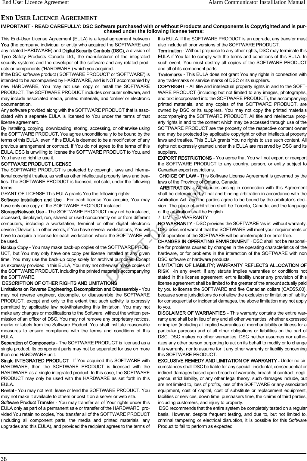
![FCC Compliance StatementCAUTION: Changes or modifications not expressly approved by the Digital Security Controls could voidyour authority to use this equipment.This equipment has been tested and found to comply with the limits for a Class B digital device, pursuant to Part 15 of the FCC Rules.These limits are designed to provide reasonable protection against harmful interference in a residential installation. This equipmentgenerates, uses and can radiate radio frequency energy and, if not installed and used in accordance with the instructions, may causeharmful interference to radio communications. However, there is no guarantee that interference will not occur in a particular installa-tion. If this equipment does cause harmful interference to radio or television reception, which can be determined by turning the equip-ment off and on, the user is encouraged to try to correct the interference by one or more of the following measures:- Re-orient the receiving antenna.- Increase the separation between the equipment and receiver.- Connect the equipment into an outlet on a circuit different from that to which the receiver is connected.- Consult the dealer or an experienced radio/television technician for help.The user may find the following booklet prepared by the FCC useful: ‘How to Identify and Resolve Radio/Television InterferenceProblems’. This booklet is available from the U.S. Government Printing Office, Washington D.C. 20402, Stock # 004-000-00345-4.WARNING: TO SATISFY FCC RF EXPOSURE REQUIREMENTS FOR MOBILE TRANSMITTING DEVICES, A SEPARATION DIS-TANCE OF 20CM OR MORE MUST BE MAINTAINED BETWEEN THE ANTENNA OF THIS DEVICE AND PERSONS DURING DEVICEOPERATION.Industry Canada StatementThe prefix ‘IC:’ in front of the radio certification number signifies only that Industry Canada technical specifications were met.Certification Number IC: 160A-3G255SM This Class B digital apparatus complies with Canadian ICES-003.Cet appareil est conforme avec Industrie Canada exempts de licence standard RSS (s). Le fonctionnement est soumis aux deux condi-tions suivantes: (1) cet appareil ne peut pas provoquer d'interférences et (2) cet appareil doit accepter toute interférence, y compris lesinterferences qui peuvent causer un mauvais fonctionnement de l'appareil.This Class B digital apparatus complies with Canadian ICES-003.Cet appareil numérique de la classe B est conforme à la norme NMB-003 du Canada.DRAFT-02_by_MMFile Name: 29007848R001_Draft_updated_by_MM_DRAFT_02 Changes Log:0711-3:47P - Updated 38 comments from approvals and 2 comments from safety. Emailed: mm2: DN, c/c: HA, FS, HK on 7/11 @ 4:38P.0711-1542 - Pending comments verification from Farhad. FUp.0716-1253 - Updated with Stephan’s comments that apply from pub request 8259, -NA manual.0716-1253 - cw: -to review against all comments from Aun made about pub request 8259 on 07/14 @1545 and- to update with those that are applicable. DONE. FEW QUESTIONS (SPOTS TO WATCH) IDENTIFIEDQ-1: For Aun. Do you want in Table 4, same change in this manual as the one requested on -NA manual on Pg-6 table 5. It was in Description column. The NEW text reads:SG-System IV (SG-DRL3IP) V2.21, and newer instead of original text on line-3. And line-4? Or do you want to keep it as originally left in this manual?Q-2: SOLVED: UA580 placed in the place holder instead of original diagram.Q-3: For Stephan, Original text GPRS was replaced with Cellular (106 changes) as requested by Aun about pub rqst 8259, -NA manual on 07/14 @15:45. Is it OK?Q-4: For Stephan, Original text GSM was replaced with Cellular (19 changes) as requested by Aun about pub rqst 8259, -NA manual on 07/14 @15:45. Is it OK?Q-5: For Aun - Page-5 of this manual: [005] System Toggle Options. Do wee need any updates here about flashes? (Like you asked in -NA manual on 07/14 @15:45). NOTES ARE FOR CONVENIENCE ONLY AND WILL BE REMOVED FROM FINAL VERSION.© 2011 Tyco International Ltd. and its Respective Companies. All Rights Reserved.Toronto, Canada · www.dsc.comTech Support : 1-800-387-3630 (CA, US), 905-760-3000Printed in Canada DRAFT-02_by_MM](https://usermanual.wiki/Tyco-Safety-Canada/113G255SM.users-manual-2/User-Guide-1510735-Page-40.png)