Tyco Safety Canada 113G255SM Dual Alarm Communicator User Manual 29007850R001 Shared Review updated by MM 04
Digital Security Controls Ltd. Dual Alarm Communicator 29007850R001 Shared Review updated by MM 04
Contents
- 1. users manual 1
- 2. users manual 2
users manual 1
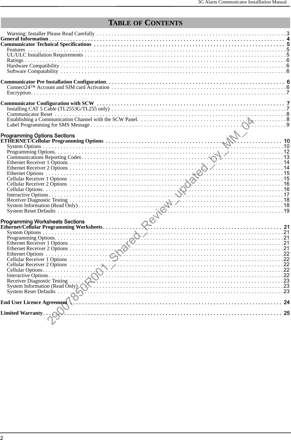
![Keypad Data Display 3G Alarm Communicator Installlation Manual4Domain Name Service (DNS) programming is not permitted in UL/ULC listed systems.KEYPAD DATA DISPLAY•Section-Toggle Options: The number is displayed when Toggle is ON, the number is not displayed when Toggle is OFF. (e.g., Tog-gle Options displays: “[--3--6--]”. Options 3 and 6 are ON, all others are OFF). Pressing keys 1 through 8 will alternately turn theToggle ON and OFF.•HEX/Decimal Data: Values that are provided with two defaults, separated by a / character, use the format: hexadecimal followed bydecimal equivalent (e.g., Default [0BF5/3061]). Hexadecimal numbers are shown, with all leading zeroes, to the full field lengthdefined for the number.ENTERING DATA FROM KEYPADTo enter data at the keypad, press the number key, from the table below, to select the character that you want. Pressing the number keyrepeatedly will scroll through the characters available for that key. Press the [*] key and use [<] [>] keys to scroll to one of the followingselections: (Press [*] to select the Option.)•ASCII Entry. Use this mode to enter ASCII characters from the keypad.•Clear to End. This selection will clear the remainder of the display.•Clear Display.This selection will completely erase all entries on the display.•Change Case. Toggles between upper/lower depending on current selection.NOTE: The “0” on the keypad is used to delete characters.ENTERING ASCII CHARACTERSTo enter American Standard Code for Information Interchange (ASCII) characters at the keypad, perform the following:1. Press [*] and use [<] [>] keys to scroll to “ASCII Entry”.2. Press [*] to select ASCII entry mode.3. Use the [<] [>] keys to scroll to display the ASCII character you want to use and press [*] to accept.4. Press [*] to exit ASCII character entry mode and return to normal entry.NOTE: Authorized access to Connect24 (3G2055/TL2553G) or DLS IV (TL255) is required to modify any Ethernet/Cellular Program-ming Section. Specific panel Sections must be configured for proper operation of the Communicator with the panel. MOUNTING CONSIDERATIONSThe Cellular/Ethernet Communicator is fixed, wall-mounted unit and shall be installed in the location specified in these instructions.The equipment enclosure must be fully assembled and closed, with all the necessary screws/tabs and it must be secured to a wall beforeoperation. Internal wiring must be routed in a manner that prevents:• Excessive strain on wire and on terminal connections,• Interference between power limited and non power limited wiring,• Loosening of terminal connections, or• Damage of conductor insulation.WARNING: NEVER INSTALL THIS EQUIPMENT DURING A LIGHTNING STORM!The Installer must instruct the System user on each of the following items:• This manual shall be used in conjunction with the Alarm controller manual; All the safety instructions specified within that manualshall be observed. (or equivalent)• Do not attempt to service this product. Opening or removing covers may expose the user to dangerous voltages or other risks.• Any servicing shall be referred to trained service personnel only.• Use authorized accessories only with this equipment.Cellular Coverage for Alarm Communicator OperationThe HSPA/3G performance of the 3G2055 and TL2553G Alarm Communicators depends greatly on Cellular network coverage. TheSCW (with internal Alarm Communicator) should not be mounted in the final location without first ensuring that Cellular radio recep-tion is adequate for communication using the HSPA/3G paths. Perfom the “Communicator Placement Test” on page 9. GENERAL INFORMATIONTable 1: Data Entry at KeypadKey Value Key Value Key Value1 1-A-B-C 4 4-J-K-L 7 7-S-T-U2 2-D-E-F 5 5-M-N-O 8 8-V-W-X3 3-G-H-I 6 6-P-Q-R 9 9-Y-Z-029007850R001_Shared_Review_updated_by_MM_04](https://usermanual.wiki/Tyco-Safety-Canada/113G255SM.users-manual-1/User-Guide-1510734-Page-4.png)
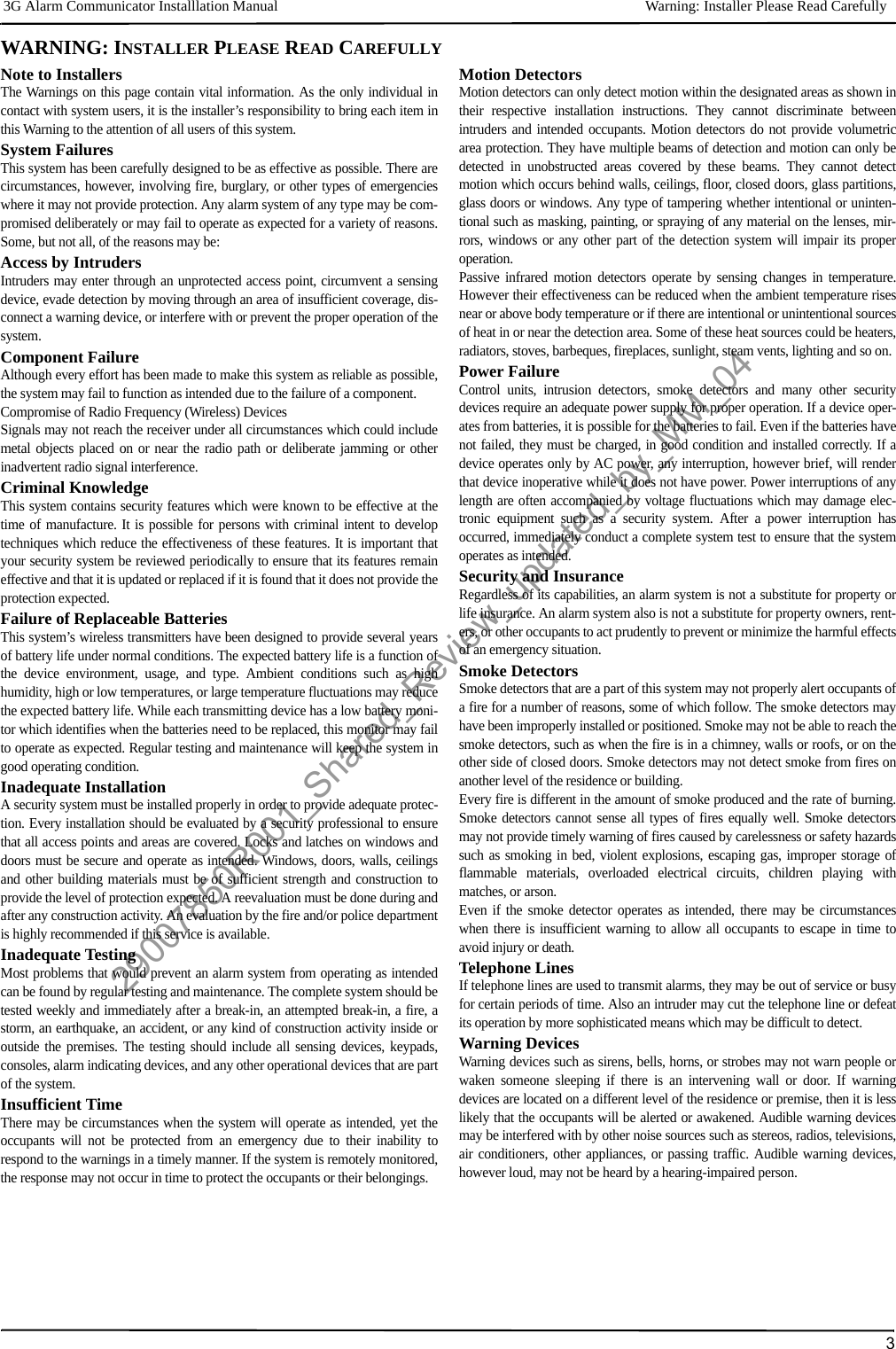
![Inserting/Removing the SIM Card 3G Alarm Communicator Installlation Manual8INSERTING/REMOVING THE SIM CARD1.Remove the front cover of the SCW Control Panel to access SIM card holder.2.Remove power from the SCW and disconnect the backup battery connections.3.On the SIM card holder push gently to slide the cover towards OPEN as indicated by the arrowon SIM holder. This will unlatch the SIM card holder on the side furthest from edge of the Com-municator. See Figure 1.4.Lift up the SIM card holder from the side that is not hinged.NOTE: The SIM card can be damaged by bending or scratching contacts. Use caution when han-dling the SIM card.5.Insert or remove the SIM card, noting the orientation of the notches on the SIM card and the SIMcard holder.6.When inserting a SIM card, insert the card in the proper orientation and gently push the SIM cardholder down and slide the holder as indicated by the arrow on SIM holder, to LOCK.7.Apply AC power to panel, and replace the panel cover.COMMUNICATOR RESETThe Communicator can be reset by cycling the power on the SCW.ESTABLISHING A COMMUNICATION CHANNEL WITH THE SCW PANEL.The Communicator interfaces to the SCW through a keyed 16 pin Ribbon cable. See .Table 6 . Thekey prevents incorrect connection of the ribbon connector to the SCW and Communicator. Thepinout for the Ribbon Interface is provided in the Table below:Establishing a communication channel between the Communicator and the SCW is critical to ensuring the desired operation of the twounits. The following steps must be completed during the on-site installation. Program the following to ensure that the Communicatorand the panel will work together as intended.Initial Programming of Communicator and SCW1. Enter [*][8][Installer Code] [Section Number] for panel programming. Record any values that are modified from their default, in theappropriate Programming Worksheets.NOTE: When programming Toggle Options, the toggle is ON when the number is displayed and OFF when the number is not dis-played. (e.g., [1---5---], Toggle Options 1 and 5 are ON, all others are OFF).2. Panel Section [167] Cellular/Ethernet Interface Communications ‘Wait for ACK’: Program value as: 060 (seconds).3. When the communicator is installed with the SCW panel, 4 telephone number are available to backup one another. You can set upthese 4 telephone numbers to perform in one of two ways: Backup dialling or Alternate dialling.a. Backup dialling: each of the 4 telephone numbers will make 5 dialling attempts in turn, before an FTC trouble is displayed on thekeypad. b. Alternate dialling: each telephone number makes 1 dialling attempt before moving on to the next number, cycling through eachof the 4 numbers for a total of 5 times each. If all 4 numbers fail the 5 attempts,, an FTC trouble is displayed on the keypad.4. Panel Sections [301], [302], [303], and [305] can be configured as Primary communication paths.a. Panel Sections [302], [303], and [305] may also be configured for backup or redundant communications by using Panel Section(s)[383] or [351] - [376]. Refer to the SCW panel Installation Manual for more information.b. If a valid telephone number is programmed, communications will use Public Switched Telephone Network (PSTN). Entering a 4digit hexadecimal value for a telephone number will change the call routing to the Communicator, as determined by the numberprogrammed:DCAAF: Internal (All Receivers). Signals will be routed depending on Section [851] [006] programming.DCBBF: Ethernet Receiver 1 (Primary). (Not available for 3G2055).DCCCF: Ethernet Receiver 2 (Backup). (Not available for 3G2055).DCDDF: Cellular Receiver 1 (Primary). (Not available for TL255).DCEEF: Cellular Receiver 2 (Backup). (Not available for TL255).NOTE: Add a single ‘F’ as a suffix to the 4 digit hex number to populate the unused remainder of the 32 character field.5. Panel Section [350]: If any of the phone numbers have been programmed as DCAA, DCBB, DCCC, DCDD, or DCEE, panel Sec-tion [350] must be set to [04] if SIA format or [03] if Contact ID (CID) format is used by control panel.Table 6: Communicator Ribbon cable to SCWPin # Signal Pin # Signal1 PC-Link TX 2 PC-Link RX3 GND 4 Vref5 Vref 6 GND7 AUD-OUT_N 8 AUD-OUT_P9 AUD-IN_P 10 AUD-IN_N11 GND 12 SI13 GND 14 SO15 GND 16 Wall TamperSIM Card PinoutsDG0009396 Figure 3: SIM Card Pinouts29007850R001_Shared_Review_updated_by_MM_04](https://usermanual.wiki/Tyco-Safety-Canada/113G255SM.users-manual-1/User-Guide-1510734-Page-8.png)
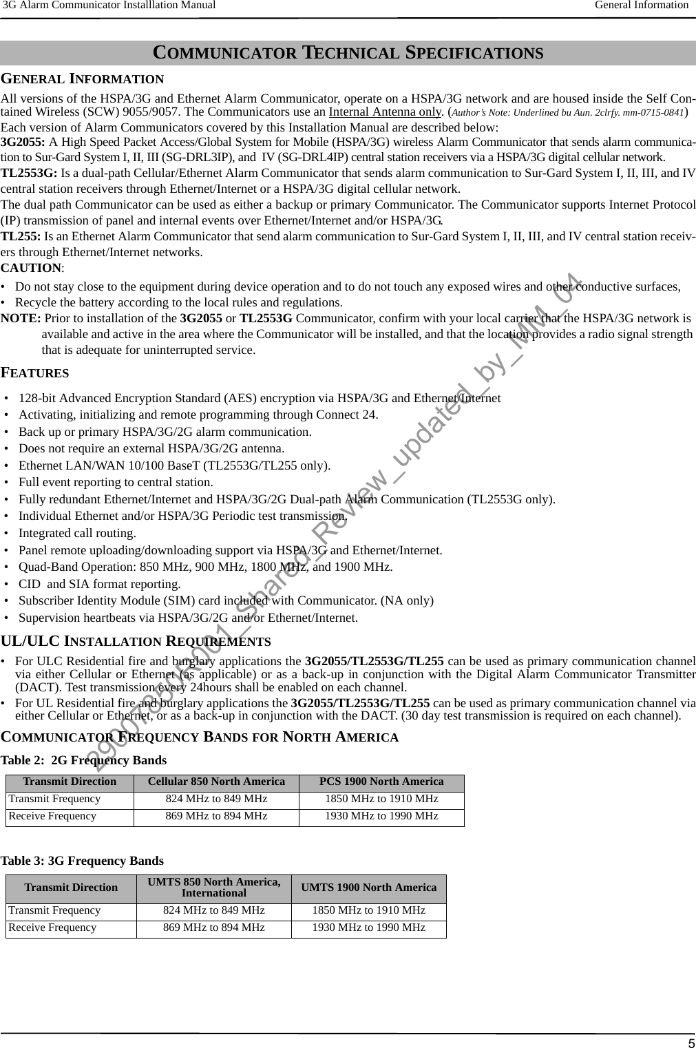
![3G Alarm Communicator Installlation Manual Label Programming for SMS Message96. Panel Section [382]: Toggle Option [5], ‘GS/IP Module Enabled’, must be set to ON.7. Panel Section [401]: Toggle Option [1] must be set to ON in order to perform panel DLS session through Cellular or Ethernet datachanel.NOTE: Keep a record of the SIM card telephone number, it is required by users for SMS Command and Control functions. (The num-ber can be recorded in the Programming Worksheets Section of this document, under Option [996]) Due to the nature of the SIM card activation process with Cellular network carriers, it can take up to 24 hours for SIM card activation to be complete.LABEL PROGRAMMING FOR SMS MESSAGEProgrammable Labels can not be modified in Connect24, use DLS IV for label programming only, if labels need to be modified. Beforeinitiating remote programming, record your network’s Public IP Address and port for incoming DLS IV connections.1. Run the DLS IV software on your computer. DLS IV will connect to the unit, using the Public IP address, and make an Ethernet con-nection. If the Ethernet connection fails, DLS IV will report an error and prompt you to connect using Cellular.NOTE: If required, download the DLS IV software from DSC: http://www.dsc.com/index.php?n=library#self. If you select the Cel-lular connection, DLS will request Connect24 to send an outgoing SMS message to the unit.2. Connect24 will confirm that the account has DLS service and will provide the Public IP address and port number of the DLS serverin an SMS message.3. Type the SMS message text into your cell phone and send it to the Communicator’s Cellular telephone number. Click OK.NOTE: The Cellular phone number can be read from Communicator Section [851][996].4. SMS message will establish a connection to your computer’s DLS IV software (to change programming labels only).5. Create an account for the panel/Communicator, select the Communicator type (e.g., SMS - TL2553G) and enter all relevant infor-mation in SMS section.NOTE: The Cellular telephone number will also be required by the user, to send SMS Interactive messages to their system.6. Program the account information, then click Global Download and choose SMS as the Connection Type. Click OK.7. The download path configured in Programming Section [005] Toggle Option[4] determines the Cellular or Ethernet path to be used.COMMUNICATOR PLACEMENT TEST(3G2055/TL255GS only)1. Using the [<] and [>] keys on the SCW keypad, scroll to the “Signal Strength Menu”.2. Press [*] key to select Signal Strength mode.3. View and record the number of bars showing on the SCW LCD.4. Compare with the number of bars indicated in the “CSQ Levels” column shown in Table 7 .5. If 3 or more bars are shown, the location is GOOD and no further action is required.6. If the location is BAD, move the SCW to various suitable locations until 3 or more bars are obtained.Table 7: Communicator CSQ LevelsSignal Strength CSQ Level Signal Level dBm Installer ActionNo Signal 0 -108.8 Check if Cellular coverage is active in your area.1 Bar 1 to 4 -108d to -103 Location is BAD. Not suitable for Cellular operation.2 Bars 5 to 6 -102 to -99 Location is FAIR. If the average signal strength is CSQ is 5, the system may not communicate events successfully to the Monitoring Station. Installer should consider relocation, if possible3 Bars 7 to 10 -98d to -91 Location is GOOD.4 Bars 11 to 13 -90 to -85 Location is GOOD5 Bars 14 and higher -84 and higher Location is GOOD.29007850R001_Shared_Review_updated_by_MM_04](https://usermanual.wiki/Tyco-Safety-Canada/113G255SM.users-manual-1/User-Guide-1510734-Page-9.png)
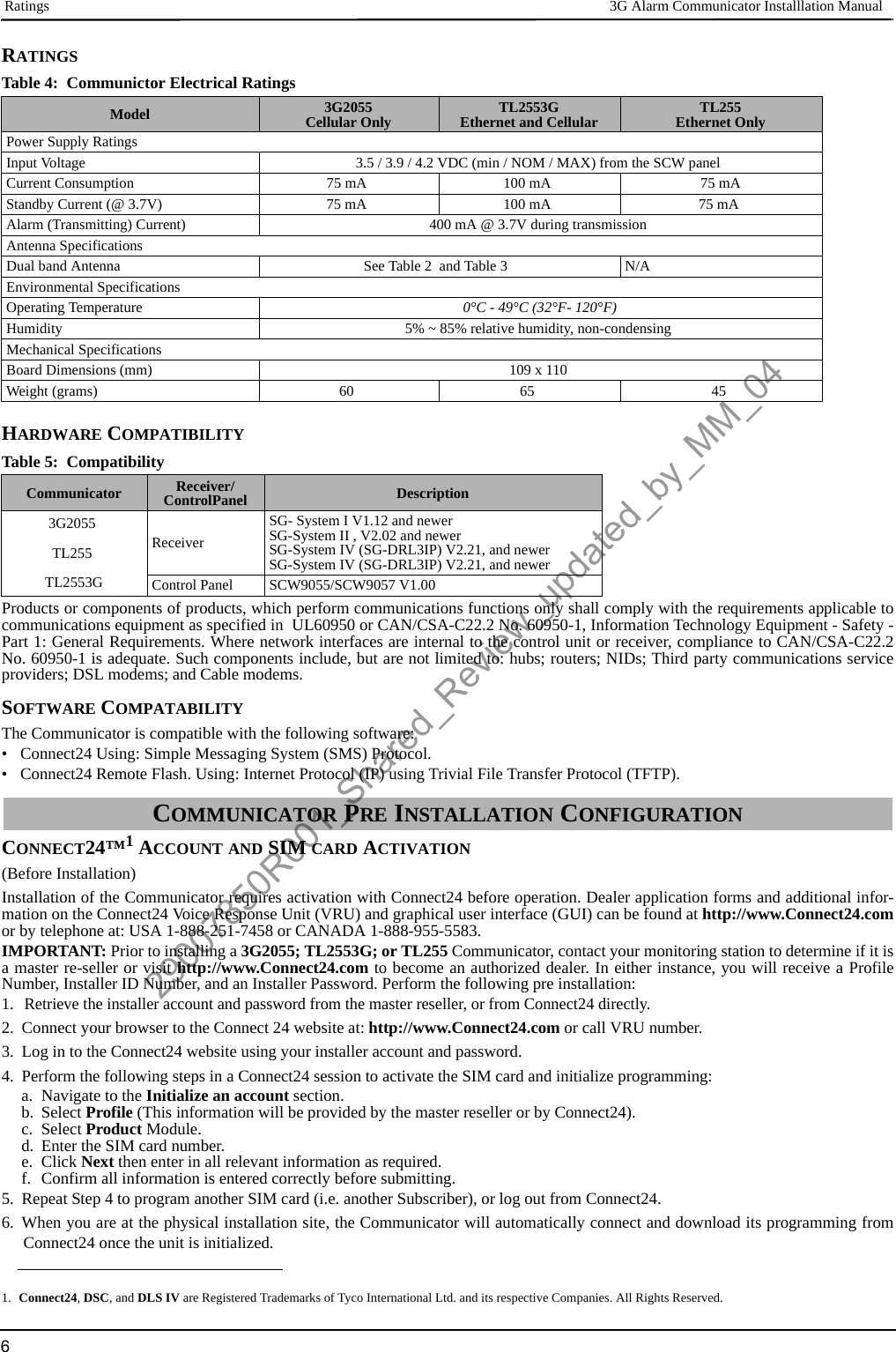
![System Options 3G Alarm Communicator Installlation Manual10The Programming Sections described in this document can be viewed at the SCW LCD. To start programming enter: [*][8][installercode] [851][# # # ], Where ### is the 3 digit Section number referenced in this section. The Programming Worksheets at the end ofthis document can be used to record the new values when programming changes have been made from the default values. Programming Sections are accessed through Connect24. Installers may review/record programming Options at the panel.NOTE: Ethernet/Cellular Programming Sections accessed through the panel are for display purposes only. Configuration changes must be done using Connect24.SYSTEM OPTIONS[001] Ethernet IP AddressDefault (000.000.000.000)Enter the IP address of the Communicator. Ensure that the IP address is unique to your Communicator on the local network. Format is 4fields, each field is a 3 digit decimal number. Valid range: 000-255. If an IP address is programmed in this Section, the unit will operatewith Static IP (DHCP disabled). Sections [002] and [003] must also be programmed when using Static IP addresses.NOTE: Default for this Section is Dynamic Host Configuration Protocol (DHCP) enabled. When enabled, the DHCP Server will setvalues for: IP Address [001], Subnet Mask [002], and Gateway [003]. Programming an IP address in this Section will disableDHCP (Static IP).[002] Ethernet IP Subnet MaskDefault (255.255.255.000)Enter the Ethernet IP Subnet Mask of the Communicator. Format is 4 fields, each field is 3 digits. Valid range: 000-255.NOTE: If DHCP is enabled, the DHCP Server will assign the subnet mask for this Section and the programmed value will be ignored.[003] Ethernet Gateway IP AddressDefault (000.000.000.000)Enter the Ethernet Gateway IP address of the Communicator. The gateway IP address is required when a router is used on the local net-work to reach the destination IP address specified in Section [001]. Format is 4 fields, each field is a 3 digit decimal number. Validrange: 000-255.NOTE: If DHCP is enabled, the DHCP Server will assign the Gateway IP address for this Section and the programmed value will beignored.[004] Receiver Supervision IntervalDefault (0087/135)When receiver supervision is enabled (ON) in Section [005] Toggle Option [3], the unit sends heartbeats to Ethernet Receiver 1 or Cel-lular Receiver 1 to test the communications path. Use this Section to set the interval time (in seconds) when heartbeats will be sent tothe receivers. Valid range 000A-FFFF seconds. If the programmed value is less than (000A/10) seconds, supervision is disabled.•Receiver Window: This is the supervision timeout that must be configured at the central station receiver.•Recommended Values: This is the recommended heartbeat interval that should be programmed into the Communicator.• For ULC passive systems (not using heartbeat supervision), the Daily test transmission must be enabled over each available commu-nication channel Sections [125] and [225]. When programming with Connect24, the recommended intervals will be programmedautomatically when the required window is selected.ETHERNET/CELLULAR PROGRAMMING OPTIONS29007850R001_Shared_Review_updated_by_MM_04](https://usermanual.wiki/Tyco-Safety-Canada/113G255SM.users-manual-1/User-Guide-1510734-Page-10.png)
![3G Alarm Communicator Installlation Manual System Options11[005] System Toggle Options[1] Ethernet Receiver 1 SupervisedDefault (OFF)(TL255/TL2553G only).ON: Ethernet Receiver 1 will be supervised and heartbeats will be sent to Ethernet Receiver 1 based on the supervision interval pro-grammed in Section [004].OFF: Ethernet Receiver 1 will not be supervised. When disabled, heartbeat 1 is sent to the Ethernet receiver once every hour, regard-less of supervision type (heartbeat 1 or 2). The heartbeat is resent every 5 seconds until ACK. If no event or heartbeat ACK is receivedafter (Receiver Supervision Interval + 75 seconds), Supervisory trouble is indicated.(8 flashes on yellow trouble LED). (Author’s Note:AH>MM: “Wherever we have text like this: “Supervisory trouble is indicated. (8 flashes on yellow trouble LED).” , it is to be replaced with new textTBD> For now this text is just a ‘placeholder’. mm-0715-0855)NOTE: Ethernet Receiver 2 can not be supervised.[2] Cellular Receiver 1 Supervised (Author’s Note: m/n-0707-1627:FB,MM “We might replace need to use words Radio/Wireless instead of across entire docu-ment. mm-0715-1526)Default (OFF)ON: Cellular Receiver 1 will be supervised and heartbeats will be sent to Cellular Receiver 1 based on the supervision interval pro-grammed in Section [004]. If ACK to heartbeat is not received, it is retransmitted every 5 seconds. Failure to ACK 2 consecutive heart-beats will reset the radio.OFF: Cellular Receiver 1 will not be supervised. When disabled, heartbeat is not sent to the receiver. Supervisory trouble is indicated.(8 flashes on yellow trouble LED). (Author’s Note: See mm-0715-0855 above, Pg-11.)NOTE: Cellular Receiver 2 can not be supervised.[3] Supervision TypeDefault (OFF)ON: Heartbeat 1 (Commercial Supervision). This supervision type is suitable for applications where swap detection is required on thesupervisory packet.OFF: Heartbeat 2 (Residential Supervision). This supervision type is suitable for applications where supervision of the communicationpath to the receiver is required. (no swap detection).NOTE: Commercial supervision is more data intensive than residential supervision and should only be used when required to meet the approval for the installation.[4] Wireless PrimaryDefault (OFF - TL255/TL2553G) (ON - 3G2055)ON: Cellular channel is the primary path. Ethernet channel is the secondary path, if it exists.OFF: Ethernet channel is the primary path in a dual Communicator. Cellular channel is the secondary path.[5] Redundant Communications Default (OFF) (TL2553G only)ON: Events will be communicated to Ethernet Receiver 1 and Cellular Receiver 1 at the same time. Events will be communicated toEthernet Receiver 2 and Cellular Receiver 2 at the same time. As long as the event is successfully communicated to 1 of the 2 paths(Ethernet or Cellular) the Communicator will move on to the next event.NOTE: Do not configure Ethernet Receiver 1 and Cellular Receiver 1 to communicate using a common receiver configuration (i.e., identical Receiver IP address and Receiver Remote Port). OFF: Events will be communicated to the receivers individually.Tog-gle should be OFF when guaranteed message delivery to both receivers is required. [6] Remote Firmware UpgradeDefault (ON)ON: The Communicator module firmware can be remotely upgraded using the Ethernet/Cellular paths.OFF: The Communicator module firmware can not be remotely upgraded. Local firmware upgrade is still possible.[7] Alternate Test TransmissionsDefault (OFF).ON: When the periodic test transmission interval occurs, the test transmission will alternate between being sent to the primary and sec-ondary receivers with each test transmission interval.OFF: When the periodic test transmission interval occurs, the test transmission will be sent to the programmed receivers, based on thesettings of the periodic test transmission reporting codes.[8] Cellular Low Signal Trouble.Default (OFF)This option masks the Low Signal trouble from the Cellular trouble event (5 flashes on Yellow Trouble LED).ON: A Cellular Trouble event (5 flashes) is transmitted to receiver when the radio signal level falls below threshold level (average CSQlevel is 5 or less).OFF: A Cellular Trouble event (5 flashes) is not transmitted to receiver when the radio signal level falls below threshold level (averageCSQ level is 5 or less). (Author’s Note: See mm-0715-0855 above, Pg-11.)29007850R001_Shared_Review_updated_by_MM_04](https://usermanual.wiki/Tyco-Safety-Canada/113G255SM.users-manual-1/User-Guide-1510734-Page-11.png)
![Programming Options 3G Alarm Communicator Installlation Manual12[006] System Toggle Options 2[1] Ethernet 1 Receiver Enabled.Default (ON) (OFF for 3G2055).ON: Ethernet Receiver 1 is enabled.OFF: Ethernet Receiver 1 is disabled.[2] Ethernet 2 Receiver Enabled.Default (ON) (OFF for 3G2055).ON: Ethernet Receiver 2 is enabled.OFF: Ethernet Receiver 2 is disabled.[3] Reserved. (OFF).[4] Cellular 1 Receiver Enabled.Default (ON).(OFF for TL255)ON: Cellular Receiver 1 is enabled. OFF: Cellular Receiver 1 is disabled.[5] Cellular 2 Receiver Enabled.Default (ON).(OFF for TL255)ON: Cellular Receiver 2 is enabled.OFF: Cellular Receiver 2 is disabled.[6] Reserved (OFF).[7] DLS Over Cellular.Default (ON).NOTE: Program this toggle as OFF if you want to completely disable DLS from using the Cellular path.ON: DLS is enabled on the Cellular path.OFF: DLS is disabled on the Cellular path.NOTE: If this Toggle is OFF, DLS sessions will occur on the Ethernet path only, regardless of Primary Path set in Section [005] Toggle Option [4]. If it is ON then the Communicator will connect to the Primary path first for DLS and if the session fails, the Second-ary path will be used.[8] Interactive over Cellular.Default (ON).[007] DNS Server IP 1Default (000.000.000.000)Programming this Section is not permitted on a UL/ULC listed system.Enter the IP address for DNS Server 1. Format is 4 fields, each field is a 3 digit decimal. Valid range: 000-255.NOTE: If no value is programmed and DHCP is used, the DHCP Server will configure the address. If an address is programmed and DHCP is used, the address that you program will be used instead of the DHCP address.[008] DNS Server IP 2Programming this Section is not permitted on a UL/ULC listed system.Default (000.000.000.000)Enter the IP address for DNS Server 2. Format is 4 fields, each field is a 3 digit decimal. Valid range: 000-255.NOTE: If no value is programmed and DHCP is used, the DHCP Server will assign this value. If an address is programmed and DHCP is used, the address that you program will be used instead of the DHCP address.PROGRAMMING OPTIONS[010] Installer CodeDefault (CAFE)Program your installer code for this Communicator module. The installer code will be required when programming the Communicatormodule. Valid range: 0000 - FFFF. (Author’s Note: m/n-0707-1627:FB,MM “We need to add option [010]. THIS IS PLACE HOLDER. mm-0715-1621)[011] Installer CodeDefault (CAFE)Program your installer code for this Communicator module. The installer code will be required when programming the Communicatormodule. Valid range: 0000 - FFFF.[012] DLS Incoming PortDefault (0BF6/3062)The DLS Incoming Local Port (listening port) is the port DLS IV will use when connecting to the Communicator. If a router or gatewayis used, it must be programmed with a Transmission Control Protocol (TCP) port forward for this port to the Communicator module IPaddress. Valid range: 0000 - FFFF.[013] DLS Outgoing PortDefault (0BFA/3066)The DLS Outgoing Port is used for outgoing session to DLS IV after an SMS request has been sent to the Communicator. Use this Sec-tion to set the value of the local outgoing port. The value must be changed if the Communicator is located behind a firewall and must beassigned a particular port number, as determined by your network administrator. In most cases, changing the default value or configur-29007850R001_Shared_Review_updated_by_MM_04](https://usermanual.wiki/Tyco-Safety-Canada/113G255SM.users-manual-1/User-Guide-1510734-Page-12.png)
![3G Alarm Communicator Installlation Manual Communications Reporting Codes13ing your firewall with this port is not required. Valid range: 0000-FFFF.NOTE: If Section [006] Toggle Option [7] is ON. DLS will use the Primary path for session. If Section [006] Toggle Option [7] is OFFDLS will use the Ethernet path, if available.[020] Installer CodeDefault (CAFE)Program your installer code for this Communicator module. The installer code will be required when programming the Communicatormodule. Valid range: 0000 - FFFF. (Author’s Note: m/n-0707-1627:FB,MM “We need to add option [010]. THIS IS PLACE HOLDER. mm-0715-1632)[021] Account CodeDefault (FFFFFF)The account code is included when transmitting any events generated by the Communicator. (e.g., Panel Absent Trouble). It is recom-mended that the account code be the same as the control panel account number. Valid range: 000001-FFFFFE. If 4 digit account codesare needed the 2 lowest digits shall be programmed as FF.(e.g., Account 1234 is programmed as:1234FF).NOTE: Programming this Section with all 0 or F will cause a Module Configuration Trouble (yellow LED=12 flashes). (Author’s Note: See mm-0715-0855 above, Pg-11.)[022] Communications FormatDefault (04)Program 03 for Contact ID (CID). Program 04 for SIA. The module can be configured to send Events in SIA or CID format. The SIAcommunication format follows the level 2 specifications of the SIA Digital Communication Standard - October 1997. This format willsend the account code along with its data transmission. The transmission will look similar to the following at the receiver. Example:Nri0 ET001Where: N = New Event; ri0 = Partition/Area identifier; ET = Panel Absent Trouble; 001 = Zone 001.COMMUNICATIONS REPORTING CODES[023] Panel Absent TroubleDefault (FF)Program 00 to disable this event or FF to enable. This event will occur when communications with the panel have been lost for morethan 60 seconds.[024] Panel Absent Trouble RestoreDefault (FF)Program 00 to disable this event or FF to enable. This event will occur when communications with the control panel have resumed.[025] Radio Activation RestoreDefault (FF)Program 00 to disable this event or FF to enable. This event will occur after any successful Connect24 programming session.SYSTEM TEST OPTIONS [026 - 029]Test Transmissions to Primary Receiver, with Backup to Secondary Receiver: Set Ethernet Section [026] to (FF); [027] to (00). Set Cellular Section [028] to (FF); [029] to (00).• If the test transmission fails to the primary receiver it will backup to the secondary receiver.• If the test transmission fails to the secondary receiver an FTC trouble will be generated.Test Transmission Unique to Primary and Secondary Receivers:Set Ethernet Section [026] to (FF); [027] to (FF). Set Cellular Section [028] to (FF); [029] to (FF).• The module will send periodic test transmissions to each receiver independently, with no backups.• If the test transmission fails to any of the programmed receivers, an FTC trouble will be generated.Alternate Test Transmission:Alternate Test Transmission can be enabled or disabled in Section [005] Toggle Option [7].Table 8: Communications Reporting CodesEvent SIA IdentifierSIA Reporting CodeCIDQualifierCID Event CodeCID Reporting CodeCID User/Zone[023] Panel Absent Trouble ET 001 1 3 55 001[024] Panel Absent Trouble Restore ER 001 3 3 55 001[025] Radio Activation Restore RS 001 3 5 52 001[026] Ethernet 1 Test Transmission RP 001 1 6 A3 951[027] Ethernet 2 Test Transmission RP 002 1 6 A3 952[028] Cellular 1 Test Transmission RP 003 1 6 A3 955[029] Cellular 2 Test Transmission RP 004 1 6 A3 956[030] FTC Restore YK 001 3 3 54 00129007850R001_Shared_Review_updated_by_MM_04](https://usermanual.wiki/Tyco-Safety-Canada/113G255SM.users-manual-1/User-Guide-1510734-Page-13.png)
![Ethernet Receiver 1 Options 3G Alarm Communicator Installlation Manual14[026] Ethernet 1 TransmissionDefault (FF)Program 00 to disable this event transmission or FF to enable. See System Test Options (above) for details on settings.[027] Ethernet 2 TransmissionDefault (00)Program 00 to disable this event transmission or FF to enable. See System Test Options (above) for details on settings.[028] Cellular 1 TransmissionDefault (FF)Program 00 to disable this event transmission or FF to enable. See System Test Options (above) for details on settings.[029] Cellular 2 TransmissionDefault (00)Program 00 to disable this event transmission or FF to enable. See System Test Options (above) for details on settings.NOTE: The time interval (in minutes) between periodic tests is programmed in Section [125] (Ethernet) and Section [225] (Cellular).[030] FTC RestoreDefault (FF)Program 00 to disable this event transmission or FF to enable. This event will occur when an FTC Trouble on the system restores.ETHERNET RECEIVER 1 OPTIONS[101] Ethernet Receiver 1 Account CodeDefault (0000000000)The account code is used by the central station to distinguish between transmitters. This account code is used when transmitting heart-beat signals to the central station receiver. Signals received from the Panel will use the control panel account number. Valid range:0000000001-FFFFFFFFFE. Programming all 0 or all F will cause a Module Configuration Trouble (yellow LED=12 flashes).NOTE: If Ethernet Receiver 1 and Cellular Receiver 1 are programmed as the same receiver (IP and port number are identical), Ether-net Receiver 1 account code will be used.[102] Ethernet Receiver 1 DNISDefault (000000)The Dialled Number Information Service (DNIS) is used in addition to the Account Code to identify the Communicator module at thecentral station. Valid range: 000000 - 099999. Value is entered as a leading 0 followed by the 5 digit DNIS. Format is Binary CodedDecimal (BCD).NOTE: Each Ethernet/Cellular receiver must be programmed with a unique DNIS.[103] Ethernet Receiver 1 AddressDefault (127.000.000.001)The default address enables the Communicator to operate in Unattended Mode.Unattended Mode is used when a receiver is not available and the unit is required to perform DLS sessions. Typically used where thecustomer programs the control panel daily due to access control and still wants to receive alarms without buying extra hardware(receiver) or software.NOTE: When a valid IP address has been programmed, Ethernet Receiver 1 is enabled and will communicate events over the Ethernetchannel.Ethernet Receiver 1 and Cellular Receiver 1 may be configured to communicate to the same central station receiver. To configure thedevice to operate using this Common Receiver Mode functionality, program Ethernet Receiver 1 and Cellular Receiver 1, IP addressand port number with identical values.NOTE: When operating in Common Receiver Mode, Ethernet Receiver 1 account code will be used for Ethernet and Cellular.[104] Ethernet Receiver 1 Remote PortDefault (0BF5/3061)This Section determines the remote port of Ethernet receiver 1. Valid range: 0000 - FFFF.[105] Ethernet Receiver 1 Local PortDefault (0BF4/3060)Use this Section to set the value of the local outgoing port. Set the value of this port when your installation is located behind a firewalland must be assigned a particular port number as determined by your central station system administrator. Valid range: 0000 - FFFF.[106] Ethernet Receiver 1 Domain Name[106] Ethernet Receiver 1 Domain NameDefault ( )Enter the Domain Name as 32 ASCII characters.Programming this Section is not permitted on a UL/ULC listed system.ETHERNET RECEIVER 2 OPTIONS[111] Ethernet Receiver 2 Account CodeDefault (0000000000)The account code is used by the central station to distinguish between transmitters. The account code is used when transmitting heart-beat signals to the central station receiver. Signals received from the control panel will use the control panel account number. Validrange: 0000000001- FFFFFFFFFE. Programming all 0 or all F will cause a Module Configuration Trouble (yellow LED=12 flashes).NOTE: If both Ethernet Receiver 2 and Cellular Receiver 2 are the same receiver (IP and port number are identical), Ethernet Receiver2 account will be used for Ethernet and Cellular.29007850R001_Shared_Review_updated_by_MM_04](https://usermanual.wiki/Tyco-Safety-Canada/113G255SM.users-manual-1/User-Guide-1510734-Page-14.png)
![3G Alarm Communicator Installlation Manual Ethernet Options15[112] Ethernet Receiver 2 DNISDefault (000000)The DNIS is used in addition to the account code to identify the Communicator module at the central station. Valid range: 000000 -099999. Value is entered as leading 0 followed by the 5 digit DNIS. Format is BCD.NOTE: Each Ethernet/Cellular receiver must be programmed with a unique DNIS.[113] Ethernet Receiver 2 AddressDefault (000.000.000.000)Programming the Ethernet receiver 2 IP address with 000.000.000.000 will disable Ethernet.Enter the Ethernet receiver 2 IP address. This address will be provided by your central station system administrator. Format is 4 fields,each field is a 3 digit decimal. Valid range: 000-255.NOTE: When a valid IP address has been programmed, Ethernet Receiver 2 is enabled and will communicate events over the Ethernet channel.Ethernet Receiver 2 and Cellular Receiver 2 may be configured to communicate to the same central station receiver.To configure the device to operate using this common receiver mode functionality, program the Ethernet Receiver 2 and CellularReceiver 2, IP address and port number with the same values. When operating in common receiver mode the Ethernet Receiver 2account code will be used for communications over Ethernet and Cellular.NOTE: Do not program Ethernet Receiver 1 and Ethernet Receiver 2 to communicate to same receiver.[114] Ethernet Receiver 2 Remote PortDefault (0BF5/3061)This Section is used to program the port number used by Ethernet Receiver 2. Set the value of this port when your installation is locatedbehind a firewall, and must be assigned a particular port number as determined by your central station system administrator. Validrange: 0000 - FFFF.NOTE: Do not program Ethernet Receiver 1 and Ethernet Receiver 2 Port with the same value.[115] Ethernet Receiver 2 Local PortDefault (0BF9/3065)Use this Section to program the value of the local outgoing port. You can set the value of this port when your installation is locatedbehind a firewall and must be assigned a particular port number as determined by your network administrator. Valid range: 0000 -FFFF. NOTE: Do not program Ethernet Receiver 1 and Ethernet Receiver 2 Port with the same value.[116] Ethernet Receiver 2 Domain NameDefault ( )Programming this Section is not permitted on a UL/ULC listed system.Enter the Domain Name as 32 Character ASCII.ETHERNET OPTIONS[124] Ethernet Test Transmission TimeDefault (9999)Enter a 4 digit number (0000-2359) using the 24-hour clock format (HHMM) to set the test transmission time of day. Valid range: 00 - 23 hours (HH) and 00 - 59 minutes (MM). Programming a value of 9999 will disable the test transmission time.NOTE: The internal date and time will automatically be programmed when the unit communicates with the primary receiver.[125] Ethernet Test Transmission CycleDefault (000000)This value represents the interval between test transmissions, in minutes. Valid range: 000000 - 999999 minutes. Once the unit has sentthe initial periodic test transmission, all future test transmissions will be offset by the programmed number of minutes. See Sections[026] - [029].NOTE: Minimum value is 000005 minutes. Programming an interval that is less than 5 minutes will disable test transmission.CELLULAR RECEIVER 1 OPTIONS[201] Cellular Receiver 1 Account CodeDefault (0000000000)The account code is used by the central station to distinguish between transmitters. This account code is used when transmitting heart-beat signals to the central station receiver. Signals received from the control panel will use the control panel account number. Validrange: 0000000001 - FFFFFFFFFE. Programming all 0 or all F will cause a Module Configuration Trouble (yellow LED = 12 flashes).[202] Cellular Receiver 1 DNISDefault (000000)The DNIS is used in addition to the account code to identify the Communicator module at the central station. Valid range: 000000 -099999. Values are entered as leading 0 followed by the five digit DNIS. Format is BCD.NOTE: Each Ethernet/Cellular receiver must be programmed with a unique DNIS.Table 9: Ethernet Test Transmission IntervalTest Transmission Interval Daily Weekly MonthlyProgrammed Minutes 001440 010080 04320029007850R001_Shared_Review_updated_by_MM_04](https://usermanual.wiki/Tyco-Safety-Canada/113G255SM.users-manual-1/User-Guide-1510734-Page-15.png)
![Cellular Receiver 2 Options 3G Alarm Communicator Installlation Manual16[203] Cellular Receiver 1 AddressDefault (000.000.000.000)Enter the Cellular Receiver 1 IP address. This information will be provided by your central station system administrator. Each 3 digitsegment of the address must be within a valid range of 000-255.NOTE: When a valid IP address has been entered, the Cellular is enabled and will communicate events over the Cellular channel.[204] Cellular Receiver 1 PortDefault (0BF5/3061)This Section determines the port used by Cellular Receiver 1. Change the default value of this port when your installation is locatedbehind a firewall, and must be assigned a particular port number as determined by your central station system administrator. Validrange: 0000 - FFFF.NOTE: Programming this Section with 0000 will disable the receiver.[205] Cellular Receiver 1 APNDefault ( )The Access Point Name (APN) determines the Cellular network that the Communicator will connect to. This information is availablefrom your network carrier. Program this Section as 32 ASCII characters.NOTE: When a SIM card with a custom APN is used, the unit will not have access to the Internet. DLS and remote flash can still bedone if Section [221] is programmed with a valid Public APN.[206] Cellular Receiver 1 Domain NameDefault ( )Programming this Section is not permitted on a UL/ULC listed system.Enter the Domain Name as 32 ASCII characters. This information will be provided by your central station system administrator.CELLULAR RECEIVER 2 OPTIONS[211] Cellular Receiver 2 Account CodeDefault (0000000000)The account code is used by the central station to distinguish between different transmitters. This account code is used when transmit-ting signals to the central station receiver. Signals received on the panel will use the panel account number. Valid range: 0000000001 -FFFFFFFFFE. NOTE: Programming this Section as all 0 or F will cause a Module Configuration Trouble (yellow LED = 12 flashes).[212] Cellular Receiver 2 DNISDefault (000000)The DNIS is used in addition to the Account Code to identify the Communicator module at the central station. Valid range: 000000 -099999. Values are entered as a 0 followed by the 5 digit DNIS value. Format is BCD.NOTE: Each Ethernet/Cellular receiver must be programmed with a unique DNIS.[213] Cellular Receiver 2 AddressDefault (000.000.000.000)Enter the Cellular Receiver 2 IP address. This IP address will be provided by your central station. Format is 4 fields, each field is 3 digitdecimal. Valid range: 000 - 255.NOTE: When a valid address has been entered, Cellular Receiver 2 is enabled and will communicate events over the Cellular path. [214] Cellular Receiver 2 PortDefault (0BF5/3061)This Section defines the port of Cellular Receiver 2. Change the value of this port when your installation is located behind a firewall,and must be assigned a particular port number, as determined by your central station system administrator. Valid range: 0000 - FFFF.NOTE: Do not program Cellular Receiver 1 and Cellular Receiver 2 to communicate to the same receiver.[215] Cellular Receiver 2 APNDefault ( )The APN determines the Cellular network that the Communicator will connect to. This information is available from your network car-rier. Program this Section with up to 32 ASCII characters.NOTE: When a SIM card with a custom APN is used, the unit will not have access to the internet. DLS and remote flash can still bedone if Section [221] is programmed with a valid Public APN.[216] Cellular Receiver 2 Domain NameDefault ( )Programming this Section is not permitted on a UL/ULC listed system.Enter the Cellular Receiver 2 Domain Name with up to 32 ASCII characters.CELLULAR OPTIONS[221] Cellular Public Access Point NameDefault ( )When the Communicator is operating on a private APN, use this Section to select a public APN for DLS and Remote Firmware Update.This information is available from your network carrier. The APN identifies the public Cellular network that the Communicator willconnect to.29007850R001_Shared_Review_updated_by_MM_04](https://usermanual.wiki/Tyco-Safety-Canada/113G255SM.users-manual-1/User-Guide-1510734-Page-16.png)
![3G Alarm Communicator Installlation Manual Cellular Options17[222] Cellular Login User NameDefault ( )Some network carriers require you to provide login credentials when connecting to an APN. Program your login User Name in this Sec-tion. Format is up to 32 ASCII characters.NOTE: This Section is not accessible via PC1616/PC1832/PC1864 keypad programming.[223] Cellular Login PasswordDefault ( )Some network carriers require you to provide login credentials when connecting to an APN. Program your login Password in this Sec-tion.Format is up to 32 ASCII characters.[224] Cellular Test Transmission Time of DayDefault (9999)Enter a 4 digit value using the 24-hour clock format (HHMM) to set the test transmission time of day. Valid range: 00-23 for the hours(HH) and 00-59 for the minutes (MM).NOTE: To disable the test transmission time of day enter 9999 or FFFF in this Section.The internal date and time will be automatically programmed by the primary receiver only.[225] Cellular Test Transmission Cycle Default (000000)This value represents the interval in between test transmissions in minutes. Valid range: 000000 - 999999 minutes. Once the unit hassent the initial periodic test transmission, all future test transmissions will be offset by the programmed number of minutes. See Sec-tions [026] - [029].NOTE: Minimum value is 000005 minutes. Programming an interval that is less than 5 minutes will disable test transmission.[226] Cellular Trouble DelayDefault (00)This option is used to program the delay, in minutes, for reporting a Cellular Trouble Delay. Valid entries are 00 - FF. (e.g., for a 10 min-ute Cellular Trouble Delay enter: 0A). There is no reporting delay if value is programmed as 00.[682] Notification Zone 1 - 8 Toggle OptionsThe default for each Notification Zone Toggle is OFF.[683] Notification Zone 9 - 16 Toggle OptionsThe default for each Notification Zone Toggle is OFF.[684] Notification Zone 17 - 24 Toggle OptionsThe default for each Notification Zone Toggle is OFF.[685] Notification Zone 25 - 32 Toggle OptionsThe default for each Notification Zone Toggle is OFF.[686] Notification Zone 33 - 40 Toggle OptionsThe default for each Notification Zone Toggle is OFF.[687] Notification Zone 41 - 48 Toggle OptionsTable 10: Ethernet Test Transmission IntervalTest Transmission Interval Daily Weekly MonthlyProgrammed Minutes 001440 010080 043200Table 11: Notification Zone 1 - 8 ToggleTOGGLE 01 02 03 04 05 06 07 08ZONE 12345678Table 12: Notification Zone 9 - 16 ToggleTOGGLE 01 02 03 04 05 06 07 08ZONE 9 10111213141516Table 13: Notification Zone 17 - 24 ToggleTOGGLE 01 02 03 04 05 06 07 08ZONE 17 18 19 20 21 22 23 24Table 14: Notification Zone 25 - 32 ToggleTOGGLE 01 02 03 04 05 06 07 08ZONE 25 26 27 28 29 30 31 32Table 15: Notification Zone 33 - 40 ToggleTOGGLE 01 02 03 04 05 06 07 08ZONE 33 34 35 36 37 38 39 4029007850R001_Shared_Review_updated_by_MM_04](https://usermanual.wiki/Tyco-Safety-Canada/113G255SM.users-manual-1/User-Guide-1510734-Page-17.png)
![Receiver Diagnostic Testing 3G Alarm Communicator Installlation Manual18The default for each Notification Zone Toggle is OFF.[688] Notification Zone 49 - 56 Toggle OptionsThe default for each Notification Zone Toggle is OFF.[689] Notification Zone 57 - 64 Toggle OptionsThe default for each Notification Zone Toggle is OFF.RECEIVER DIAGNOSTIC TESTING[901] Diagnostic Test Transmission[1] Ethernet 1 (OFF).[2] Ethernet 2 (OFF).[3] Cellular 1 (OFF).[4] Cellular 2 (OFF).[5],[6],[7],[8] Reserved (OFF).This Section may be used by the installer to force the Communicator to send an immediate test transmission to specific receivers, toverify that the communications paths are available. Diagnostic Test Transmission failure will indicate as FTC trouble (Yellow LED = 9flashes). If an FTC error occurs when testing all receivers, select only one receiver and repeat test to isolate the receiver that is not com-municating.SYSTEM INFORMATION (READ ONLY)NOTE: Sections [987] - [998] are provided for information (Read Only). Values in these Sections can not be modified by the Installer.[987] Language VersionThis Section will display the current Language version of the Communicator.[988] DNS 1 IP AddressThis Section will display the IP address of DNS Server 1. This is useful when the unit is configured for DHCP and you need to see theIP address was assigned to the device by the DHCP Server. This value is programmed in Section [007] or assigned by DHCP.[989] DNS 2 IP AddressThis Section will display the IP address of DNS Server 2. This is useful when the unit is configured for DHCP and you need to see theIP address that was assigned to the device by the DHCP Server. This value is programmed in Section [008] or assigned by DHCP.[990] Boot Loader VersionThis Section will display the current Boot Loader version of the Communicator.[991] Firmware VersionThis Section will display the current firmware version of the device. Update worksheets with new version after a flash update is com-pleted.[992] Ethernet IP Address This Section will display the IP address of the Ethernet connection. This value is programmed in Section [001] or assigned by DHCP.[993] Ethernet Gateway Address This Section will display the IP address of the Ethernet Gateway. This value is programmed in Section [003] or assigned by DHCP.[994] Cellular IP AddressThis Section will display the current dynamic IP address assigned by DHCP to the Cellular connection.NOTE: Cellular uses DHCP (Dynamic IP) only. The Cellular IP address is always provided by the Cellular network (i.e., not programmable).[995] SIM NumberThis Section will display the Subscriber Identity Module (SIM) number of the SIM card installed in the Communicator. Format is:Major Industry Identifier (2 digits) Mobile Country Code (2 or 3 digits); Mobile Network Code (2 - 3 digits); Unique Number (10 - 12digits); and Checksum (1 digit). Valid SIM numbers range is: 18 - 21 numbers. This number is printed on SIM and the outside of theCommunicator carton.NOTE: The Checksum digit is omitted on 19 digit SIM Card numbers.[996] Cellular Telephone NumberNOTE: This Section will display the Cellular telephone number of the SIM. This telephone number is required by the Installer for DLSand remote firmware (flash) update. User can access this telephone number by entering [*] [6] < > “Cellular Phone No.” to dis-play the phone number.[997] IMEI NumberTable 16: Notification Zone 41 - 48 ToggleTOGGLE 01 02 03 04 05 06 07 08ZONE 41 42 43 44 45 46 47 48Table 17: Notification Zone 49 - 56 ToggleTOGGLE 01 02 03 04 05 06 07 08ZONE 49 50 51 52 53 54 55 56Table 18: Notification Zone 57 - 64 ToggleTOGGLE 01 02 03 04 05 06 07 08ZONE 57 58 59 60 61 62 63 6429007850R001_Shared_Review_updated_by_MM_04](https://usermanual.wiki/Tyco-Safety-Canada/113G255SM.users-manual-1/User-Guide-1510734-Page-18.png)
![3G Alarm Communicator Installlation Manual System Reset Defaults19This Section will display the unique 15 digit International Mobile Equipment Identity (IMEI) of the radio. Format is: Reporting BodyIdentifier (2 digits), Allocation Number (4 digits); Final Assembly Code (2 digits); Serial Number (6 digits); and a check digit.[998] MAC AddressThis Section will display the unique12 digit, hexadecimal number assigned as the Media Access Control (MAC) address of the device.SYSTEM RESET DEFAULTS[999] Software DefaultDefault (99);The Software default allows the installer to refresh the unit after changes and also return the Communicator to the default state.00: Default Module. All programming Sections in module revert to factory settings. This will erase all existing programming of the unit.55: Reset. The Communicator is reset. This option is equivalent to power cycling the Communicator.29007850R001_Shared_Review_updated_by_MM_04](https://usermanual.wiki/Tyco-Safety-Canada/113G255SM.users-manual-1/User-Guide-1510734-Page-19.png)

![3G Alarm Communicator Installlation Manual System Options21SYSTEM OPTIONS[001] Ethernet IP AddressDefault (000.000.000.000)|____|____|____||____|____|____||____|____|____|____|____|____|[002] Ethernet IP Subnet MaskDefault (255.255.255.000)|____|____|____||____|____|____||____|____|____|____|____|____|[003] Ethernet Gateway IP AddressDefault (000.000.000.000)|____|____|____||____|____|____||____|____|____|____|____|____|[004] Receiver Supervision IntervalDefault (0087/135) Valid range: 0000 - FFFF.|____|____|____|____|[005] System Toggle Options|____| [1] Ethernet Receiver 1 Supervised Default (OFF).|____| [2] Cellular Receiver 1 Supervised Default (OFF).|____| [3] Supervision Type Default (OFF).|____| [4] Primary Communications Path.Default [OFF] TL2553G; [ON]3G2055. |____| [5] Redundant Communications Default (OFF).|____| [6] Remote Firmware Upgrade Default (ON).|____| [7] Alternate Test Transmission Default (OFF).|____| [8] Cellular Low Signal Trouble Default (OFF).[006] System Toggle Options 2|____| [1] Ethernet Receiver 1 Enabled Default (ON).|____| [2] Ethernet Receiver 2 Enabled Default (ON).|____| [4] Cellular Receiver 1 Enabled Default (ON). |____| [5] Cellular Receiver 2 Enabled Default (ON).|____| [7] DLS Over Cellular Default (ON).|____| [8] Interactive Over Cellular Default (ON).[007] DNS Server IP 1Programming not permitted on UL/ULC listed system.Default (000.000.000.000)|____|____|____||____|____|____||____|____|____|____|____|____|[008] DNS Server IP 2Programming not permitted on UL/ULC listed system.Default (000.000.000.000)|____|____|____||____|____|____||____|____|____|____|____|____|PROGRAMMING OPTIONS[011] Installer CodeDefault (CAFE) Valid range: 0000 - FFFF.|____|____|____|____|[012] DLS Incoming PortDefault (0BF6/3062) Valid range: 0000 - FFFF.|____|____|____|____|[013] DLS Outgoing Port Default (0BFA/3066) Valid range: 0000 - FFFF. |____|____|____|____|Program your installer code for this Communicator module. The installer code will be required when programming the Communicator module. Valid range: 0000 - FFFF. (Author’s Note: m/n-0707-1627:FB,MM “We need to add option [010]. THIS IS PLACE HOLDER. mm-0715-1632)Default (FFFFFF) |____|____|____|____|____|____|[022] Communications FormatDefault (04) Program 03 (CID), 04 (SIA).|____|____|[023] Panel Absent TroubleDefault (FF); Program 00 disable or FF enable.|____|____|[024] Panel Absent Trouble RestoreDefault (FF) Program 00 disable or FF enable.|____|____|[025] Radio Activation RestoreDefault (FF) Program 00 disable or FF enable.|____|____|SYSTEM TEST OPTIONS [026 - 029][026] Ethernet 1 TransmissionDefault (FF) Program 00 disable or FF enable.|____|____|[027] Ethernet 2 TransmissionDefault (00) Program 00 disable or FF enable.|____|____|[028] Cellular 1 TransmissionDefault (FF) Program 00 disable or FF enable.|____|____|[029] Cellular 2 TransmissionDefault (00) Program 00 disable or FF enable.|____|____|[030] FTC RestoreDefault (FF) Program 00 disable or FF enable.|____|____|ETHERNET RECEIVER 1 OPTIONS[101] Ethernet Receiver 1 Account CodeDefault (0000000000) Valid range: 0000000001 - FFFFFFFFFE.|____|____|____|____|____|____|____|____|____|____|[102] Ethernet Receiver 1 DNISDefault (000000) Valid range: 000000 - FFFFFF.|____|____|____|____|____|____|[103] Ethernet Receiver 1 AddressDefault (127.000.000.001)|____|____|____||____|____|____||____|____|____|____|____|____|[104] Ethernet Receiver 1 Remote PortDefault (0BF5/3061) Valid range: 0000 - FFFF.|____|____|____|____|[105] Ethernet Receiver 1 Local PortDefault (0BF4/3060)Valid range: 0000 - FFFF.|____|____|____|____|[106] Ethernet Receiver 1 Domain NameDefault ( ) 32 ASCII characters. Programming not permitted on UL/ULC listed system. ________________________________ETHERNET RECEIVER 2 OPTIONS[111] Ethernet Receiver 2 Account CodeDefault (0000000000) Valid range: 0000000001 - FFFFFFFFFE.|____|____|____|____|____|____|____|____|____|____|ETHERNET/CELLULAR PROGRAMMING WORKSHEETS29007850R001_Shared_Review_updated_by_MM_04](https://usermanual.wiki/Tyco-Safety-Canada/113G255SM.users-manual-1/User-Guide-1510734-Page-21.png)
![Ethernet Options 3G Alarm Communicator Installlation Manual22[112] Ethernet Receiver 2 DNISDefault (000000) Valid range: 000000 - 0FFFFF.|____|____|____|____|____|____|[113] Ethernet Receiver 2 AddressDefault (000.000.000.000)|____|____|____||____|____|____||____|____|____|____|____|____|[114] Ethernet Receiver 2 Remote PortDefault (0BF5/3061) Valid range: 0000 - FFFF.|____|____|____|____|[115] Ethernet Receiver 2 Local PortDefault (0BF9/3065) Valid range: 0000 -FFFF.|____|____|____|____|[116] Ethernet Receiver 2 Domain NameDefault ( )Programming not permitted on UL/ULC listed system.____________________________________ETHERNET OPTIONS[124] Ethernet Test Transmission TimeDefault (9999) Valid: 00-23(HH); 00-59(MM)|____|____|____|____|[125] Ethernet Test Transmission CycleDefault (000000)Valid range: 000000 - 999999 minutes.|____|____|____|____|____|____|CELLULAR RECEIVER 1 OPTIONS[201] Cellular Receiver 1 Account CodeDefault (0000000000) Valid range: 0000000001 - FFFFFFFFFE.|____|____|____|____|____|____|____|____|____|____|[202] Cellular Receiver 1 DNISDefault (000000) Valid range: 000000 - 0FFFFF. |____|____|____|____|____|____|[203] Cellular Receiver 1 AddressDefault (000.000.000.000). Valid range: 000-255.|____|____|____||____|____|____||____|____|____|____|____|____|[204] Cellular Receiver 1 PortDefault (0BF5/3061) Valid range: 0000 - FFFF. |____|____|____|____|[205] Cellular Receiver 1 APN Default ( )32 ASCII characters.____________________________________[206] Cellular Receiver 1 Domain NameDefault ( )Programming not permitted on UL/ULC listed system.32 Character ASCII characters.____________________________________CELLULAR RECEIVER 2 OPTIONS[211] Cellular Receiver 2 Account CodeDefault (0000000000)Valid range: 0000000001 - FFFFFFFFFE.|____|____|____|____|____|____|____|____|____|____|[212] Cellular Receiver 2 DNISDefault (000000)Valid range: 000000 - 0FFFFF. |____|____|____|____|____|____|[213] Cellular Receiver 2 AddressDefault (000.000.000.000)Valid segment range: 000-255|____|____|____||____|____|____||____|____|____|____|____|____|[214] Cellular Receiver 2 PortDefault (0BF5/3061) Valid range: 0000 - FFFF.|____|____|____|____|[215] Cellular Receiver 2 APN Default ( ) 32 ASCII characters. ____________________________________[216] Cellular Receiver 2 Domain NameDefault ( )Programming not permitted on UL/ULC listed system. 32 ASCII characters.____________________________________CELLULAR OPTIONS[221] Cellular Public Access Point NameDefault ( ) 32 ASCII characters____________________________________[222] Cellular Login User NameDefault ( ) 32 ASCII characters.____________________________________[223] Cellular Login PasswordDefault ( ) 32 ASCII characters.____________________________________[224] Cellular Test Transmission Time of DayDefault (9999) Valid range: 00 - 23 hrs. (HH) 00 - 59 min. (MM).|____|____|____|____[225] Cellular Test Transmission CycleDefault (000000) Valid range: 000000 - 999999 minutes.|____|____|____|____|____|____|[226] Cellular Trouble DelayDefault (00) Program 00 disable or FF enable.|____|____|INTERACTIVE OPTIONS[651] Interactive Account Code Default (MAC or IMEI) |____|____|____|____|____|____| |____|____|____|____|____|____|[652] Interactive Access CodeDefault (1234)|____|____|____|____|[661] Interactive Baud RateDefault (05)|____|____|[662] Interactive Port Settings Toggle|____| [1] Parity Enabled Default (OFF).|____| [2] Even/Odd Parity Default (OFF).|____| [3]1 or 2 Stop Bits Default (OFF).|____| [4] Flow Control. Default (OFF).29007850R001_Shared_Review_updated_by_MM_04](https://usermanual.wiki/Tyco-Safety-Canada/113G255SM.users-manual-1/User-Guide-1510734-Page-22.png)
![3G Alarm Communicator Installlation Manual Receiver Diagnostic Testing23[681] Notification Event Toggle|____| [1] Alarm/Restore Default (OFF).|____| [2] Tamper/Restore Default (OFF).|____| [3] Opening/Closing Default (OFF).|____| [4] System Maintenance. Default (OFF).|____| [5] System Test Default (OFF).|____| [6] Internal Events Default (OFF).[682] Notification Zone 1 - 8 Toggle Options|____|____|____|____|____|____|____|____| 1 2 3 4 5 6 7 8 [683] Notification Zone 9 - 16 Toggle Options|____|____|____|____|____|____|____|____| 9 10 11 12 13 14 15 16 [684] Notification Zone 17 - 24 Toggle Options|____|____|____|____|____|____|____|____| 17 18 19 20 21 22 23 24 [685] Notification Zone 25 - 32 Toggle Options|____|____|____|____|____|____|____|____| 25 26 27 28 29 30 31 32[686] Notification Zone 33 - 40 Toggle Options|____|____|____|____|____|____|____|____| 33 34 35 36 37 38 39 40 [687] Notification Zone 41 - 48 Toggle Options|____|____|____|____|____|____|____|____| 41 42 43 44 45 46 47 48 [688] Notification Zone 49 - 56 Toggle Options|____|____|____|____|____|____|____|____| 49 50 51 52 53 54 55 56 [689] Notification Zone 57 - 64 Toggle Options|____|____|____|____|____|____|____|____| 57 58 59 60 61 62 63 64RECEIVER DIAGNOSTIC TESTING[901] Diagnostic Test Transmission|___| [1] Ethernet 1 Default (OFF).|___| [2] Ethernet 2 Default (OFF).|___| [3] Cellular 1 Default (OFF).|___| [4] Cellular 2 Default (OFF).SYSTEM INFORMATION (READ ONLY)[988] DNS 1 IP Address|____|____|____||____|____|____||____|____|____|____|____|____|[989] DNS 2 IP Address|____|____|____||____|____|____||____|____|____|____|____|____|[991] Firmware Version |____|____|____|____|____|____|____|____|[992] Ethernet IP Address|____|____|____||____|____|____||____|____|____|____|____|____|[993] Ethernet Gateway Address|____|____|____||____|____|____||____|____|____|____|____|____|[994] Cellular IP Address|____|____|____||____|____|____||____|____|____|____|____|____|[995] SIM Number ____________________________________[996] Cellular Telephone NumberThis number is required for DLS, and Firmware upgrades.____________________________________[997] IMEI Number____________________________________[998] MAC Address |____|____|____|____|____|____| |____|____|____|____|____|____|SYSTEM RESET DEFAULTS[999] Software DefaultDefault (99); Valid entries are 00 or 55|____|____|29007850R001_Shared_Review_updated_by_MM_04](https://usermanual.wiki/Tyco-Safety-Canada/113G255SM.users-manual-1/User-Guide-1510734-Page-23.png)