Tyco Safety Canada 12TR5164 Alarm Transceiver User Manual
Digital Security Controls Ltd. Alarm Transceiver
UserManual.wiki
>
Tyco Safety Canada
>
12TR5164 User Manual
user manual
Navigation menu
Upload a User Manual
Namespaces
Wiki Guide
HTML
PDF
Info
Views
User Manual
Discussion / Help
Navigation
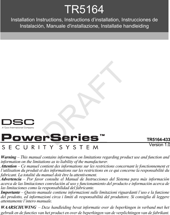

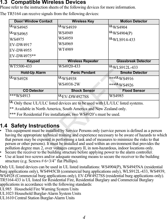
![5Section 2: TR5164 Set Up & WiringThis section describes how to set up and wire the TR5164 module.2.1 Unpack the TR5164Check that the following parts are in the package:• TR5164 PCB • Hardware for mounting the cabinet• TR5164 plastic cabinet2.2 Choose a Mounting Location for the TR5164NOTE: Permanently mount the TR5164 receiver and wireless devices after placement testing each device (Section 5.1, page 11).Find a place that is:• Dry• Within operating temperature range• Central to the proposed placement of all wireless devices• As high as possible• Far from sources of interference, including: electrical noise (computers, televisions and electric motors in appliances and heating and air conditioning units), large metal objects like heating ducts and plumbing which may shield the electro-magnetic waves. For proper unit tamper operation, the surface that the TR5164 is mounted to should be smooth and free of obstructions that block access to the rear of the unit.Ensure that electrical wires do not run over and under the module when it is mounted.When mounting the TR5164 in a basement, place the module as high and as close to the underside of the first floor as possible. The range of the module is reduced if mounted below ground level.2.3 Connect the TR5164 Receiver CAUTION: Remove all power (AC, DC, telephone lines) from the system while connecting modules to the Keybus.KEYBUS TO TR5164Connect the TR5164 to the four-wire Keybus of the control panel according to the diagram.NOTE: Do not use the terminal labeled “GND.”Once the wiring is complete, reconnect power to the security system.Next, enroll and program the wireless devices. See Section 3.2, page 6 for instructions.2.4 TamperThe unit incorporates separate built-in wall and case tampers. The tampers are disabled by default on the NA version (enabled on EU version). Section [804][900] options 3 and 4 enable or disable the tampers.When the TR5164 is properly installed, the wall tamper on the back of the unit should be depressed by the mounting surface. If the unit is removed, the tamper activates. The case tamper activates when the case is opened and restores when the case is closed.NOTE: The built in wall and case tamper must be installed and enabled for UL/ULC Listed Commercial Burglary applications.DRAFT](https://usermanual.wiki/Tyco-Safety-Canada/12TR5164/User-Guide-1778557-Page-7.png)
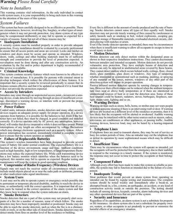
![6Section 3: Receiver ProgrammingEnrollment consists of programming the device’s Electronic Serial Number (ESN) into the TR5164 so that it can be identified when an event is communicated. The ESN is located on the back of each wireless device.NOTE: When programming via hardwired keypad, wireless key programming sections 001-064 and 101-116 only accept 6 digits. To program 8-digit ESNs, only use the last 6 digits.This section describes how to enroll and program:• wireless devices using zones• wireless keys For more information on these devices, read the instruction sheet included with each device.3.1 TR5164 LEDsThe TR5164 features three LEDs to help with the installation of devices and troubleshoot the operation of the unit. In normal operation, the LEDs indicate if the signal received is from an enrolled device.• The green LED flashes when receiving a signal from an enrolled device.• The red LED flashes when receiving a signal from a non-enrolled device.• The yellow LED flashes when interference is detected.Alternatively, when the panel is in placement test mode, the green LED only flashes for the specific serial number entered. All other signals (including signals from valid enrolled devices) flash red.3.2 Enroll the Wireless KeypadDuring initial power up of the alarm panel, a 2-minute window is established for enrolling the wireless keypad (indicated by flashing AC Power and Ready LEDs). If the enrollment window expires, power down the panel then power up again to re-open.To enroll a keypad:1. Power up alarm system.2. Power up keypad. After a few seconds, “Hold [1] and [,] to Enroll Keypad” is displayed on the LCD.3. Press the [,] and [1] keys simultaneously to enroll the keypad. “WFKP Enrollment Successful” is displayed.If the “Failed to Enroll” message is displayed, perform the following:• Retry the enrollment.• Reposition the keypad closer to the control panel.• Verify that the READY and POWER LED indicators are flashing on the panel. If not, disconnect the panel from AC and DC power sources then reconnect.• Check for RF interference. 3.3 Quick Enroll Wireless Devices/Keypads1. Enter [,][8][Installer Code][898]. The following is displayed: “Wireless Enrollment Mode.”2. Activate the device as indicated below. • Keypad: Press the [,] and [1] keys simultaneously.• Wireless key: Press any key to activate.• Detectors (PIR, Smoke, Glass break): Press the Tamper button.• Repeater: Press the Tamper button. Note: Ensure that dip switch 3 on the repeater is in the off position before quick enrolling a repeater.3. The Electronic Serial Number (ESN) is displayed on the keypad. Press [,] to confirm the ESN. If the ESN is incorrect, press [#] then repeat step 2. DRAFT](https://usermanual.wiki/Tyco-Safety-Canada/12TR5164/User-Guide-1778557-Page-8.png)
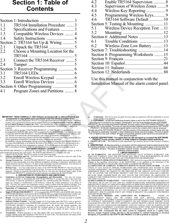
![74. After successful confirmation of the ESN, the system prompts for the zone/slot number.• The next available slot for the device type is displayed. Press [,] to accept or enter the slot number. • To re-enroll a wireless key press simultaneously for approximately 3 seconds.3.4 Manually Enroll Wireless Devices/KeypadsTo manually enroll a 2-way wireless device:1. Enter [,][8][Installer Code][804].2. Enter the 3-digit zone/slot corresponding to the device type:Wireless sensors, pendants and repeaters [804][001]-[064] (excluding [029]-[032])Wireless Key [804][101]-[116] for wireless key numbers 01- 16Wireless Keypad [804][029]-[032]Hardwired and wireless devices cannot be assigned to the same zone. PC5108 zone expander modules occupy zones in 2 groups of 4 (e.g., zones 9-12 and zones 13-16). None of the zones assigned to a PC5108 module may be used for wireless devices. For more information on zone assignment, consult the system Installation Manual.A wireless key can only be assigned to one partition (partition 1 by default). To assign keys to a different partition, see “[804][183] Wireless Key (1-16) Partition Assignments (Default = 01)” on page 19. Note that 2-way wireless keys (WT4989) can only be assigned to partition 1.3. Enter the device serial number. The entry must be 8 digits. For devices with 6-digit serial numbers, enter 00 first. Serial numbers include hexadecimal digits. To toggle between decimal and hexadecimal values, press [,]. For instructions on programming hexadecimal numbers, see the system Installation Manual. The device is now enrolled on the system.4. Record the serial number and the assigned zone number in the programming worksheets in the back of this manual.5. Continue with steps 3 - 5 until all wireless devices are enrolled. 6. Press [#] to exit.NOTE: Zone and partition programming must be completed for the wireless devices to operate correctly (see Section 4.1, page 8).NOTE: (For non-UL listed installations) For Repeaters and Wireless Keypads, non-alarm zone type 26 is recommended. With this zone type, loss of AC or a Low battery condition are not reported to the central station. The alarm panel does not show a trouble for the zone but will indicate it as open. Select the Force Arm attribute for this zone. Program a zone label to identify the WS4920 or WT5500. E.g., "Rptr 1 Pwr Trbl."NOTE: (For UL listed installations) If AC loss and low battery must be reported to the central station, use a 24-hour zone type. Ensure the Audible attribute is set to Silent. To delete a wireless device:1. At a system keypad, enter [,][8][Installer code].2. Enter programming section [804].3. Enter the 3-digit number corresponding to the zone you want to remove the device from.4. Program the ESN as [00000000]. The device is deleted.5. Press [#] to exit.Once all wireless devices are enrolled, program the system to work with the devices. See 4.1 “Program Zones and Partitions” on page 8 for more information.DRAFT](https://usermanual.wiki/Tyco-Safety-Canada/12TR5164/User-Guide-1778557-Page-9.png)
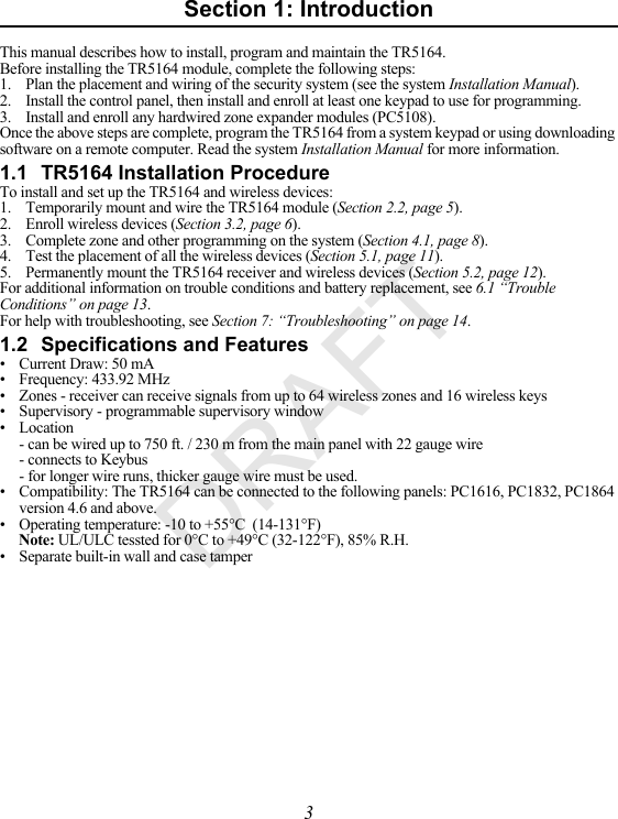
![8Section 4: Other Programming4.1 Program Zones and PartitionsOnce all wireless devices are enrolled, complete zone programming on the system. Although the exact programming required varies depending on which control panel the TR5164 is connected to, ensure that the following programming options are completed correctly for each wireless zone:• Enable zones and/or assign zones to one or more partitions (programming sections [202] to [265]).• Program the definition for each zone (programming sections [001]-[004]).• Enable the wireless zone attribute for each wireless zone (sections [101]-[164]).Refer to the system Installation Manual for more information on the above programming sections.4.2 Enable TR5164 Supervision The control panel can supervise the TR5164 receiver via the Keybus after at least one device has been enrolled on the module (Section 3.2, page 6). To activate module supervision: 1. Enroll the first device(s).2. Exit and then re-enter Installer Programming, [,][8].3. Enter programming section [902]. Wait approximately 1 minute while the system scans for connected modules.4. To exit press [#].The system generates a General System Supervisory trouble if the module is removed from the Keybus. If the TR5164 module must be removed from an existing system, first disable TR5164 supervision.NOTE: Deleting all devices from the TR5164 or defaulting the TR5164 causes a supervisory fault.To disable TR5164 supervision:1. Disconnect the TR5164 from the Keybus.2. Enter [,][8][Installer Code].3. Enter [902]. The control panel clears all supervision and re-scans the system for connected modules. The scan takes approximately one minute.4. To exit press [#].To verify control panel supervision of the TR5164:1. Enter [,][8][Installer Code].2. Enter [903] to display all modules. On a LED 32 zone keypad, light [17] indicates that the TR5164 is present on the system. On LCD keypads, scroll until the TR5164 module name is displayed.3. To exit press [#].If the TR5164 is not detected, check for one of the following problems:• the module is not connected properly to the Keybus• the Keybus wiring run is faulty• the module does not have enough power• no devices have been enrolled on the TR5164DRAFT](https://usermanual.wiki/Tyco-Safety-Canada/12TR5164/User-Guide-1778557-Page-10.png)
![94.3 Enable Supervision of Wireless ZonesEach wireless device (excluding wireless keys) sends a supervisory signal periodically. If the receiver does not receive a signal within the time programmed for the Wireless Supervisory Window, it generates a supervisory fault.NOTE: For wireless supervision to work, enable the wireless zone attribute on all wireless zones (sections [101] to [164], option [8] ON). To program the wireless supervisory window:1. Enter [,][8][Installer Code] to enter Installer Programming.2. Enter [804] to enter the TR5164 Module Programming.3. Enter section [081]. 4. Enter the time period for the supervisory window. The window is programmed in 15 minute increments. The default programming is: • 96 (x15minutes), which is equal to 24 hours for the NA version, or • 8 (x15minutes), which is equal to 2 hours for the EU version. Valid entries are (4) to (96), equal to 1 to 24 hours.5. To exit press [#].NOTE: Supervision must be enabled for RF Delinquency.To disable/enable zone supervision:1. Enter [,][8][Installer Code] to enter Installer Programming.2. Enter [804] to enter the TR5164 Module Programming.3. Enter sections [082]-[089]. Enable or disable supervision for each wireless zone by turning each relevant option on or off. Supervision is enabled by default for all wireless zones.4. To exit press [#]. 4.4 Reporting Openings/Closings by Wireless KeysOpenings, closings and command output activation (e.g., opening a garage door) by individual wireless keys can generate a system report on certain control panels. To enable reporting for wireless key openings/closings: 1. Program a valid access code for each key (using [,][5] access code programming). NOTE: Program these access codes on the system after the TR5164 is connected to the Keybus (Section 2.3, page 5). Access codes 17 – 32 are reserved for wireless keys 01-16 respectively. Refer to the alarm panel Installation Manual for information on access code programming.2. Program an opening and closing reporting code for each key ([339]-[340], [342]-[343]).3. Turn off the Quick Arm option in section [015] option [4] of control panel programming.NOTE: To ensure that an unidentified wireless key cannot disarm the system, turn off section [017], option [1] (in control panel programming).4.5 Program Wireless Key Function ButtonsWireless keys have four or six programmable function buttons. Default functions have been assigned, but other functions may be programmed if desired. NOTE: Wireless keys do not work when the partition they are assigned to is being programmed or bypassed.To program wireless key function buttons:1. At a system keypad, enter [,][8][Installer Code].2. Enter programming section [804].DRAFT](https://usermanual.wiki/Tyco-Safety-Canada/12TR5164/User-Guide-1778557-Page-11.png)
![103. Enter programming section [141] to [156] for wireless keys 1-16.4. For each of the available buttons on the wireless key, enter the 2-digit number corresponding to the selected function. See “Wireless Key Function Key Options” on page 17 for a list of function key options.5. Record all programming choices in the worksheets in the back of the manual.6. To exit press [#].For more information on programming wireless key function buttons, refer to the wireless key installation sheet.4.6 TR5164 Software DefaultReturning the TR5164 programming to factory default settings removes all enrolled devices from the system and resets programming in section [804]. NOTE: Performing this procedure does not reset any other programming sections on the control panel. Likewise, resetting the control panel to factory defaults does not effect TR5164 programming.To reset TR5164 programming to factory default settings:1. Enter [,][8] [Installer Code].2. Enter programming section [996].3. Enter the Installer Code, followed by [996] again. The software for the TR5164 is reset to factory defaults.4. To continue programming the unit, exit and then re-enter Installer Programming by pressing [#] [,][8] [Installer Code].For instructions on resetting the control panel or any other connected module to factory defaults, see the control panel Installation Manual. DRAFT](https://usermanual.wiki/Tyco-Safety-Canada/12TR5164/User-Guide-1778557-Page-12.png)
![11Section 5: Testing & Mounting5.1 Test the Reception of Wireless DevicesTesting the proposed placement of each wireless device before it is mounted is very important. Following these steps tests the signal strength between the TR5164 and the wireless devices. All wireless devices can be tested together (global placement testing) or individually.NOTE: After the wireless devices are enrolled, Installer Programming must be exited and then re-entered at least once before performing a placement test.To perform a global placement test:1. Temporarily place the wireless devices in the preferred mounting locations.2. At a system keypad, enter [,][8][Installer Code].3. Enter section [804], then key in [00]. In this mode, all wireless devices are placement tested at the same time.4. Activate the device(s) as described in the associated installation sheet. The device name and zone number are displayed on the LCD.Read the test results at the keypad:Result LED Keypad LCD Keypad Buzzer/BellGood Light 1 On Steady “Good” 1 Beep/SquawkBad Light 3 On Steady “Bad” 3 Beeps/SquawksActivate the device until three “good” results in a row are achieved. Mount the wireless devices where results are good. Devices indicating a bad result must be moved to another location. The device may only have to be moved a few inches to correct a bad result. Do not mount any device where a “bad” test result is indicated.5. Perform step 4 for each wireless device enrolled on the TR5164. Wait until the placement test of one device is shown/sounded before beginning to test the next device. Continue to test the devices until both the TR5164 and the devices are in good locations. If several wireless devices produce “bad” test results, consider moving the TR5164 to a different location (see Section 2.2, page 5 for tips on finding a location for the TR5164).7. To exit the placement test and return to Installer Programming, press [#] twice.NOTE: To placement test a wireless keypad, press any number key. To placement test a wireless repeater, press the Test button or tamper the device.Testing Individual Devices1. Temporarily place the device in the preferred mounting location.2. At a system keypad, enter [,][8][Installer Code].3. Enter programming section [904] for wireless devices. 4. Enter the 2-digit zone number for the device.5. Activate the device until a result is displayed on the keypad or sounded by the keypad or bell.6. To test another device, press [#] once, then repeat steps 4 - 5. Continue to test the devices until both the TR5164 and the devices are in acceptable locations. If several wireless devices produce “bad” test results, consider moving the TR5164 to a better location (see Section 2.2, page 5 for tips on finding a location for the TR5164).7. To exit the placement test and Installer Programming, press [#] twice.DRAFT](https://usermanual.wiki/Tyco-Safety-Canada/12TR5164/User-Guide-1778557-Page-13.png)
![13Section 6: Additional Notes6.1 Trouble ConditionsThe control panel constantly monitors for possible trouble conditions. If a trouble condition is detected, the keypad beeps and the “Trouble” light turns on. Press [,][2] to display trouble conditions. The following trouble conditions apply to the TR5164 and/or any enrolled devices. •RF Jam Detected (on Power panels v.2.01 and below) - This trouble is generated when the TR5164 detects an RF Jamming condition.•Module Supervision- This trouble is generated if the panel loses communication with any module connected to the Keybus. The event buffer logs a detailed description of the event.•Wireless Device Low Battery - This trouble is generated when a wireless device exhibits a low battery condition. Press [7] one, two, or three times to view which devices are experiencing battery failure. An LED keypad indicates battery failure using zone lights 1 to 8. See Section 6.2, page 13 for more information.•Zone Tamper - This trouble is generated when an enrolled wireless device is removed from its mounting location.•Zone Fault - Each wireless device sends a supervisory signal every 64 minutes (15 minutes for EU). If the receiver does not receive a signal within the time programmed for the Wireless Supervisory Window, a zone fault is generated.•RF Delinquency (EU only) - Each wireless zone sends a supervisory signal every 15 minutes. If the receiver does not receive a signal within 15 minutes, an RF Delinquency trouble is generated for that zone. NOTE: WT5500 keypad and wireless repeater AC and low battery troubles cause the corresponding zone to show as open on the alarm panel.6.2 Wireless Zone Low Battery TransmissionThe battery status of each device is regularly communicated to the alarm panel. If a battery is low, the system logs a Device Low Battery trouble. The system delays reporting the event to the central station for the number of days programmed for Zone Low Battery Transmission Delay in section [377] of the panel. This prevents unnecessary reporting of the event if the user has been instructed on how to replace batteries.Replacing Batteries in Wireless Devices1. Refer to the battery installation instructions on the installation sheet of each device. Be sure to observe correct polarity when installing new batteries. 2. When the new batteries are in place and the tamper is restored, the device sends a battery trouble restoral signal to the TR5164. The battery trouble is cleared and the device should function normally.NOTE: When batteries in one device need replacement, check the batteries in all devices.DRAFT](https://usermanual.wiki/Tyco-Safety-Canada/12TR5164/User-Guide-1778557-Page-15.png)
![15Section 8: Programming WorksheetsTR5164 Wireless ProgrammingUse the following worksheets to record wireless device programming options for future reference.[804] Zone Serial Numbers (for wireless devices, repeaters and keypads)Wireless keypads 1-4 must be enrolled into zones 29-32 respectively. All other wireless devices may be enrolled into any of the remaining 60 zones. Default = 000000Zone Zone Zone[001] [023] [044][002] [024] [045][003] [025] [046][004] [026] [047][005] [027] [048][006] [028] [049][007] Wireless Keypad 1-4 [050][008] [029] [051][009] [030] [052][010] [031] [053][011] [032] [054][012] [033] [055][013] [034] [056][014] [035] [057][015] [036] [058][016] [037] [059][017] [038] [060][018] [039] [061][019] [040] [062][020] [041] [063][021] [042] [064][022] [043]00DRAFT](https://usermanual.wiki/Tyco-Safety-Canada/12TR5164/User-Guide-1778557-Page-17.png)
![16[804][081] Wireless Supervisory Window (Default = 96)The window is programmed in 15 minute increments. The default programming is:• 96 (x15minutes), which is equal to 24 hours (NA), or• 8 (x15minutes), which is equal to 2 hours (EU).Valid entries are (004) to (096), equal to 1 to 24 hours.[804][082]-[089] Zone Transmitter Supervision[082] Zone 1-8 [083] Zones 9-16[084] Zones 17-24[085] Zones 25-32Opt Def. Def. Def. Def.1Zone 1 Zone 9 Zone 17 Zone 252Zone 2 Zone 10 Zone 18 Zone 263Zone 3 Zone 11 Zone 19 Zone 274Zone 4 Zone 12 Zone 20 Zone 285Zone 5 Zone 13 Zone 21 Zone 296Zone 6 Zone 14 Zone 22 Zone 307Zone 7 Zone 15 Zone 23 Zone 318Zone 8 Zone 16 Zone 24 Zone 32[086] Zone 33-40[087] Zones 41-48[088] Zones 49-56[089] Zones 57-64Opt Def. Def. Def. Def.1Zone 33 Zone 41 Zone 49 Zone 572Zone 34 Zone 42 Zone 50 Zone 583Zone 35 Zone 43 Zone 51 Zone 594Zone 36 Zone 44 Zone 52 Zone 605Zone 37 Zone 45 Zone 53 Zone 616Zone 38 Zone 46 Zone 54 Zone 627Zone 39 Zone 47 Zone 55 Zone 638Zone 40 Zone 48 Zone 56 Zone 64 Options DRAFT](https://usermanual.wiki/Tyco-Safety-Canada/12TR5164/User-Guide-1778557-Page-18.png)
![[101] [109][102] [110][103] [111][104] [112][105] [113][106] [114][107] [115][108] [116]17[804][101]-[116] Wireless Key Serial NumbersWireless Key Function Key OptionsEntry Key Description Entry Key Description00 Null Key 17 [,][1] Activate Stay/Away01-02 For Future Use 18 Global Away Arm03 Stay Arm 19 [,][7][3] Command Output #304 Away Arm 20 For Future Use05 [,][9] No-Entry Arm 21 [,][7][4] Command Output #406 [,][4] Chime ON/OFF 22 Global Disarm07 [,][6][code][4] System Test 23-26 For Future Use08-12 For Future Use 27 Disarm (OFF)13 [,][7][1] Command Output #1 28 For Future Use14 [,][7][2] Command Output #2 29 Auxiliary Alarm15 Global Stay Arm 30 Panic Alarm16 [,][0] Quick Exit 31-33 For Future UseNOTE: Wireless keys must have an access code for global arm/global disarm functions. DRAFT](https://usermanual.wiki/Tyco-Safety-Canada/12TR5164/User-Guide-1778557-Page-19.png)
![18[804][141]-[156] Wireless Function Key OptionsFunction 1Default 03Function 2 Default 04Function 3Default 27Function 4 Default 30Function 5 Default 13Function 6 Default 14[141] Key 1[142] Key 2[143] Key 3[144] Key 4[145] Key 5[146] Key 6[147] Key 7[148] Key 8[149] Key 9[150] Key 10[151] Key 11[152] Key 12[153] Key 13[154] Key 14[155] Key 15[156] Key 16NOTE: Functions 5 and 6 are for WT4989 only.DRAFT](https://usermanual.wiki/Tyco-Safety-Canada/12TR5164/User-Guide-1778557-Page-20.png)
![19[804][181]-[182] Enable/Disable 2-Way Wireless Keys 1-16Opt Def. ON OFF Opt Def. ON OFF1Key 1 is 2-way Key 1 is 1-way 9Key 9 is 2-way Key 9 is 1-way2Key 2 is 2-way Key 2 is 1-way 10 Key 10 is 2-way Key 10 is 1-way3Key 3 is 2-way Key 3 is 1-way 11 Key 11 is 2-way Key 11 is 1-way4Key 4 is 2-way Key 4 is 1-way 12 Key 12 is 2-way Key 12 is 1-way5Key 5 is 2-way Key 5 is 1-way 13 Key 13 is 2-way Key 13 is 1-way6Key 6 is 2-way Key 6 is 1-way 14 Key 14 is 2-way Key 14 is 1-way7Key 7 is 2-way Key 7 is 1-way 15 Key 15 is 2-way Key 15 is 1-way8Key 8 is 2-way Key 8 is 1-way 16 Key 16 is 2-way Key 16 is 1-way[804][183] Wireless Key (1-16) Partition Assignments (Default = 01)Key 1 Key 9Key 2 Key 10Key 3 Key 11Key 4 Key 12Key 5 Key 13Key 6 Key 14Key 7 Key 15Key 8 Key 16[804][801] - [864] Custom Door Chime ProgrammingOpt Def ON Def OFF16 Beeps Disabled2“Bing-Bing” sound Disabled3“Ding-Dong” sound Disabled4Alarm Tone Disabled5-8 Future Use (for zones 1-64) DRAFT](https://usermanual.wiki/Tyco-Safety-Canada/12TR5164/User-Guide-1778557-Page-21.png)
![20[804][900] General Wireless OptionsOpt Def ON Def OFF1Future Use2Future Use3Wall Tamper Disabled Wall Tamper Enabled4Case Tamper Disabled Case Tamper Enabled5Wireless Delinquency Disabled Wireless Delinquency Enabled6Future Use7RF Jam Disabled RF Jam Enabled8Future Use[904] Wireless Device Placement TestSee “Testing Individual Devices” on page 11 for details.8.1 Keypad Programming Options[800] Keypad Miscellaneous OptionsOpt Def ON Def OFF1Chime on Openings Enabled Chime on Openings Disabled2Chime on Closings Enabled Chime on Closings Disabled3-8 Future UseEN EN EN EN DRAFTIC statement. This device complies with Industry Canada licence-exempt RSS standard(s). Operation is subject to the following two conditions: (1) this device may not cause interference, and (2) this device must accept any interference, including interference that may cause undesired operation of the device. Le présent appareil est conforme aux CNR d'Industrie Canada applicables aux appareils radio exempts de licence. L'exploitation est autorisée aux deux conditions suivantes : (1) l'appareil ne doit pas produire de brouillage, et (2) l'utilisateur de l'appareil doit accepter tout brouillage radioélectrique subi, même si le brouillage est susceptible d'en compromettre le fonctionnement.](https://usermanual.wiki/Tyco-Safety-Canada/12TR5164/User-Guide-1778557-Page-22.png)
![21FCC Compliance StatementCAUTION: Changes or modifications not expressly approved by Digital Security Controls could void your authority to use this equipment.This equipment generates and uses radio frequency energy and if not installed and used properly, in strict accordance with the manufacturer’s instructions, may cause interference to radio and television reception. It has been type tested and found to comply with the limits for Class B device in accordance with the specifications in Subpart “B” of Part 15 of FCC Rules, which are designed to provide reasonable protection against such interference in any residential installation. However, there is no guarantee that interference will not occur in a particular installation. If this equipment does cause interference to television or radio reception, which can be determined by turning the equipment off and on, the user is encouraged to try to correct the interference by one or more of the following measures:•Re-orient the receiving antenna•Relocate the alarm control with respect to the receiver•Move the alarm control away from the receiver•Connect the alarm control into a different outlet so the alarm control & receiver are on different circuits.+HUHE\ '6& GHFODUHV WKDW WKLV GHYLFH LV LQ FRPSOLDQFH ZLWK WKH HVVHQWLDOUHTXLUHPHQWVDQGRWKHUUHOHYDQWSURYLVLRQVRI'LUHFWLYH(&7KH FRPSOHWH 577( 'HFODUDWLRQ RI &RQIRUPLW\ FDQ EH IRXQG DWKWWSZZZGVFFRPOLVWLQJVBLQGH[DVS[&=( '6& MDNR Y¿UREFH SURKODģXMH ŀH WHQWR Y¿UREHN MH Y VRXODGX VH YģHPLUHOHYDQWQ¯PLSRŀDGDYN\VPÝUQLFH(&'$1'6&HUNO¨UHUKHUYHGDWGHQQHNRPSRQHQWHQRYHUKROGHUDOOHYLNWLJHNUDYVDPWDQGUHEHVWHPPHOVHUJLWWLGLUHNWLY(&'87 +LHUELM YHUNODDUW '6& GDW GLW WRHVWHO LQ RYHUHHQVWHPPLQJ LV PHW GH HLVHQ HQEHSDOLQJHQYDQULFKWOLMQ(&),1'6&YDNXXWWDDODLWWHHQW¦\WW¦Y¦QGLUHNWLLYLQ(&ROHQQDLVHWYDDWLPXNVHW)5( 3DU OD SU«VHQWH '6& G«FODUH TXH FH GLVSRVLWLI HVW FRQIRUPH DX[ H[LJHQFHVHVVHQWLHOOHVHWDXWUHVVWLSXODWLRQVSHUWLQHQWHVGHOD'LUHFWLYH(&*(5+LHUGXUFKHUNO¦UW'6&GD¡GLHVHV*HU¦WGHQHUIRUGHUOLFKHQ%HGLQJXQJHQXQG9RUUDXVHW]XQJHQGHU5LFKWOLQLH(&HQWVSULFKW*5(˂˜˞˱ˬ˲˭˞ˮ˹˪˱ˬ˯ˤ'6&ˡˤ˨˻˪ˢ˦˹˱˦˞˲˱˛ˤ˰˲˰˧ˢ˲˛ ˢ˜˪˞˦ ˰˺˩˳˶˪ˤ ˩ˢ ˱˦˯ˬ˲˰˦˻ˡˤ˯˞˭˞˦˱˛˰ˢ˦˯˧˞˦˩ˢ˹˨ˢ˯˱˦˯˙˨˨ˢ˯˰˴ˢ˱˦˧˚˯˞˪˞˳ˬˮ˚˯˱ˤ˯ˍˡˤˠ˜˞˯(&,7$ &RQ OD SUHVHQWH OD 'LJLWDO 6HFXULW\ &RQWUROV GLFKLDUD FKH TXHVWR SURGRWWR ªFRQIRUPH DL UHTXLVLWL HVVHQ]LDOL HG DOWUH GLVSRVL]LRQL ULOHYDQWL UHODWLYH DOOD 'LUHWWLYD&(125'6&HUNO¨UHUDWGHQQHHQKHWHQHULVDPVYDUPHGGHJUXQQOHJJHQGHNUDYRJºYULJHUHOHYDQWHNUDYLGLUHNWLY()32/'6&RĝZLDGF]DľHXU]ÇG]HQLHMHVWZ]JRGQRĝFL]]DVDGQLF]\PLZ\PDJDQLDPLRUD]SR]RVWDĄ\PLVWRVRZQ\PLSRVWDQRZLHQLDPL'\UHNW\Z\:(3253RU HVWHPHLRD'6& GHFODUDTXHHVWHHTXLSDPHQWRHVW£ HPFRQIRUPLGDGHFRP RV UHTXLVLWRV HVVHQFLDLV H RXWUDV GHWHUPLQD©·HV UHOHYDQWHV GD 'LUHFWLYD(&63$3RU OD SUHVHQWH '6& GHFODUD TXH HVWHHTXLSR HVW£ HQFRQIRUPLGDG FRQ ORVUHTXLVLWRVHVHQFLDOHV\RWURVUHTXLVLWRVUHOHYDQWHVGHOD'LUHFWLYD(&6:('6&EHNU¦IWDUK¦UPHG DWW GHQQD DSSDUDW XSSI\OOHUGHY¦VHQWOLJD NUDYHQ RFKDQGUDUHOHYDQWDEHVW¦PPHOVHUL'LUHNWLYHW(&If necessary, the user should consult the dealer or an experienced radio/television technician for additional suggestions. The user may find the following booklet prepared by the FCC helpful: “How to Identify and Resolve Radio/Television Interference Problems”. This booklet is available from the U.S. Government Printing Office, Washington, D.C. 20402, Stock # 004-000-00345-4.This Class B digital apparatus meets all requirements of the Canadian interference-causing equipment regulations.Cet appareil numérique de la Classe B respecte toutes les exigences de règlement sur le matériel brouilleur du Canada.IC:160A-TRF5164The term ‘IC:’ before the radio certification number only signifies that Industry Canada technical specifications were met.© 2011 Tyco International Ltd. et ses compagnies respectives. Tous droits réservés. © 2011 Tyco International Ltd. y sus respectivas compañías. Todos los derechos reservados. © 2011 Tyco International Ltd. e le società del Gruppo. Tutti i diritti riservati. © 2011 Tyco International Ltd. en de Respective bedrijven. Alle rechten voorbehouden. © 2012 Tyco International Ltd. and its Respective Companies. All Rights Reserved. Toronto, Canada • www.dsc.comTech. Support/Centre d’aide technique/Líneas Tech: 1-800-387-3630 (Can-ada, US), 905-760-3000Printed in Canada / Imprimé au Canada / Impreso en Canadá / Stampato nel Canada / Gedrukt in CanadaDRAFT](https://usermanual.wiki/Tyco-Safety-Canada/12TR5164/User-Guide-1778557-Page-23.png)