Tyco Safety Canada 13HS2HOST9 PowerG Wireless Transceiver User Manual 29008625R001 HSM2HOST v1 0 IM EN FR SP POR
Digital Security Controls Ltd. PowerG Wireless Transceiver 29008625R001 HSM2HOST v1 0 IM EN FR SP POR
UserManual.wiki
>
Tyco Safety Canada
>
13HS2HOST9 User Manual
Users Manual
Navigation menu
Upload a User Manual
Namespaces
Wiki Guide
HTML
PDF
Info
Views
User Manual
Discussion / Help
Navigation
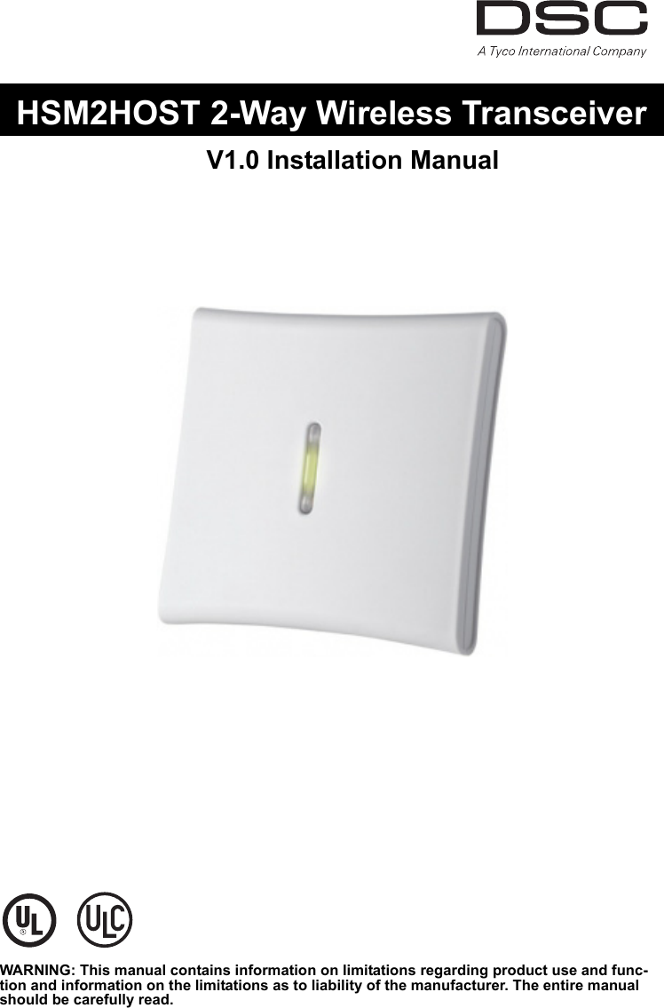
![11. IntroductionThe HSM2HOST two-way wireless transceiver receives signals from wireless zones and wireless keys, and provides information to the alarm controller it is connected to. This manual describes how to install, program and maintain the HSM2HOST.Before installing:1. Plan the placement and wiring of the security system (see system installation manual).2. Install the control panel and optional modules.3. Temporarily mount all wireless devices in the intended location.1.1 Installation Process OverviewTo install and set up the HSM2HOST and wireless devices:1. Temporarily mount and wire the HSM2HOST module (section 2.1.2 on page 2).2. Enroll the HSM2HOST and first Wireless keypad (section 2.1.4 on page 2).3. Check the location for RF interference levels (section Figure: 2.1 on page 2).4. Enroll wireless devices (section 2.4.4 on page 4).5. Complete zone and other programming on the system (section 2.5.1 on page 6).6. Test the placement of all the wireless devices (section 2.5.7 on page 8).7. Permanently mount the HSM2HOST and wireless devices (section 2.3 on page 3).1.2 Controls & IndicatorsStatus LEDsThe LEDs on the front of the HSM2HOST provide feedback regarding the installation, operation and troubleshooting of the unit. The LEDs function as follows:TamperThe HSM2HOST has separate built-in wall and case tampers. The tampers are disabled by default on the NA version (enabled on EU version). Section [804][510] option 3 enables or disables the tampers.The case tamper activates when the case is opened and restores when the case is closed. The wall tamper on the back of the unit is depressed by the mounting surface when prop-erly installed. If the unit is removed, the tamper activates. Ensure the mounting surface is smooth and free of obstructions that block access to the rear of the unit. Electrical wires should not run over or under the module when it is mounted.NOTE: The built-in wall and case tamper must be installed and enabled for UL/ULC ListedCommercial Burglary applications.Red LED OperationModule Power Up: On steady during module power-up sequence then off.Firmware Upgrade: Slow flashing = upgrade in progressRapid flashing = upgrade failed Very rapid flashing = upgrade corrupt, contact distributorTrouble Condition:• No trouble: 1 rapid flash every 10 seconds. If troubles are present, a series of flashes occur every 2 seconds. Each series of flashes indicate troubles as follows:• 1 flash: Module not enrolled• 2 flashes: Loss of contact with module for over 60 seconds• 3 flashes: Corbus low voltage• 7 flashes: Wireless network synchronization• 8 flashes: RF interference (jam condition)Module Confirmation: On solid during module confirmation process.Green LED OperationPlacement Test On steady when location is bad. Off when location is good.](https://usermanual.wiki/Tyco-Safety-Canada/13HS2HOST9/User-Guide-2015346-Page-4.png)
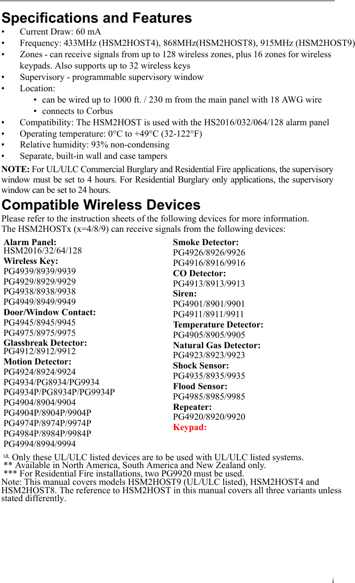
![3Full enrollmentTo enroll the HSM2HOST after initial startup of the alarm panel:1. Enter the following Installer Programming section:[750] (Enroll Module) > [000] (Auto Enroll All Modules)When prompted, activate the HSM2HOST by pressing the tamper button. 2. Press [*]. The module is enrolled into the next available slot for the device.3. Continue the above procedure until all modules are enrolled.Pre-enrollmentPre-enrollment consists of two parts: 1) Prior to installation, program the electronic serial number (ESN) of all modules and select configuration options.2) At the installation site, activate the module.To pre-enroll the HSM2HOST or another module:1. Enter the following Installer Programming section:[750] (Enroll Module) > [001] (Modules)2. Select a module type using the scroll keys or by entering the appropriate hotkey.Table 2-1 Available Modules3. When prompted, key in the serial number found on the back of the device. The mod-ule is enrolled.4. At the installation site, activate each module. The alarm panel does not have to be in Installer Programming mode.2.2 Test HSM2HOST Location for RF InterferenceThe HSM2HOST performs best in locations where RF interference is minimal. To find a suitable mounting location:• With the alarm panel powered up and the HSM2HOST enrolled, observe the status ofthe green LED. If the LED is on, interference levels are high and a new mountinglocation should be found. If the green LED is flashing or off, interference is lowand the location is good.2.3 Permanently MountOnce a suitable location is found, mount the HSM2HOST as follows:1. Pull the Corbus wires through the holes at the back of the cabinet.Hotkey Module Type001 Keypads002 Zone Expander003 Output Module006 HSM2Host008 Audio Verification Module009 Power Supply 1A](https://usermanual.wiki/Tyco-Safety-Canada/13HS2HOST9/User-Guide-2015346-Page-6.png)
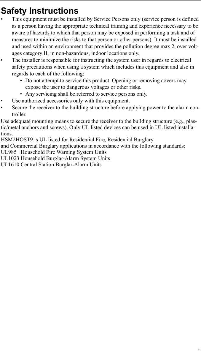
![42. Mount the cabinet securely to the wall using the supplied 3 (three) screws.Figure: 2.2 Mounting the HSM2HOST2.4 Other OptionsThe following actions may be performed on the HSM2HOST, as well as other optional modules. 2.4.1 [751] Delete ModuleTo remove a module from the alarm panel:1. Enter the following Installer Programming section:[751] (Delete Module) > Select module type: see Table 2-1 on page 3.2. When prompted, press [*]. The module is deleted from the system. 2.4.2 [752] Confirm ModuleThis feature is used to confirm that a module is operational and also to help identify a spe-cific module when more that one of the same type is enrolled.To confirm a module:1. Enter the following Installer Programming section:[752] (Confirm Module) > Select module type: see Table 2-1 on page 3.2. When prompted, press [*]. The module serial number is displayed on the keypad and the red LED on the module flashes. 3. Press [#] to exit.2.4.3 [753] Module LabelsTo add a label to a module:1. Enter the following Installer Programming section:[753] (Module Labels) > Select module type: see Table 2-1 on page 3. 2. When prompted, key in a label to identify the module. 3. Press [#] to label another module or [#][#] to exit.2.4.4 [804] Enroll Wireless DevicesOnce the HSM2HOST is installed and enrolled on the alarm panel, wireless devices can be enrolled using one of the following methods:Auto enroll (use to enroll devices during installation):1. Enter the following Installer Programming section:[804] (Wireless Programming) > [000] (Add Wireless Devices) 2. Press [*]. When prompted, activate the device (see device installation sheet). Placeholder ImageNot actual Product](https://usermanual.wiki/Tyco-Safety-Canada/13HS2HOST9/User-Guide-2015346-Page-7.png)
![5The alarm panel determines the type of device being enrolled and presents the appro-priate programming options. Table 2-2 Wireless Device Options3. Use the scroll keys or type in the corresponding number to select an option.4. Scroll through the available selections, key in a number or enter text as appropriate.5. Press [*] to accept and move to the next option.6. Once all options are configured, the system prompts to enroll the next device.Repeat the process described above until all wireless devices are enrolled.NOTE: Configuration options for wireless devices are set using [804]>[201] ModifyDevice.Pre-enroll (use to enroll devices prior to installation)Part 1:1. Enter the following Installer Programming section:[804] (Wireless Programming) > [000] (Add Wireless Devices) 2. Press [*]. When prompted, enter the device ESN. The alarm panel determines the type of device being enrolled and presents the appro-priate programming options (see Table 2-2).3. Use the scroll keys or type in the corresponding number to select an option.4. Scroll through the available selections, key in a number or enter text as appropriate.5. Press [*] to accept and move to the next option.6. Once all options are configured, the system prompts to pre-enroll the next device.Repeat the process described above until all wireless devices are pre-enrolled.Part 2:Once at the installation site, activate the device to complete enrollment. The alarm panel does not have to be in Installer Programming mode.2.4.5 [101]-[104] Delete Wireless DevicesTo delete wireless devices:1. Enter Installer Programming section [804] (Wireless Programming) then select one of the following sub-sections:Table 2-3 Module Label Sub-Sections2. Select a device to delete using the scroll keys or go directly to a specific device by entering a hotkey.Device Type Programming OptionsZone (01) Zone type(02) Partition assignment(03) Zone labelWireless key (01) User labelSiren (01) Partition assignment(02) Siren labelRepeater (01) Repeater LabelSub-Section Description101 Delete wireless zone devices102 Delete Wireless key103 Delete sirens104 Delete repeaters](https://usermanual.wiki/Tyco-Safety-Canada/13HS2HOST9/User-Guide-2015346-Page-8.png)
![63. Press [*] to delete or [#] to exit.2.5 Wireless Device ProgrammingThe following wireless device programming options are available through section [804].2.5.1 [201]-[204] Modify Wireless Device Setup OptionsTo modify wireless device setup options:1. Enter Installer Programming section [804] (Wireless Programming) then navigate to one of the following sub-sections using the scroll keys or by entering a hotkey:Table 2-4 Modify Wireless Device Sub-Sections2. Select a device to modify using the scroll keys or go directly to a specific device by entering a hotkey.3. Press [*] to select the device.4. Press [#] to navigate to the Device Toggles screen then press [*]. The first available option for the selected device is displayed.5. Modify available device programming either by entering the hotkey or using the scroll buttons. 6. Press [#] to move to the next configuration option. Once the last option has been reached, pressing [#] exits the programming section.See section Appendix 1: on page 20 for a complete list of available wireless configu-ration options.2.5.2 [301]-[304] Replace Wireless DevicesUse this option to replace a faulty device enrolled on the system with another device of the same type while maintaining the configuration of the original. The faulty device does not need to be deleted. To replace a wireless device:1. Enter Installer Programming section [804] (Wireless Programming) then select one of the following sub-sections:Table 2-5 Replace Device Sub-Sections2. Press [*] to select a sub-section. A list of available options is displayed.3. Press [*] to select a sub-section. 4. Select a device to replace using the scroll keys or go directly to a specific device by entering a hotkey.5. Press [*]. When prompted, activate the device (full enrollment) or enter the device ID (pre-enrollment). A message is displayed confirming enrollment.Sub-Section Description201 Modify wireless zone devices202 Modify wireless keys203 Modify sirensSub-Section Description301 Replace wireless zone devices302 Replace wireless keys303 Replace sirens304 Replace repeater](https://usermanual.wiki/Tyco-Safety-Canada/13HS2HOST9/User-Guide-2015346-Page-9.png)
![72.5.3 [401]-[410] Wireless Device DefaultsWireless device default parameters used during enrollment can be changed at any time. Once default values are changed, any new devices enrolled inherit the modified default values. The defaults of devices already enrolled are not changed. To modify wireless device defaults:1. Enter [*]>[8]>[804](Wireless Programming) then navigate to one of the following sub-sections using the scroll keys or by entering a hotkey:Table 2-6 Device Type Sub-Sections2. Press [*] to select a sub-section. A list of available options is displayed.3. Navigate the list of options using the scroll keys or by entering a hotkey, then press [*] to select. The first programmable default is displayed.4. Press [*] to select a default or to toggle it on or off.5. Press [#] to move to the next available default. At the last default, pressing [#] returns to the previous list of options.See section Appendix 1: on page 20 for a complete list of available wireless configu-ration options.2.5.4 [501] RF Jam DetectRF jam detection (continuous interfering transmissions on the radio network) can be turned on or off. When on, RF jamming is logged and reported.To configure RF jamming:1. Enter Installer Programming section [804] (Wireless Programming)>[501] (Jam Detect).2. Select one of the following options by scrolling or entering the hotkey:3. Press [*] to accept the selection.4. Press [#] to exit the section.2.5.5 [502] Wireless Supervision WindowThis option is used to program the length of time a wireless device can be absent from the system before a fault is generated. Sub-Section Description401 Contacts402 Motion sensors403 Glassbreak detectors404 Smoke detectors405 CO detectors406 Gas detectors407 Flood detectors408 Temperature detectors409 Wireless keys410 Sirens00 Enabled/Disabled Jamming detection and reporting is enabled/disabled01 UL 20/20-USA Continuous RF jamming for 20 seconds02 EN 30/60-Europe 30 seconds of accumulated jamming within 60 seconds03 Class 6 30/60-British As EN (30/60) but reported only if the jamming duration exceeds 5 minutes](https://usermanual.wiki/Tyco-Safety-Canada/13HS2HOST9/User-Guide-2015346-Page-10.png)
![8NOTE: For EN installations, 1 hour or 2 hours must be selected.To program the Wireless Supervisory Window:1. Enter Installer Programming section [804] (Wireless Programming)>[502] (Wireless Supervisory Window).2. Select one of the following options by scrolling or entering the hotkey:Table 2-7 Wireless Supervisory Window Options3. Press [*] to accept the selection.4. Press [#] to exit the section.2.5.6 [510] Wireless Option 1To program wireless options:1. Enter Installer Programming section [804] (Wireless Programming)>[510] (Missing Report).2. Select one of the following options by scrolling or entering the hotkey:Table 2-8 Wireless Options3. Press [*] to accept the selection.4. Press [#] to exit the section.2.5.7 [600]-[604]Testing Wireless DevicesWireless devices can be tested to verify RF signal status. Test all devices together or by individual device type. The following test modes are available:Table 2-9 Wireless Device Test Modes00 Enabled/Disabled01 After 1 Hour02 After 2 Hour03 After 4 Hour04 After 8 Hour05 After 12 Hour06 After 24 Hour01 RF Delinquency On: the system cannot be armed if a wireless supervisory trouble exists.Off: wireless supervisory troubles do not prevent arming. 02 Wireless Supervi-sory/ RF Jam AlarmOn: If a supervisory or jamming trouble occurs during Away arming, the siren activates and the event is logged and reported.Off: supervisory or RF jam troubles during Away arming do not activate the siren or get logged and reported.03 Module Tamper On: device tampers are logged and reported.Off: device tampers are not logged or reported.04 200-second Fire Supervisory On: fire devices are supervised every 200 seconds. If the device fails to report within this window, a supervision trouble is generated.Off: fire devices follow the supervision window pro-grammed in section 502.600 Test all devices All enrolled wireless devices are tested automatically in the following order: repeaters, sirens, detectors, key-pads. View test results in section [610] Show All Devices. 601 Test wireless zones Test wireless devices individually by zone.](https://usermanual.wiki/Tyco-Safety-Canada/13HS2HOST9/User-Guide-2015346-Page-11.png)
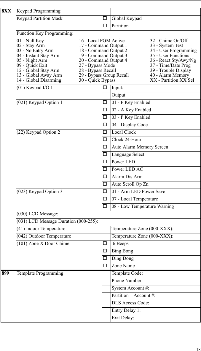
![9Two test results are provided: • 24-hour: Average signal status results received during a 24-hour period.• Now: Signal status results of the current test.The following status indicators may be displayed:Table 2-10 Wireless Device Status Indications[610] Show All DevicesThe results of [600] Test all devices are displayed in this section. This section is only available if a test has been completed.[611] Show RF ProblemsSimilar to section [610] Show All Devices, except that only problematic test results are displayed (i.e., Poor, 1-way, Not Test, Early). 2.5.8 [521]-[552] Programming Wireless KeysTo program wireless key buttons:1. Enter Installer Programming section [804] (Wireless Programming)>[521]-[552] (Wireless Key Buttons).2. Select a wireless key to program (001-032) using the scroll keys or by entering a hot-key.3. Select one of the following options by scrolling or entering the hotkey:Table 2-11 Wireless Key Button Programming Options602 Test wireless keys Test individual wireless keys. Once in this section, press a button on the wireless key to begin the test.603 Test sirens Test each enrolled wireless siren.604 Test repeaters Test each enrolled wireless repeater.Strong Strong signal strengthGood Good signal strengthPoor Poor signal strength1-Way The device is operating in 1-way mode only. The alarm panel cannot configure or control the deviceNot Test Displayed as the Now result if no test was per-formed.None Always displayed as the 24-hour result when testing wireless keys.Early Displayed as the 24-hour result when the panel has been powered up for less than 24 hours.00 Disabled 14 Global Disarm 34 User Programming01 Stay Arm 17 Comm. Output 1 35 User Functions02 Away Arm 18 Comm. Output 2 36 Reactivate Stay/Away/Night03 [*][9] No Entry 19 Comm. Output 3 37 Time/Date Prog.04 Instant Stay Arm 20 Comm. Output 4 39 Trouble Display05 Night Arm 27 Bypass Mode 40 Alarm Memory07 Disarm 28 Bypass Recall 98 Aux. Alarm09 Quick Exit 29 Bypass Group Recall 99 Panic11 Away No Entry 30 Quick Bypass12 Global Stay Arm 32 Chime On/Off](https://usermanual.wiki/Tyco-Safety-Canada/13HS2HOST9/User-Guide-2015346-Page-12.png)
![104. Press [*] to accept the selection.Press [#] to exit the section.2.5.9 [700] Video Verification ProgrammingThe central monitoring station can access video images from motion cameras to verify Burglar, Fire or Panic alarms. Video can be transmitted in one of two ways:• Video on demand: After receiving an alarm, the monitoring station can requestvideo verification. • Video on alarm (default): Video is automatically transmitted to the monitoring sta-tion when an alarm event occurs.The following video verification options can be selected:Table 2-12 Video Verification Programming Options2.5.10 [997] View Module InformationThis section is used to display the model, hardware revision and software version of the HSM2HOST.2.5.11 [999] Reset to Factory DefaultsSelecting this option resets all module programming to factory settings. Panel and other module options are retained.13 Global Away Arm 33 System TestView on Demand • Disable (Video on Alarm mode)• All Arming Modes• Away Arming Only• Stay Arming Only• Stay and Away Arming• Disarm and Away Arming• Disarm and Stay Arming• Disarm Only• View Time Window• View Other AlarmsView Time Window(video on demand)•Always on• Alarm + 5 minutes• Alarm + 15 minutes• Alarm + 1 hourView Other Alarms(non-burglar)•Fire• Duress code•Emergency•Panic](https://usermanual.wiki/Tyco-Safety-Canada/13HS2HOST9/User-Guide-2015346-Page-13.png)
![113. Programming WorksheetsThis section is provided as a reference to available programming options and may also be used to record custom settings. All programming sections below are accessed through Installer Programming ([*][8]).753 Module Labels750 Enroll Module 000 - Auto Enroll001 - Enroll Modules751 Delete Module 001 - Delete Keypads002 - Delete Zone Expander003 - Delete Output Expander006 - Delete HSM2HOST008 - Delete Audio Verification009 - Delete Power Supply752 Confirm Module 001 - Confirm Keypads002 - Confirm Zone Expander003 - Confirm Output Expander006 - Confirm HSM2HOST008 - Confirm Audio Verification009 - Confirm Power Supply001 Keypad Labels (1 x 14 Characters)001: 009:002: 010:003: 011:004: 012:005: 013:006: 014:007: 015:008: 016:002 Zone Expander Labels (1 x 14 Characters)001: 009:002: 010:003: 011:004: 012:005: 013:006: 014:007: 015:008: 016:003 Output Expander Labels (1 x 14 Characters)01:006 HSM2HOST Label (1 x 14 Characters)01:008 HSM2955 Audio Verification Label (1 x 14 Characters)01:](https://usermanual.wiki/Tyco-Safety-Canada/13HS2HOST9/User-Guide-2015346-Page-14.png)
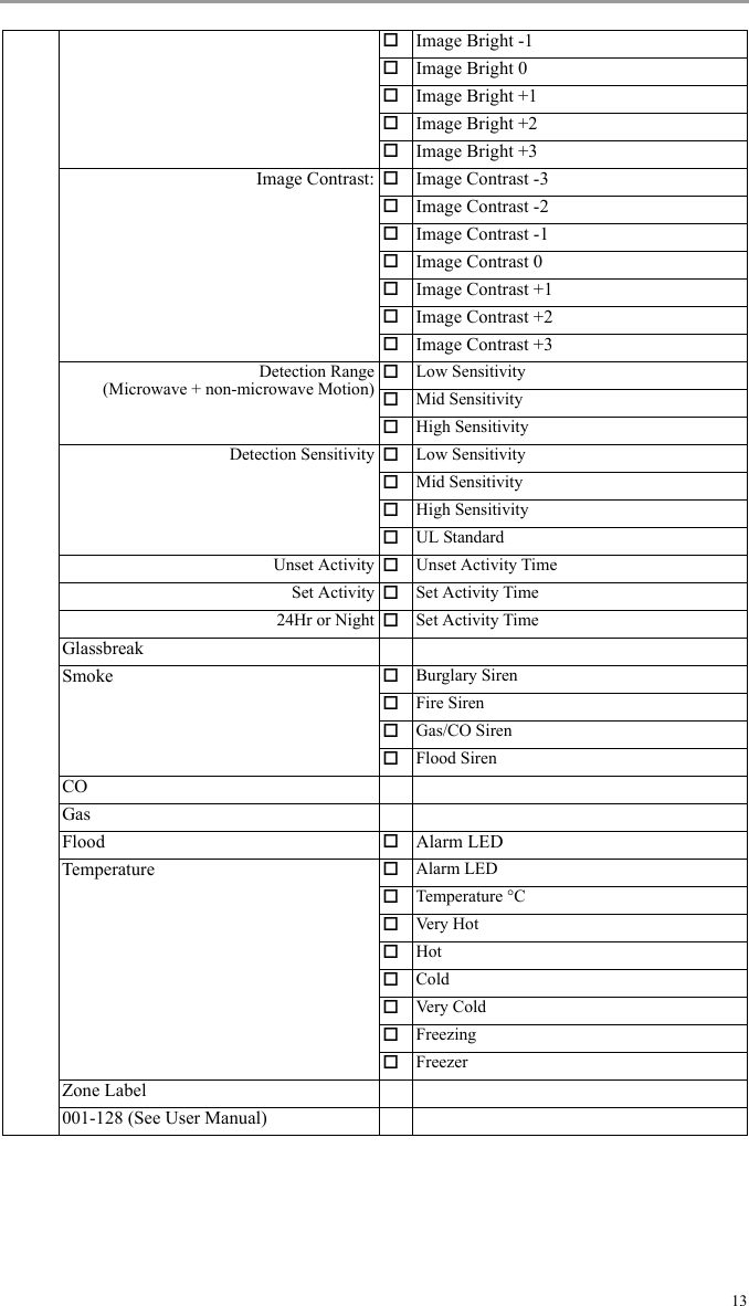
![12[802] Audio Programming (See HSM2955 Installation Manual)[804] Wireless Programming009 HSM2300 Power Supply Label (1 x 14 Characters)01:020 Siren Label (1 x 14 Characters)01:021 Repeater Label (1 x 14 Characters)01:000 Enroll Wireless Device01 - Zone02 - Wireless Key03 - Siren04 - Repeater101 Delete Devices102 Delete Wireless Keys103 Delete Sirens104 Delete Repeaters201 Modify DeviceZone Type:Partition Assignment:Device Toggles (contacts): Alarm LEDReed SwitchZone EOL: DisabledNormally OpenNormally ClosedSingle EOLDevice Toggles (Motion/PIR): Alarm LEDEvent CounterBlack & White/ColorImage ResolutionImage QualityMicrophoneAC PowerDisarm Activity: Not ActiveYes -No De layYes-5 Second DelayYes-15 Second DelayYes-30 Second DelayYes-1 Minute DelayYes-10 Minute DelayYes-60 Minute DelayImage Brightness: Image Bright -3Image Bright -2](https://usermanual.wiki/Tyco-Safety-Canada/13HS2HOST9/User-Guide-2015346-Page-15.png)
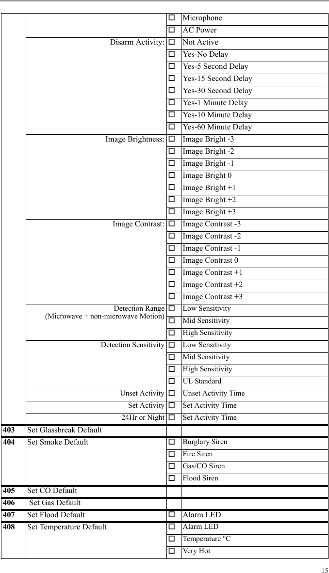
![14202 Wireless KeyAvailable programming options:00- Disabled01- Stay Arm02- Away Arm03- [*][9] No Entry04- Instant Stay Arm05- Night Arm07- Disarm09- Quick Exit11- Away No Entry12- Global Stay Arm13- Global Away Arm14- Global Disarm17- Comm. Output 118- Comm. Output 219- Comm. Output 320- Comm. Output 427- Bypass Mode28- Bypass Recall29- Bypass Group Recall30- Quick Bypass32- Chime On/Off33- System Test34- User Programming35- User Functions36- Reactivate Stay/Away/Night37- Time/Date Prog.39- Trouble Display10- Alarm Memory98- Aux. Alarm99- Panic01: 05: 09: 13: 17: 21: 25: 29:02: 06: 10: 14: 18: 22: 26: 30:03: 07: 11: 15: 19: 23: 27: 31:04: 08: 12: 16: 20: 24: 28: 32:203 Modify SirenDevice Toggles Auto Tmp AlarmAC PowerSmash AlarmStrobe Alarm DisabledTimer LimitedUntil DisarmedExit-Entry Beeps DisabledEnabledDisabled StaySquawk DisabledSounder OnlyStrobe OnlySounder + StrobeSounder Volume LowMediumHigh301 Replace Device 301 - Replace Zone Device302 - Replace Wireless Key303 - Replace Siren304 - Replace Repeater401 Default Set ContactDevice Toggles Alarm LED402 Set Motion Default Alarm LEDEvent CounterBlack & White/ColorImage ResolutionImage Quality](https://usermanual.wiki/Tyco-Safety-Canada/13HS2HOST9/User-Guide-2015346-Page-17.png)
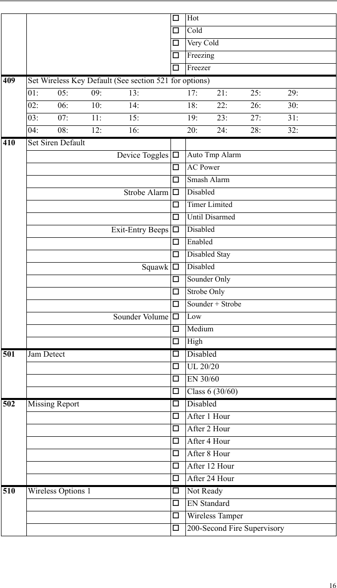
![17521-552Wireless Key ProgrammingAvailable programming options:00- Disabled01- Stay Arm02- Away Arm03- [*][9] No Entry04- Instant Stay Arm05- Night Arm07- Disarm09- Quick Exit11- Away No Entry12- Global Stay Arm13- Global Away Arm14- Global Disarm17- Comm. Output 118- Comm. Output 219- Comm. Output 320- Comm. Output 427- Bypass Mode28- Bypass Recall29- Bypass Group Recall30- Quick Bypass32- Chime On/Off33- System Test34- User Programming35- User Functions36- Reactivate Stay/Away/Night37- Time/Date Prog.39- Trouble Display10- Alarm Memory98- Aux. Alarm99- Panic521: 525: 529: 533: 537: 541: 545: 549:522: 526: 530: 534: 538: 542: 546: 550:523: 527: 531: 535: 539: 543: 547: 551:524: 528: 532: 536: 540: 544: 548: 552:600 Test All Devices601 Test Wireless Zones602 Test Wireless Keys603 Test Sirens604 Test Repeaters610 Show All Devices611 Show RF Problems700 Motion Cameras (Video on Demand)View on Demand DisabledIn All ModesAway OnlyStay OnlyStay and AwayDisarm & AwayDisarm & HomeDisarmed OnlyView Time Window AlwaysAlarm + 5 MinutesAlarm + 15 MinutesAlarm + 1 HourView Other Alarm FireDuressMedicalPanic997 Module Information Model NameSoftware VersionHardware Version999 Default HSM2HOST](https://usermanual.wiki/Tyco-Safety-Canada/13HS2HOST9/User-Guide-2015346-Page-20.png)
![20Appendix 1: Wireless Device Configuration Options[*]>[8]>[804]Wireless Programming>[201]-[204] Device Toggles Section Sub-Section Device Type Option 1 Option 2(201)ModifyWirelessZone Device(001) Contacts(Toggles)(01) Alarm LED(02) Reed Switch(002) Contacts(Zone EOL)(01) Disabled(02) Normally Open(03) Normally Closed(04) Single EOL(003) Motion/PIR (01) Alarm LED(02) Event Counter(03) Black & White/Color(04) Image Resolution(05) Image Quality(06) Microphone(07) AC Power(004) PIR Cameras (01) Disarm Activity (01) Not Active(02) Yes-No Delay(03) Yes + 5 second Delay(04) Yes + 15 second Delay(05) Yes + 30 second Delay(06) Yes + 1 minute Delay(07) Yes + 10 minute Delay(08) Yes + 60 minute Delay(02) Image Brightness (01) Image Bright -3(02) Image Bright -2(03) Image Bright -1(04) Image Bright 0(05) Image Bright +1(06) Image Bright +2(07) Image Bright +3(03) Image Contrast (01) Image Contrast -3(02) Image Contrast -2(03) Image Contrast -1(04) Image Contrast 0(05) Image Contrast +1(06) Image Contrast +2(07) Image Contrast +3(005) Microwave + non-microwave Motion(01) Detection Range (01) Low Sensitivity(02) Mid Sensitivity(03) High Sensitivity(02) Detection Sensitivity (01) Low Sensitivity(02) Mid Sensitivity(03) High Sensitivity(04) UL Standard(03) Unset Activity (01) Unset Activity Time(04) Set Activity (01) Set Activity Time(05) 24Hr or Night (01) Set Act Time(006) Glassbreak(007) Smoke (01) Burglary Siren(02) Fire Siren(03) Gas/CO Siren(04) Flood Siren(008) CO](https://usermanual.wiki/Tyco-Safety-Canada/13HS2HOST9/User-Guide-2015346-Page-23.png)
![IC StatementThis device complies with Industry Canada licence-exempt RSS standard(s). Operation is subject to the following two conditions: (1) this device may not cause interference, and (2) this device must accept any interference, including interference that may cause undesired operation of the device.Le présent appareil est conforme aux CNR d'Industrie Canada applicables aux appareils radio exempts de licence. L'exploitation est autorisée aux deux conditions suivantes : (1) l'appareil ne doit pas produire de brouillage, et (2) l'utilisateur de l'appareil doit accepter tout brouillage radioélectrique subi, même si le brouillage est susceptible d'en compromettre le fonctionnement.FCC Compliance StatementCAUTION: Changes or modifications not expressly approved by Digital Security Controls could void your authority to use this equipment.This equipment generates and uses radio frequency energy and if not installed and used properly, in strict accordance with the manufacturer’s instructions, may cause interference to radio and television reception. It has been type tested and found to comply with the limits for Class B device in accordance with the specifications in Subpart “B” of Part 15 of FCC Rules, which are designed to provide reasonable protection against such interference in any residential installation. However, there is no guarantee that interference will not occur in a particular installation. If this equipment does cause interference to television or radio reception, which can be determined by turning the equipment off and on, the user is encouraged to try to correct the interference by one or more of the following measures:• Re-orient the receiving antenna• Relocate the alarm control with respect to the receiver• Move the alarm control away from the receiver• Connect the alarm control into a different outlet so the alarm control & receiver are on different circuits.If necessary, the user should consult the dealer or an experienced radio/television technician for additional suggestions. The user may find the following booklet prepared by the FCC helpful: “How to Identify and Resolve Radio/Television Interference Problems”. This booklet is available from the U.S. Government Printing Office, Washington, D.C. 20402, Stock # 004-000-00345-4.This Class B digital apparatus meets all requirements of the Canadian interference-causing equipment regulations.Cet appareil numérique de la Classe B respecte toutes les exigences de règlement sur le matériel brouilleur du Canada.IC:160A-HS2HOST9The term ‘IC:’ before the radio certification number only signifies that Industry Canada technical specifications were met.© 2012 Tyco International Ltd. et ses compagnies respectives. Tous droits réservés. © 2012 Tyco International Ltd. y sus respectivas compañías. Todos los derechos reservados. © 2012 Tyco International Ltd. e suas Respectivas Empresas. Todos os Direitos Reservados.© 2012 Tyco International Ltd. and its Respective Companies. All Rights Reserved. Toronto, Canada • www.dsc.comTech. Support/Centre d’aide technique/Líneas Tech: 1-800-387-3630 (Canada, US), 905-760-3000Printed in Canada / Imprimé au Canada / Impreso en Canadá / Impresso no Canadá+HUHE\ '6& GHFODUHV WKDW WKLV GHYLFH LV LQ FRPSOLDQFH ZLWK WKH HVVHQWLDOUHTXLUHPHQWVDQGRWKHUUHOHYDQWSURYLVLRQVRI'LUHFWLYH(&7KH FRPSOHWH 577( 'HFODUDWLRQ RI &RQIRUPLW\ FDQ EH IRXQG DWKWWSZZZGVFFRPOLVWLQJVBLQGH[DVS[&=( '6& MDNR Y¿UREFH SURKODģXMH ŀH WHQWR Y¿UREHN MH Y VRXODGX VH YģHPLUHOHYDQWQ¯PLSRŀDGDYN\VPÝUQLFH(&'$1'6&HUNO¨UHUKHUYHGDWGHQQHNRPSRQHQWHQRYHUKROGHUDOOHYLNWLJHNUDYVDPWDQGUHEHVWHPPHOVHUJLWWLGLUHNWLY(&'87 +LHUELM YHUNODDUW '6& GDW GLW WRHVWHO LQ RYHUHHQVWHPPLQJ LV PHW GH HLVHQ HQEHSDOLQJHQYDQULFKWOLMQ(&),1'6&YDNXXWWDDODLWWHHQW¦\WW¦Y¦QGLUHNWLLYLQ(&ROHQQDLVHWYDDWLPXNVHW)5( 3DU OD SU«VHQWH '6& G«FODUH TXH FH GLVSRVLWLI HVW FRQIRUPH DX[ H[LJHQFHVHVVHQWLHOOHVHWDXWUHVVWLSXODWLRQVSHUWLQHQWHVGHOD'LUHFWLYH(&*(5+LHUGXUFKHUNO¦UW'6&GD¡GLHVHV*HU¦WGHQHUIRUGHUOLFKHQ%HGLQJXQJHQXQG9RUUDXVHW]XQJHQGHU5LFKWOLQLH(&HQWVSULFKW*5(˂˜˞˱ˬ˲ ˭˞ˮ˹˪˱ˬ˯ˤ'6&ˡˤ˨˻˪ˢ˦ ˹˱˦˞˲˱˛ˤ˰˲˰˧ˢ˲˛ ˢ˜˪˞˦˰˺˩˳˶˪ˤ˩ˢ ˱˦˯ˬ˲˰˦˻ˡˤ˯˞˭˞˦˱˛˰ˢ˦˯˧˞˦˩ˢ˹˨ˢ˯˱˦˯˙˨˨ˢ˯˰˴ˢ˱˦˧˚˯˞˪˞˳ˬˮ˚˯˱ˤ˯ˍˡˤˠ˜˞˯(&,7$ &RQ OD SUHVHQWH OD 'LJLWDO 6HFXULW\ &RQWUROV GLFKLDUD FKH TXHVWR SURGRWWR ªFRQIRUPH DL UHTXLVLWL HVVHQ]LDOL HG DOWUH GLVSRVL]LRQL ULOHYDQWL UHODWLYH DOOD 'LUHWWLYD&(125'6&HUNO¨UHUDWGHQQHHQKHWHQHULVDPVYDUPHGGHJUXQQOHJJHQGHNUDYRJºYULJHUHOHYDQWHNUDYLGLUHNWLY()32/'6&RĝZLDGF]DľHXU]ÇG]HQLHMHVWZ]JRGQRĝFL]]DVDGQLF]\PLZ\PDJDQLDPLRUD]SR]RVWDĄ\PLVWRVRZQ\PLSRVWDQRZLHQLDPL'\UHNW\Z\:(3253RUHVWHPHLRD'6&GHFODUDTXHHVWHHTXLSDPHQWRHVW£HPFRQIRUPLGDGHFRP RV UHTXLVLWRV HVVHQFLDLV H RXWUDV GHWHUPLQD©·HV UHOHYDQWHV GD 'LUHFWLYD(&63$3RU ODSUHVHQWH '6&GHFODUD TXHHVWH HTXLSRHVW£ HQFRQIRUPLGDG FRQORVUHTXLVLWRVHVHQFLDOHV\RWURVUHTXLVLWRVUHOHYDQWHVGHOD'LUHFWLYD(&6:('6& EHNU¦IWDUK¦UPHGDWW GHQQDDSSDUDWXSSI\OOHU GHY¦VHQWOLJDNUDYHQ RFKDQGUDUHOHYDQWDEHVW¦PPHOVHUL'LUHNWLYHW(&29008625R001](https://usermanual.wiki/Tyco-Safety-Canada/13HS2HOST9/User-Guide-2015346-Page-28.png)