Tyco Safety Canada 13HS2HOST9 PowerG Wireless Transceiver User Manual 29008625R001 HSM2HOST v1 0 IM EN FR SP POR
Digital Security Controls Ltd. PowerG Wireless Transceiver 29008625R001 HSM2HOST v1 0 IM EN FR SP POR
Users Manual
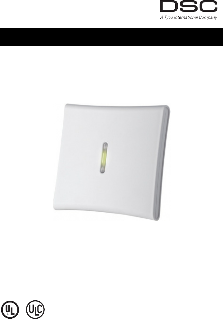
HSM2HOST 2-Way Wireless Transceiver
V1.0 Installation Manual
WARNING: This manual contains information on limitations regarding product use and func-
tion and information on the limitations as to liability of the manufacturer. The entire manual
should be carefully read.

i
Specifications and Features
• Current Draw: 60 mA
• Frequency: 433MHz (HSM2HOST4), 868MHz(HSM2HOST8), 915MHz (HSM2HOST9)
• Zones - can receive signals from up to 128 wireless zones, plus 16 zones for wireless
keypads. Also supports up to 32 wireless keys
• Supervisory - programmable supervisory window
• Location:
• can be wired up to 1000 ft. / 230 m from the main panel with 18 AWG wire
• connects to Corbus
• Compatibility: The HSM2HOST is used with the HS2016/032/064/128 alarm panel
• Operating temperature: 0°C to +49°C (32-122°F)
• Relative humidity: 93% non-condensing
• Separate, built-in wall and case tampers
NOTE: For UL/ULC Commercial Burglary and Residential Fire applications, the supervisory
window must be set to 4 hours. For Residential Burglary only applications, the supervisory
window can be set to 24 hours.
Compatible Wireless Devices
Please refer to the instruction sheets of the following devices for more information.
The HSM2HOSTx (x=4/8/9) can receive signals from the following devices:
Alarm Panel:
HSM2016/32/64/128
Wireless Key:
PG4939/8939/9939
PG4929/8929/9929
PG4938/8938/9938
PG4949/8949/9949
Door/Window Contact:
PG4945/8945/9945
PG4975/8975/9975
Glassbreak Detector:
PG4912/8912/9912
Motion Detector:
PG4924/8924/9924
PG4934/PG8934/PG9934
PG4934P/PG8934P/PG9934P
PG4904/8904/9904
PG4904P/8904P/9904P
PG4974P/8974P/9974P
PG4984P/8984P/9984P
PG4994/8994/9994
Smoke Detector:
PG4926/8926/9926
PG4916/8916/9916
CO Detector:
PG4913/8913/9913
Siren:
PG4901/8901/9901
PG4911/8911/9911
Temperature Detector:
PG4905/8905/9905
Natural Gas Detector:
PG4923/8923/9923
Shock Sensor:
PG4935/8935/9935
Flood Sensor:
PG4985/8985/9985
Repeater:
PG4920/8920/9920
Keypad:
UL Only these UL/ULC listed devices are to be used with UL/ULC listed systems.
** Available in North America, South America and New Zealand only.
*** For Residential Fire installations, two PG9920 must be used.
Note: This manual covers models HSM2HOST9 (UL/ULC listed), HSM2HOST4 and
HSM2HOST8. The reference to HSM2HOST in this manual covers all three variants unless
stated differently.

ii
Safety Instructions
• This equipment must be installed by Service Persons only (service person is defined
as a person having the appropriate technical training and experience necessary to be
aware of hazards to which that person may be exposed in performing a task and of
measures to minimize the risks to that person or other persons). It must be installed
and used within an environment that provides the pollution degree max 2, over volt-
ages category II, in non-hazardous, indoor locations only.
• The installer is responsible for instructing the system user in regards to electrical
safety precautions when using a system which includes this equipment and also in
regards to each of the following:
• Do not attempt to service this product. Opening or removing covers may
expose the user to dangerous voltages or other risks.
• Any servicing shall be referred to service persons only.
• Use authorized accessories only with this equipment.
• Secure the receiver to the building structure before applying power to the alarm con-
troller.
Use adequate mounting means to secure the receiver to the building structure (e.g., plas-
tic/metal anchors and screws). Only UL listed devices can be used in UL listed installa-
tions.
HSM2HOST9 is UL listed for Residential Fire, Residential Burglary
and Commercial Burglary applications in accordance with the following standards:
UL985 Household Fire Warning System Units
UL1023 Household Burglar-Alarm System Units
UL1610 Central Station Burglar-Alarm Units

1
1. Introduction
The HSM2HOST two-way wireless transceiver receives signals from wireless zones and
wireless keys, and provides information to the alarm controller it is connected to. This
manual describes how to install, program and maintain the HSM2HOST.
Before installing:
1. Plan the placement and wiring of the security system (see system installation manual).
2. Install the control panel and optional modules.
3. Temporarily mount all wireless devices in the intended location.
1.1 Installation Process Overview
To install and set up the HSM2HOST and wireless devices:
1. Temporarily mount and wire the HSM2HOST module (section 2.1.2 on page 2).
2. Enroll the HSM2HOST and first Wireless keypad (section 2.1.4 on page 2).
3. Check the location for RF interference levels (section Figure: 2.1 on page 2).
4. Enroll wireless devices (section 2.4.4 on page 4).
5. Complete zone and other programming on the system (section 2.5.1 on page 6).
6. Test the placement of all the wireless devices (section 2.5.7 on page 8).
7. Permanently mount the HSM2HOST and wireless devices (section 2.3 on page 3).
1.2 Controls & Indicators
Status LEDs
The LEDs on the front of the HSM2HOST provide feedback regarding the installation,
operation and troubleshooting of the unit. The LEDs function as follows:
Tamper
The HSM2HOST has separate built-in wall and case tampers. The tampers are disabled by
default on the NA version (enabled on EU version). Section [804][510] option 3 enables
or disables the tampers.
The case tamper activates when the case is opened and restores when the case is closed.
The wall tamper on the back of the unit is depressed by the mounting surface when prop-
erly installed. If the unit is removed, the tamper activates. Ensure the mounting surface is
smooth and free of obstructions that block access to the rear of the unit. Electrical wires
should not run over or under the module when it is mounted.
NOTE: The built-in wall and case tamper must be installed and enabled for UL/ULC Listed
Commercial Burglary applications.
Red LED Operation
Module Power Up: On steady during module power-up sequence then off.
Firmware Upgrade: Slow flashing = upgrade in progress
Rapid flashing = upgrade failed
Very rapid flashing = upgrade corrupt, contact distributor
Trouble Condition:
• No trouble: 1 rapid flash every 10 seconds.
If troubles are present, a series of flashes occur every 2 seconds.
Each series of flashes indicate troubles as follows:
• 1 flash: Module not enrolled
• 2 flashes: Loss of contact with module for over 60 seconds
• 3 flashes: Corbus low voltage
• 7 flashes: Wireless network synchronization
• 8 flashes: RF interference (jam condition)
Module Confirmation: On solid during module confirmation process.
Green LED Operation
Placement Test On steady when location is bad. Off when location is good.
2
2.1 Setup & Wiring
This section describes how to set up and wire the HSM2HOST module.
2.1.1 In the Box
Check that the following parts are in the package:
• HSM2HOST module
• Mounting hardware
• Installation manual
2.1.2 Choose a Mounting Location
NOTE: Permanently mount the HSM2HOST receiver and wireless devices AFTER place-
ment testing each device (section 2.3 on page 3).
Find a place that is
•dry,
• within operating temperature range,
• central to the proposed placement of all wireless devices,
• as high as possible. The range is reduced if mounted below ground level,
• far from sources of interference, including: electrical noise (computers, televisions,
electric motors, appliances, heating and air conditioning units), large metal objects
like heating ducts and plumbing which may shield the electro-magnetic waves,
• smooth and free of obstructions that block access to the rear of the unit.
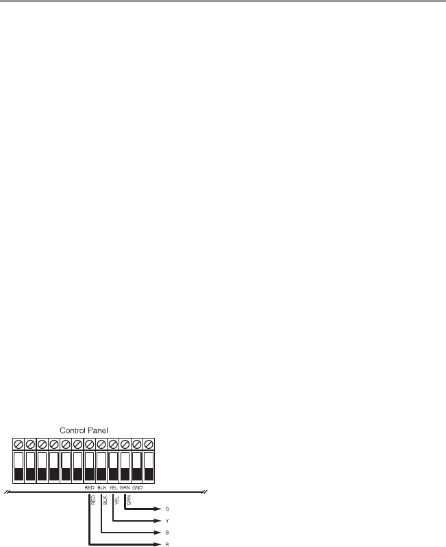
2.1.3 Connect the HSM2HOST
Caution: Remove all power (AC, DC, telephone lines) from the system while connecting mod-
ules to the Corbus.
1. With the alarm panel powered down, connect the HSM2HOST to the four-wire Cor-
bus of the alarm panel according to Figure 1.
2. Once the wiring is complete, power up the security system.
Figure: 2.1 Wiring
2.1.4 Enroll The HSM2HOST
The HSM2HOST can be enrolled in one of three ways:
At initial power-up of the alarm panel
When the alarm panel is powered up for the first time, a two-minute window is provided
to enroll the first keypad or the HSM2HOST.
To enroll the HSM2HOST:
1. Once the HSM2HOST is wired to the alarm panel and power has been applied, power
up a wireless keypad.
2. Press any button on the keypad to enroll it on the HSM2HOST. The HSM2HOST is
then enrolled on the alarm panel.
CORBUS TO
HSM2HOST

3
Full enrollment
To enroll the HSM2HOST after initial startup of the alarm panel:
1. Enter the following Installer Programming section:
[750] (Enroll Module) > [000] (Auto Enroll All Modules)
When prompted, activate the HSM2HOST by pressing the tamper button.
2. Press [*]. The module is enrolled into the next available slot for the device.
3. Continue the above procedure until all modules are enrolled.
Pre-enrollment
Pre-enrollment consists of two parts:
1) Prior to installation, program the electronic serial number (ESN) of all modules and
select configuration options.
2) At the installation site, activate the module.
To pre-enroll the HSM2HOST or another module:
1. Enter the following Installer Programming section:
[750] (Enroll Module) > [001] (Modules)
2. Select a module type using the scroll keys or by entering the appropriate hotkey.
Table 2-1 Available Modules
3. When prompted, key in the serial number found on the back of the device. The mod-
ule is enrolled.
4. At the installation site, activate each module. The alarm panel does not have to be in
Installer Programming mode.
2.2 Test HSM2HOST Location for RF Interference
The HSM2HOST performs best in locations where RF interference is minimal. To find a
suitable mounting location:
• With the alarm panel powered up and the HSM2HOST enrolled, observe the status of
the green LED. If the LED is on, interference levels are high and a new mounting
location should be found. If the green LED is flashing or off, interference is low
and the location is good.
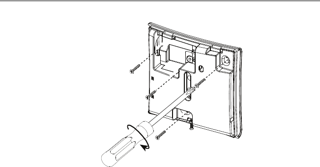
2.3 Permanently Mount
Once a suitable location is found, mount the HSM2HOST as follows:
1. Pull the Corbus wires through the holes at the back of the cabinet.
Hotkey Module Type
001 Keypads
002 Zone Expander
003 Output Module
006 HSM2Host
008 Audio Verification Module
009 Power Supply 1A
4
2. Mount the cabinet securely to the wall using the supplied 3 (three) screws.
Figure: 2.2 Mounting the HSM2HOST
2.4 Other Options
The following actions may be performed on the HSM2HOST, as well as other optional
modules.
2.4.1 [751] Delete Module
To remove a module from the alarm panel:
1. Enter the following Installer Programming section:
[751] (Delete Module) > Select module type: see Table 2-1 on page 3.
2. When prompted, press [*]. The module is deleted from the system.
2.4.2 [752] Confirm Module
This feature is used to confirm that a module is operational and also to help identify a spe-
cific module when more that one of the same type is enrolled.
To confirm a module:
1. Enter the following Installer Programming section:
[752] (Confirm Module) > Select module type: see Table 2-1 on page 3.
2. When prompted, press [*]. The module serial number is displayed on the keypad and
the red LED on the module flashes.
3. Press [#] to exit.
2.4.3 [753] Module Labels
To add a label to a module:
1. Enter the following Installer Programming section:
[753] (Module Labels) > Select module type: see Table 2-1 on page 3.
2. When prompted, key in a label to identify the module.
3. Press [#] to label another module or [#][#] to exit.
2.4.4 [804] Enroll Wireless Devices
Once the HSM2HOST is installed and enrolled on the alarm panel, wireless devices can be
enrolled using one of the following methods:
Auto enroll (use to enroll devices during installation):
1. Enter the following Installer Programming section:
[804] (Wireless Programming) > [000] (Add Wireless Devices)
2. Press [*]. When prompted, activate the device (see device installation sheet).
Placeholder Image
Not actual Product

5
The alarm panel determines the type of device being enrolled and presents the appro-
priate programming options.
Table 2-2 Wireless Device Options
3. Use the scroll keys or type in the corresponding number to select an option.
4. Scroll through the available selections, key in a number or enter text as appropriate.
5. Press [*] to accept and move to the next option.
6. Once all options are configured, the system prompts to enroll the next device.
Repeat the process described above until all wireless devices are enrolled.
NOTE: Configuration options for wireless devices are set using [804]>[201] Modify
Device.
Pre-enroll (use to enroll devices prior to installation)
Part 1:
1. Enter the following Installer Programming section:
[804] (Wireless Programming) > [000] (Add Wireless Devices)
2. Press [*]. When prompted, enter the device ESN.
The alarm panel determines the type of device being enrolled and presents the appro-
priate programming options (see Table 2-2).
3. Use the scroll keys or type in the corresponding number to select an option.
4. Scroll through the available selections, key in a number or enter text as appropriate.
5. Press [*] to accept and move to the next option.
6. Once all options are configured, the system prompts to pre-enroll the next device.
Repeat the process described above until all wireless devices are pre-enrolled.
Part 2:
Once at the installation site, activate the device to complete enrollment. The alarm panel
does not have to be in Installer Programming mode.
2.4.5 [101]-[104] Delete Wireless Devices
To delete wireless devices:
1. Enter Installer Programming section [804] (Wireless Programming) then select one
of the following sub-sections:
Table 2-3 Module Label Sub-Sections
2. Select a device to delete using the scroll keys or go directly to a specific device by
entering a hotkey.
Device Type Programming Options
Zone (01) Zone type
(02) Partition assignment
(03) Zone label
Wireless key (01) User label
Siren (01) Partition assignment
(02) Siren label
Repeater (01) Repeater Label
Sub-Section Description
101 Delete wireless zone devices
102 Delete Wireless key
103 Delete sirens
104 Delete repeaters

6
3. Press [*] to delete or [#] to exit.
2.5 Wireless Device Programming
The following wireless device programming options are available through section [804].
2.5.1 [201]-[204] Modify Wireless Device Setup Options
To modify wireless device setup options:
1. Enter Installer Programming section [804] (Wireless Programming) then navigate to
one of the following sub-sections using the scroll keys or by entering a hotkey:
Table 2-4 Modify Wireless Device Sub-Sections
2. Select a device to modify using the scroll keys or go directly to a specific device by
entering a hotkey.
3. Press [*] to select the device.
4. Press [#] to navigate to the Device Toggles screen then press [*]. The first available
option for the selected device is displayed.
5. Modify available device programming either by entering the hotkey or using the
scroll buttons.
6. Press [#] to move to the next configuration option. Once the last option has been
reached, pressing [#] exits the programming section.
See section Appendix 1: on page 20 for a complete list of available wireless configu-
ration options.
2.5.2 [301]-[304] Replace Wireless Devices
Use this option to replace a faulty device enrolled on the system with another device of
the same type while maintaining the configuration of the original. The faulty device does
not need to be deleted.
To replace a wireless device:
1. Enter Installer Programming section [804] (Wireless Programming) then select one
of the following sub-sections:
Table 2-5 Replace Device Sub-Sections
2. Press [*] to select a sub-section. A list of available options is displayed.
3. Press [*] to select a sub-section.
4. Select a device to replace using the scroll keys or go directly to a specific device by
entering a hotkey.
5. Press [*]. When prompted, activate the device (full enrollment) or enter the device
ID (pre-enrollment). A message is displayed confirming enrollment.
Sub-Section Description
201 Modify wireless zone devices
202 Modify wireless keys
203 Modify sirens
Sub-Section Description
301 Replace wireless zone devices
302 Replace wireless keys
303 Replace sirens
304 Replace repeater

7
2.5.3 [401]-[410] Wireless Device Defaults
Wireless device default parameters used during enrollment can be changed at any time.
Once default values are changed, any new devices enrolled inherit the modified default
values. The defaults of devices already enrolled are not changed.
To modify wireless device defaults:
1. Enter [*]>[8]>[804](Wireless Programming) then navigate to one of the following
sub-sections using the scroll keys or by entering a hotkey:
Table 2-6 Device Type Sub-Sections
2. Press [*] to select a sub-section. A list of available options is displayed.
3. Navigate the list of options using the scroll keys or by entering a hotkey, then press
[*] to select. The first programmable default is displayed.
4. Press [*] to select a default or to toggle it on or off.
5. Press [#] to move to the next available default. At the last default, pressing [#]
returns to the previous list of options.
See section Appendix 1: on page 20 for a complete list of available wireless configu-
ration options.
2.5.4 [501] RF Jam Detect
RF jam detection (continuous interfering transmissions on the radio network) can be
turned on or off. When on, RF jamming is logged and reported.
To configure RF jamming:
1. Enter Installer Programming section [804] (Wireless Programming)>[501] (Jam
Detect).
2. Select one of the following options by scrolling or entering the hotkey:
3. Press [*] to accept the selection.
4. Press [#] to exit the section.
2.5.5 [502] Wireless Supervision Window
This option is used to program the length of time a wireless device can be absent from the
system before a fault is generated.
Sub-Section Description
401 Contacts
402 Motion sensors
403 Glassbreak detectors
404 Smoke detectors
405 CO detectors
406 Gas detectors
407 Flood detectors
408 Temperature detectors
409 Wireless keys
410 Sirens
00 Enabled/Disabled Jamming detection and reporting is enabled/disabled
01 UL 20/20-USA Continuous RF jamming for 20 seconds
02 EN 30/60-Europe 30 seconds of accumulated jamming within 60 seconds
03 Class 6 30/60-British As EN (30/60) but reported only if the jamming duration
exceeds 5 minutes

8
NOTE: For EN installations, 1 hour or 2 hours must be selected.
To program the Wireless Supervisory Window:
1. Enter Installer Programming section [804] (Wireless Programming)>[502] (Wireless
Supervisory Window).
2. Select one of the following options by scrolling or entering the hotkey:
Table 2-7 Wireless Supervisory Window Options
3. Press [*] to accept the selection.
4. Press [#] to exit the section.
2.5.6 [510] Wireless Option 1
To program wireless options:
1. Enter Installer Programming section [804] (Wireless Programming)>[510] (Missing
Report).
2. Select one of the following options by scrolling or entering the hotkey:
Table 2-8 Wireless Options
3. Press [*] to accept the selection.
4. Press [#] to exit the section.
2.5.7 [600]-[604]Testing Wireless Devices
Wireless devices can be tested to verify RF signal status. Test all devices together or by
individual device type. The following test modes are available:
Table 2-9 Wireless Device Test Modes
00 Enabled/Disabled
01 After 1 Hour
02 After 2 Hour
03 After 4 Hour
04 After 8 Hour
05 After 12 Hour
06 After 24 Hour
01 RF Delinquency On: the system cannot be armed if a wireless supervisory
trouble exists.
Off: wireless supervisory troubles do not prevent arming.
02 Wireless Supervi-
sory/ RF Jam
Alarm
On: If a supervisory or jamming trouble occurs during
Away arming, the siren activates and the event is logged
and reported.
Off: supervisory or RF jam troubles during Away arming
do not activate the siren or get logged and reported.
03 Module Tamper On: device tampers are logged and reported.
Off: device tampers are not logged or reported.
04 200-second Fire
Supervisory On: fire devices are supervised every 200 seconds. If the
device fails to report within this window, a supervision
trouble is generated.
Off: fire devices follow the supervision window pro-
grammed in section 502.
600 Test all devices All enrolled wireless devices are tested automatically
in the following order: repeaters, sirens, detectors, key-
pads. View test results in section [610] Show All
Devices.
601 Test wireless zones Test wireless devices individually by zone.

9
Two test results are provided:
• 24-hour: Average signal status results received during a 24-hour period.
• Now: Signal status results of the current test.
The following status indicators may be displayed:
Table 2-10 Wireless Device Status Indications
[610] Show All Devices
The results of [600] Test all devices are displayed in this section. This section is only
available if a test has been completed.
[611] Show RF Problems
Similar to section [610] Show All Devices, except that only problematic test results are
displayed (i.e., Poor, 1-way, Not Test, Early).
2.5.8 [521]-[552] Programming Wireless Keys
To program wireless key buttons:
1. Enter Installer Programming section [804] (Wireless Programming)>[521]-[552]
(Wireless Key Buttons).
2. Select a wireless key to program (001-032) using the scroll keys or by entering a hot-
key.
3. Select one of the following options by scrolling or entering the hotkey:
Table 2-11 Wireless Key Button Programming Options
602 Test wireless keys Test individual wireless keys. Once in this section,
press a button on the wireless key to begin the test.
603 Test sirens Test each enrolled wireless siren.
604 Test repeaters Test each enrolled wireless repeater.
Strong Strong signal strength
Good Good signal strength
Poor Poor signal strength
1-Way The device is operating in 1-way mode only. The
alarm panel cannot configure or control the device
Not Test Displayed as the Now result if no test was per-
formed.
None Always displayed as the 24-hour result when testing
wireless keys.
Early Displayed as the 24-hour result when the panel has
been powered up for less than 24 hours.
00 Disabled 14 Global Disarm 34 User Programming
01 Stay Arm 17 Comm. Output 1 35 User Functions
02 Away Arm 18 Comm. Output 2 36 Reactivate Stay/
Away/Night
03 [*][9] No Entry 19 Comm. Output 3 37 Time/Date Prog.
04 Instant Stay Arm 20 Comm. Output 4 39 Trouble Display
05 Night Arm 27 Bypass Mode 40 Alarm Memory
07 Disarm 28 Bypass Recall 98 Aux. Alarm
09 Quick Exit 29 Bypass Group
Recall 99 Panic
11 Away No Entry 30 Quick Bypass
12 Global Stay Arm 32 Chime On/Off

10
4. Press [*] to accept the selection.
Press [#] to exit the section.
2.5.9 [700] Video Verification Programming
The central monitoring station can access video images from motion cameras to verify
Burglar, Fire or Panic alarms. Video can be transmitted in one of two ways:
• Video on demand: After receiving an alarm, the monitoring station can request
video verification.
• Video on alarm (default): Video is automatically transmitted to the monitoring sta-
tion when an alarm event occurs.
The following video verification options can be selected:
Table 2-12 Video Verification Programming Options
2.5.10 [997] View Module Information
This section is used to display the model, hardware revision and software version of the
HSM2HOST.
2.5.11 [999] Reset to Factory Defaults
Selecting this option resets all module programming to factory settings. Panel and other
module options are retained.
13 Global Away
Arm 33 System Test
View on Demand • Disable (Video on Alarm mode)
• All Arming Modes
• Away Arming Only
• Stay Arming Only
• Stay and Away Arming
• Disarm and Away Arming
• Disarm and Stay Arming
• Disarm Only
• View Time Window
• View Other Alarms
View Time Window
(video on demand)
•Always on
• Alarm + 5 minutes
• Alarm + 15 minutes
• Alarm + 1 hour
View Other Alarms
(non-burglar)
•Fire
• Duress code
•Emergency
•Panic
11
3. Programming Worksheets
This section is provided as a reference to available programming options and may also be
used to record custom settings. All programming sections below are accessed through
Installer Programming ([*][8]).
753 Module Labels
750 Enroll Module 000 - Auto Enroll
001 - Enroll Modules
751 Delete Module 001 - Delete Keypads
002 - Delete Zone Expander
003 - Delete Output Expander
006 - Delete HSM2HOST
008 - Delete Audio Verification
009 - Delete Power Supply
752 Confirm Module 001 - Confirm Keypads
002 - Confirm Zone Expander
003 - Confirm Output Expander
006 - Confirm HSM2HOST
008 - Confirm Audio Verification
009 - Confirm Power Supply
001 Keypad Labels (1 x 14 Characters)
001: 009:
002: 010:
003: 011:
004: 012:
005: 013:
006: 014:
007: 015:
008: 016:
002 Zone Expander Labels (1 x 14 Characters)
001: 009:
002: 010:
003: 011:
004: 012:
005: 013:
006: 014:
007: 015:
008: 016:
003 Output Expander Labels (1 x 14 Characters)
01:
006 HSM2HOST Label (1 x 14 Characters)
01:
008 HSM2955 Audio Verification Label (1 x 14 Characters)
01:

12
[802] Audio Programming
(See HSM2955 Installation Manual)
[804] Wireless Programming
009 HSM2300 Power Supply Label (1 x 14 Characters)
01:
020 Siren Label (1 x 14 Characters)
01:
021 Repeater Label (1 x 14 Characters)
01:
000 Enroll Wireless Device
01 - Zone
02 - Wireless Key
03 - Siren
04 - Repeater
101 Delete Devices
102 Delete Wireless Keys
103 Delete Sirens
104 Delete Repeaters
201 Modify Device
Zone Type:
Partition Assignment:
Device Toggles (contacts): Alarm LED
Reed Switch
Zone EOL: Disabled
Normally Open
Normally Closed
Single EOL
Device Toggles (Motion/PIR): Alarm LED
Event Counter
Black & White/Color
Image Resolution
Image Quality
Microphone
AC Power
Disarm Activity: Not Active
Yes -No De lay
Yes-5 Second Delay
Yes-15 Second Delay
Yes-30 Second Delay
Yes-1 Minute Delay
Yes-10 Minute Delay
Yes-60 Minute Delay
Image Brightness: Image Bright -3
Image Bright -2

13
Image Bright -1
Image Bright 0
Image Bright +1
Image Bright +2
Image Bright +3
Image Contrast: Image Contrast -3
Image Contrast -2
Image Contrast -1
Image Contrast 0
Image Contrast +1
Image Contrast +2
Image Contrast +3
Detection Range
(Microwave + non-microwave Motion)
Low Sensitivity
Mid Sensitivity
High Sensitivity
Detection Sensitivity Low Sensitivity
Mid Sensitivity
High Sensitivity
UL Standard
Unset Activity Unset Activity Time
Set Activity Set Activity Time
24Hr or Night Set Activity Time
Glassbreak
Smoke Burglary Siren
Fire Siren
Gas/CO Siren
Flood Siren
CO
Gas
Flood Alarm LED
Temperature Alarm LED
Temperature °C
Ve ry Ho t
Hot
Cold
Ve ry Co ld
Freezing
Freezer
Zone Label
001-128 (See User Manual)

14
202 Wireless Key
Available programming options:
00- Disabled
01- Stay Arm
02- Away Arm
03- [*][9] No Entry
04- Instant Stay Arm
05- Night Arm
07- Disarm
09- Quick Exit
11- Away No Entry
12- Global Stay Arm
13- Global Away Arm
14- Global Disarm
17- Comm. Output 1
18- Comm. Output 2
19- Comm. Output 3
20- Comm. Output 4
27- Bypass Mode
28- Bypass Recall
29- Bypass Group Recall
30- Quick Bypass
32- Chime On/Off
33- System Test
34- User Programming
35- User Functions
36- Reactivate Stay/Away/Night
37- Time/Date Prog.
39- Trouble Display
10- Alarm Memory
98- Aux. Alarm
99- Panic
01: 05: 09: 13: 17: 21: 25: 29:
02: 06: 10: 14: 18: 22: 26: 30:
03: 07: 11: 15: 19: 23: 27: 31:
04: 08: 12: 16: 20: 24: 28: 32:
203 Modify Siren
Device Toggles Auto Tmp Alarm
AC Power
Smash Alarm
Strobe Alarm Disabled
Timer Limited
Until Disarmed
Exit-Entry Beeps Disabled
Enabled
Disabled Stay
Squawk Disabled
Sounder Only
Strobe Only
Sounder + Strobe
Sounder Volume Low
Medium
High
301 Replace Device 301 - Replace Zone Device
302 - Replace Wireless Key
303 - Replace Siren
304 - Replace Repeater
401 Default Set Contact
Device Toggles Alarm LED
402 Set Motion Default Alarm LED
Event Counter
Black & White/Color
Image Resolution
Image Quality

15
Microphone
AC Power
Disarm Activity: Not Active
Yes -No De lay
Yes-5 Second Delay
Yes-15 Second Delay
Yes-30 Second Delay
Yes-1 Minute Delay
Yes-10 Minute Delay
Yes-60 Minute Delay
Image Brightness: Image Bright -3
Image Bright -2
Image Bright -1
Image Bright 0
Image Bright +1
Image Bright +2
Image Bright +3
Image Contrast: Image Contrast -3
Image Contrast -2
Image Contrast -1
Image Contrast 0
Image Contrast +1
Image Contrast +2
Image Contrast +3
Detection Range
(Microwave + non-microwave Motion)
Low Sensitivity
Mid Sensitivity
High Sensitivity
Detection Sensitivity Low Sensitivity
Mid Sensitivity
High Sensitivity
UL Standard
Unset Activity Unset Activity Time
Set Activity Set Activity Time
24Hr or Night Set Activity Time
403 Set Glassbreak Default
404 Set Smoke Default Burglary Siren
Fire Siren
Gas/CO Siren
Flood Siren
405 Set CO Default
406 Set Gas Default
407 Set Flood Default Alarm LED
408 Set Temperature Default Alarm LED
Temperature °C
Ve ry Ho t

16
Hot
Cold
Ve ry Co ld
Freezing
Freezer
409 Set Wireless Key Default (See section 521 for options)
01: 05: 09: 13: 17: 21: 25: 29:
02: 06: 10: 14: 18: 22: 26: 30:
03: 07: 11: 15: 19: 23: 27: 31:
04: 08: 12: 16: 20: 24: 28: 32:
410 Set Siren Default
Device Toggles Auto Tmp Alarm
AC Power
Smash Alarm
Strobe Alarm Disabled
Timer Limited
Until Disarmed
Exit-Entry Beeps Disabled
Enabled
Disabled Stay
Squawk Disabled
Sounder Only
Strobe Only
Sounder + Strobe
Sounder Volume Low
Medium
High
501 Jam Detect Disabled
UL 20/20
EN 30/60
Class 6 (30/60)
502 Missing Report Disabled
After 1 Hour
After 2 Hour
After 4 Hour
After 8 Hour
After 12 Hour
After 24 Hour
510 Wireless Options 1 Not Ready
EN Standard
Wireless Tamper
200-Second Fire Supervisory

17
521-
552
Wireless Key Programming
Available programming options:
00- Disabled
01- Stay Arm
02- Away Arm
03- [*][9] No Entry
04- Instant Stay Arm
05- Night Arm
07- Disarm
09- Quick Exit
11- Away No Entry
12- Global Stay Arm
13- Global Away Arm
14- Global Disarm
17- Comm. Output 1
18- Comm. Output 2
19- Comm. Output 3
20- Comm. Output 4
27- Bypass Mode
28- Bypass Recall
29- Bypass Group Recall
30- Quick Bypass
32- Chime On/Off
33- System Test
34- User Programming
35- User Functions
36- Reactivate Stay/Away/Night
37- Time/Date Prog.
39- Trouble Display
10- Alarm Memory
98- Aux. Alarm
99- Panic
521: 525: 529: 533: 537: 541: 545: 549:
522: 526: 530: 534: 538: 542: 546: 550:
523: 527: 531: 535: 539: 543: 547: 551:
524: 528: 532: 536: 540: 544: 548: 552:
600 Test All Devices
601 Test Wireless Zones
602 Test Wireless Keys
603 Test Sirens
604 Test Repeaters
610 Show All Devices
611 Show RF Problems
700 Motion Cameras (Video on Demand)
View on Demand Disabled
In All Modes
Away Only
Stay Only
Stay and Away
Disarm & Away
Disarm & Home
Disarmed Only
View Time Window Always
Alarm + 5 Minutes
Alarm + 15 Minutes
Alarm + 1 Hour
View Other Alarm Fire
Duress
Medical
Panic
997 Module Information Model Name
Software Version
Hardware Version
999 Default HSM2HOST

18
8XX Keypad Programming
Keypad Partition Mask Global Keypad
Partition
Function Key Programming:
01 - Null Key 16 - Local PGM Active 32 - Chime On/Off
02 - Stay Arm 17 - Command Output 1 33 - System Test
03 - No Entry Arm 18 - Command Output 2 34 - User Programming
04 - Instant Stay Arm 19 - Command Output 3 35 - User Functions
05 - Night Arm 20 - Command Output 4 36 - React Sty/Awy/Ng
09 - Quick Exit 27 - Bypass Mode 37 - Time/Date Prog
12 - Global Stay Arm 28 - Bypass Recall 39 - Trouble Display
13 - Global Away Arm 29 - Bypass Group Recall 40 - Alarm Memory
14 - Global Disarming 30 - Quick Bypass XX - Partition XX Sel
(01) Keypad I/O 1 Input:
Output:
(021) Keypad Option 1 01 - F Key Enabled
02 - A Key Enabled
03 - P Key Enabled
04 - Display Code
(22) Keypad Option 2 Local Clock
Clock 24-Hour
Auto Alarm Memory Screen
Language Select
Power LED
Power LED AC
Alarm Dis Arm
Auto Scroll Op Zn
(023) Keypad Option 3 01 - Arm LED Power Save
07 - Local Temperature
08 - Low Temperature Warning
(030) LCD Message:
(031) LCD Message Duration (000-255):
(41) Indoor Temperature Temperature Zone (000-XXX):
(042) Outdoor Temperature Temperature Zone (000-XXX):
(101) Zone X Door Chime 6 Beeps
Bing Bong
Ding Dong
Zone Name
899 Template Programming Template Code:
Phone Number:
System Account #:
Partition 1 Account #:
DLS Access Code:
Entry Delay 1:
Exit Delay:

19
900 System Info
00 - Alarm System 471 - Printer
001 - Keypads 481 - Audio Verification
101 - 8-Zone Expander 491 - Alternate Comm.
201 - Output Expander 501 - Power Supply
461 - HSM2Host 521 - High-Current Output
901 Installer Walktest
902 Zone Soak Test 000 - Soak Test Duration (001-255 Days):
001/0128 - Zone 1-128 soak test
989 Default Master Code
990 Installer Lockout Enabled
991 Default Keypads 000 - Default All Keypads
0XX - Default Keypad XX
992 Default Zone Expander Default All
Default Zone Expander XX
993 Default Alternate Communicator
996 Default HSM2HOST
999 Default System 001 - Default System
002 - Default Labels

20
Appendix 1: Wireless Device
Configuration Options
[*]>[8]>[804]Wireless Programming>[201]-[204] Device Toggles
Section Sub-
Section Device Type Option 1 Option 2
(201)
Modify
Wireless
Zone
Device
(001) Contacts
(Toggles)
(01) Alarm LED
(02) Reed Switch
(002) Contacts
(Zone EOL)
(01) Disabled
(02) Normally Open
(03) Normally Closed
(04) Single EOL
(003) Motion/PIR (01) Alarm LED
(02) Event Counter
(03) Black & White/Color
(04) Image Resolution
(05) Image Quality
(06) Microphone
(07) AC Power
(004) PIR Cameras (01) Disarm Activity (01) Not Active
(02) Yes-No Delay
(03) Yes + 5 second Delay
(04) Yes + 15 second Delay
(05) Yes + 30 second Delay
(06) Yes + 1 minute Delay
(07) Yes + 10 minute Delay
(08) Yes + 60 minute Delay
(02) Image Brightness (01) Image Bright -3
(02) Image Bright -2
(03) Image Bright -1
(04) Image Bright 0
(05) Image Bright +1
(06) Image Bright +2
(07) Image Bright +3
(03) Image Contrast (01) Image Contrast -3
(02) Image Contrast -2
(03) Image Contrast -1
(04) Image Contrast 0
(05) Image Contrast +1
(06) Image Contrast +2
(07) Image Contrast +3
(005) Microwave + non-
microwave Motion
(01) Detection Range (01) Low Sensitivity
(02) Mid Sensitivity
(03) High Sensitivity
(02) Detection Sensitivity (01) Low Sensitivity
(02) Mid Sensitivity
(03) High Sensitivity
(04) UL Standard
(03) Unset Activity (01) Unset Activity Time
(04) Set Activity (01) Set Activity Time
(05) 24Hr or Night (01) Set Act Time
(006) Glassbreak
(007) Smoke (01) Burglary Siren
(02) Fire Siren
(03) Gas/CO Siren
(04) Flood Siren
(008) CO

21
(009) Gas
(010) Flood (01) Alarm LED
(011) Temperature (01) Alarm LED
(02) Temperature °C
(03) Very Hot
(04) Hot
(05) Cold
(06) Very Cold
(07) Freezing
(08) Freezer
(202)
Modify
Siren
(001) Wireless Siren (01) Device Toggles (01) Auto Tmp Alarm
(02) AC Power
(03) Smash Alarm
(02) Strobe Alarm (01) Disabled
(02) Timer Limited
(03) Until Disarmed
(03) Exit-Entry Beeps (01) Disabled
(02) Enabled
(03) Disabled Stay
(04) Squawk (01) Disabled
(02) Sounder Only
(03) Strobe Only
(04) Sounder + Strobe
(05) Sounder Volume (01) Low
(02) Medium
(03) High
Section Sub-
Section Device Type Option 1 Option 2

22
Warning Please Read Carefully
Note to Installers
This warning contains vital information. As the only individual in contact with system users, it is your responsibility to bring each item in this
warning to the attention of the users of this system.
System Failures
This system has been carefully designed to be as effective as possible. There are circumstances, however, involving fire, burglary, or other
types of emergencies where it may not provide protection. Any alarm system of any type may be compromised deliberately or may fail to
operate as expected for a variety of reasons. Some but not all of these reasons may be:
• Inadequate Installation
A security system must be installed properly in order to provide adequate protection. Every installation should be evaluated by a security pro-
fessional to ensure that all access points and areas are covered. Locks and latches on windows and doors must be secure and operate as
intended. Windows, doors, walls, ceilings and other building materials must be of sufficient strength and construction to provide the level of
protection expected. A reevaluation must be done during and after any construction activity. An evaluation by the fire and/or police depart-
ment is highly recommended if this service is available.
• Criminal Knowledge
This system contains security features which were known to be effective at the time of manufacture. It is possible for persons with criminal
intent to develop techniques which reduce the effectiveness of these features. It is important that a security system be reviewed periodically to
ensure that its features remain effective and that it be updated or replaced if it is found that it does not provide the protection expected.
• Access by Intruders
Intruders may enter through an unprotected access point, circumvent a sensing device, evade detection by moving through an area of insuffi-
cient coverage, disconnect a warning device, or interfere with or prevent the proper operation of the system.
• Power Failure
Control units, intrusion detectors, smoke detectors and many other security devices require an adequate power supply for proper operation. If
a device operates from batteries, it is possible for the batteries to fail. Even if the batteries have not failed, they must be charged, in good con-
dition and installed correctly. If a device operates only by AC power, any interruption, however brief, will render that device inoperative while
it does not have power. Power interruptions of any length are often accompanied by voltage fluctuations which may damage electronic equip-
ment such as a security system. After a power interruption has occurred, immediately conduct a complete system test to ensure that the system
operates as intended.
• Failure of Replaceable Batteries
This system’s wireless transmitters have been designed to provide several years of battery life under normal conditions. The expected battery
life is a function of the device environment, usage and type. Ambient conditions such as high humidity, high or low temperatures, or large
temperature fluctuations may reduce the expected battery life. While each transmitting device has a low battery monitor which identifies when
the batteries need to be replaced, this monitor may fail to operate as expected. Regular testing and maintenance will keep the system in good
operating condition.
• Compromise of Radio Frequency (Wireless) Devices
Signals may not reach the receiver under all circumstances which could include metal objects placed on or near the radio path or deliberate
jamming or other inadvertent radio signal interference.
• System Users
A user may not be able to operate a panic or emergency switch possibly due to permanent or temporary physical disability, inability to reach
the device in time, or unfamiliarity with the correct operation. It is important that all system users be trained in the correct operation of the
alarm system and that they know how to respond when the system indicates an alarm.
• Smoke Detectors
Smoke detectors that are a part of this system may not properly alert occupants of a fire for a number of reasons, some of which follow. The
smoke detectors may have been improperly installed or positioned. Smoke may not be able to reach the smoke detectors, such as when the fire
is in a chimney, walls or roofs, or on the other side of closed doors. Smoke detectors may not detect smoke from fires on another level of the
residence or building.
Every fire is different in the amount of smoke produced and the rate of burning. Smoke detectors cannot sense all types of fires equally well.
Smoke detectors may not provide timely warning of fires caused by carelessness or safety hazards such as smoking in bed, violent explosions,
escaping gas, improper storage of flammable materials, overloaded electrical circuits, children playing with matches or arson.
Even if the smoke detector operates as intended, there may be circumstances when there is insufficient warning to allow all occupants to
escape in time to avoid injury or death.
• Motion Detectors
Motion detectors can only detect motion within the designated areas as shown in their respective installation instructions. They cannot dis-
criminate between intruders and intended occupants. Motion detectors do not provide volumetric area protection. They have multiple beams
of detection and motion can only be detected in unobstructed areas covered by these beams. They cannot detect motion which occurs behind
walls, ceilings, floor, closed doors, glass partitions, glass doors or windows. Any type of tampering whether intentional or unintentional such
as masking, painting, or spraying of any material on the lenses, mirrors, windows or any other part of the detection system will impair its
proper operation.
Passive infrared motion detectors operate by sensing changes in temperature. However their effectiveness can be reduced when the ambient
temperature rises near or above body temperature or if there are intentional or unintentional sources of heat in or near the detection area. Some
of these heat sources could be heaters, radiators, stoves, barbeques, fireplaces, sunlight, steam vents, lighting and so on.
• Warning Devices
Warning devices such as sirens, bells, horns, or strobes may not warn people or waken someone sleeping if there is an intervening wall or
door. If warning devices are located on a different level of the residence or premise, then it is less likely that the occupants will be alerted or
awakened. Audible warning devices may be interfered with by other noise sources such as stereos, radios, televisions, air conditioners or other
appliances, or passing traffic. Audible warning devices, however loud, may not be heard by a hearing-impaired person.
• Telephone Lines
If telephone lines are used to transmit alarms, they may be out of service or busy for certain periods of time. Also an intruder may cut the tele-
phone line or defeat its operation by more sophisticated means which may be difficult to detect.
• Insufficient Time
There may be circumstances when the system will operate as intended, yet the occupants will not be protected from the emergency due to their
inability to respond to the warnings in a timely manner. If the system is monitored, the response may not occur in time to protect the occupants
or their belongings.
• Component Failure
Although every effort has been made to make this system as reliable as possible, the system may fail to function as intended due to the failure
of a component.
• Inadequate Testing
Most problems that would prevent an alarm system from operating as intended can be found by regular testing and maintenance. The com-
plete system should be tested weekly and immediately after a break-in, an attempted break-in, a fire, a storm, an earthquake, an accident, or
any kind of construction activity inside or outside the premises. The testing should include all sensing devices, keypads, consoles, alarm indi-
cating devices and any other operational devices that are part of the system.
• Security and Insurance
Regardless of its capabilities, an alarm system is not a substitute for property or life insurance. An alarm system also is not a substitute for property owners, renters, or other occupants to act
prudently to prevent or minimize the harmful effects of an emergency situation.

23
IMPORTANT - READ CAREFULLY: DSC Software purchased with or without Products and
Components is copyrighted and is purchased under the following license terms:
• This End-User License Agreement (“EULA”) is a legal agreement between You (the company, individual or entity
who acquired the Software and any related Hardware) and Digital Security Controls, a division of Tyco Safety
Products Canada Ltd. (“DSC”), the manufacturer of the integrated security systems and the developer of the
software and any related products or components (“HARDWARE”) which You acquired.
• If the DSC software product (“SOFTWARE PRODUCT” or “SOFTWARE”) is intended to be accompanied by
HARDWARE, and is NOT accompanied by new HARDWARE, You may not use, copy or install the SOFTWARE
PRODUCT. The SOFTWARE PRODUCT includes computer software, and may include associated media, printed
materials, and “online” or electronic documentation.
• Any software provided along with the SOFTWARE PRODUCT that is associated with a separate end-user license
agreement is licensed to You under the terms of that license agreement.
• By installing, copying, downloading, storing, accessing or otherwise using the SOFTWARE PRODUCT, You agree
unconditionally to be bound by the terms of this EULA, even if this EULA is deemed to be a modification of any
previous arrangement or contract. If You do not agree to the terms of this EULA, DSC is unwilling to license the
SOFTWARE PRODUCT to You, and You have no right to use it.
SOFTWARE PRODUCT LICENSE
The SOFTWARE PRODUCT is protected by copyright laws and international copyright treaties, as well as other
intellectual property laws and treaties. The SOFTWARE PRODUCT is licensed, not sold.
1. GRANT OF LICENSE This EULA grants You the following rights:
(a) Software Installation and Use - For each license You acquire, You may have only one copy of the SOFTWARE
PRODUCT installed.
(b) Storage/Network Use - The SOFTWARE PRODUCT may not be installed, accessed, displayed, run, shared or
used concurrently on or from different computers, including a workstation, terminal or other digital electronic
device (“Device”). In other words, if You have several workstations, You will have to acquire a license for each
workstation where the SOFTWARE will be used.
(c) Backup Copy - You may make back-up copies of the SOFTWARE PRODUCT, but You may only have one copy
per license installed at any given time. You may use the back-up copy solely for archival purposes. Except as
expressly provided in this EULA, You may not otherwise make copies of the SOFTWARE PRODUCT, including
the printed materials accompanying the SOFTWARE.
2. DESCRIPTION OF OTHER RIGHTS AND LIMITATIONS
(a) Limitations on Reverse Engineering, Decompilation and Disassembly - You may not reverse engineer,
decompile, or disassemble the SOFTWARE PRODUCT, except and only to the extent that such activity is
expressly permitted by applicable law notwithstanding this limitation. You may not make any changes or
modifications to the Software, without the written permission of an officer of DSC. You may not remove any
proprietary notices, marks or labels from the Software Product. You shall institute reasonable measures to ensure
compliance with the terms and conditions of this EULA.
(b) Separation of Components - The SOFTWARE PRODUCT is licensed as a single product. Its component parts
may not be separated for use on more than one HARDWARE unit.
(c) Single INTEGRATED PRODUCT - If You acquired this SOFTWARE with HARDWARE, then the
SOFTWARE PRODUCT is licensed with the HARDWARE as a single integrated product. In this case, the
SOFTWARE PRODUCT may only be used with the HARDWARE as set forth in this EULA..
(d) Rental - You may not rent, lease or lend the SOFTWARE PRODUCT. You may not make it available to others or
post it on a server or web site.
(e) Software Product Transfer - You may transfer all of Your rights under this EULA only as part of a permanent
sale or transfer of the HARDWARE, provided You retain no copies, You transfer all of the SOFTWARE
PRODUCT (including all component parts, the media and printed materials, any upgrades and this EULA), and
provided the recipient agrees to the terms of this EULA. If the SOFTWARE PRODUCT is an upgrade, any transfer
must also include all prior versions of the SOFTWARE PRODUCT.
(f) Termination - Without prejudice to any other rights, DSC may terminate this EULA if You fail to comply with the
terms and conditions of this EULA. In such event, You must destroy all copies of the SOFTWARE PRODUCT and
all of its component parts.
(g) Trademarks - This EULA does not grant You any rights in connection with any trademarks or service marks of
DSC or its suppliers.
3. COPYRIGHT - All title and intellectual property rights in and to the SOFTWARE PRODUCT (including but
not limited to any images, photographs, and text incorporated into the SOFTWARE PRODUCT), the
accompanying printed materials, and any copies of the SOFTWARE PRODUCT, are owned by DSC or its
suppliers. You may not copy the printed materials accompanying the SOFTWARE PRODUCT. All title and
intellectual property rights in and to the content which may be accessed through use of the SOFTWARE
PRODUCT are the property of the respective content owner and may be protected by applicable copyright or
other intellectual property laws and treaties. This EULA grants You no rights to use such content. All rights not
expressly granted under this EULA are reserved by DSC and its suppliers.
4. EXPORT RESTRICTIONS - You agree that You will not export or re-export the SOFTWARE
PRODUCT to any country, person, or entity subject to Canadian export restrictions.
5. CHOICE OF LAW - This Software License Agreement is governed by the laws of the Province of Ontario, Canada.
6. ARBITRATION - All disputes arising in connection with this Agreement shall be determined by final and
binding arbitration in accordance with the Arbitration Act, and the parties agree to be bound by the arbitrator’s
decision. The place of arbitration shall be Toronto, Canada, and the language of the arbitration shall be
English.
7. LIMITED WARRANTY
(a) NO WARRANTY - DSC PROVIDES THE SOFTWARE “AS IS” WITHOUT WARRANTY. DSC DOES NOT
WARRANT THAT THE SOFTWARE WILL MEET YOUR REQUIREMENTS OR THAT OPERATION OF THE
SOFTWARE WILL BE UNINTERRUPTED OR ERROR-FREE.
(b) CHANGES IN OPERATING ENVIRONMENT - DSC shall not be responsible for problems caused by
changes in the operating characteristics of the HARDWARE, or for problems in the interaction of the SOFTWARE
PRODUCT with non-DSC-SOFTWARE or HARDWARE PRODUCTS.
(c) LIMITATION OF LIABILITY; WARRANTY REFLECTS ALLOCATION OF RISK - IN ANY EVENT,

24
IF ANY STATUTE IMPLIES WARRANTIES OR CONDITIONS NOT STATED IN THIS LICENSE
AGREEMENT, DSC’S ENTIRE LIABILITY UNDER ANY PROVISION OF THIS LICENSE AGREEMENT
SHALL BE LIMITED TO THE GREATER OF THE AMOUNT ACTUALLY PAID BY YOU TO LICENSE THE
SOFTWARE PRODUCT AND FIVE CANADIAN DOLLARS (CAD$5.00). BECAUSE SOME JURISDICTIONS
DO NOT ALLOW THE EXCLUSION OR LIMITATION OF LIABILITY FOR CONSEQUENTIAL OR
INCIDENTAL DAMAGES, THE ABOVE LIMITATION MAY NOT APPLY TO YOU.
(d) DISCLAIMER OF WARRANTIES - THIS WARRANTY CONTAINS THE ENTIRE WARRANTY AND
SHALL BE IN LIEU OF ANY AND ALL OTHER WARRANTIES, WHETHER EXPRESSED OR IMPLIED
(INCLUDING ALL IMPLIED WARRANTIES OF MERCHANTABILITY OR FITNESS FOR A PARTICULAR
PURPOSE) AND OF ALL OTHER OBLIGATIONS OR LIABILITIES ON THE PART OF DSC. DSC MAKES
NO OTHER WARRANTIES. DSC NEITHER ASSUMES NOR AUTHORIZES ANY OTHER PERSON
PURPORTING TO ACT ON ITS BEHALF TO MODIFY OR TO CHANGE THIS WARRANTY, NOR TO
ASSUME FOR IT ANY OTHER WARRANTY OR LIABILITY CONCERNING THIS SOFTWARE PRODUCT.
(e) EXCLUSIVE REMEDY AND LIMITATION OF WARRANTY - UNDER NO CIRCUMSTANCES
SHALL DSC BE LIABLE FOR ANY SPECIAL, INCIDENTAL, CONSEQUENTIAL OR INDIRECT
DAMAGES BASED UPON BREACH OF WARRANTY, BREACH OF CONTRACT, NEGLIGENCE, STRICT
LIABILITY, OR ANY OTHER LEGAL THEORY. SUCH DAMAGES INCLUDE, BUT ARE NOT LIMITED
TO, LOSS OF PROFITS, LOSS OF THE SOFTWARE PRODUCT OR ANY ASSOCIATED EQUIPMENT,
COST OF CAPITAL, COST OF SUBSTITUTE OR REPLACEMENT EQUIPMENT, FACILITIES OR
SERVICES, DOWN TIME, PURCHASERS TIME, THE CLAIMS OF THIRD PARTIES, INCLUDING
CUSTOMERS, AND INJURY TO PROPERTY. WARNING: DSC recommends that the entire system be
completely tested on a regular basis. However, despite frequent testing, and due to, but not limited to,
criminal tampering or electrical disruption, it is possible for this SOFTWARE PRODUCT to fail to perform
as expected.
Limited Warranty
Digital Security Controls warrants the original purchaser that for a period of twelve months from the date of purchase, the product shall be free
of defects in materials and workmanship under normal use. During the warranty period, Digital Security Controls shall, at its option, repair or
replace any defective product upon return of the product to its factory, at no charge for labour and materials. Any replacement and/or repaired
parts are warranted for the remainder of the original warranty or ninety (90) days, whichever is longer. The original purchaser must promptly
notify Digital Security Controls in writing that there is defect in material or workmanship, such written notice to be received in all events prior
to expiration of the warranty period. There is absolutely no warranty on software and all software products are sold as a user license under the
terms of the software license agreement included with the product. The Customer assumes all responsibility for the proper selection, installa-
tion, operation and maintenance of any products purchased from DSC. Custom products are only warranted to the extent that they do not func-
tion upon delivery. In such cases, DSC can replace or credit at its option.
International Warranty
The warranty for international customers is the same as for any customer within Canada and the United States, with the exception that Digital
Security Controls shall not be responsible for any customs fees, taxes, or VAT that may be due.
Warranty Procedure
To obtain service under this warranty, please return the items) in question to the point of purchase. All authorized distributors and dealers have
a warranty program. Anyone returning goods to Digital Security Controls must first obtain an authorization number. Digital Security Controls
will not accept any shipment whatsoever for which prior authorization has not been obtained.
Conditions to Void Warranty
This warranty applies only to defects in parts and workmanship relating to normal use. It does not cover:
• damage incurred in shipping or handling;
• damage caused by disaster such as fire, flood, wind, earthquake or lightning;
• damage due to causes beyond the control of Digital Security Controls such as excessive voltage, mechanical shock or water damage;
• damage caused by unauthorized attachment, alterations, modifications or foreign objects;
• damage caused by peripherals (unless such peripherals were supplied by Digital Security Controls);
• defects caused by failure to provide a suitable installation environment for the products;
• damage caused by use of the products for purposes other than those for which it was designed;
• damage from improper maintenance;
• damage arising out of any other abuse, mishandling or improper application of the products.
Items Not Covered by Warranty
In addition to the items which void the Warranty, the following items shall not be covered by Warranty: (i) freight cost to the repair centre; (ii)
products which are not identified with DSC's product label and lot number or serial number; (iii) products disassembled or repaired in such a
manner as to adversely affect performance or prevent adequate inspection or testing to verify any warranty claim. Access cards or tags
returned for replacement under warranty will be credited or replaced at DSC's option. Products not covered by this warranty, or otherwise out
of warranty due to age, misuse, or damage shall be evaluated, and a repair estimate shall be provided. No repair work will be performed until
a valid purchase order is received from the Customer and a Return Merchandise Authorisation number (RMA) is issued by DSC's Customer
Service.
Digital Security Controls’s liability for failure to repair the product under this warranty after a reasonable number of attempts will be limited to
a replacement of the product, as the exclusive remedy for breach of warranty. Under no circumstances shall Digital Security Controls be liable
for any special, incidental, or consequential damages based upon breach of warranty, breach of contract, negligence, strict liability, or any
other legal theory. Such damages include, but are not limited to, loss of profits, loss of the product or any associated equipment, cost of capital,
cost of substitute or replacement equipment, facilities or services, down time, purchaser’s time, the claims of third parties, including custom-
ers, and injury to property. The laws of some jurisdictions limit or do not allow the disclaimer of consequential damages. If the laws of such a
jurisdiction apply to any claim by or against DSC, the limitations and disclaimers contained here shall be to the greatest extent permitted by
law. Some states do not allow the exclusion or limitation of incidental or consequential damages, so that the above may not apply to you.
Disclaimer of Warranties
This warranty contains the entire warranty and shall be in lieu of any and all other warranties, whether expressed or implied (including all
implied warranties of merchantability or fitness for a particular purpose) and of all other obligations or liabilities on the part of Digital Security
Controls. Digital Security Controls neither assumes responsibility for nor authorizes any other person purporting to act on its behalf to modify
or to change this warranty, nor to assume for it any other warranty or liability concerning this product.
This disclaimer of warranties and limited warranty are governed by the laws of the province of Ontario, Canada.
WARNING: Digital Security Controls recommends that the entire system be completely tested on a regular basis. However, despite frequent
testing, and due to, but not limited to, criminal tampering or electrical disruption, it is possible for this product to fail to perform as expected.
Out of Warranty Repairs
Digital Security Controls will at its option repair or replace out-of-warranty products which are returned to its factory according to the follow-
ing conditions. Anyone returning goods to Digital Security Controls must first obtain an authorization number. Digital Security Controls will
not accept any shipment whatsoever for which prior authorization has not been obtained.
Products which Digital Security Controls determines to be repairable will be repaired and returned. A set fee which Digital Security Controls
has predetermined and which may be revised from time to time, will be charged for each unit repaired.
IC Statement
This device complies with Industry Canada licence-exempt RSS standard(s). Operation is subject to the following two conditions: (1)
this device may not cause interference, and (2) this device must accept any interference, including interference that may cause undesired
operation of the device.
Le présent appareil est conforme aux CNR d'Industrie Canada applicables aux appareils radio exempts de licence. L'exploitation est
autorisée aux deux conditions suivantes : (1) l'appareil ne doit pas produire de brouillage, et (2) l'utilisateur de l'appareil doit accepter
tout brouillage radioélectrique subi, même si le brouillage est susceptible d'en compromettre le fonctionnement.
FCC Compliance Statement
CAUTION: Changes or modifications not expressly approved by Digital
Security Controls could void your authority to use this equipment.
This equipment generates and uses radio frequency energy and if not installed
and used properly, in strict accordance with the manufacturer’s instructions,
may cause interference to radio and television reception. It has been type tested
and found to comply with the limits for Class B device in accordance with the
specifications in Subpart “B” of Part 15 of FCC Rules, which are designed to
provide reasonable protection against such interference in any residential
installation. However, there is no guarantee that interference will not occur in a
particular installation. If this equipment does cause interference to television or
radio reception, which can be determined by turning the equipment off and on,
the user is encouraged to try to correct the interference by one or more of the
following measures:
• Re-orient the receiving antenna
• Relocate the alarm control with respect to the receiver
• Move the alarm control away from the receiver
• Connect the alarm control into a different outlet so the alarm control &
receiver are on different circuits.
If necessary, the user should consult the dealer or an experienced radio/television technician for additional suggestions. The user may find the following
booklet prepared by the FCC helpful: “How to Identify and Resolve Radio/Television Interference Problems”. This booklet is available from the U.S.
Government Printing Office, Washington, D.C. 20402, Stock # 004-000-00345-4.
This Class B digital apparatus meets all requirements of the Canadian interference-causing equipment regulations.
Cet appareil numérique de la Classe B respecte toutes les exigences de règlement sur le matériel brouilleur du Canada.
IC:160A-HS2HOST9
The term ‘IC:’ before the radio certification number only signifies that Industry Canada technical specifications were met.
© 2012 Tyco International Ltd. et ses compagnies respectives. Tous droits réservés.
© 2012 Tyco International Ltd. y sus respectivas compañías. Todos los derechos reservados.
© 2012 Tyco International Ltd. e suas Respectivas Empresas. Todos os Direitos Reservados.
© 2012 Tyco International Ltd. and its Respective Companies. All Rights Reserved.
Toronto, Canada • www.dsc.com
Tech. Support/Centre d’aide technique/Líneas Tech: 1-800-387-3630 (Canada, US), 905-760-3000
Printed in Canada / Imprimé au Canada / Impreso en Canadá / Impresso no Canadá
+HUHE\ '6& GHFODUHV WKDW WKLV GHYLFH LV LQ FRPSOLDQFH ZLWK WKH HVVHQWLDO
UHTXLUHPHQWVDQGRWKHUUHOHYDQWSURYLVLRQVRI'LUHFWLYH(&
7KH FRPSOHWH 577( 'HFODUDWLRQ RI &RQIRUPLW\ FDQ EH IRXQG DW
KWWSZZZGVFFRPOLVWLQJVBLQGH[DVS[
&=( '6& MDNR Y¿UREFH SURKODģXMH ŀH WHQWR Y¿UREHN MH Y VRXODGX VH YģHPL
UHOHYDQWQ¯PLSRŀDGDYN\VPÝUQLFH(&
'$1'6&HUNO¨UHUKHUYHGDWGHQQHNRPSRQHQWHQRYHUKROGHUDOOHYLNWLJHNUDYVDPW
DQGUHEHVWHPPHOVHUJLWWLGLUHNWLY(&
'87 +LHUELM YHUNODDUW '6& GDW GLW WRHVWHO LQ RYHUHHQVWHPPLQJ LV PHW GH HLVHQ HQ
EHSDOLQJHQYDQULFKWOLMQ(&
),1'6&YDNXXWWDDODLWWHHQW¦\WW¦Y¦QGLUHNWLLYLQ(&ROHQQDLVHWYDDWLPXNVHW
)5( 3DU OD SU«VHQWH '6& G«FODUH TXH FH GLVSRVLWLI HVW FRQIRUPH DX[ H[LJHQFHV
HVVHQWLHOOHVHWDXWUHVVWLSXODWLRQVSHUWLQHQWHVGHOD'LUHFWLYH(&
*(5+LHUGXUFKHUNO¦UW'6&GD¡GLHVHV*HU¦WGHQHUIRUGHUOLFKHQ%HGLQJXQJHQXQG
9RUUDXVHW]XQJHQGHU5LFKWOLQLH(&HQWVSULFKW
*5(˂˜˞˱ˬ˲ ˭˞ˮ˹˪˱ˬ˯ˤ'6&ˡˤ˨˻˪ˢ˦ ˹˱˦˞˲˱˛ˤ˰˲˰˧ˢ˲˛ ˢ˜˪˞˦˰˺˩˳˶˪ˤ˩ˢ ˱˦˯
ˬ˲˰˦˻ˡˤ˯˞˭˞˦˱˛˰ˢ˦˯˧˞˦˩ˢ˹˨ˢ˯˱˦˯˙˨˨ˢ˯˰˴ˢ˱˦˧˚˯˞˪˞˳ˬˮ˚˯˱ˤ˯ˍˡˤˠ˜˞˯(&
,7$ &RQ OD SUHVHQWH OD 'LJLWDO 6HFXULW\ &RQWUROV GLFKLDUD FKH TXHVWR SURGRWWR ª
FRQIRUPH DL UHTXLVLWL HVVHQ]LDOL HG DOWUH GLVSRVL]LRQL ULOHYDQWL UHODWLYH DOOD 'LUHWWLYD
&(
125'6&HUNO¨UHUDWGHQQHHQKHWHQHULVDPVYDUPHGGHJUXQQOHJJHQGHNUDYRJ
ºYULJHUHOHYDQWHNUDYLGLUHNWLY()
32/'6&RĝZLDGF]DľHXU]ÇG]HQLHMHVWZ]JRGQRĝFL]]DVDGQLF]\PLZ\PDJDQLDPL
RUD]SR]RVWDĄ\PLVWRVRZQ\PLSRVWDQRZLHQLDPL'\UHNW\Z\:(
3253RUHVWHPHLRD'6&GHFODUDTXHHVWHHTXLSDPHQWRHVW£HPFRQIRUPLGDGH
FRP RV UHTXLVLWRV HVVHQFLDLV H RXWUDV GHWHUPLQD©·HV UHOHYDQWHV GD 'LUHFWLYD
(&
63$3RU ODSUHVHQWH '6&GHFODUD TXHHVWH HTXLSRHVW£ HQFRQIRUPLGDG FRQORV
UHTXLVLWRVHVHQFLDOHV\RWURVUHTXLVLWRVUHOHYDQWHVGHOD'LUHFWLYD(&
6:('6& EHNU¦IWDUK¦UPHGDWW GHQQDDSSDUDWXSSI\OOHU GHY¦VHQWOLJDNUDYHQ RFK
DQGUDUHOHYDQWDEHVW¦PPHOVHUL'LUHNWLYHW(&
29008625R001