Tyco Safety Canada 13HS2KRFP9 Keypad with PowerG wireless receiver and prox User Manual 29008365R001 HS016 32 64 128 1 0 Book
Digital Security Controls Ltd. Keypad with PowerG wireless receiver and prox 29008365R001 HS016 32 64 128 1 0 Book
Users Manual
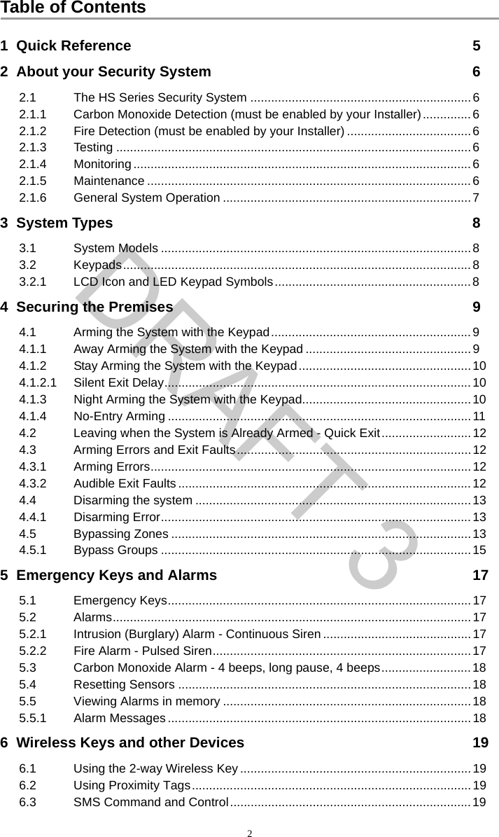
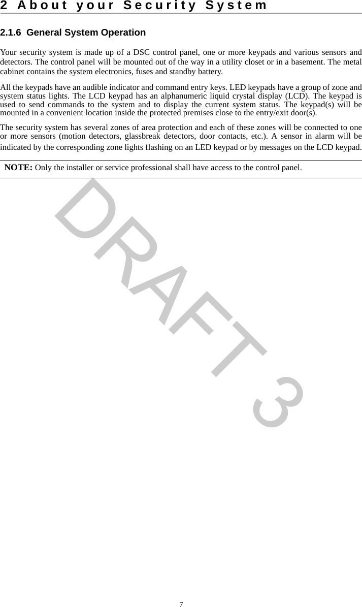
![51 Quick ReferenceThe HS Series Alarm System uses a menu based navigation system. The scroll keys are used to cycle through the list of actions contained within the current menu. However, many actions can also be accessed using a shortcut key. If an action can be accessed using a shortcut key, the key will be listed in the instructions below. If you see [Scroll] use the keys to cycle to the listed menu item. Lookup detailed information on any of the listed actions using the accompanying Section number. NOTE: Some features must be enabled by installer.Status LightsReady - Indicates system normal. Must be on to arm system. All zones must be secured or bypassed and the system disarmed for this light to activate.Armed- Indicates system is armed. If the Ready light and the Armed light are both on it indicates an Exit Delay is in progress.Trouble - On indicates a system malfunction or tamper. Flashing indicates that the keypad has a low battery condition. Follow the instructions displayed or enter [*][2] to view trouble. Correcting the trouble turns of the indicator.AC Power - Indicates AC Power is present. The AC Power light will turn off when AC is absent.Action Press SectionArming and DisarmingAway Arm for 2 seconds 4.1.1Stay Arm for 2 seconds 4.1.2Night Arm + [Access Code] 4.1.3Disarm [Access Code] 4.4No-Entry Arming + [Access Code] 4.1.4Quick Arm/Quick Exit 4.1.1Bypass Zone + [Access Code] + [3 Digit Zone #] + 4.5 BypassingRecall Last Bypass + [Access Code] + [Scroll] Bypass Options + 4.5Clear Bypass + [Access Code] + [Scroll] Bypass Options + + [Scroll] Clear Bypasses + 4.5Load Bypass Group + [Access Code] + [Scroll] Bypass Options + + [Scroll] Bypass Group + 4.5.1Common FunctionsSelect Language for 2 seconds 8.1Set Time and Date [Master Code] + 8.3.2Turn Chime ON/OFF 8.2Change Brightness [Master Code] + 8.3.8Change Contrast [Master Code] + 8.3.9Add/delete user + [Access Code] + [Scroll] Access Code + 7.1.1Reset Sensors 5.4View Troubles 9.1View Alarms 5.5Perform System Test [Master Code] + 11.1Buzzer Volume [Master Code] + 8.3.10***9*0****************601*4*612*613*5**2*3*604*615DRAFT 3](https://usermanual.wiki/Tyco-Safety-Canada/13HS2KRFP9/User-Guide-1973259-Page-5.png)
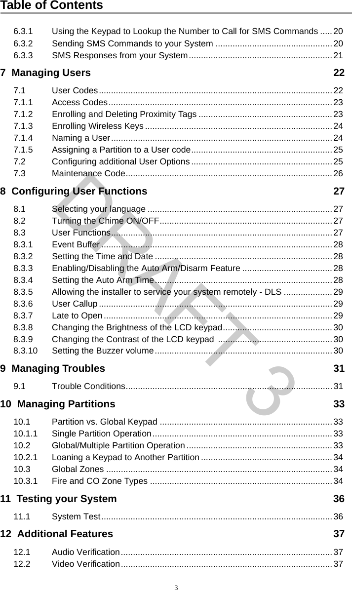
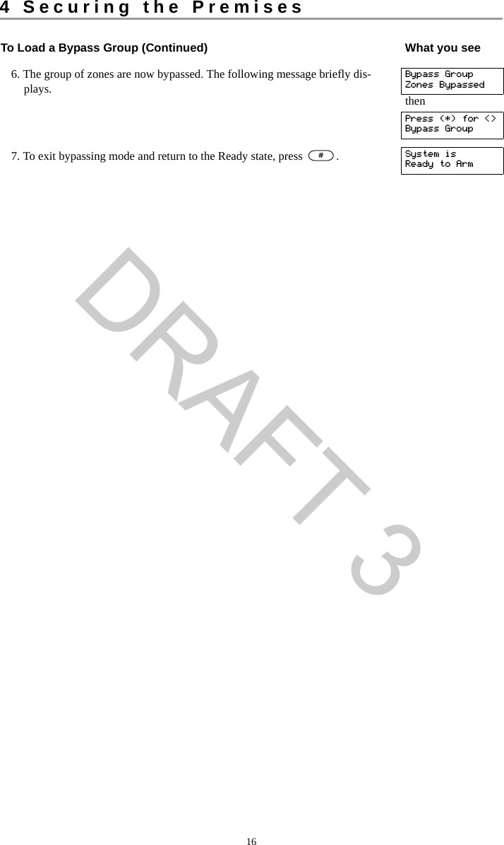
![83 System Types3.1 System Models3.2 KeypadsThe HS Series Alarm System supports a variety wireless, hardwired and proximity sensor LCD, LED and Icon keypads. 3.2.1 LCD Icon and LED Keypad SymbolsHS2016 16 Zone Alarm SystemHS2016-4 16 Zone Alarm SystemHS2032 32 Zone Alarm SystemHS2064 64 Zone Alarm SystemHS2128 128 Zone Alarm System1 Clock Digits 1, 2 These two 7 segment clock digits indicate the hour digits when the local clock is active, and identify the zone when the OPEN or ALARM icons are active. These two digits scroll one zone per second from the lowest zone number to the highest when scrolling through zones.2 : (Colon) This icon is the hours/minutes divider and will flash once a second when the local clock is active. 3 Clock Digits 3, 4 These two 7 segment displays are the minute digits when the local clock is active.41 to 8 These numbers identify troubles when [Q][2] is pressed. 5Memory Indicates that there are alarms in memory. 6 Bypass Indicates that there are zones automatically or manually bypassed.7 Program Indicates that the system is in Installer’s Programming, or the keypad is busy. 8Away Indicates that the panel is armed in the Away Mode. 9Fire Indicates that there are fire alarms in memory.10 Stay Indicates that the panel is armed in the Stay Mode. 11 Chime This icon turns on when the Chime function key is pressed to enable Door Chime on the system. It will turn off when the chime function key is pressed again to disable Door Chime.12 OPEN This icon is used with clock digits 1 and 2 to indicate violated zones (not alarm) on the system. When zones are opened, the OPEN icon will turn on, and 7 segment dis-plays 1 and 2 will scroll through the violated zones.13 AC Indicates that AC is present at the main panel.14 System Trouble Indicates that a system trouble is active.15 Night Indicates that the panel is armed in the Night Mode.16 Ready Light (green) If the Ready light is on, the system is ready for arming.17 Armed Light (red) If the Armed light is on, the system has been armed successfully.59612 710111815234171614135976HS2ICN Series HS2LED SeriesDRAFT 3](https://usermanual.wiki/Tyco-Safety-Canada/13HS2KRFP9/User-Guide-1973259-Page-8.png)
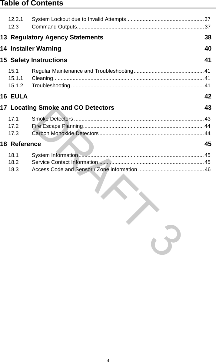
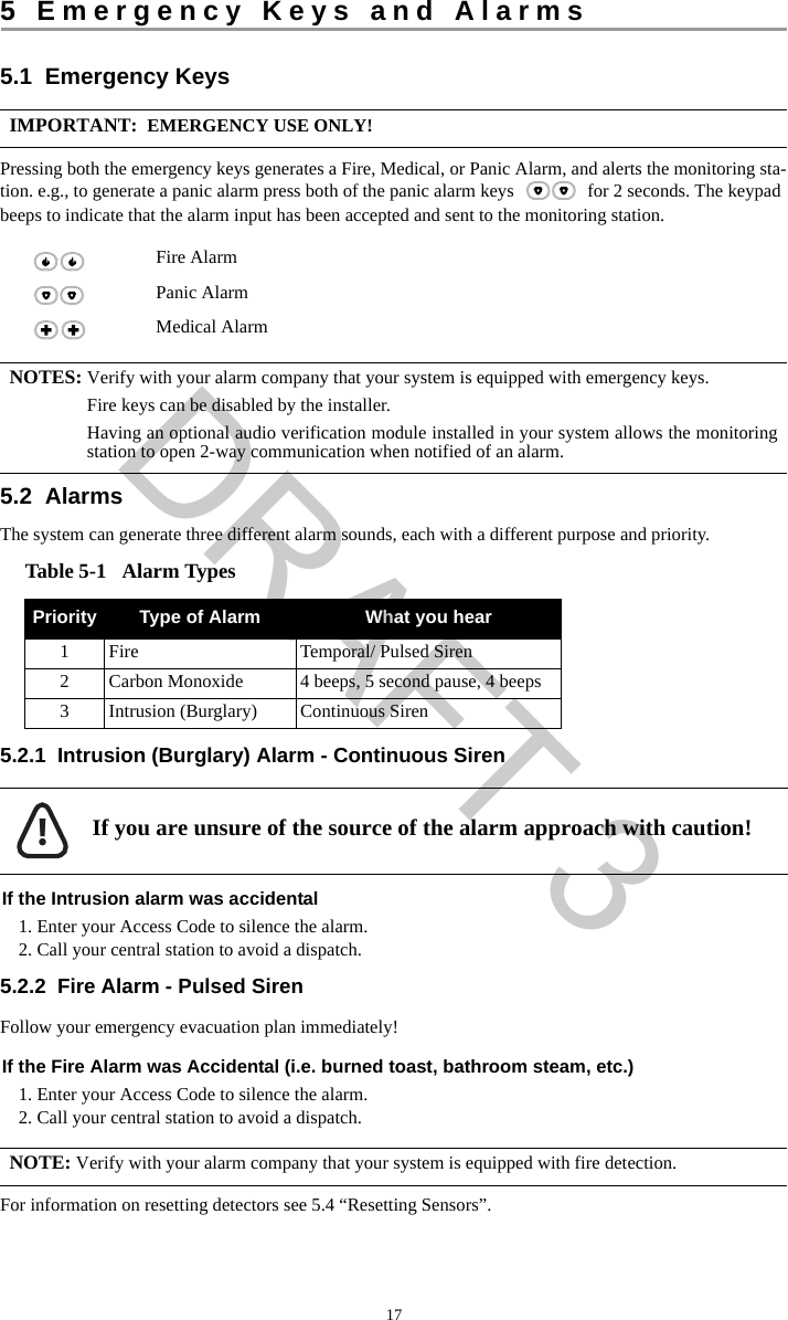
![94 Securing the Premises4.1 Arming the System with the KeypadThe HS Series provides multiple arming modes as described below:4.1.1 Away Arming the System with the KeypadAway mode activates the complete alarm system by: • Arming all perimeter sensors.• Arming all interior sensors.Away mode Use when all members of your household will not be home. Away mode activates all perimeter and interior sensors in the alarm system. Stay mode Use this mode when you are staying home, but expect someone to use the entrance door later. Stay mode partially activates your alarm system by arming all perimeter sensors and bypassing all interior sensors.Night mode Use when you want the perimeter and interior armed but would like to allow limited movement in your house without activating the alarm. e.g., disable motion sensors in an area containing bedrooms and a washroom. Night mode is similar to Stay mode but only bypasses internal sensors configured as Night Zones. NOTES: Verify with your alarm company which modes are available on your system.For SIA FAR listed panels, the Stay Arming Exit Delay will be twice as long as the AwayArming Exit Delay.To Arm the System in Away Mode What you see1. Ensure all windows and doors are closed and that the Ready indicator is on. Date TimeJAN 02/13 2:06a2. To arm using the Away key press and hold the Away key for 2 seconds and if required enter your [access code].ORTo Quick Arm the system press . System is Ready to ArmthenEnter YourAccess Code3. If zones have been bypassed a warning appears. * Warning *Bypass Active4. After successfully initiating the arming sequence the:• Armed indicator turns on.• Ready indicator remains lit.• Exit Delay timer begins counting down.• Keypad beeps six times, continues beeping once per second until beeping rapidly in the final ten seconds. Exit Delay in ProgressYou now have ____ seconds to leave the premises. 5. To cancel the arming sequence, enter your [access code]. System DisarmedNo Alarm Memory6. Once the exit delay timer expires thereby arming the system the: • Ready indicator turns off.• Armed indicator remains on.• Keypad stops sounding.System Armedin Away ModeNOTE: The installer configures the exit delay timer and whether or not an access code is required for arming the system. *0DRAFT 3](https://usermanual.wiki/Tyco-Safety-Canada/13HS2KRFP9/User-Guide-1973259-Page-9.png)
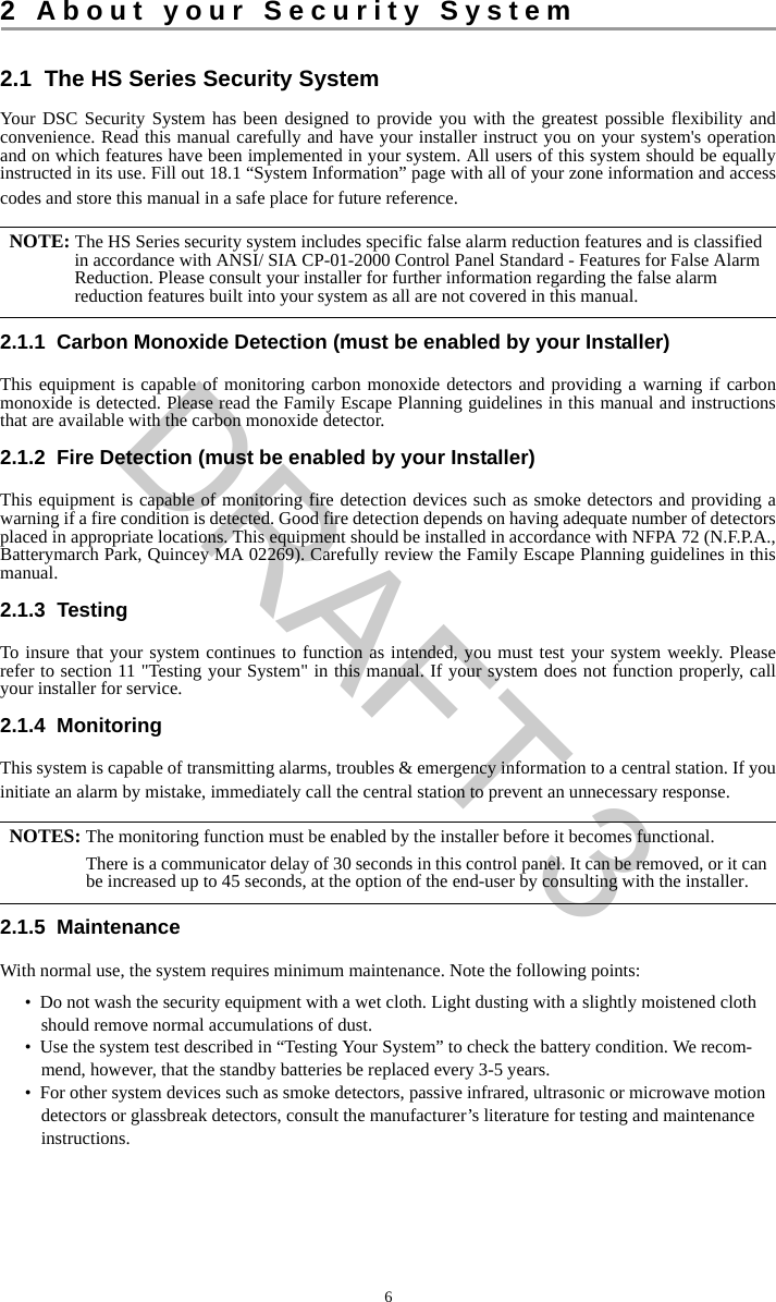
![4 Securing the Premises104.1.2 Stay Arming the System with the KeypadStay mode partially activates your alarm system by:• Arming all perimeter sensors. • Bypassing all interior sensors. 4.1.2.1 Silent Exit DelayIf the system is armed using the Stay key or the No Entry Arming method :• The warning beep is silenced.• The exit time is doubled for that exit period only (CP-01 versions only). 4.1.3 Night Arming the System with the KeypadNight mode partially activates the alarm system by:• Bypassing all internal sensors configured as Night zones.• Arming all perimeter sensors. • Arming all other internal sensors.Arming the system in Night mode is only possible after the system has first been armed in Stay mode. To access armed interior areas when the system is armed in Night Mode you must disarm the system.To Arm the System in Stay mode What you see1. Ensure all windows and doors are closed and that the Ready indicator is on. Date TimeJAN 02/13 2:06a2. Press and hold the Stay key for 2 seconds and if required enter your [access code]. Do not leave the premises. System is Ready to ArmthenEnter YourAccess Code3. If zones have been bypassed a warning appears. * Warning *Bypass Active4. After successfully initiating the arming sequence the:• Armed indicator turns on.• Ready indicator remains lit.• Exit Delay timer begins counting down.Exit Delay in Progress5. To cancel the arming sequence, enter your [access code]. System DisarmedNo Alarm Memory6. Once the exit delay timer expires thereby arming the system the: • Ready indicator turns off.• Armed indicator remains on.• Bypass or system indicator activates.System Armedin Stay ModeNOTE: For non CP-01 versions, Standard Exit Time is used. NOTE: Ensure that your installer has provided you with a list identifying all programmed night zones.*9DRAFT 3](https://usermanual.wiki/Tyco-Safety-Canada/13HS2KRFP9/User-Guide-1973259-Page-10.png)
![4 Securing the Premises114.1.4 No-Entry ArmingNo-Entry Arming arms the system in Stay mode by:• Removing the Entry Delay from all configured zones. • Arming all perimeter sensors. • Bypassing all interior sensors.An entry through any zone will create an instant alarm.To Arm the System in Night mode What you see1. Once the system is armed in Stay mode (Armed indicator is on) at any key-pad press ORpress . Date TimeJAN 02/13 2:06athenPress (*) for <>Interior Arm2. If required enter your [access code]. All interior zones will now be armed except for devices programmed as Night Zones. The Night mode icon turns on.Enter YourAccess CodethenInterior HasBeen ArmedTo gain access to interior areas that are armed during Night mode• Disarm the system by entering your [access code].To No-Entry Arm the System What you see1. Check that the Ready indicator is on and your system is ready to be armed. Date TimeJAN 02/13 2:06a2. Press and enter your [access code]. Enter YourAccess Code3. If zones have been bypassed a warning appears. * Warning *Bypass Activethen4. After successfully initiating the arming sequence the:• Armed light flashes as a reminder that the system is armed and has no entry delay.• Keypad sounds fast beeps.• Keypad displays “Exit Delay in Progress”.Armed With NoEntry DelaythenExit Delay inProgress5. To cancel the arming sequence, enter your [access code]. System DisarmedNo Alarm Memory6. Once the exit delay timer expires the system is armed. System Armedin Stay Mode***1*9DRAFT 3](https://usermanual.wiki/Tyco-Safety-Canada/13HS2KRFP9/User-Guide-1973259-Page-11.png)
![4 Securing the Premises124.2 Leaving when the System is Already Armed - Quick ExitUse the Quick Exit feature if the system is already armed and you would like to leave without disarming and rearming the system. Quick Exit uses the same hot keys as Quick Arming, and it provides you with a two minute exit delay to leave the premises without triggering an alarm. Once the door you leave from closes, any time remaining on the 2 minute exit delay will be cancelled. 4.3 Arming Errors and Exit FaultsThe HS Series audibly notifies you of any errors when you are attempting to arm the system or exit the premises. 4.3.1 Arming ErrorsAn error tone sounds if the system is unable to arm. Arming errors occur if:• The system is not ready to arm (i.e., sensors are open).• An incorrect user code is entered. 4.3.2 Audible Exit FaultsIn an attempt to reduce false alarms, the Audible Exit Fault notifies you of an improper exit when arming the system in the Away mode. Improper exits are caused by:• Failing to exit the premises during the exit delay period.• Failing to securely close the Exit/Entry door.Improper exits cause the following system notifications: • The keypad emits one continuous beep.• The bell or siren sounds. To Quick Exit What you see1. When the system is already armed and the Armed light is lit, press and hold the Quick Exit key for 2 secondsOR press .Quick Exit inProgress2. Exit the premises within 2 minutes.To Correct an Arming Error1. Ensure all sensors are secure.2. Press and try arming the system again. For details on arming the system, see one of the previ-ous arming procedures.3. If errors persist contact your installer.NOTE: Must be enabled by installer. To Correct an Exit Fault1. Re-enter the premises.2. Disarm the system before the entry delay timer expires by entering your [access code].3. Follow the Away arming procedure again, making sure to close the entry/exit door properly. For more details see 4.1.1 “Away Arming the System with the Keypad”.*0*DRAFT 3](https://usermanual.wiki/Tyco-Safety-Canada/13HS2KRFP9/User-Guide-1973259-Page-12.png)
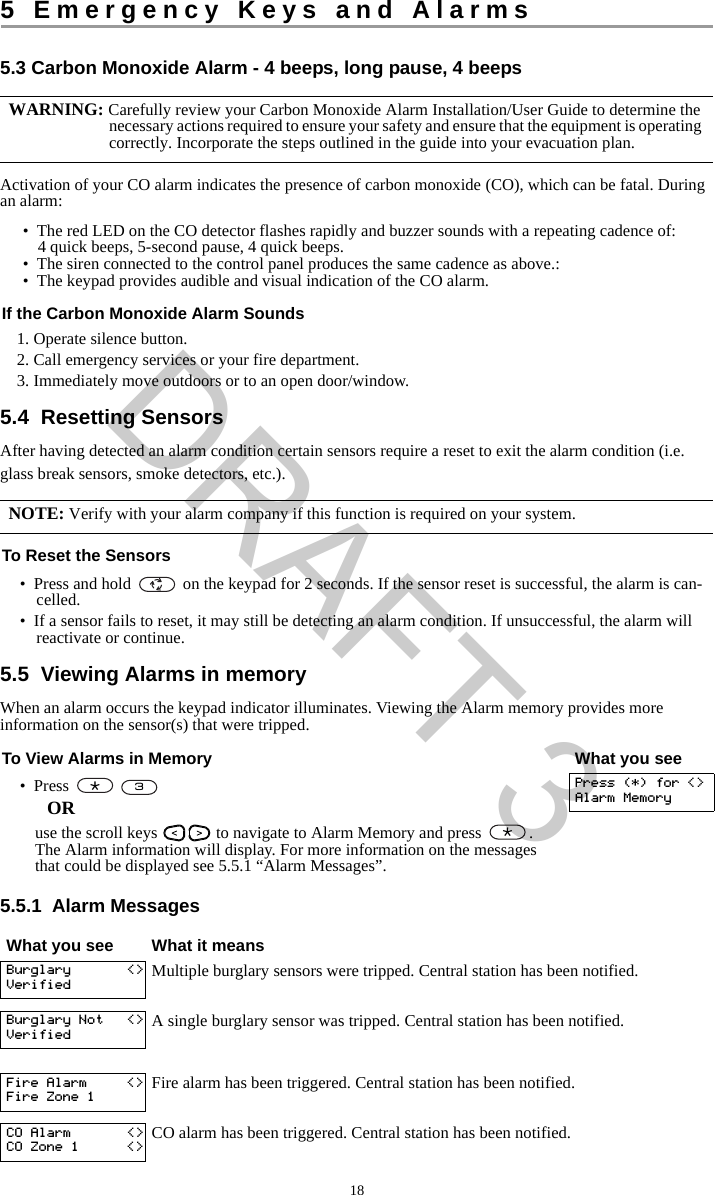
![4 Securing the Premises134.4 Disarming the systemDepending on your system configuration, there are multiple methods you can use to disarm your system.You can disarm the system using a:• Keypad• 2-way wireless key• Proximity Tag4.4.1 Disarming ErrorIf your code is invalid, the system will not disarm and a 2-second error tone will sound. If this occurs, re-enter your access code.4.5 Bypassing ZonesBypassing zones intentionally unprotects specified zones the next time your system is armed. Bypassed zones are flagged on the LCD screen. For more information on zone flags see Table 4-1. Bypassed zones:• Must be configured before arming the system. • Can be done using a keypad or SMS.• Allow for access to protected areas when the system is armed.• Allow you to arm the system if a zone is temporarily out of service.• Reduce the level of security.• Will not sound an alarm.• Are automatically cancelled each time the system is disarmed.• Can be programmed together within bypass groups. For more information see 4.5.1 “Bypass Groups”. To Disarm the System with a Keypad• Enter your [access code] anytime the system is armed. (Armed indicator is on). • If you walk through the entry door the keypad will beep. Enter your code within _____ seconds to avoid an alarm condition.NOTE: Duration of Entry timer is programmed by installer.WARNING:If a zone is not operating properly contact a service technician immediately.Table 4-1 Zone FlagsLCD Display Flag DescriptionZone Label <> none Zone is ready for arming.Zone Label <> O O Zone is currently open. You may be unable to arm the system.Zone Label <> B B Zone is bypassed. NOTES: Ensure that no zones are unintentionally bypassed when arming your system.24-hour zones can only be unbypassed manually. For security reasons, your installer has programmed the system to prevent you from bypassingcertain zones (e.g., smoke detectors). For more information on fire zones see 10.3.1 “Fire andCO Zone Types”.DRAFT 3](https://usermanual.wiki/Tyco-Safety-Canada/13HS2KRFP9/User-Guide-1973259-Page-13.png)
![4 Securing the Premises14Additional bypass features:Recall Last Bypass Recalls all zones that were bypassed the last time the bypass zone feature was used.Clear Bypass Instantly clears all zones flagged to be bypassed.Programming a Bypass Group Use when you consistently bypass the same zones. This feature allows you to store one group of bypassed zones in memory.Activating a Bypass Group Loads a stored bypass group from memory.To Bypass Zones What you see1. Check that the Ready indicator is on and the system is disarmed. Date TimeJAN 02/13 2:06a2. Press to enter the function menu. Press (*) for <>Zone Bypass3. Press or . If required enter your [access code]. Scroll to <>Bypass Zones4. Scroll to the desired zone using the keys.ORDirectly bypass zones by entering their 3 digit zone number.Zone 1 <>5. Press to toggle a bypass of the zone. To unbypass a zone press again. To bypass more zones repeat step 4.Zone Label <> B6. When arming the system the following message briefly displays. * Warning *Bypass Active7. To exit bypassing mode and return to the Ready state, press .To Recall the Last Bypassed Zones What you see1. Check that the Ready indicator is on and the system is disarmed. Date TimeJAN 02/13 2:06a2. Press to enter the function menu. Press (*) for <>Zone Bypass3. Press or . If required enter your [access code]. Scroll to <>Bypass Zones4. Scroll to the Bypass Options menu using the keys. Press (*) for <>Bypass Options5. Press to enter the Bypass Options menu. Press (*) for <>Bypass Recall6. Press to recall the last bypassed zone(s). These zone(s) will be bypassed the next time the system is armed.Bypass RecalledZones Bypassed7. To exit bypassing mode and return to the Ready state, press . System isReady to ArmTo Clear the Bypass Flag from All Zones What you see1. Check that the Ready indicator is on and the system is disarmed. Date TimeJAN 02/13 2:06a2. Press to enter the function menu. Press (*) for <>Zone Bypass**1*****1****DRAFT 3](https://usermanual.wiki/Tyco-Safety-Canada/13HS2KRFP9/User-Guide-1973259-Page-14.png)
![4 Securing the Premises154.5.1 Bypass GroupsProgram frequently bypassed zones into the system as a bypass group. Using bypass groups avoids individually bypassing each zone. One bypass group can be programmed per partition.3. Press or . If required enter your [access code]. Scroll to <>Bypass Zones4. Scroll to the Bypass Options menu using the keys. Press (*) for <>Bypass Options5. Press to enter the Bypass Options menu and scroll to Clear Bypasses. Press (*) for <>Clear Bypasses6. Press to clear all bypass flags. Bypass ClearedZones Unbypassed7. To exit bypassing mode and return to the Ready state, press . System isReady to ArmNOTE: This feature is not to be used in UL listed installations.To Program a Bypass Group What you see1. Check that the Ready indicator is on and the system is disarmed. Date TimeJAN 02/13 2:06a2. Press to enter the function menu. Press (*) for <>Zone Bypass3. Press or . If required enter your [access code]. Scroll to <>Bypass Zones4. Scroll to and flag all zones you want bypassed. Upstrs H Wdw <> B5. Once all zones to be bypassed are flagged, scroll to the Bypass Options menu and press .Press (*) for <>Bypass Options6. Scroll to Prg Bypass and press . Press (*) for <>Prg Bypass 7. The Bypass Group is now programmed. The keypad will beep three times. There will be no visual confirmation message.Press (*) for <>Zone Bypass8. To exit bypassing mode and return to the Ready state, press . System isReady to ArmTo Load a Bypass Group What you see1. Check that the Ready indicator is on and the system is disarmed. Date TimeJAN 02/13 2:06a2. Press to enter the function menu. Press (*) for <>Zone Bypass3. Press or . If required enter your [access code]. Scroll to <>Bypass Zones4. Scroll to the Bypass Options menu and press . Press (*) for <>Bypass Options5. Scroll to Bypass Group and press . Press (*) for <>Bypass Group To Clear the Bypass Flag from All Zones (Continued) What you see*1*****1**#**1**DRAFT 3](https://usermanual.wiki/Tyco-Safety-Canada/13HS2KRFP9/User-Guide-1973259-Page-15.png)
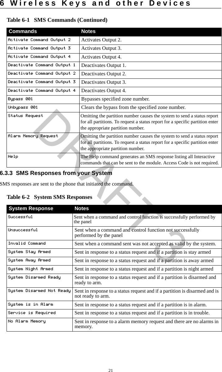
![6 Wireless Keys and other Devices206.3.1 Using the Keypad to Lookup the Number to Call for SMS CommandsThe phone number of the system is programmed by the installer. To quickly find the phone number perform the following steps.6.3.2 Sending SMS Commands to your SystemIn order to successfully send commands to your system from your cellphone, you must send SMS messages in the proper format. If configured, commands require the inclusion of a User Access Code in your message. The access code will be verified by the system before executing any commands.Additional information about sending SMS commands:• Text messages are not case sensitive and extra spaces are ignored. • In multi-partition systems and if the User has rights to manage the desired partitions, commands can be sent to specific partitions by including the partition number. For more information on partitions see section 10 "Managing Partitions".• If the panel is configured to require an Access Code and the code is not sent or is invalid, the panel will send a notification to the user advising the command was unsuccessful.Table 6-1 lists all available SMS commands with examples of how to enter the Partition number and access codes. The format for entering commands is as follows:To find the System’s Phone Number What you see1. Check that the Ready indicator is on and the system is disarmed. Date TimeJAN 02/13 2:06a2. Press ORpress and use the scroll keys to navigate to User Functions and press . If required enter your [access code].Press (*) for <>User Functions3. Press or use the scroll keys to navigate to SMS Pro-gramming and press Press (*) for <>SMS Programming4. Scroll to navigate to SMS Programming and press . The phone number to send your SMS commands to displays.Press (*) for <>GSM Phone No.Command Partition number Access CodeStay Arm 001 1234 NOTES: Verify with your installer that the Partition number and access code are required in your SMSmessage. If one or both are not required, do not enter them in your SMS message. Responses to Status and Alarm Memory requests may require more than 1 SMS message,depending on status of the system. There is a 10 second delay between transmission of SMSmessages.Table 6-1 SMS CommandsCommands NotesStay Arm Stay arms the system.Away Arm Away arms the system.Night Arm Night arms the system.Disarm Disarms the system.Activate Command Output 1 Activates Output 1.*6**1 1**DRAFT 3](https://usermanual.wiki/Tyco-Safety-Canada/13HS2KRFP9/User-Guide-1973259-Page-20.png)
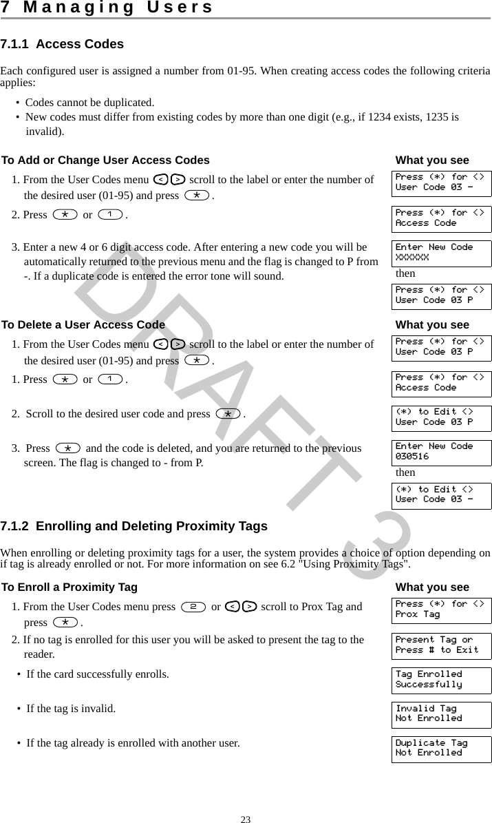
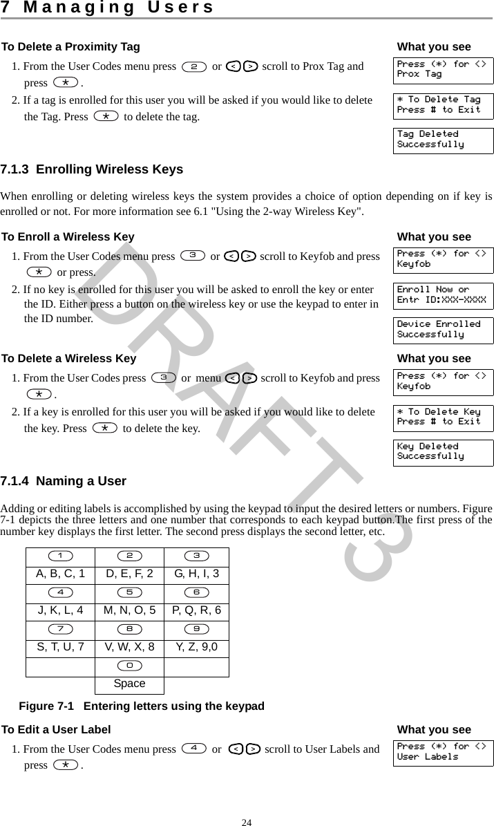
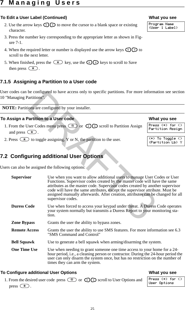
![227 Managing Users7.1 User CodesUp to 95 different users can be programmed in the HS Series. Each user can be:• Uniquely labeled.• Assigned an access code. • Assigned a proximity tag and/or wireless key (key fob). In order to operate, proximity tags and wire-less keys must be enrolled in the system.• Assigned to only operate specific partitions. For more information on partitions see section 10 "Man-aging Partitions".• Configured with additional attributes. For more information see 7.2 "Configuring additional User Options".Programed zones are flagged in the LCD screen. For more information on user flags see Table 7-1.NOTE: Your installer configures all access codes to be either 4 or 6 digits. You cannot have access codes of both lengths on your system. Table 7-1 User FlagsLCD Display Flag DescriptionUser Code 01 - - Unprogrammed code.User Code 01 P P Programmed code.User Code 01 T T Code and tag/key are programmed. To Access the User Codes Menu What you see1. Press OR press and use the scroll keys to navigate to User Codes and press .Press (*) for <>User Functions2. Enter [Master or supervisor code] and scroll through the list of Users. To edit a desired user press .Enter MasterAccess CodethenPress (*) for <>{User Label}3. To go back to the Ready state press .*5***#DRAFT 3](https://usermanual.wiki/Tyco-Safety-Canada/13HS2KRFP9/User-Guide-1973259-Page-22.png)