Tyco Safety Canada 13HS2KRFP9 Keypad with PowerG wireless receiver and prox User Manual 29008365R001 HS016 32 64 128 1 0 Book
Digital Security Controls Ltd. Keypad with PowerG wireless receiver and prox 29008365R001 HS016 32 64 128 1 0 Book
Users Manual
HS2016/2032/2064/2128 Alarm Panel
V1.0 User Manual
WARNING: This manual contains information on limitations regarding
product use and function and information on the limitations as to liability
of the manufacturer. The entire manual should be carefully read.
DRAFT 3

Table of Contents
2
1 Quick Reference 5
2 About your Security System 6
2.1 The HS Series Security System ................................................................6
2.1.1 Carbon Monoxide Detection (must be enabled by your Installer)..............6
2.1.2 Fire Detection (must be enabled by your Installer) ....................................6
2.1.3 Testing .......................................................................................................6
2.1.4 Monitoring .................................................................................................. 6
2.1.5 Maintenance ..............................................................................................6
2.1.6 General System Operation ........................................................................7
3 System Types 8
3.1 System Models ..........................................................................................8
3.2 Keypads.....................................................................................................8
3.2.1 LCD Icon and LED Keypad Symbols.........................................................8
4 Securing the Premises 9
4.1 Arming the System with the Keypad.......................................................... 9
4.1.1 Away Arming the System with the Keypad ................................................9
4.1.2 Stay Arming the System with the Keypad..................................................10
4.1.2.1 Silent Exit Delay......................................................................................... 10
4.1.3 Night Arming the System with the Keypad.................................................10
4.1.4 No-Entry Arming ........................................................................................11
4.2 Leaving when the System is Already Armed - Quick Exit..........................12
4.3 Arming Errors and Exit Faults....................................................................12
4.3.1 Arming Errors............................................................................................. 12
4.3.2 Audible Exit Faults .....................................................................................12
4.4 Disarming the system ................................................................................13
4.4.1 Disarming Error..........................................................................................13
4.5 Bypassing Zones .......................................................................................13
4.5.1 Bypass Groups ..........................................................................................15
5 Emergency Keys and Alarms 17
5.1 Emergency Keys........................................................................................17
5.2 Alarms........................................................................................................17
5.2.1 Intrusion (Burglary) Alarm - Continuous Siren ...........................................17
5.2.2 Fire Alarm - Pulsed Siren...........................................................................17
5.3 Carbon Monoxide Alarm - 4 beeps, long pause, 4 beeps..........................18
5.4 Resetting Sensors ..................................................................................... 18
5.5 Viewing Alarms in memory ........................................................................18
5.5.1 Alarm Messages ........................................................................................18
6 Wireless Keys and other Devices 19
6.1 Using the 2-way Wireless Key ...................................................................19
6.2 Using Proximity Tags.................................................................................19
6.3 SMS Command and Control......................................................................19
DRAFT 3

Table of Contents
3
6.3.1 Using the Keypad to Lookup the Number to Call for SMS Commands .....20
6.3.2 Sending SMS Commands to your System ................................................20
6.3.3 SMS Responses from your System...........................................................21
7 Managing Users 22
7.1 User Codes................................................................................................22
7.1.1 Access Codes............................................................................................23
7.1.2 Enrolling and Deleting Proximity Tags .......................................................23
7.1.3 Enrolling Wireless Keys .............................................................................24
7.1.4 Naming a User...........................................................................................24
7.1.5 Assigning a Partition to a User code..........................................................25
7.2 Configuring additional User Options ..........................................................25
7.3 Maintenance Code.....................................................................................26
8 Configuring User Functions 27
8.1 Selecting your language ............................................................................27
8.2 Turning the Chime ON/OFF.......................................................................27
8.3 User Functions...........................................................................................27
8.3.1 Event Buffer ...............................................................................................28
8.3.2 Setting the Time and Date ......................................................................... 28
8.3.3 Enabling/Disabling the Auto Arm/Disarm Feature .....................................28
8.3.4 Setting the Auto Arm Time.........................................................................28
8.3.5 Allowing the installer to service your system remotely - DLS ....................29
8.3.6 User Callup ................................................................................................29
8.3.7 Late to Open ..............................................................................................29
8.3.8 Changing the Brightness of the LCD keypad.............................................30
8.3.9 Changing the Contrast of the LCD keypad ...............................................30
8.3.10 Setting the Buzzer volume.........................................................................30
9 Managing Troubles 31
9.1 Trouble Conditions.....................................................................................31
10 Managing Partitions 33
10.1 Partition vs. Global Keypad .......................................................................33
10.1.1 Single Partition Operation..........................................................................33
10.2 Global/Multiple Partition Operation ............................................................33
10.2.1 Loaning a Keypad to Another Partition ......................................................34
10.3 Global Zones ............................................................................................. 34
10.3.1 Fire and CO Zone Types ...........................................................................34
11 Testing your System 36
11.1 System Test...............................................................................................36
12 Additional Features 37
12.1 Audio Verification.......................................................................................37
12.2 Video Verification.......................................................................................37
DRAFT 3

Table of Contents
4
12.2.1 System Lockout due to Invalid Attempts....................................................37
12.3 Command Outputs.....................................................................................37
13 Regulatory Agency Statements 38
14 Installer Warning 40
15 Safety Instructions 41
15.1 Regular Maintenance and Troubleshooting...............................................41
15.1.1 Cleaning.....................................................................................................41
15.1.2 Troubleshooting .........................................................................................41
16 EULA 42
17 Locating Smoke and CO Detectors 43
17.1 Smoke Detectors .......................................................................................43
17.2 Fire Escape Planning.................................................................................44
17.3 Carbon Monoxide Detectors......................................................................44
18 Reference 45
18.1 System Information....................................................................................45
18.2 Service Contact Information ......................................................................45
18.3 Access Code and Sensor / Zone information ............................................46
DRAFT 3
5
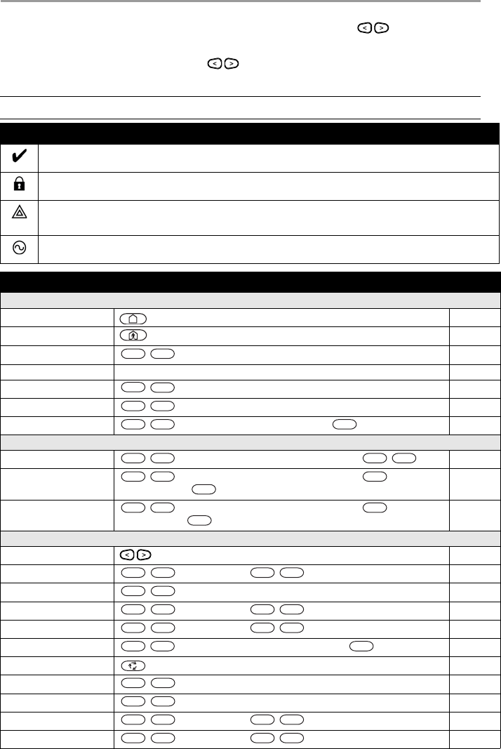
1 Quick Reference
The HS Series Alarm System uses a menu based navigation system. The scroll keys are used to
cycle through the list of actions contained within the current menu. However, many actions can also be
accessed using a shortcut key. If an action can be accessed using a shortcut key, the key will be listed in the
instructions below. If you see [Scroll] use the keys to cycle to the listed menu item. Lookup
detailed information on any of the listed actions using the accompanying Section number.
NOTE: Some features must be enabled by installer.
Status Lights
Ready - Indicates system normal. Must be on to arm system. All zones must be secured or bypassed and the system
disarmed for this light to activate.
Armed- Indicates system is armed. If the Ready light and the Armed light are both on it indicates an Exit Delay is in
progress.
Trouble - On indicates a system malfunction or tamper. Flashing indicates that the keypad has a low battery
condition. Follow the instructions displayed or enter [*][2] to view trouble. Correcting the trouble turns of the
indicator.
AC Power - Indicates AC Power is present. The AC Power light will turn off when AC is absent.
Action Press Section
Arming and Disarming
Away Arm for 2 seconds 4.1.1
Stay Arm for 2 seconds 4.1.2
Night Arm + [Access Code] 4.1.3
Disarm [Access Code] 4.4
No-Entry Arming + [Access Code] 4.1.4
Quick Arm/Quick Exit 4.1.1
Bypass Zone + [Access Code] + [3 Digit Zone #] + 4.5
Bypassing
Recall Last Bypass + [Access Code] + [Scroll] Bypass Options + 4.5
Clear Bypass + [Access Code] + [Scroll] Bypass Options + + [Scroll]
Clear Bypasses +
4.5
Load Bypass Group + [Access Code] + [Scroll] Bypass Options + + [Scroll]
Bypass Group +
4.5.1
Common Functions
Select Language for 2 seconds 8.1
Set Time and Date [Master Code] + 8.3.2
Turn Chime ON/OFF 8.2
Change Brightness [Master Code] + 8.3.8
Change Contrast [Master Code] + 8.3.9
Add/delete user + [Access Code] + [Scroll] Access Code + 7.1.1
Reset Sensors 5.4
View Troubles 9.1
View Alarms 5.5
Perform System Test [Master Code] + 11.1
Buzzer Volume [Master Code] + 8.3.10
*
*
*
9
*
0
*
*
*
*
*
*
*
*
*
*
*
*
*
*
*
*
6
0
1
*
4
*
6
1
2
*
6
1
3
*
5
*
*
2
*
3
*
6
0
4
*
6
1
5
DRAFT 3

6
2 About your Security System
2.1 The HS Series Security System
Your DSC Security System has been designed to provide you with the greatest possible flexibility and
convenience. Read this manual carefully and have your installer instruct you on your system's operation
and on which features have been implemented in your system. All users of this system should be equally
instructed in its use. Fill out 18.1 “System Information” page with all of your zone information and access
codes and store this manual in a safe place for future reference.
2.1.1 Carbon Monoxide Detection (must be enabled by your Installer)
This equipment is capable of monitoring carbon monoxide detectors and providing a warning if carbon
monoxide is detected. Please read the Family Escape Planning guidelines in this manual and instructions
that are available with the carbon monoxide detector.
2.1.2 Fire Detection (must be enabled by your Installer)
This equipment is capable of monitoring fire detection devices such as smoke detectors and providing a
warning if a fire condition is detected. Good fire detection depends on having adequate number of detectors
placed in appropriate locations. This equipment should be installed in accordance with NFPA 72 (N.F.P.A.,
Batterymarch Park, Quincey MA 02269). Carefully review the Family Escape Planning guidelines in this
manual.
2.1.3 Testing
To insure that your system continues to function as intended, you must test your system weekly. Please
refer to section 11 "Testing your System" in this manual. If your system does not function properly, call
your installer for service.
2.1.4 Monitoring
This system is capable of transmitting alarms, troubles & emergency information to a central station. If you
initiate an alarm by mistake, immediately call the central station to prevent an unnecessary response.
2.1.5 Maintenance
With normal use, the system requires minimum maintenance. Note the following points:
• Do not wash the security equipment with a wet cloth. Light dusting with a slightly moistened cloth
should remove normal accumulations of dust.
• Use the system test described in “Testing Your System” to check the battery condition. We recom-
mend, however, that the standby batteries be replaced every 3-5 years.
• For other system devices such as smoke detectors, passive infrared, ultrasonic or microwave motion
detectors or glassbreak detectors, consult the manufacturer’s literature for testing and maintenance
instructions.
NOTE: The HS Series security system includes specific false alarm reduction features and is classified
in accordance with ANSI/ SIA CP-01-2000 Control Panel Standard - Features for False Alarm
Reduction. Please consult your installer for further information regarding the false alarm
reduction features built into your system as all are not covered in this manual.
NOTES: The monitoring function must be enabled by the installer before it becomes functional.
There is a communicator delay of 30 seconds in this control panel. It can be removed, or it can
be increased up to 45 seconds, at the option of the end-user by consulting with the installer.
DRAFT 3

2 About your Security System
7
2.1.6 General System Operation
Your security system is made up of a DSC control panel, one or more keypads and various sensors and
detectors. The control panel will be mounted out of the way in a utility closet or in a basement. The metal
cabinet contains the system electronics, fuses and standby battery.
All the keypads have an audible indicator and command entry keys. LED keypads have a group of zone and
system status lights. The LCD keypad has an alphanumeric liquid crystal display (LCD). The keypad is
used to send commands to the system and to display the current system status. The keypad(s) will be
mounted in a convenient location inside the protected premises close to the entry/exit door(s).
The security system has several zones of area protection and each of these zones will be connected to one
or more sensors (motion detectors, glassbreak detectors, door contacts, etc.). A sensor in alarm will be
indicated by the corresponding zone lights flashing on an LED keypad or by messages on the LCD keypad.
NOTE: Only the installer or service professional shall have access to the control panel.
DRAFT 3
8
3 System Types
3.1 System Models
3.2 Keypads
The HS Series Alarm System supports a variety wireless, hardwired and proximity sensor LCD, LED and
Icon keypads.
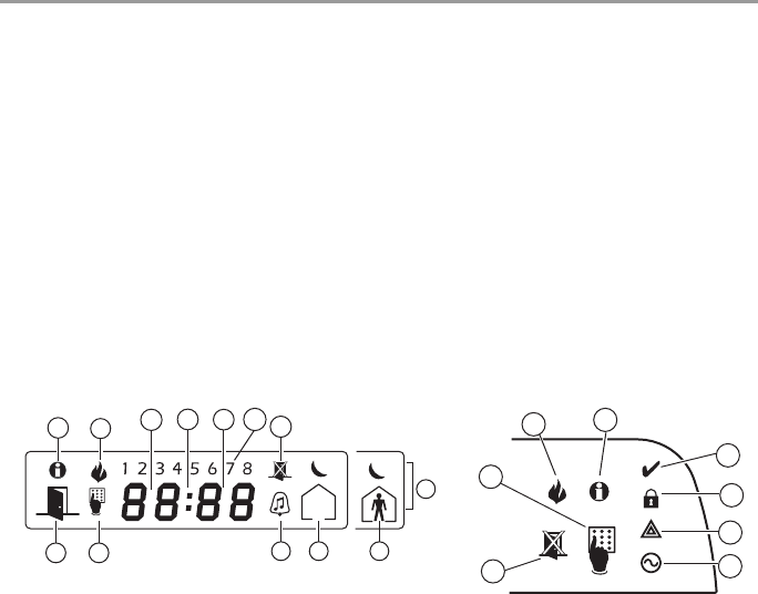
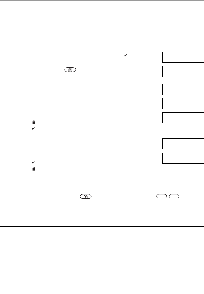
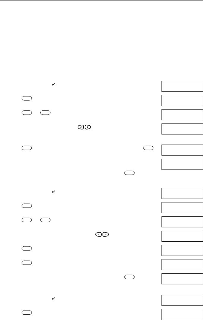
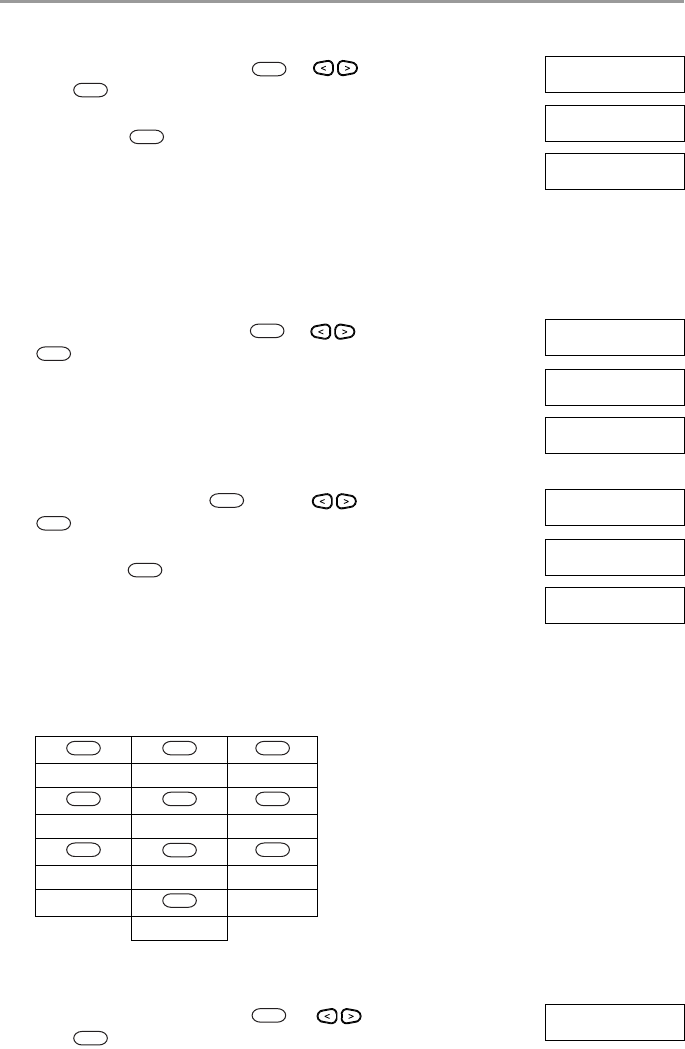
3.2.1 LCD Icon and LED Keypad Symbols
HS2016 16 Zone Alarm System
HS2016-4 16 Zone Alarm System
HS2032 32 Zone Alarm System
HS2064 64 Zone Alarm System
HS2128 128 Zone Alarm System
1 Clock Digits 1, 2 These two 7 segment clock digits indicate the hour digits when the local clock is
active, and identify the zone when the OPEN or ALARM icons are active. These two
digits scroll one zone per second from the lowest zone number to the highest when
scrolling through zones.
2 : (Colon) This icon is the hours/minutes divider and will flash once a second when the local
clock is active.
3 Clock Digits 3, 4 These two 7 segment displays are the minute digits when the local clock is active.
41 to 8 These numbers identify troubles when [Q][2] is pressed.
5Memory Indicates that there are alarms in memory.
6 Bypass Indicates that there are zones automatically or manually bypassed.
7 Program Indicates that the system is in Installer’s Programming, or the keypad is busy.
8Away Indicates that the panel is armed in the Away Mode.
9Fire Indicates that there are fire alarms in memory.
10 Stay Indicates that the panel is armed in the Stay Mode.
11 Chime This icon turns on when the Chime function key is pressed to enable Door Chime on
the system. It will turn off when the chime function key is pressed again to disable
Door Chime.
12 OPEN This icon is used with clock digits 1 and 2 to indicate violated zones (not alarm) on
the system. When zones are opened, the OPEN icon will turn on, and 7 segment dis-
plays 1 and 2 will scroll through the violated zones.
13 AC Indicates that AC is present at the main panel.
14 System Trouble Indicates that a system trouble is active.
15 Night Indicates that the panel is armed in the Night Mode.
16 Ready Light (green) If the Ready light is on, the system is ready for arming.
17 Armed Light (red) If the Armed light is on, the system has been armed successfully.
5
96
12 710
11
1
8
15
234
17
16
14
13
5
9
7
6
HS2ICN Series HS2LED Series
DRAFT 3
9
4 Securing the Premises
4.1 Arming the System with the Keypad
The HS Series provides multiple arming modes as described below:
4.1.1 Away Arming the System with the Keypad
Away mode activates the complete alarm system by:
• Arming all perimeter sensors.
• Arming all interior sensors.
Away mode Use when all members of your household will not be home. Away mode activates all
perimeter and interior sensors in the alarm system.
Stay mode Use this mode when you are staying home, but expect someone to use the entrance door
later. Stay mode partially activates your alarm system by arming all perimeter sensors and
bypassing all interior sensors.
Night mode Use when you want the perimeter and interior armed but would like to allow limited
movement in your house without activating the alarm. e.g., disable motion sensors in an
area containing bedrooms and a washroom. Night mode is similar to Stay mode but only
bypasses internal sensors configured as Night Zones.
NOTES: Verify with your alarm company which modes are available on your system.
For SIA FAR listed panels, the Stay Arming Exit Delay will be twice as long as the Away
Arming Exit Delay.
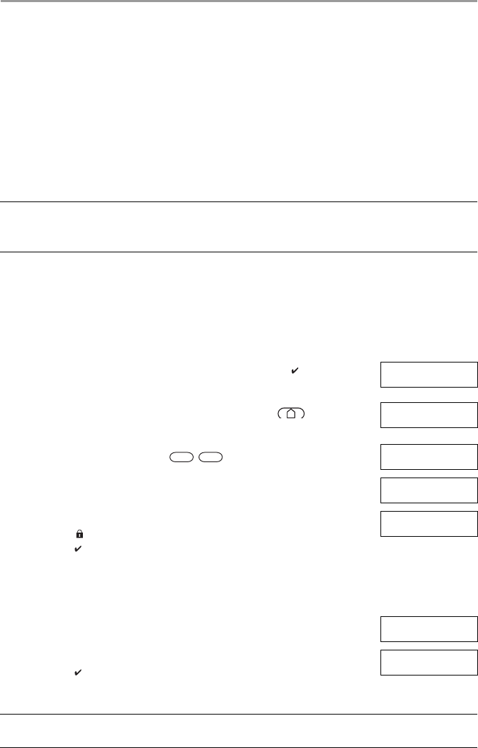
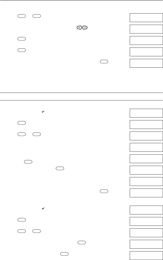
To Arm the System in Away Mode What you see
1. Ensure all windows and doors are closed and that the Ready indicator is on. Date Time
JAN 02/13 2:06a
2. To arm using the Away key press and hold the Away key for 2 seconds
and if required enter your [access code].
OR
To Quick Arm the system press .
System is
Ready to Arm
then
Enter Your
Access Code
3. If zones have been bypassed a warning appears. * Warning *
Bypass Active
4. After successfully initiating the arming sequence the:
• Armed indicator turns on.
• Ready indicator remains lit.
• Exit Delay timer begins counting down.
• Keypad beeps six times, continues beeping once per second until beeping
rapidly in the final ten seconds.
Exit Delay in
Progress
You now have ____ seconds to leave the premises.
5. To cancel the arming sequence, enter your [access code]. System Disarmed
No Alarm Memory
6. Once the exit delay timer expires thereby arming the system the:
• Ready indicator turns off.
• Armed indicator remains on.
• Keypad stops sounding.
System Armed
in Away Mode
NOTE: The installer configures the exit delay timer and whether or not an access code is required for
arming the system.
*
0
DRAFT 3
4 Securing the Premises
10
4.1.2 Stay Arming the System with the Keypad
Stay mode partially activates your alarm system by:
• Arming all perimeter sensors.
• Bypassing all interior sensors.
4.1.2.1 Silent Exit Delay
If the system is armed using the Stay key or the No Entry Arming method :
• The warning beep is silenced.
• The exit time is doubled for that exit period only (CP-01 versions only).
4.1.3 Night Arming the System with the Keypad
Night mode partially activates the alarm system by:
• Bypassing all internal sensors configured as Night zones.
• Arming all perimeter sensors.
• Arming all other internal sensors.
Arming the system in Night mode is only possible after the system has first been armed in Stay mode. To
access armed interior areas when the system is armed in Night Mode you must disarm the system.
To Arm the System in Stay mode What you see
1. Ensure all windows and doors are closed and that the Ready indicator is on. Date Time
JAN 02/13 2:06a
2. Press and hold the Stay key for 2 seconds and if required enter your
[access code]. Do not leave the premises.
System is
Ready to Arm
then
Enter Your
Access Code
3. If zones have been bypassed a warning appears. * Warning *
Bypass Active
4. After successfully initiating the arming sequence the:
• Armed indicator turns on.
• Ready indicator remains lit.
• Exit Delay timer begins counting down.
Exit Delay in
Progress
5. To cancel the arming sequence, enter your [access code]. System Disarmed
No Alarm Memory
6. Once the exit delay timer expires thereby arming the system the:
• Ready indicator turns off.
• Armed indicator remains on.
• Bypass or system indicator activates.
System Armed
in Stay Mode
NOTE: For non CP-01 versions, Standard Exit Time is used.
NOTE: Ensure that your installer has provided you with a list identifying all programmed night zones.
*
9
DRAFT 3
4 Securing the Premises
11
4.1.4 No-Entry Arming
No-Entry Arming arms the system in Stay mode by:
• Removing the Entry Delay from all configured zones.
• Arming all perimeter sensors.
• Bypassing all interior sensors.
An entry through any zone will create an instant alarm.
To Arm the System in Night mode What you see
1. Once the system is armed in Stay mode (Armed indicator is on) at any key-
pad press
OR
press .
Date Time
JAN 02/13 2:06a
then
Press (*) for <>
Interior Arm
2. If required enter your [access code]. All interior zones will now be armed
except for devices programmed as Night Zones.
The Night mode icon turns on.
Enter Your
Access Code
then
Interior Has
Been Armed
To gain access to interior areas that are armed during Night mode
• Disarm the system by entering your [access code].
To No-Entry Arm the System What you see
1. Check that the Ready indicator is on and your system is ready to be armed. Date Time
JAN 02/13 2:06a
2. Press and enter your [access code]. Enter Your
Access Code
3. If zones have been bypassed a warning appears. * Warning *
Bypass Active
then
4. After successfully initiating the arming sequence the:
• Armed light flashes as a reminder that the system is armed and has no
entry delay.
• Keypad sounds fast beeps.
• Keypad displays “Exit Delay in Progress”.
Armed With No
Entry Delay
then
Exit Delay in
Progress
5. To cancel the arming sequence, enter your [access code]. System Disarmed
No Alarm Memory
6. Once the exit delay timer expires the system is armed. System Armed
in Stay Mode
*
*
*
1
*
9
DRAFT 3
4 Securing the Premises
12
4.2 Leaving when the System is Already Armed - Quick Exit
Use the Quick Exit feature if the system is already armed and you would like to leave without disarming
and rearming the system. Quick Exit uses the same hot keys as Quick Arming, and it provides you with a
two minute exit delay to leave the premises without triggering an alarm. Once the door you leave from
closes, any time remaining on the 2 minute exit delay will be cancelled.
4.3 Arming Errors and Exit Faults
The HS Series audibly notifies you of any errors when you are attempting to arm the system or exit the
premises.
4.3.1 Arming Errors
An error tone sounds if the system is unable to arm. Arming errors occur if:
• The system is not ready to arm (i.e., sensors are open).
• An incorrect user code is entered.
4.3.2 Audible Exit Faults
In an attempt to reduce false alarms, the Audible Exit Fault notifies you of an improper exit when arming
the system in the Away mode. Improper exits are caused by:
• Failing to exit the premises during the exit delay period.
• Failing to securely close the Exit/Entry door.
Improper exits cause the following system notifications:
• The keypad emits one continuous beep.
• The bell or siren sounds.
To Quick Exit What you see
1. When the system is already armed and the Armed light is lit, press and hold
the Quick Exit key for 2 seconds
OR
press .
Quick Exit in
Progress
2. Exit the premises within 2 minutes.
To Correct an Arming Error
1. Ensure all sensors are secure.
2. Press and try arming the system again. For details on arming the system, see one of the previ-
ous arming procedures.
3. If errors persist contact your installer.
NOTE: Must be enabled by installer.
To Correct an Exit Fault
1. Re-enter the premises.
2. Disarm the system before the entry delay timer expires by entering your [access code].
3. Follow the Away arming procedure again, making sure to close the entry/exit door properly. For more
details see 4.1.1 “Away Arming the System with the Keypad”.
*
0
*
DRAFT 3
4 Securing the Premises
13
4.4 Disarming the system
Depending on your system configuration, there are multiple methods you can use to disarm your system.
You can disarm the system using a:
• Keypad
• 2-way wireless key
• Proximity Tag
4.4.1 Disarming Error
If your code is invalid, the system will not disarm and a 2-second error tone will sound. If this occurs, re-
enter your access code.
4.5 Bypassing Zones
Bypassing zones intentionally unprotects specified zones the next time your system is armed. Bypassed
zones are flagged on the LCD screen. For more information on zone flags see Table 4-1.
Bypassed zones:
• Must be configured before arming the system.
• Can be done using a keypad or SMS.
• Allow for access to protected areas when the system is armed.
• Allow you to arm the system if a zone is temporarily out of service.
• Reduce the level of security.
• Will not sound an alarm.
• Are automatically cancelled each time the system is disarmed.
• Can be programmed together within bypass groups. For more information see 4.5.1 “Bypass Groups”.
To Disarm the System with a Keypad
• Enter your [access code] anytime the system is armed. (Armed indicator is on).
• If you walk through the entry door the keypad will beep. Enter your code within _____ seconds to
avoid an alarm condition.
NOTE: Duration of Entry timer is programmed by installer.
WARNING:If a zone is not operating properly contact a service technician immediately.
Table 4-1 Zone Flags
LCD Display Flag Description
Zone Label <>
none Zone is ready for arming.
Zone Label <>
O O Zone is currently open. You may be unable to arm the system.
Zone Label <>
B B Zone is bypassed.
NOTES: Ensure that no zones are unintentionally bypassed when arming your system.
24-hour zones can only be unbypassed manually.
For security reasons, your installer has programmed the system to prevent you from bypassing
certain zones (e.g., smoke detectors). For more information on fire zones see 10.3.1 “Fire and
CO Zone Types”.
DRAFT 3
4 Securing the Premises
14
Additional bypass features:
Recall Last Bypass Recalls all zones that were bypassed the last time the bypass zone feature was
used.
Clear Bypass Instantly clears all zones flagged to be bypassed.
Programming a
Bypass Group Use when you consistently bypass the same zones. This feature allows you to
store one group of bypassed zones in memory.
Activating a
Bypass Group Loads a stored bypass group from memory.
To Bypass Zones What you see
1. Check that the Ready indicator is on and the system is disarmed. Date Time
JAN 02/13 2:06a
2. Press to enter the function menu. Press (*) for <>
Zone Bypass
3. Press or . If required enter your [access code]. Scroll to <>
Bypass Zones
4. Scroll to the desired zone using the keys.
OR
Directly bypass zones by entering their 3 digit zone number.
Zone 1 <>
5. Press to toggle a bypass of the zone. To unbypass a zone press
again. To bypass more zones repeat step 4.
Zone Label <>
B
6. When arming the system the following message briefly displays. * Warning *
Bypass Active
7. To exit bypassing mode and return to the Ready state, press .
To Recall the Last Bypassed Zones What you see
1. Check that the Ready indicator is on and the system is disarmed. Date Time
JAN 02/13 2:06a
2. Press to enter the function menu. Press (*) for <>
Zone Bypass
3. Press or . If required enter your [access code]. Scroll to <>
Bypass Zones
4. Scroll to the Bypass Options menu using the keys. Press (*) for <>
Bypass Options
5. Press to enter the Bypass Options menu. Press (*) for <>
Bypass Recall
6. Press to recall the last bypassed zone(s). These zone(s) will be
bypassed the next time the system is armed.
Bypass Recalled
Zones Bypassed
7. To exit bypassing mode and return to the Ready state, press . System is
Ready to Arm
To Clear the Bypass Flag from All Zones What you see
1. Check that the Ready indicator is on and the system is disarmed. Date Time
JAN 02/13 2:06a
2. Press to enter the function menu. Press (*) for <>
Zone Bypass
*
*
1
*
*
*
*
*
1
*
*
*
*
DRAFT 3
4 Securing the Premises
15
4.5.1 Bypass Groups
Program frequently bypassed zones into the system as a bypass group. Using bypass groups avoids
individually bypassing each zone. One bypass group can be programmed per partition.
3. Press or . If required enter your [access code]. Scroll to <>
Bypass Zones
4. Scroll to the Bypass Options menu using the keys. Press (*) for <>
Bypass Options
5. Press to enter the Bypass Options menu and scroll to Clear Bypasses. Press (*) for <>
Clear Bypasses
6. Press to clear all bypass flags. Bypass Cleared
Zones Unbypassed
7. To exit bypassing mode and return to the Ready state, press . System is
Ready to Arm
NOTE: This feature is not to be used in UL listed installations.
To Program a Bypass Group What you see
1. Check that the Ready indicator is on and the system is disarmed. Date Time
JAN 02/13 2:06a
2. Press to enter the function menu. Press (*) for <>
Zone Bypass
3. Press or . If required enter your [access code]. Scroll to <>
Bypass Zones
4. Scroll to and flag all zones you want bypassed. Upstrs H Wdw <>
B
5. Once all zones to be bypassed are flagged, scroll to the Bypass Options menu
and press .
Press (*) for <>
Bypass Options
6. Scroll to Prg Bypass and press . Press (*) for <>
Prg Bypass
7. The Bypass Group is now programmed. The keypad will beep three times.
There will be no visual confirmation message.
Press (*) for <>
Zone Bypass
8. To exit bypassing mode and return to the Ready state, press . System is
Ready to Arm
To Load a Bypass Group What you see
1. Check that the Ready indicator is on and the system is disarmed. Date Time
JAN 02/13 2:06a
2. Press to enter the function menu. Press (*) for <>
Zone Bypass
3. Press or . If required enter your [access code]. Scroll to <>
Bypass Zones
4. Scroll to the Bypass Options menu and press . Press (*) for <>
Bypass Options
5. Scroll to Bypass Group and press . Press (*) for <>
Bypass Group
To Clear the Bypass Flag from All Zones (Continued) What you see
*
1
*
*
*
*
*
1
*
*
#
*
*
1
*
*
DRAFT 3

4 Securing the Premises
16
6. The group of zones are now bypassed. The following message briefly dis-
plays.
Bypass Group
Zones Bypassed
then
Press (*) for <>
Bypass Group
7. To exit bypassing mode and return to the Ready state, press . System is
Ready to Arm
To Load a Bypass Group (Continued) What you see
#
DRAFT 3
17
5 Emergency Keys and Alarms
5.1 Emergency Keys
Pressing both the emergency keys generates a Fire, Medical, or Panic Alarm, and alerts the monitoring sta-
tion. e.g., to generate a panic alarm press both of the panic alarm keys for 2 seconds. The keypad
beeps to indicate that the alarm input has been accepted and sent to the monitoring station.
5.2 Alarms
The system can generate three different alarm sounds, each with a different purpose and priority.
5.2.1 Intrusion (Burglary) Alarm - Continuous Siren
5.2.2 Fire Alarm - Pulsed Siren
Follow your emergency evacuation plan immediately!
For information on resetting detectors see 5.4 “Resetting Sensors”.
IMPORTANT: EMERGENCY USE ONLY!
Fire Alarm
Panic Alarm
Medical Alarm
NOTES: Verify with your alarm company that your system is equipped with emergency keys.
Fire keys can be disabled by the installer.
Having an optional audio verification module installed in your system allows the monitoring
station to open 2-way communication when notified of an alarm.
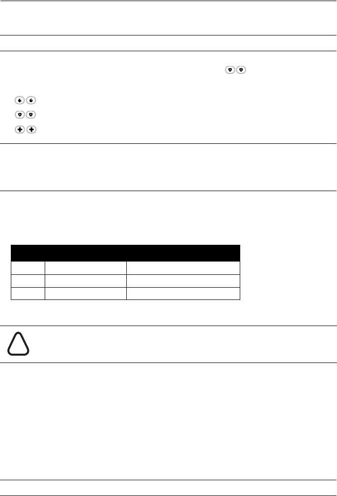
Table 5-1 Alarm Types
Priority Type of Alarm What you hear
1 Fire Temporal/ Pulsed Siren
2 Carbon Monoxide 4 beeps, 5 second pause, 4 beeps
3 Intrusion (Burglary) Continuous Siren
If you are unsure of the source of the alarm approach with caution!
If the Intrusion alarm was accidental
1. Enter your Access Code to silence the alarm.
2. Call your central station to avoid a dispatch.
If the Fire Alarm was Accidental (i.e. burned toast, bathroom steam, etc.)
1. Enter your Access Code to silence the alarm.
2. Call your central station to avoid a dispatch.
NOTE: Verify with your alarm company that your system is equipped with fire detection.
!
DRAFT 3
5 Emergency Keys and Alarms
18
5.3 Carbon Monoxide Alarm - 4 beeps, long pause, 4 beeps
Activation of your CO alarm indicates the presence of carbon monoxide (CO), which can be fatal. During
an alarm:
• The red LED on the CO detector flashes rapidly and buzzer sounds with a repeating cadence of:
4 quick beeps, 5-second pause, 4 quick beeps.
• The siren connected to the control panel produces the same cadence as above.:
• The keypad provides audible and visual indication of the CO alarm.
5.4 Resetting Sensors
After having detected an alarm condition certain sensors require a reset to exit the alarm condition (i.e.
glass break sensors, smoke detectors, etc.).
5.5 Viewing Alarms in memory
When an alarm occurs the keypad indicator illuminates. Viewing the Alarm memory provides more
information on the sensor(s) that were tripped.
5.5.1 Alarm Messages
WARNING: Carefully review your Carbon Monoxide Alarm Installation/User Guide to determine the
necessary actions required to ensure your safety and ensure that the equipment is operating
correctly. Incorporate the steps outlined in the guide into your evacuation plan.
If the Carbon Monoxide Alarm Sounds
1. Operate silence button.
2. Call emergency services or your fire department.
3. Immediately move outdoors or to an open door/window.
NOTE: Verify with your alarm company if this function is required on your system.
To Reset the Sensors
• Press and hold on the keypad for 2 seconds. If the sensor reset is successful, the alarm is can-
celled.
• If a sensor fails to reset, it may still be detecting an alarm condition. If unsuccessful, the alarm will
reactivate or continue.
To View Alarms in Memory What you see
• Press
OR
use the scroll keys to navigate to Alarm Memory and press .
The Alarm information will display. For more information on the messages
that could be displayed see 5.5.1 “Alarm Messages”.
Press (*) for <>
Alarm Memory
What you see What it means
Burglary <>
Verified Multiple burglary sensors were tripped. Central station has been notified.
Burglary Not <>
Verified A single burglary sensor was tripped. Central station has been notified.
Fire Alarm <>
Fire Zone 1 Fire alarm has been triggered. Central station has been notified.
CO Alarm <>
CO Zone 1 <> CO alarm has been triggered. Central station has been notified.
*
3
*
DRAFT 3
19
6 Wireless Keys and other Devices
In addition to the keypad, the HS Series system can be controlled using a variety of devices:
• 2-way wireless keys
• Proximity Tags
• via SMS using a cellphone.
6.1 Using the 2-way Wireless Key
2-way wireless keys allow users in the close proximity of their house the ability to readily arm/disarm their
system, and to call for help. For information on enrolling wireless keys see 7.1.3 "Enrolling Wireless
Keys".
6.2 Using Proximity Tags
Proximity tags are ideal for people who have difficulties remembering codes or who do not interact with
the system regularly. To operate properly Proximity tags must be enrolled in the system.
For more information see 7.1.2 "Enrolling and Deleting Proximity Tags".
6.3 SMS Command and Control
SMS Command and Control allows you to send text messages to your system, enabling the system to
perform certain actions. For a list of commands and how to send them see Table 6-1. As a security measure,
only phone numbers configured by your installer will be permitted to contact your system. Messages from
all other phone numbers will be rejected.
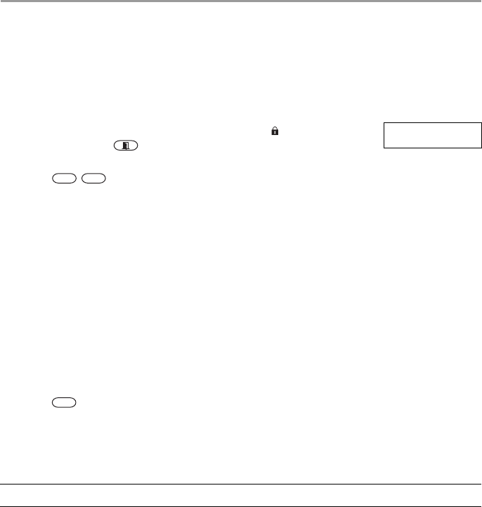
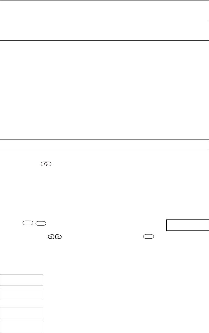
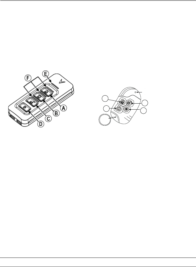
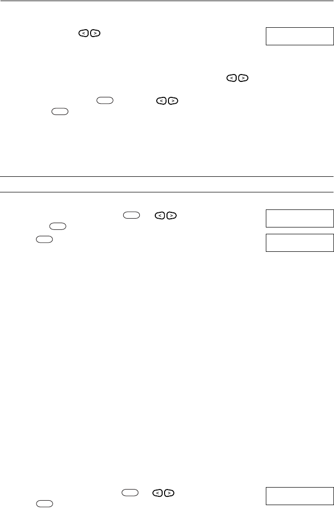
Figure 6-1 PGx929 Figure 6-2 PGx939
A Arm "Away" / Arm "Latchkey" AArm "Away"
BArm "Home" BArm "Home"
CDisarm CLED
DAux DDisarm
ETransmission LED EAux
FStatus LEDs
NOTE: Must be enabled and configured by installer.
1
2
LED
3
4
DRAFT 3
6 Wireless Keys and other Devices
20
6.3.1 Using the Keypad to Lookup the Number to Call for SMS Commands
The phone number of the system is programmed by the installer. To quickly find the phone number
perform the following steps.
6.3.2 Sending SMS Commands to your System
In order to successfully send commands to your system from your cellphone, you must send SMS messages
in the proper format. If configured, commands require the inclusion of a User Access Code in your
message. The access code will be verified by the system before executing any commands.
Additional information about sending SMS commands:
• Text messages are not case sensitive and extra spaces are ignored.
• In multi-partition systems and if the User has rights to manage the desired partitions, commands can
be sent to specific partitions by including the partition number. For more information on partitions see
section 10 "Managing Partitions".
• If the panel is configured to require an Access Code and the code is not sent or is invalid, the panel
will send a notification to the user advising the command was unsuccessful.
Table 6-1 lists all available SMS commands with examples of how to enter the Partition number and access
codes. The format for entering commands is as follows:
To find the System’s Phone Number What you see
1. Check that the Ready indicator is on and the system is disarmed. Date Time
JAN 02/13 2:06a
2. Press
OR
press and use the scroll keys to navigate to User Functions and
press . If required enter your [access code].
Press (*) for <>
User Functions
3. Press or use the scroll keys to navigate to SMS Pro-
gramming and press
Press (*) for <>
SMS Programming
4. Scroll to navigate to SMS Programming and press . The phone
number to send your SMS commands to displays.
Press (*) for <>
GSM Phone No.
Command Partition number Access Code
Stay Arm 001 1234
NOTES: Verify with your installer that the Partition number and access code are required in your SMS
message. If one or both are not required, do not enter them in your SMS message.
Responses to Status and Alarm Memory requests may require more than 1 SMS message,
depending on status of the system. There is a 10 second delay between transmission of SMS
messages.
Table 6-1 SMS Commands
Commands Notes
Stay Arm Stay arms the system.
Away Arm Away arms the system.
Night Arm Night arms the system.
Disarm Disarms the system.
Activate Command Output 1 Activates Output 1.
*
6
*
*
1 1
*
*
DRAFT 3

6 Wireless Keys and other Devices
21
6.3.3 SMS Responses from your System
SMS responses are sent to the phone that initiated the command.
Activate Command Output 2 Activates Output 2.
Activate Command Output 3 Activates Output 3.
Activate Command Output 4 Activates Output 4.
Deactivate Command Output 1 Deactivates Output 1.
Deactivate Command Output 2 Deactivates Output 2.
Deactivate Command Output 3 Deactivates Output 3.
Deactivate Command Output 4 Deactivates Output 4.
Bypass 001 Bypasses specified zone number.
Unbypass 001 Clears the bypass from the specified zone number.
Status Request Omitting the partition number causes the system to send a status report
for all partitions. To request a status report for a specific partition enter
the appropriate partition number.
Alarm Memory Request Omitting the partition number causes the system to send a status report
for all partitions. To request a status report for a specific partition enter
the appropriate partition number.
Help The Help command generates an SMS response listing all Interactive
commands that can be sent to the module. Access Code is not required.
Table 6-2 System SMS Responses
System Response Notes
Successful Sent when a command and control function is successfully performed by
the panel
Unsuccessful Sent when a command and control function not successfully
performed by the panel
Invalid Command Sent when a command sent was not accepted as valid by the system.
System Stay Armed Sent in response to a status request and if a partition is stay armed
System Away Armed Sent in response to a status request and if a partition is away armed
System Night Armed Sent in response to a status request and if a partition is night armed
System Disarmed Ready Sent in response to a status request and if a partition is disarmed and
ready to arm.
System Disarmed Not Ready Sent in response to a status request and if a partition is disarmed and is
not ready to arm.
System is in Alarm Sent in response to a status request and if a partition is in alarm.
Service is Required Sent in response to a status request and if a partition is in trouble.
No Alarm Memory Sent in response to a alarm memory request and there are no alarms in
memory.
Table 6-1 SMS Commands (Continued)
Commands Notes
DRAFT 3
22
7 Managing Users
7.1 User Codes
Up to 95 different users can be programmed in the HS Series. Each user can be:
• Uniquely labeled.
• Assigned an access code.
• Assigned a proximity tag and/or wireless key (key fob). In order to operate, proximity tags and wire-
less keys must be enrolled in the system.
• Assigned to only operate specific partitions. For more information on partitions see section 10 "Man-
aging Partitions".
• Configured with additional attributes. For more information see 7.2 "Configuring additional User
Options".
Programed zones are flagged in the LCD screen. For more information on user flags see Table 7-1.
NOTE: Your installer configures all access codes to be either 4 or 6 digits. You cannot have access codes
of both lengths on your system.
Table 7-1 User Flags
LCD Display Flag Description
User Code 01 -
- Unprogrammed code.
User Code 01 P
P Programmed code.
User Code 01 T T Code and tag/key are programmed.
To Access the User Codes Menu What you see
1. Press
OR
press and use the scroll keys to navigate to User Codes and
press .
Press (*) for <>
User Functions
2. Enter [Master or supervisor code] and scroll through the list of Users. To edit a
desired user press .
Enter Master
Access Code
then
Press (*) for <>
{User Label}
3. To go back to the Ready state press .
*
5
*
*
*
#
DRAFT 3
7 Managing Users
23
7.1.1 Access Codes
Each configured user is assigned a number from 01-95. When creating access codes the following criteria
applies:
• Codes cannot be duplicated.
• New codes must differ from existing codes by more than one digit (e.g., if 1234 exists, 1235 is
invalid).
7.1.2 Enrolling and Deleting Proximity Tags
When enrolling or deleting proximity tags for a user, the system provides a choice of option depending on
if tag is already enrolled or not. For more information on see 6.2 "Using Proximity Tags".
To Add or Change User Access Codes What you see
1. From the User Codes menu scroll to the label or enter the number of
the desired user (01-95) and press .
Press (*) for <>
User Code 03 -
2. Press or . Press (*) for <>
Access Code
3. Enter a new 4 or 6 digit access code. After entering a new code you will be
automatically returned to the previous menu and the flag is changed to P from
-. If a duplicate code is entered the error tone will sound.
Enter New Code
XXXXXX
then
Press (*) for <>
User Code 03 P
To Delete a User Access Code What you see
1. From the User Codes menu scroll to the label or enter the number of
the desired user (01-95) and press .
Press (*) for <>
User Code 03 P
1. Press or . Press (*) for <>
Access Code
2. Scroll to the desired user code and press . (*) to Edit <>
User Code 03 P
3. Press and the code is deleted, and you are returned to the previous
screen. The flag is changed to - from P.
Enter New Code
030516
then
(*) to Edit <>
User Code 03 -
To Enroll a Proximity Tag What you see
1. From the User Codes menu press or scroll to Prox Tag and
press .
Press (*) for <>
Prox Tag
2. If no tag is enrolled for this user you will be asked to present the tag to the
reader.
Present Tag or
Press # to Exit
• If the card successfully enrolls. Tag Enrolled
Successfully
• If the tag is invalid. Invalid Tag
Not Enrolled
• If the tag already is enrolled with another user. Duplicate Tag
Not Enrolled
*
*
1
*
*
1
*
*
2
*
DRAFT 3
7 Managing Users
24
7.1.3 Enrolling Wireless Keys
When enrolling or deleting wireless keys the system provides a choice of option depending on if key is
enrolled or not. For more information see 6.1 "Using the 2-way Wireless Key".
7.1.4 Naming a User
Adding or editing labels is accomplished by using the keypad to input the desired letters or numbers. Figure
7-1 depicts the three letters and one number that corresponds to each keypad button.The first press of the
number key displays the first letter. The second press displays the second letter, etc.
Figure 7-1 Entering letters using the keypad
To Delete a Proximity Tag What you see
1. From the User Codes menu press or scroll to Prox Tag and
press .
Press (*) for <>
Prox Tag
2. If a tag is enrolled for this user you will be asked if you would like to delete
the Tag. Press to delete the tag.
* To Delete Tag
Press # to Exit
Tag Deleted
Successfully
To Enroll a Wireless Key What you see
1. From the User Codes menu press or scroll to Keyfob and press
or press.
Press (*) for <>
Keyfob
2. If no key is enrolled for this user you will be asked to enroll the key or enter
the ID. Either press a button on the wireless key or use the keypad to enter in
the ID number.
Enroll Now or
Entr ID:XXX-XXXX
Device Enrolled
Successfully
To Delete a Wireless Key What you see
1. From the User Codes press or menu scroll to Keyfob and press
.
Press (*) for <>
Keyfob
2. If a key is enrolled for this user you will be asked if you would like to delete
the key. Press to delete the key.
* To Delete Key
Press # to Exit
Key Deleted
Successfully
A, B, C, 1 D, E, F, 2 G, H, I, 3
J, K, L, 4 M, N, O, 5 P, Q, R, 6
S, T, U, 7 V, W, X, 8 Y, Z, 9,0
Space
To Edit a User Label What you see
1. From the User Codes menu press or scroll to User Labels and
press .
Press (*) for <>
User Labels
2
*
*
3
*
3
*
*
1
2
3
4
5
6
7
8
9
0
4
*
DRAFT 3
7 Managing Users
25
7.1.5 Assigning a Partition to a User code
User codes can be configured to have access only to specific partitions. For more information see section
10 "Managing Partitions".
7.2 Configuring additional User Options
Users can also be assigned the following options:
2. Use the arrow keys to move the cursor to a blank space or existing
character.
Program Name
{User 1 Label}
3. Press the number key corresponding to the appropriate letter as shown in Fig-
ure 7-1.
4. When the required letter or number is displayed use the arrow keys to
scroll to the next letter.
5. When finished, press the key, use the keys to scroll to Save
then press .
NOTE: Partitions are configured by your installer.
To Assign a Partition to a User code What you see
1. From the User Codes menu press or scroll to Partition Assign
and press .
Press (*) for <>
Partition Assign
2. Press to toggle assigning, Y or N, the partition to the user. (*) To Toggle <>
{Partition Lb} Y
Supervisor Use when you want to allow additional users to manage User Codes or User
Functions. Supervisor codes created by the master code will have the same
attributes as the master code. Supervisor codes created by another supervisor
code will have the same attributes, except the supervisor attribute. Must be
assigned manually afterwards. After creation, attributes can be changed for all
supervisor codes.
Duress Code Use when forced to access your keypad under threat. A Duress Code operates
your system normally but transmits a Duress Report to your monitoring sta-
tion.
Zone Bypass Grants the user the ability to bypass zones.
Remote Access Grants the user the ability to use SMS features. For more information see 6.3
"SMS Command and Control"
Bell Squawk Use to generate a bell squawk when arming/disarming the system.
One Time Use Use when needing to grant someone one time access to your home for a 24-
hour period, i.e., a cleaning person or contractor. During the 24-hour period the
user can only disarm the system once, but has no restriction on the number of
times they can arm the system.
To Configure additional User Options What you see
1. From the desired user code press or scroll to User Options and
press .
Press (*) for <>
User Options
To Edit a User Label (Continued) What you see
*
*
5
*
*
6
*
DRAFT 3