Tyco Safety Canada 13HS2KWFPV9 PowerG Wirefree Keypad with prox User Manual
Digital Security Controls Ltd. PowerG Wirefree Keypad with prox
UserManual.wiki
>
Tyco Safety Canada
>
13HS2KWFPV9 User Manual
User Manual
Navigation menu
Upload a User Manual
Namespaces
Wiki Guide
HTML
PDF
Info
Views
User Manual
Discussion / Help
Navigation
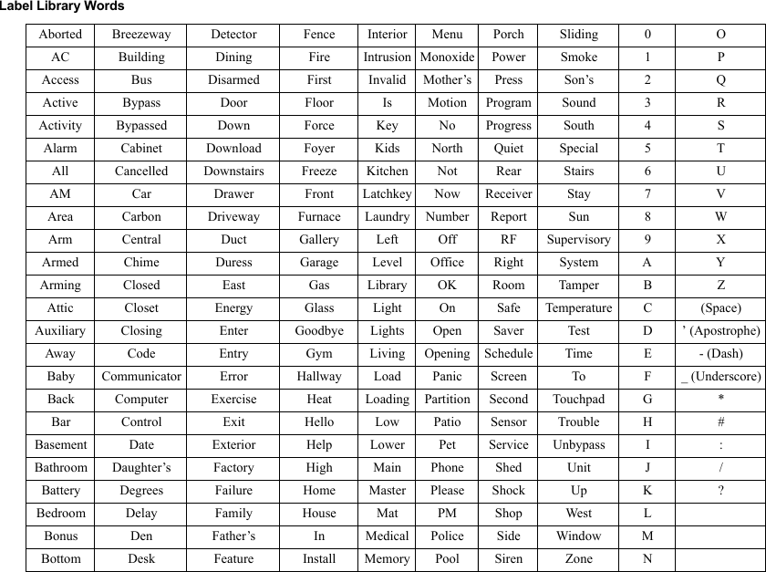
![CAUTION: Do not mix old batteries with new ones.Apply AC Power1. Slide the keypad up and out from the mountingplate / desk stand.2. Locate the power adaptor jack at the back of thekeypad housing.3. Place the adaptor plug in the housing indentation,perpendicular to the keypad. Insert the adaptorplug firmly into the jack.4. Pivot the adaptor plug downwards so that it fitsflush with the housing. Guide the AC wire alongthe channel provided in the keypad housing; thewire will extend through the bottom of the hous-ing.5. Replace the keypad on the mounting plate/deskstand (in the latter case, a further channel is pro-vided in the bottom of the desk stand. Guide theAC wire along this channel; the wire will extendthrough an opening in the back of the stand).6. Plug the adaptor into a wall outlet.NOTE: Only use the power adaptor (4.5VDC, 0.5A, 2.25W,limited power supply model XX) supplied with the kit.CAUTION: The socket-outlet in which the direct plug-inadaptor is inserted must be close to the keypad, easilyaccessible, and have unobstructed access. The plug of theadaptor serves as a means of disconnection from the sup-ply mains.Programming the KeypadThere are several programming options available forthe keypad (see below). Programming the keypad issimilar to programming the rest of the system. Toturn an option on/off, press the number correspond-ing to the option on the number pad. The numbers ofthe options that are currently turned on will be dis-played along the top of the LCD. For information onprogramming the rest of your security system, pleaserefer to your system’s Installation Manual. Language ProgrammingTo enter language programming, enter programming sec-tion [000] then subsection [000]. Then enter the two-digit number that corresponds to the language desired: Enrolling the KeypadThe HSM2HOST wireless transceiver must beenrolled onto the alarm panel before any wirelessdevices can be enrolled.When the alarm system is powered up for the firsttime, the first keypad or the HSM2HOST (if using awireless keypad as the first keypad) can be enrolled.To do this:1. Once the HSM2HOST is wired to the alarm paneland power has been applied, power up a wirelesskeypad.2. Press any button on the keypad to enroll it on theHSM2HOST. The HSM2HOST is then automaticallyenrolled on the alarm panel. Enrolling Keypad1. Enter [][8][Installer Code] and then section[804] > 000.2. When prompted, either activate the device toenroll immediately or enter a device serial num-ber. Do the latter to pre-enroll devices then enrollthem later at the customer site.3. Use the scroll keys or type in the correspondingnumber to select an option.4. Scroll through the available selections, key in anumber or enter text as appropriate.5. Press [*] to accept and move to the next option.6. Once all options are configured, the systemprompts to enroll the next device.7. Repeat the process described above until all wire-less devices are enrolled.Deleting Keypad1. Enter [][8][Installer Code] and then section[804] > 905.2. Use the scroll keys to select the keypad or press[#] to exit. 3. Select [*] to delete. The screen will read “Keypaddeleted”. Disassemble Keypad1. Insert the tip of a flat-head screwdriver into theslot at the bottom left section of the keypad. 2. Gently lower the handle of the screwdriver, open-ing the left side of the unit’s faceplate. 3. Repeat steps 1 and 2 using the slot at the bottom-right section of the unit. This will remove theunit’s faceplate and allow access for mounting. Applying Battery Power1. Slide the keypad up and out from the mountingplate/desk stand (removing the screws first ifrequired). The bay for the four AA batteries isopen and visible at the back of the keypad.2. Insert the batteries as directed on the back of thekeypad. Ensure the correct polarity is observed.3. Replace the keypad on the mounting plate/deskstand.CAUTION: Do not mix old batteries with new ones.Apply AC Power1. Slide the keypad up and out from the mountingplate/desk stand.2. Locate the power adaptor jack at the back of thekeypad housing.PlugMountingHolesMountingHolesWire channel01 = English (default)02 = Spanish03 = Portuguese04 = French05 = Italian06 = Dutch07 = Polish08 = Czech09 = Finnish10 = German11 = Swedish12 = Norwegian13 = Danish14 = Hebrew15 = Greek16 = Turkish17 = FFU18 = Croatian19 = Hungarian20 = Romanian21 = Russian22 = Bulgarian23 = Latvian24 = Lithuanian25 = Ukrainian26 = Slovakian27 = Serbian28 = Estonian29 = Slovenian](https://usermanual.wiki/Tyco-Safety-Canada/13HS2KWFPV9/User-Guide-2073125-Page-3.png)
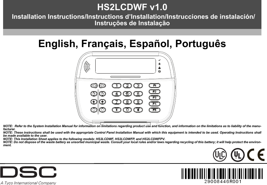
![3. Place the adaptor plug in the housing indentation, perpendicular to the key-pad. Insert the adaptor plug firmly into the jack.4. Pivot the adaptor plug downwards so that it fits flush with the housing.Guide the AC wire along the channel provided in the keypad housing; thewire will extend through the bottom of the housing.5. Replace the keypad on the mounting plate/desk stand (in the latter case, afurther channel is provided in the bottom of the desk stand. Guide the ACwire along this channel; the wire will extend through an opening in the backof the stand).6. Plug the adaptor into a wall outlet.NOTE: Only use the power adaptor (9.0VDC, 1.25A, 11.25W) supplied with the kit.CAUTION: The socket-outlet in which the direct plug-in adaptor is inserted must beclose to the keypad and easily accessible. Never obstruct the access to the socket out-let. The plug of the adaptor serves as a means of disconnection from the supply mains. Programming Labels 1. Use this section to assign a meaningful name (e.g., Front Door, Hallway,etc.) to each zone.2. Enter Keypad Programming by pressing [][8][Installer Code][]. 3. Enter the 3-digit section number for the label to be programmed.4. Use the arrow keys (<>) to move the cursor underneath the letter to bechanged.5. Press number key 1 through 9, corresponding to the letter you require. Forexample, pressing number key 2 once will display the letter D; pressing itagain will display the letter E; pressing it a third time will display the letterF, and so on.6. When the required letter or number is displayed use the arrow keys (<>) toscroll to the next letter.7. When you are finished programming the Zone Label, press []. Scroll to‘Save’ and press [] again.8. Repeat Steps 3 through 7 until all Labels are programmed.ASCII CharactersLabel LibraryThe Label Library is a database of words commonly used when programming labels.Individual words can be combined as needed. e.g., Front + Door. Each line of the dis-play supports a maximum of 14 characters. If a word will not fit on a line, scroll rightuntil the cursor appears at the first character of the second line then add the word.To program a custom label using the Label Library:1. Enter keypad programming and select the label to change. e.g.,[*][8][Installer Code][000][001] (to program the label for zone 01).2. Press [*] to open the “Select Options” menu.3. Press [*] again to select the “Words” option.4. Enter the 3-digit number corresponding to a word (see Words table below)or use the scroll keys [<][>] to view words in the library.5. Press [*] to select the word.6. To add another word, repeat the above procedure from step 2.7. To add a space, press the right scroll key [>].8. To clear characters, select “Clear to End” or “Clear Display” from the“Select Options” menu.9. To save the current label, press [*] to access the “Select Options” menu,scroll left [<] to “Save” then press [*] again.Broadcasting LCD LabelsIf more than one LCD keypad is present on the system, labels programmed atone keypad will be broadcast to all other LCD keypads right after the change isconfirmed.Voice Prompt/Voice ChimeVoice Prompt Control (for wireless keypads only)Menu: [*][6][access code] > Voice Control > Voice PromptKeypad: [*][6][access code]This function is used to change the volume level of keypad voice prompts, forexample, “User arming in progress.” The voice prompt speaks the zone labelsprogrammed for zone openings/closings. Use the scroll keys (LCD/touchscreenkeypads) or the [*] key (LED/ICON keypads) to increase and decrease volumeor enter a value from 00 to 15. Selecting 00 turns off keypad voice prompts.Voice Chime ControlMenu: [*][6][access code] > > Voice Control > Chime ControlKeypad: [*][6][access code]This function is used to change the keypad voice chime volume level. Use thescroll keys (LCD/touchscreen keypads) or the [*] key (LED/ICON keypads) toincrease and decrease voice chime volume or enter a value from 00 to 15.Selecting 00 turns off voice chime.NOTE: This feature is only available when the voice prompt feature is enabled. Changing Brightness/Contrast/Buzzer/LCD Keypads1. Press [][6][Master Code].2. Use the [<][>] keys to scroll to either Brightness/LED Bar Control, Contrast Con-trol, Buzzer Control, or Voice Control. 3. Press [] to select the setting you want to adjust.4. a) Brightness/LED Bar Control: There are 15 backlighting levels. Use the [<][>]keys to scroll to the desired level. Changing this level adjusts the LED bar accord-ingly. b) Contrast Control: There are 15 different display contrast levels. Use the [<][>]keys to scroll to the desired contrast level.[1] - A, B, C, 1 [4] - J, K, L, 4 [7] - S, T, U, 7 [0] - Space[2] - D, E, F, 2 [5] - M, N, O, 5 [8] - V, W, X, 8 [*] - Select[3] - G, H, I, 3 [6] - P, Q, R, 6 [9] - Y, Z, 9,0 [#] - Escape](https://usermanual.wiki/Tyco-Safety-Canada/13HS2KWFPV9/User-Guide-2073125-Page-4.png)
![c) Buzzer Control: There are 15 different buzzer control levels. Use the [<][>] keys to scroll to the desired contrast level.Keypad LED SymbolsProximity Tags (HS2LCDWFP, HS2LCDWFPV only)The proximity tag can be used to perform any keypad function that would nor-mally require a user access code. The tag is to be presented to the face of thekeypad. While the keypad is running off AC, the transceiver is always on todetect any prox tag approaching. While the keypad is running on battery and insleep mode, the user can press any key to wake the keypad, then present theprox tag. Enrolling Proximity TagsEnrolling a tag on one keypad will enroll it automatically to all HS2LCDWFPor HS2LCDWFPV keypads enrolled on the system.1. Enter [][5] and an access code with the supervisor attribute enabled. 2. Select or enter a two-digit User Code slot (02-95) to be associated with theproximity tag. Alternatively, scroll to the two-digit user number and pressthe [] key. 3. Scroll to ‘Press [] for Prox Tag’ and press the [] key. 4. The screen will prompt “Present Your Prox Tag”; do so or press the [#] keyto exit.5. Present your proximity tag to the keypad. If enrollment is successful,acknowledgement beeps will sound and the keypad LCD will read ‘TagEnrolled Successfully’. If enrollment is unsuccessful, an error tone willsound and the keypad will read ‘Invalid Tag Not Enrolled’. If the tag hasbeen enrolled previously, an error tone will sound. Deleting Proximity TagsDelete the prox tags from the system when they are lost or no longer needed.1. Enter [][5] and an access code with the supervisor attribute enabled. 2. The keypad will display the user number and include the letter ‘T’ if a proxtag is programmed.3. Scroll to ‘Press [] for Prox Tag’ and press the [] key.4. The keypad will read ‘Press [] To Delete Tag’. 5.After pressing [], the message ‘Tag Deleted Successfully’ appears. NOTE: User codes can only be deleted individually. NOTE: User 01 - Master Code cannot be deleted; a deletion attempt on this user code willdelete the proximity tag only.NOTE: A user code, once deleted, must be re-enrolled before it can be used again.Keypad Function Key ProgrammingTo program a function key:1. Enter Installer Programming by entering [][8][Installer Code].2. Press [861] for keypad programming. Section [860] is read-only and showsthe slot number of the keypad being accessed. 3. Enter [001]-[005] for function keys 1-5. 4. Enter a 2-digit number to assign a function key operation - [00]-[68]. Seetable below.5. Continue from step 3 until all function keys are programmed.6. Press the [#] key twice to exit Installer Programming.[001]-[005] Function Key AssignmentSymbol DescriptionReady Light (Green) If Ready light is ON, the system is ready to arm.Armed Light (Red) If Armed light is ON/Flashing, the system has been armed successfully.System Trouble (Yellow) ON - Indicates that a system trouble is active.Flashing - Keypad low battery.AC (Green) ON - Indicates that AC is present at the keypad.Section FunctionKey Button Valid Range Default Function[001] 1 00 - 68 03 Stay Arm I_______I_______I[002] 2 00 - 68 04 Away Arm I_______I_______I[003] 3 00 - 68 01 Disarm I_______I_______I[004] 4 00 - 68 52 [P] Key Alarm I_______I_______I[005] 5 00 - 68 16 Quick Exit I_______I_______I](https://usermanual.wiki/Tyco-Safety-Canada/13HS2KWFPV9/User-Guide-2073125-Page-5.png)
![Keypad Function KeysPlease see your system installation manual for more details on the function keyoptions below.Keypad ProgrammingEnter keypad programming by entering Installer Programming, then Section [861] to[876], which apply to keypads 1-16.[860] Keypad Slot NumberThis is not for programming; the two-digit slot number is displayed for information only.[861]-[876] Keypad Programming Sections[000] Address of PartitionUpon selecting [000], a 2-digit entry is required to assign the keypad to a partition. Entering 00 assigns the keypad as global. Valid entries are 00-32. The default is 01. [001]-[005] Function Key 1-5 Assignment[011] Keypad Input/Output Programming [012] Local PGM Output Pulse Activation Time[021] First Keypad Options[022] Second Keypad Options [00] - Null [16] - Quick Exit [37]-[50] For Future Use[01] - Disarm [17] - Arm Interior [51]- [A] Key Alarm [02] - Instant Stay Arm [18]-[20] - For Future Use [52] - [P] Key Alarm[03] - Stay Arm [21] - Command Output 1 [53] - [92] For Future Use[04] - Away Arm [22] - Command Output 2[05] - [*][9] No-Entry Arm [23] - Command Output 3[06] - Chime ON/OFF [24] - Command Output 4[07] - System Test [25]-[28] - For Future Use[08] - For Future Use [29] - Bypass Group Recall[09] - Night Arm [30] - Quick Bypass[10] - For Future Use [31] - For Future Use[11] - Away Arm no Entry [32] - For Future Use[12] - Global Stay Arm [33] - Bypass Recall[13] - Global Away Arm [34] - For Future Use[14] - Global Dis-arming [35] - For Future Use[15] - For Future Use [36] - Reactivate Stay/Away and Night ZonesDefaultZone or PGM Number 00 I_____I_____I_____II_____I_____I Minutes (00-99)I_____I_____I Seconds (00-99)Default Opt. ON OFFON I_____I 1 Fire Key Enabled Fire Key DisabledON I_____I 2 Medical Key Enabled Medical Key DisabledON I_____I 3 Panic Key Enabled Panic Key DisabledON I_____I 4 Display Access Code When ProgrammingDisplay X’s When Pro-gramming Access CodesOFF I_____I 5 For Future Use For Future UseOFF I_____I 6 For Future Use For Future UseOFF I_____I 7 For Future Use For Future UseOFF I_____I 8 For Future Use For Future UseDefault Opt. ON OFFON I_____I 1 Local Clock Display ON Local Clock Display OFFOFF I_____I 2 Local Clock Displays 24-hr TimeLocal Clock Displays AM/PMON I_____I 3 Auto Alarm Scroll ON Auto Alarm Scroll OFFOFF I_____I 4 For Future Use For Future UseOFF I_____I 5 Power LED Enabled Power LED Disabled](https://usermanual.wiki/Tyco-Safety-Canada/13HS2KWFPV9/User-Guide-2073125-Page-6.png)
![[023] Third Keypad Options [030] LCD Message[031] Downloaded LCD Message Duration Default: 000 I_____I_____I_____I (Valid entries are 000-255), 000=Unlimited Message DisplayThis number represents the number of times the downloaded message must becleared before it is permanently removed. This message can be cleared by press-ing any key.[101]-[228] Door Chime for Zones 1-128[999] Reset Keypad Programming to Factory Defaults1. Enter Installer’s Code. 2. Press [] or 999.Limited Warranty Digital Security Controls (DSC) warrants that for a period of 12 months from the date of purchase, the product shall be free ofdefects in materials and workmanship under normal use and that in fulfilment of any breach of such warranty, DSC shall, at itsoption, repair or replace the defective equipment upon return of the equipment to its repair depot. This warranty applies only todefects in parts and workmanship and not to damage incurred in shipping or handling, or damage due to causes beyond the controlof DSC such as lightning, excessive voltage, mechanical shock, water damage, or damage arising out of abuse, alteration orimproper application of the equipment. The foregoing warranty shall apply only to the original buyer, and is and shall be in lieu ofany and all other warranties, whether expressed or implied and of all other obligations or liabilities on the part of DSC. DSC neitherassumes responsibility for, nor authorizes any other person purporting to act on its behalf to modify or to change this warranty, norto assume for it any other warranty or liability concerning this product. In no event shall DSC be liable for any direct, indirect orconsequential damages, loss of anticipated profits, loss of time or any other losses incurred by the buyer in connection with thepurchase, installation or operation or failure of this product. WARNING: DSC recommends that the entire system be completelytested on a regular basis. However, despite frequent testing, and due to, but not limited to, criminal tampering or electrical disrup-tion, it is possible for this product to fail to perform as expected. Important Information: Changes or modifications not expresslyapproved by DSC could void the user’s authority to operate this equipment.EN50131-1 Grade 2, Class 2, EN50131-6 Type BImportant Information: Changes/modifications not expressly approved by DSC could void the user’s authority to operate thisequipment.IMPORTANT - READ CAREFULLY: DSC Software purchased with or without Products and Components is copyrighted and ispurchased under the following license terms:• This End-User License Agreement (“EULA”) is a legal agreement between You (the company, individual or entity whoacquired the Software and any related Hardware) and Digital Security Controls, a division of Tyco Safety Products CanadaLtd. (“DSC”), the manufacturer of the integrated security systems and the developer of the software and any related productsor components (“HARDWARE”) which You acquired. • If the DSC software product (“SOFTWARE PRODUCT” or “SOFTWARE”) is intended to be accompanied by HARDWARE,and is NOT accompanied by new HARDWARE, You may not use, copy or install the SOFTWARE PRODUCT. The SOFTWAREPRODUCT includes computer software, and may include associated media, printed materials, and “online” or electronic doc-umentation. • Any software provided along with the SOFTWARE PRODUCT that is associated with a separate end-user license agreementis licensed to You under the terms of that license agreement. • By installing, copying, downloading, storing, accessing or otherwise using the SOFTWARE PRODUCT, You agree uncondi-tionally to be bound by the terms of this EULA, even if this EULA is deemed to be a modification of any previous arrangementor contract. If You do not agree to the terms of this EULA, DSC is unwilling to license the SOFTWARE PRODUCT to You, andYou have no right to use it.SOFTWARE PRODUCT LICENSEON I_____I 6 Power LED Indicates AC Present ONPower LED Indicates AC Present OFFON I_____I 7 Alarms Displayed While Armed Alarms Not Displayed While Armed OFF I_____I 8 Auto-Scroll Open Zones ONAuto-Scroll Open Zones OFFDefault Opt. ON OFFOFF I____I 1 Armed LED On in Sleep Mode Armed LED Off in Sleep ModeON I____I 2 Keypad Status Shows Stay ArmKeypad Status Shows Stay/Away ArmOFF I____I 3 5th Terminal is Keypad PGM Output5th Terminal is Keypad Zone InputOFF I____I 4 For Future Use For Future UseOFF I____I 5 For Future Use For Future UseOFF I____I 6 For Future Use For Future UseOFF I____I 7 Temperature Display Enabled Temperature Display DisabledOFF I____I 8 Low Temperature Warning Enabled Low Temperature Warning Disabled NOTE: Programming options indicated in GREY are required for systems compliantwith EN50131-1 and EN50131-3 standards. Section [023]: 1=OFFI_____I_____I_____I_____I_____I_____I_____I_____I_____I_____I_____I_____I_____I_____I_____I_____|I_____I_____I_____I_____I_____I_____I_____I_____I_____I_____I_____I_____I_____I_____I_____I_____|[041] Indoor Temperature Zone AssignmentDefault: 000 I_____I_____I_____I (Valid entries are 000-128)[042] Outdoor Temperature Zone AssignmentDefault: 000 I_____I_____I_____I ( V alid entries are 000-128)The keypad can be programmed to make up to four different chime sounds for individual zones. e.g. for Zone 1 enter Section [101], for Zone 2 enter Section [102].Default Opt.ON I____I 1 6 beepsOFF I____I 2 ‘Bing-Bing’ tone OFF I____I 3 ‘Ding-Dong’ tone OFF I____I 4 Alarm tone (4 second duration)OFF I____I 5 Zone nameOFF I____I 6-8 For future use](https://usermanual.wiki/Tyco-Safety-Canada/13HS2KWFPV9/User-Guide-2073125-Page-7.png)
![The SOFTWARE PRODUCT is protected by copyright laws and international copyright treaties, as well as other intellectualproperty laws and treaties. The SOFTWARE PRODUCT is licensed, not sold. 1. GRANT OF LICENSE This EULA grants You the following rights:(a) Software Installation and Use - For each license You acquire, You may have only one copy of the SOFTWARE PRODUCTinstalled. (b) Storage/Network Use - The SOFTWARE PRODUCT may not be installed, accessed, displayed, run, shared or used concurrently onor from different computers, including a workstation, terminal or other digital electronic device (“Device”). In other words, if You haveseveral workstations, You will have to acquire a license for each workstation where the SOFTWARE will be used.(c) Backup Copy - You may make back-up copies of the SOFTWARE PRODUCT, but You may only have one copy per license installedat any given time. You may use the back-up copy solely for archival purposes. Except as expressly provided in this EULA, You may nototherwise make copies of the SOFTWARE PRODUCT, including the printed materials accompanying the SOFTWARE.2. DESCRIPTION OF OTHER RIGHTS AND LIMITATIONS (a) Limitations on Reverse Engineering, Decompilation and Disassembly - You may not reverse engineer, decompile, ordisassemble the SOFTWARE PRODUCT, except and only to the extent that such activity is expressly permitted by applicable lawnotwithstanding this limitation. You may not make any changes or modifications to the Software, without the written permission of an officerof DSC. You may not remove any proprietary notices, marks or labels from the Software Product. You shall institute reasonable measures toensure compliance with the terms and conditions of this EULA.(b)Separation of Components - The SOFTWARE PRODUCT is licensed as a single product. Its component parts may notbe separated for use on more than one HARDWARE unit.(c)Single INTEGRATED PRODUCT - If You acquired this SOFTWARE with HARDWARE, then the SOFTWARE PRODUCT islicensed with the HARDWARE as a single integrated product. In this case, the SOFTWARE PRODUCT may only be used withthe HARDWARE as set forth in this EULA.(d)Rental - You may not rent, lease or lend the SOFTWARE PRODUCT. You may not make it available to others or post it ona server or web site.(e)Software Product Transfer - You may transfer all of Your rights under this EULA only as part of a permanent sale ortransfer of the HARDWARE, provided You retain no copies, You transfer all of the SOFTWARE PRODUCT (including allcomponent parts, the media and printed materials, any upgrades and this EULA), and provided the recipient agrees to theterms of this EULA. If the SOFTWARE PRODUCT is an upgrade, any transfer must also include all prior versions of theSOFTWARE PRODUCT.(f)Termination - Without prejudice to any other rights, DSC may terminate this EULA if You fail to comply with the termsand conditions of this EULA. In such event, You must destroy all copies of the SOFTWARE PRODUCT and all of its componentparts.g)Trademarks - This EULA does not grant You any rights in connection with any trademarks or service marks of DSC or itssuppliers.3. COPYRIGHT - All title and intellectual property rights in and to the SOFTWARE PRODUCT (including but not limited to anyimages, photographs, and text incorporated into the SOFTWARE PRODUCT), the accompanying printed materials, and anycopies of the SOFTWARE PRODUCT, are owned by DSC or its suppliers. You may not copy the printed materialsaccompanying the SOFTWARE PRODUCT. All title and intellectual property rights in and to the content which may beaccessed through use of the SOFTWARE PRODUCT are the property of the respective content owner and may be protected byapplicable copyright or other intellectual property laws and treaties. This EULA grants You no rights to use such content. Allrights not expressly granted under this EULA are reserved by DSC and its suppliers.4. EXPORT RESTRICTIONS - You agree that You will not export or re-export the SOFTWARE PRODUCT to any country, person,or entity subject to Canadian export restrictions. 5. CHOICE OF LAW - This Software License Agreement is governed by the laws of the Province of Ontario, Canada.6. ARBITRATION - All disputes arising in connection with this Agreement shall be determined by final and binding arbitration inaccordance with the Arbitration Act, and the parties agree to be bound by the arbitrator’s decision. The place of arbitration shallbe Toronto, Canada, and the language of the arbitration shall be English.7. LIMITED WARRANTY(a) NO WARRANTY - DSC PROVIDES THE SOFTWARE “AS IS” WITHOUT WARRANTY. DSC DOES NOT WARRANT THAT THESOFTWARE WILL MEET YOUR REQUIREMENTS OR THAT OPERATION OF THE SOFTWARE WILL BE UNINTERRUPTED ORERROR-FREE.(b) CHANGES IN OPERATING ENVIRONMENT - DSC shall not be responsible for problems caused by changes in theoperating characteristics of the HARDWARE, or for problems in the interaction of the SOFTWARE PRODUCT with non-DSC-SOFTWARE or HARDWARE PRODUCTS.(c) LIMITATION OF LIABILITY; WARRANTY REFLECTS ALLOCATION OF RISK - IN ANY EVENT, IF ANY STATUTE IMPLIESWARRANTIES OR CONDITIONS NOT STATED IN THIS LICENSE AGREEMENT, DSC’S ENTIRE LIABILITY UNDER ANY PROVISION OF THISLICENSE AGREEMENT SHALL BE LIMITED TO THE GREATER OF THE AMOUNT ACTUALLY PAID BY YOU TO LICENSE THE SOFTWAREPRODUCT AND FIVE CANADIAN DOLLARS (CAD$5.00). BECAUSE SOME JURISDICTIONS DO NOT ALLOW THE EXCLUSION ORLIMITATION OF LIABILITY FOR CONSEQUENTIAL OR INCIDENTAL DAMAGES, THE ABOVE LIMITATION MAY NOT APPLY TO YOU.(d) DISCLAIMER OF WARRANTIES - THIS WARRANTY CONTAINS THE ENTIRE WARRANTY AND SHALL BE IN LIEU OF ANY AND ALLOTHER WARRANTIES, WHETHER EXPRESSED OR IMPLIED (INCLUDING ALL IMPLIED WARRANTIES OF MERCHANTABILITY OR FITNESSFOR A PARTICULAR PURPOSE) AND OF ALL OTHER OBLIGATIONS OR LIABILITIES ON THE PART OF DSC. DSC MAKES NO OTHERWARRANTIES. DSC NEITHER ASSUMES NOR AUTHORIZES ANY OTHER PERSON PURPORTING TO ACT ON ITS BEHALF TO MODIFY OR TOCHANGE THIS WARRANTY, NOR TO ASSUME FOR IT ANY OTHER WARRANTY OR LIABILITY CONCERNING THIS SOFTWARE PRODUCT.(e) EXCLUSIVE REMEDY AND LIMITATION OF WARRANTY - UNDER NO CIRCUMSTANCES SHALL DSC BE LIABLE FOR ANYSPECIAL, INCIDENTAL, CONSEQUENTIAL OR INDIRECT DAMAGES BASED UPON BREACH OF WARRANTY, BREACH OF CONTRACT,NEGLIGENCE, STRICT LIABILITY, OR ANY OTHER LEGAL THEORY. SUCH DAMAGES INCLUDE, BUT ARE NOT LIMITED TO, LOSS OFPROFITS, LOSS OF THE SOFTWARE PRODUCT OR ANY ASSOCIATED EQUIPMENT, COST OF CAPITAL, COST OF SUBSTITUTE ORREPLACEMENT EQUIPMENT, FACILITIES OR SERVICES, DOWN TIME, PURCHASERS TIME, THE CLAIMS OF THIRD PARTIES, INCLUDINGCUSTOMERS, AND INJURY TO PROPERTY. WARNING: DSC recommends that the entire system be completely tested on aregular basis. However, despite frequent testing, and due to, but not limited to, criminal tampering or electricaldisruption, it is possible for this SOFTWARE PRODUCT to fail to perform as expected.FCC Compliance StatementCaution: Changes or modifications not expressly approved by Digital Security Controls could void your authority to use thisequipment.This equipment generates and uses radio frequency energy and if not installed and used properly, in strict accordance with themanufacturer’s instructions, may cause interference to radio and television reception. It has been type tested and found to complywith the limits for Class B device in accordance with the specifications in Subpart “B” of Part 15 of FCC Rules, which are designedto provide reasonable protection against such interference in any residential installation. However, there is no guarantee thatinterference will not occur in a particular installation. If this equipment does cause interference to television or radio reception, whichcan be determined by turning the equipment off and on, the user is encouraged to try to correct the interference by one or more ofthe following measures: (i) Re-orient the receiving antenna; (ii) increase the separation between the equipment and receiver; (iii)connect the equipment into an outlet on a circuit different from that to which the receiver is connected. If necessary, the user shouldconsult the dealer or an experienced radio/television technician for additional suggestions. The user may find the following bookletprepared by the FCC helpful: “How to Identify and Resolve Radio/Television Interference Problems”. This booklet is available fromthe U.S. Government Printing Office, Washington, D.C. 20402, Stock # 004-000-00345-4.This Class B digital apparatus complies with Canadian ICES-003.Cet appareil numérique de la classe B est conforme à la norme NMB-003 du Canada. IC:160A-HS2LCDWF The term IC before theradio certification number signifies that the Industry Canada technical specifications were met. The trademarks, logos, and service marks displayed on this document are registered in the United States [or other countries]. Anymisuse of the trademarks is strictly prohibited and Tyco International Ltd. will aggressively enforce its intellectual property rights tothe fullest extent of the law, including pursuit of criminal prosecution wherever necessary. All trademarks not owned by TycoInternational Ltd. are the property of their respective owners, and are used with permission or allowed under applicable laws. Productofferings and specifications are subject to change without notice. Actual products may vary from photos. Not all products include allfeatures. Availability varies by region; contact your sales representative.©2013 Tyco International Ltd. and its Respective Companies. All Rights Reserved • www.dsc.com • Tech. Support: 1-800-387-3630 (Canada, US), 905-760-3000 • Printed in Canada +HUHE\ '6& GHFODUHV WKDW WKLV GHYLFH LV LQ FRPSOLDQFH ZLWK WKH HVVHQWLDOUHTXLUHPHQWVDQGRWKHUUHOHYDQWSURYLVLRQVRI'LUHFWLYH(&7KH FRPSOHWH 577( 'HFODUDWLRQ RI &RQIRUPLW\ FDQ EH IRXQG DWKWWSZZZGVFFRPOLVWLQJVBLQGH[DVS[&=( '6& MDNR Y¿UREFH SURKODģXMH ŀH WHQWR Y¿UREHN MH Y VRXODGX VH YģHPLUHOHYDQWQ¯PLSRŀDGDYN\VPÝUQLFH(&'$1'6&HUNO¨UHUKHUYHGDWGHQQHNRPSRQHQWHQRYHUKROGHUDOOHYLNWLJHNUDYVDPWDQGUHEHVWHPPHOVHUJLWWLGLUHNWLY(&'87 +LHUELM YHUNODDUW '6& GDW GLW WRHVWHO LQ RYHUHHQVWHPPLQJ LV PHW GH HLVHQ HQEHSDOLQJHQYDQULFKWOLMQ(&),1'6&YDNXXWWDDODLWWHHQW¦\WW¦Y¦QGLUHNWLLYLQ(&ROHQQDLVHWYDDWLPXNVHW)5( 3DU OD SU«VHQWH '6& G«FODUH TXH FH GLVSRVLWLI HVW FRQIRUPH DX[ H[LJHQFHVHVVHQWLHOOHVHWDXWUHVVWLSXODWLRQVSHUWLQHQWHVGHOD'LUHFWLYH(&*(5+LHUGXUFKHUNO¦UW'6&GD¡GLHVHV*HU¦WGHQHUIRUGHUOLFKHQ%HGLQJXQJHQXQG9RUUDXVHW]XQJHQGHU5LFKWOLQLH(&HQWVSULFKW*5(˂˜˞˱ˬ˲˭˞ˮ˹˪˱ˬ˯ˤ'6&ˡˤ˨˻˪ˢ˦ ˹˱˦ ˞˲˱˛ ˤ ˰˲˰˧ˢ˲˛ ˢ˜˪˞˦ ˰˺˩˳˶˪ˤ ˩ˢ ˱˦˯ˬ˲˰˦˻ˡˤ˯˞˭˞˦˱˛˰ˢ˦˯˧˞˦˩ˢ˹˨ˢ˯˱˦˯˙˨˨ˢ˯˰˴ˢ˱˦˧˚˯˞˪˞˳ˬˮ˚˯˱ˤ˯ˍˡˤˠ˜˞˯(&,7$ &RQ OD SUHVHQWH OD 'LJLWDO 6HFXULW\ &RQWUROV GLFKLDUD FKH TXHVWR SURGRWWR ªFRQIRUPH DL UHTXLVLWL HVVHQ]LDOL HG DOWUH GLVSRVL]LRQL ULOHYDQWL UHODWLYH DOOD 'LUHWWLYD&(125'6&HUNO¨UHUDWGHQQHHQKHWHQHULVDPVYDUPHGGHJUXQQOHJJHQGHNUDYRJºYULJHUHOHYDQWHNUDYLGLUHNWLY()32/'6&RĝZLDGF]DľHXU]ÇG]HQLHMHVWZ]JRGQRĝFL]]DVDGQLF]\PLZ\PDJDQLDPLRUD]SR]RVWDĄ\PLVWRVRZQ\PLSRVWDQRZLHQLDPL'\UHNW\Z\:(3253RU HVWHPHLRD'6& GHFODUDTXHHVWHHTXLSDPHQWR HVW£HPFRQIRUPLGDGHFRP RV UHTXLVLWRV HVVHQFLDLV H RXWUDV GHWHUPLQD©·HV UHOHYDQWHV GD 'LUHFWLYD(&63$3RU OD SUHVHQWH '6& GHFODUDTXH HVWH HTXLSR HVW£HQ FRQIRUPLGDG FRQ ORVUHTXLVLWRVHVHQFLDOHV\RWURVUHTXLVLWRVUHOHYDQWHVGHOD'LUHFWLYD(&6:('6&EHNU¦IWDUK¦UPHGDWW GHQQD DSSDUDW XSSI\OOHU GH Y¦VHQWOLJD NUDYHQRFKDQGUDUHOHYDQWDEHVW¦PPHOVHUL'LUHNWLYHW(&](https://usermanual.wiki/Tyco-Safety-Canada/13HS2KWFPV9/User-Guide-2073125-Page-8.png)