Tyco Safety Canada 13HS2KWFPV9 PowerG Wirefree Keypad with prox User Manual
Digital Security Controls Ltd. PowerG Wirefree Keypad with prox
User Manual
English, Français, Español, Português
NOTE: Refer to the System Installation Manual for information on limitations regarding product use and function, and information on the limitations as to liability of the manu-
facturer.
NOTE: These instructions shall be used with the appropriate Control Panel Installation Manual with which this equipment is intended to be used. Operating Instructions shall
be made available to the user.
NOTE: This Installation Sheet applies to the following models: HS2LCDWF, HS2LCDWFP, and HS2LCDWFPV.
NOTE: Do not dispose of the waste battery as unsorted municipal waste. Consult your local rules and/or laws regarding recycling of this battery; it will help protect the environ-
ment.
HS2LCDWF v1.0
Installation Instructions/Instructions d’Installation/Instrucciones de instalación/
Instruções de Instalação
The HS2LCDWF wireless keypad is compatible
with the HS2016/32/64 and HS2128 PowerSeries
Neo wireless panels.
Specifications
Unpacking
The HS2LCDWF keypad package is available in
five distinct configurations, described below.
The keypad contains patented technology for the
Proximity (Prox) Tag.
Mounting
Mount the keypad where it is accessible from desig-
nated points of entry and exit. Once a dry and secure
location has been selected, perform the following
steps to mount the keypad.
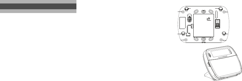
Wall Mounting Plate
1. Locate the screw holes (4) at each corner of the
mounting plate.
2. Use the four screws provided to affix the mount-
ing plate to the wall; ensure the mounting tabs
are facing you (see diagram below). If the keypad
is to be mounted on drywall, use plastic anchors
(not supplied).
3.Align the four mounting slots in the HS2LCDWF
housing with the four mounting tabs protruding
from the mounting plate.
4. Slide the keypad into place.
5. Firmly but carefully snap the keypad down onto
the mounting plate.
Desk Stand -
HS2LC-
DWFDMK
1. Insert the four rub-
ber feet (found in
the hardware pack)
into the indentations
provided in the bot-
tom of the desk
stand.
2. Place the desk stand on a secure, uncluttered sur-
face.
3.Align the four mounting slots in the HS2LCDWF
housing with the four mounting tabs protruding
from the desk stand.
4. Slide the keypad into place. Firmly but carefully
snap the keypad down onto the desk stand.
5. To fasten the keypad securely onto the desk
stand, locate the hole in the centre of the bottom
of the desk stand. Using the screws provided,
screw the keypad to the desk stand.
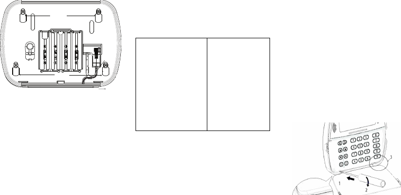
Apply Battery Power
1. Slide the keypad up and out from the mounting
plate/desk stand (removing the screws first if
required). The bay for the four AA batteries is
open and visible at the back of the keypad.
2. Insert the batteries as directed on the back of the
keypad. Ensure the correct polarity is observed.
3. Replace the keypad on the mounting plate/desk
stand.
Installation Instructions
• Temperature range: -10°C to +55°C (14°F to 131°F)
UL/ULC: 0°C to +49°C (32°F to 120°F)
• Humidity (MAX): 93%R.H. non-condensing
• Plastic enclosure protection degree: IP30, IK04
• Power adaptor output voltage: 9.0VDC @ 1.25A. Mod-
els - US/Latin America: xx; Canada: xx; EU: xx; UK:
xx; AUS./NZ: xx; China: xx limited power supply,
acceptable to the authority having jurisdiction
• Battery: 4 AA, 1.5 V, Energizer alkaline consumer-
grade
• Low Battery Indication: 4.3 V
• HS2LCDWF current draw: 50mA
• Wall-mount tamper
• 5 programmable function keys
• Ready (Green LED), Armed (Red LED), Trouble/RF
Jam (Red/Yellow LED), AC (Green LED)
• Frequency: 433.92MHz (xx only/xx only)
• Frequency: 868.35MHz (xx only)
• Frequency: 915MHz (xx only)
• Up to 128 wireless zones
NOTE: DSC recommends that the keypad be powered by
the AC adaptor and the batteries for EN installations.
When the power adaptor is used, batteries provide mini-
mum 24h back-up.
HS2LCDWF - wall mount HS2LCDWFP - prox tag
• 1 HS2LCDWF keypad • 1 HS2LCDWF keypad
• 1 HS2LCDWF wall
bracket
• 1 HS2LCDWF wall
bracket
• 1 Installation Manual • 1 Installation Manual
• 1 inner door sticker • 1 inner door sticker
• 4 AA batteries • 4 AA batteries
• 1 hardware pack • 1 hardware pack
• 1 prox tag
HS2LCDWFPV - prox
tag w/ verbal
annunciation
HS2LCDWFPV - prox
tag w/ verbal annuncia-
tion and transformer
• 1 HS2LCDWFBRK wall
bracket
• 1 HS2LCDWFBRK wall
bracket
• 1 Installation Manual • 1 Installation Manual
• 1 inner door sticker • 1 inner door sticker
• 1 power adaptor • 1 power adaptor
• 4 AA batteries • 4 AA batteries
• 2 hardware packs • 2 hardware packs
• 1 prox tag • 1 prox tag
• 1 transformer
HS2LCDWFPV - prox tag w/ verbal
annunciation, transformer and deskstand
• 1 HS2LCDWFBRK wall
bracket • 1 transformer
• 1 Installation Manual •1 HS2LCDWFDMK desk
stand
• 1 inner door sticker
• 1 power adaptor
• 4 AA batteries
• 2 hardware packs
• 1 prox tag
Screw hole
Screw hole
Screw hole
Screw hole
Mounting tab Mounting tab
Mounting tab Mounting tab
CAUTION: Do not mix old batteries with new ones.
Apply AC Power
1. Slide the keypad up and out from the mounting
plate / desk stand.
2. Locate the power adaptor jack at the back of the
keypad housing.
3. Place the adaptor plug in the housing indentation,
perpendicular to the keypad. Insert the adaptor
plug firmly into the jack.
4. Pivot the adaptor plug downwards so that it fits
flush with the housing. Guide the AC wire along
the channel provided in the keypad housing; the
wire will extend through the bottom of the hous-
ing.
5. Replace the keypad on the mounting plate/desk
stand (in the latter case, a further channel is pro-
vided in the bottom of the desk stand. Guide the
AC wire along this channel; the wire will extend
through an opening in the back of the stand).
6. Plug the adaptor into a wall outlet.
NOTE: Only use the power adaptor (4.5VDC, 0.5A, 2.25W,
limited power supply model XX) supplied with the kit.
CAUTION: The socket-outlet in which the direct plug-in
adaptor is inserted must be close to the keypad, easily
accessible, and have unobstructed access. The plug of the
adaptor serves as a means of disconnection from the sup-
ply mains.
Programming the Keypad
There are several programming options available for
the keypad (see below). Programming the keypad is
similar to programming the rest of the system. To
turn an option on/off, press the number correspond-
ing to the option on the number pad. The numbers of
the options that are currently turned on will be dis-
played along the top of the LCD. For information on
programming the rest of your security system, please
refer to your system’s Installation Manual.
Language Programming
To enter language programming, enter programming sec-
tion [000] then subsection [000]. Then enter the two-digit
number that corresponds to the language desired:
Enrolling the Keypad
The HSM2HOST wireless transceiver must be
enrolled onto the alarm panel before any wireless
devices can be enrolled.
When the alarm system is powered up for the first
time, the first keypad or the HSM2HOST (if using a
wireless keypad as the first keypad) can be enrolled.
To do this:
1. Once the HSM2HOST is wired to the alarm panel
and power has been applied, power up a wireless
keypad.
2. Press any button on the keypad to enroll it on the
HSM2HOST. The HSM2HOST is then automatically
enrolled on the alarm panel.
Enrolling Keypad
1. Enter [][8][Installer Code] and then section
[804] > 000.
2. When prompted, either activate the device to
enroll immediately or enter a device serial num-
ber. Do the latter to pre-enroll devices then enroll
them later at the customer site.
3. Use the scroll keys or type in the corresponding
number to select an option.
4. Scroll through the available selections, key in a
number or enter text as appropriate.
5. Press [*] to accept and move to the next option.
6. Once all options are configured, the system
prompts to enroll the next device.
7. Repeat the process described above until all wire-
less devices are enrolled.
Deleting Keypad
1. Enter [][8][Installer Code] and then section
[804] > 905.
2. Use the scroll keys to select the keypad or press
[#] to exit.
3. Select [*] to delete. The screen will read “Keypad
deleted”.
Disassemble Keypad
1. Insert the tip of a flat-head screwdriver into the
slot at the bottom left section of the keypad.
2. Gently lower the handle of the screwdriver, open-
ing the left side of the unit’s faceplate.
3. Repeat steps 1 and 2 using the slot at the bottom-
right section of the unit. This will remove the
unit’s faceplate and allow access for mounting.
Applying Battery Power
1. Slide the keypad up and out from the mounting
plate/desk stand (removing the screws first if
required). The bay for the four AA batteries is
open and visible at the back of the keypad.
2. Insert the batteries as directed on the back of the
keypad. Ensure the correct polarity is observed.
3. Replace the keypad on the mounting plate/desk
stand.
CAUTION: Do not mix old batteries with new ones.
Apply AC Power
1. Slide the keypad up and out from the mounting
plate/desk stand.
2. Locate the power adaptor jack at the back of the
keypad housing.
Plug
Mounting
Holes
Mounting
Holes
Wire
channel
01 = English (default)
02 = Spanish
03 = Portuguese
04 = French
05 = Italian
06 = Dutch
07 = Polish
08 = Czech
09 = Finnish
10 = German
11 = Swedish
12 = Norwegian
13 = Danish
14 = Hebrew
15 = Greek
16 = Turkish
17 = FFU
18 = Croatian
19 = Hungarian
20 = Romanian
21 = Russian
22 = Bulgarian
23 = Latvian
24 = Lithuanian
25 = Ukrainian
26 = Slovakian
27 = Serbian
28 = Estonian
29 = Slovenian
3. Place the adaptor plug in the housing indentation, perpendicular to the key-
pad. Insert the adaptor plug firmly into the jack.
4. Pivot the adaptor plug downwards so that it fits flush with the housing.
Guide the AC wire along the channel provided in the keypad housing; the
wire will extend through the bottom of the housing.
5. Replace the keypad on the mounting plate/desk stand (in the latter case, a
further channel is provided in the bottom of the desk stand. Guide the AC
wire along this channel; the wire will extend through an opening in the back
of the stand).
6. Plug the adaptor into a wall outlet.
NOTE: Only use the power adaptor (9.0VDC, 1.25A, 11.25W) supplied with the kit.
CAUTION: The socket-outlet in which the direct plug-in adaptor is inserted must be
close to the keypad and easily accessible. Never obstruct the access to the socket out-
let. The plug of the adaptor serves as a means of disconnection from the supply mains.
Programming Labels
1. Use this section to assign a meaningful name (e.g., Front Door, Hallway,
etc.) to each zone.
2. Enter Keypad Programming by pressing [][8][Installer Code][].
3. Enter the 3-digit section number for the label to be programmed.
4. Use the arrow keys (<>) to move the cursor underneath the letter to be
changed.
5. Press number key 1 through 9, corresponding to the letter you require. For
example, pressing number key 2 once will display the letter D; pressing it
again will display the letter E; pressing it a third time will display the letter
F, and so on.
6. When the required letter or number is displayed use the arrow keys (<>) to
scroll to the next letter.
7. When you are finished programming the Zone Label, press []. Scroll to
‘Save’ and press [] again.
8. Repeat Steps 3 through 7 until all Labels are programmed.
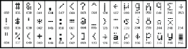
ASCII Characters
Label Library
The Label Library is a database of words commonly used when programming labels.
Individual words can be combined as needed. e.g., Front + Door. Each line of the dis-
play supports a maximum of 14 characters. If a word will not fit on a line, scroll right
until the cursor appears at the first character of the second line then add the word.
To program a custom label using the Label Library:
1. Enter keypad programming and select the label to change. e.g.,
[*][8][Installer Code][000][001] (to program the label for zone 01).
2. Press [*] to open the “Select Options” menu.
3. Press [*] again to select the “Words” option.
4. Enter the 3-digit number corresponding to a word (see Words table below)
or use the scroll keys [<][>] to view words in the library.
5. Press [*] to select the word.
6. To add another word, repeat the above procedure from step 2.
7. To add a space, press the right scroll key [>].
8. To clear characters, select “Clear to End” or “Clear Display” from the
“Select Options” menu.
9. To save the current label, press [*] to access the “Select Options” menu,
scroll left [<] to “Save” then press [*] again.
Broadcasting LCD Labels
If more than one LCD keypad is present on the system, labels programmed at
one keypad will be broadcast to all other LCD keypads right after the change is
confirmed.
Voice Prompt/Voice Chime
Voice Prompt Control (for wireless keypads only)
Menu: [*][6][access code] > Voice Control > Voice Prompt
Keypad: [*][6][access code]
This function is used to change the volume level of keypad voice prompts, for
example, “User arming in progress.” The voice prompt speaks the zone labels
programmed for zone openings/closings. Use the scroll keys (LCD/touchscreen
keypads) or the [*] key (LED/ICON keypads) to increase and decrease volume
or enter a value from 00 to 15. Selecting 00 turns off keypad voice prompts.
Voice Chime Control
Menu: [*][6][access code] > > Voice Control > Chime Control
Keypad: [*][6][access code]
This function is used to change the keypad voice chime volume level. Use the
scroll keys (LCD/touchscreen keypads) or the [*] key (LED/ICON keypads) to
increase and decrease voice chime volume or enter a value from 00 to 15.
Selecting 00 turns off voice chime.
NOTE: This feature is only available when the voice prompt feature is enabled.
Changing Brightness/Contrast/Buzzer/
LCD Keypads
1. Press [][6][Master Code].
2. Use the [<][>] keys to scroll to either Brightness/LED Bar Control, Contrast Con-
trol, Buzzer Control, or Voice Control.
3. Press [] to select the setting you want to adjust.
4. a) Brightness/LED Bar Control: There are 15 backlighting levels. Use the [<][>]
keys to scroll to the desired level. Changing this level adjusts the LED bar accord-
ingly.
b) Contrast Control: There are 15 different display contrast levels. Use the [<][>]
keys to scroll to the desired contrast level.
[1] - A, B, C, 1 [4] - J, K, L, 4 [7] - S, T, U, 7 [0] - Space
[2] - D, E, F, 2 [5] - M, N, O, 5 [8] - V, W, X, 8 [*] - Select
[3] - G, H, I, 3 [6] - P, Q, R, 6 [9] - Y, Z, 9,0 [#] - Escape
c) Buzzer Control: There are 15 different buzzer control levels. Use the [<][>] keys
to scroll to the desired contrast level.
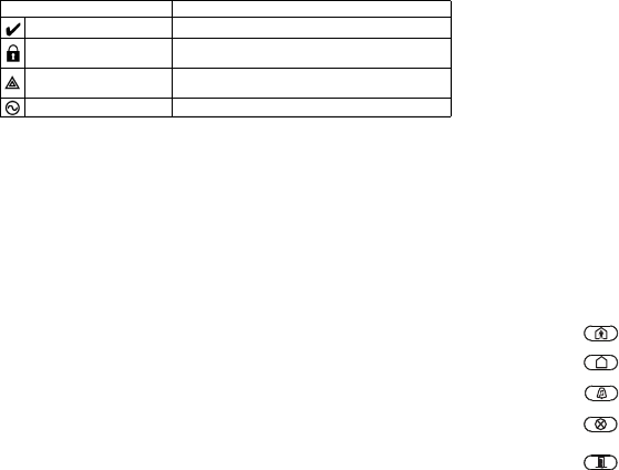
Keypad LED Symbols
Proximity Tags (HS2LCDWFP, HS2LCDWFPV only)
The proximity tag can be used to perform any keypad function that would nor-
mally require a user access code. The tag is to be presented to the face of the
keypad. While the keypad is running off AC, the transceiver is always on to
detect any prox tag approaching. While the keypad is running on battery and in
sleep mode, the user can press any key to wake the keypad, then present the
prox tag.
Enrolling Proximity Tags
Enrolling a tag on one keypad will enroll it automatically to all HS2LCDWFP
or HS2LCDWFPV keypads enrolled on the system.
1. Enter [][5] and an access code with the supervisor attribute enabled.
2. Select or enter a two-digit User Code slot (02-95) to be associated with the
proximity tag. Alternatively, scroll to the two-digit user number and press
the [] key.
3. Scroll to ‘Press [] for Prox Tag’ and press the [] key.
4. The screen will prompt “Present Your Prox Tag”; do so or press the [#] key
to exit.
5. Present your proximity tag to the keypad. If enrollment is successful,
acknowledgement beeps will sound and the keypad LCD will read ‘Tag
Enrolled Successfully’. If enrollment is unsuccessful, an error tone will
sound and the keypad will read ‘Invalid Tag Not Enrolled’. If the tag has
been enrolled previously, an error tone will sound.
Deleting Proximity Tags
Delete the prox tags from the system when they are lost or no longer needed.
1. Enter [][5] and an access code with the supervisor attribute enabled.
2. The keypad will display the user number and include the letter ‘T’ if a prox
tag is programmed.
3. Scroll to ‘Press [] for Prox Tag’ and press the [] key.
4. The keypad will read ‘Press [] To Delete Tag’.
5.After pressing [], the message ‘Tag Deleted Successfully’ appears.
NOTE: User codes can only be deleted individually.
NOTE: User 01 - Master Code cannot be deleted; a deletion attempt on this user code will
delete the proximity tag only.
NOTE: A user code, once deleted, must be re-enrolled before it can be used again.
Keypad Function Key Programming
To program a function key:
1. Enter Installer Programming by entering [][8][Installer Code].
2. Press [861] for keypad programming. Section [860] is read-only and shows
the slot number of the keypad being accessed.
3. Enter [001]-[005] for function keys 1-5.
4. Enter a 2-digit number to assign a function key operation - [00]-[68]. See
table below.
5. Continue from step 3 until all function keys are programmed.
6. Press the [#] key twice to exit Installer Programming.
[001]-[005] Function Key Assignment
Symbol Description
Ready Light (Green) If Ready light is ON, the system is ready to arm.
Armed Light (Red) If Armed light is ON/Flashing, the system has
been armed successfully.
System Trouble (Yellow) ON - Indicates that a system trouble is active.
Flashing - Keypad low battery.
AC (Green) ON - Indicates that AC is present at the keypad.
Section Function
Key Button Valid
Range Default Function
[001] 1 00 - 68 03 Stay Arm I_______I_______I
[002] 2 00 - 68 04 Away Arm I_______I_______I
[003] 3 00 - 68 01 Disarm I_______I_______I
[004] 4 00 - 68 52 [P] Key
Alarm I_______I_______I
[005] 5 00 - 68 16 Quick
Exit I_______I_______I
Keypad Function Keys
Please see your system installation manual for more details on the function key
options below.
Keypad Programming
Enter keypad programming by entering Installer Programming, then Section [861] to
[876], which apply to keypads 1-16.
[860] Keypad Slot Number
This is not for programming; the two-digit slot number is displayed for information
only.
[861]-[876] Keypad Programming Sections
[000] Address of Partition
Upon selecting [000], a 2-digit entry is required to assign the keypad to a partition.
Entering 00 assigns the keypad as global. Valid entries are 00-32. The default is 01.
[001]-[005] Function Key 1-5 Assignment
[011] Keypad Input/Output Programming
[012] Local PGM Output Pulse Activation Time
[021] First Keypad Options
[022] Second Keypad Options
[00] - Null [16] - Quick Exit [37]-[50] For Future Use
[01] - Disarm [17] - Arm Interior [51]- [A] Key Alarm
[02] - Instant Stay
Arm [18]-[20] - For Future Use [52] - [P] Key Alarm
[03] - Stay Arm [21] - Command Output 1 [53] - [92] For Future Use
[04] - Away Arm [22] - Command Output 2
[05] - [*][9] No-Entry
Arm [23] - Command Output 3
[06] - Chime ON/
OFF [24] - Command Output 4
[07] - System Test [25]-[28] - For Future Use
[08] - For Future Use [29] - Bypass Group
Recall
[09] - Night Arm [30] - Quick Bypass
[10] - For Future
Use [31] - For Future Use
[11] - Away Arm no
Entry [32] - For Future Use
[12] - Global Stay
Arm [33] - Bypass Recall
[13] - Global Away
Arm [34] - For Future Use
[14] - Global Dis-
arming [35] - For Future Use
[15] - For Future Use [36] - Reactivate Stay/
Away and Night Zones
Default
Zone or PGM
Number 00 I_____I_____I_____I
I_____I_____I Minutes (00-99)
I_____I_____I Seconds (00-99)
Default Opt. ON OFF
ON I_____I 1 Fire Key Enabled Fire Key Disabled
ON I_____I 2 Medical Key Enabled Medical Key Disabled
ON I_____I 3 Panic Key Enabled Panic Key Disabled
ON I_____I 4 Display Access Code
When Programming
Display X’s When Pro-
gramming Access
Codes
OFF I_____I 5 For Future Use For Future Use
OFF I_____I 6 For Future Use For Future Use
OFF I_____I 7 For Future Use For Future Use
OFF I_____I 8 For Future Use For Future Use
Default Opt. ON OFF
ON I_____I 1 Local Clock Display ON Local Clock Display
OFF
OFF I_____I 2 Local Clock Displays 24-hr
Time
Local Clock Displays
AM/PM
ON I_____I 3 Auto Alarm Scroll ON Auto Alarm Scroll OFF
OFF I_____I 4 For Future Use For Future Use
OFF I_____I 5 Power LED Enabled Power LED Disabled
[023] Third Keypad Options
[030] LCD Message
[031] Downloaded LCD Message Duration
Default: 000 I_____I_____I_____I (Valid entries are 000-255), 000=Unlimited Message
Display
This number represents the number of times the downloaded message must be
cleared before it is permanently removed. This message can be cleared by press-
ing any key.
[101]-[228] Door Chime for Zones 1-128
[999] Reset Keypad Programming to Factory Defaults
1. Enter Installer’s Code.
2. Press [] or 999.
Limited Warranty
Digital Security Controls (DSC) warrants that for a period of 12 months from the date of purchase, the product shall be free of
defects in materials and workmanship under normal use and that in fulfilment of any breach of such warranty, DSC shall, at its
option, repair or replace the defective equipment upon return of the equipment to its repair depot. This warranty applies only to
defects in parts and workmanship and not to damage incurred in shipping or handling, or damage due to causes beyond the control
of DSC such as lightning, excessive voltage, mechanical shock, water damage, or damage arising out of abuse, alteration or
improper application of the equipment. The foregoing warranty shall apply only to the original buyer, and is and shall be in lieu of
any and all other warranties, whether expressed or implied and of all other obligations or liabilities on the part of DSC. DSC neither
assumes responsibility for, nor authorizes any other person purporting to act on its behalf to modify or to change this warranty, nor
to assume for it any other warranty or liability concerning this product. In no event shall DSC be liable for any direct, indirect or
consequential damages, loss of anticipated profits, loss of time or any other losses incurred by the buyer in connection with the
purchase, installation or operation or failure of this product. WARNING: DSC recommends that the entire system be completely
tested on a regular basis. However, despite frequent testing, and due to, but not limited to, criminal tampering or electrical disrup-
tion, it is possible for this product to fail to perform as expected. Important Information: Changes or modifications not expressly
approved by DSC could void the user’s authority to operate this equipment.
EN50131-1 Grade 2, Class 2, EN50131-6 Type B
Important Information
: Changes/modifications not expressly approved by DSC could void the user’s authority to operate this
equipment.
IMPORTANT - READ CAREFULLY: DSC Software purchased with or without Products and Components is copyrighted and is
purchased under the following license terms:
• This End-User License Agreement (“EULA”) is a legal agreement between
You
(the company, individual or entity who
acquired the Software and any related Hardware) and
Digital Security Controls, a division of Tyco Safety Products Canada
Ltd.
(“DSC”), the manufacturer of the integrated security systems and the developer of the software and any related products
or components (“HARDWARE”) which You acquired.
• If the DSC software product (“SOFTWARE PRODUCT” or “SOFTWARE”) is intended to be accompanied by HARDWARE,
and is NOT accompanied by new HARDWARE, You may not use, copy or install the SOFTWARE PRODUCT. The SOFTWARE
PRODUCT includes computer software, and may include associated media, printed materials, and “online” or electronic doc-
umentation.
• Any software provided along with the SOFTWARE PRODUCT that is associated with a separate end-user license agreement
is licensed to You under the terms of that license agreement.
• By installing, copying, downloading, storing, accessing or otherwise using the SOFTWARE PRODUCT, You agree uncondi-
tionally to be bound by the terms of this EULA, even if this EULA is deemed to be a modification of any previous arrangement
or contract. If You do not agree to the terms of this EULA, DSC is unwilling to license the SOFTWARE PRODUCT to You, and
You have no right to use it.
SOFTWARE PRODUCT LICENSE
ON I_____I 6 Power LED Indicates AC
Present ON
Power LED Indicates
AC Present OFF
ON I_____I 7 Alarms Displayed While
Armed
Alarms Not Displayed
While Armed
OFF I_____I 8 Auto-Scroll Open Zones
ON
Auto-Scroll Open
Zones OFF
Default Opt. ON OFF
OFF I____I 1 Armed LED On in
Sleep Mode Armed LED Off in Sleep Mode
ON I____I 2 Keypad Status Shows
Stay Arm
Keypad Status Shows Stay/
Away Arm
OFF I____I 3 5th Terminal is Keypad
PGM Output
5th Terminal is Keypad Zone
Input
OFF I____I 4 For Future Use For Future Use
OFF I____I 5 For Future Use For Future Use
OFF I____I 6 For Future Use For Future Use
OFF I____I 7 Temperature Display
Enabled Temperature Display Disabled
OFF I____I 8 Low Temperature
Warning Enabled
Low Temperature Warning
Disabled
NOTE: Programming options indicated in GREY are required for systems compliant
with EN50131-1 and EN50131-3 standards. Section [023]: 1=OFF
I_____I_____I_____I_____I_____I_____I_____I_____I_____I_____I_____I_____I_____I_____I_____I_____|
I_____I_____I_____I_____I_____I_____I_____I_____I_____I_____I_____I_____I_____I_____I_____I_____|
[041] Indoor Temperature Zone Assignment
Default: 000 I_____I_____I_____I (Valid entries are 000-128)
[042] Outdoor Temperature Zone Assignment
Default: 000 I_____I_____I_____I ( V alid entries are 000-128)
The keypad can be programmed to make up to four different chime sounds for
individual zones. e.g. for Zone 1 enter Section [101], for Zone 2 enter Section
[102].
Default Opt.
ON I____I 1 6 beeps
OFF I____I 2 ‘Bing-Bing’ tone
OFF I____I 3 ‘Ding-Dong’ tone
OFF I____I 4 Alarm tone (4 second
duration)
OFF I____I 5 Zone name
OFF I____I 6-8 For future use

The SOFTWARE PRODUCT is protected by copyright laws and international copyright treaties, as well as other intellectual
property laws and treaties. The SOFTWARE PRODUCT is licensed, not sold.
1. GRANT OF LICENSE This EULA grants You the following rights:
(a) Software Installation and Use - For each license You acquire, You may have only one copy of the SOFTWARE PRODUCT
installed.
(b) Storage/Network Use - The SOFTWARE PRODUCT may not be installed, accessed, displayed, run, shared or used concurrently on
or from different computers, including a workstation, terminal or other digital electronic device (“Device”). In other words, if You have
several workstations, You will have to acquire a license for each workstation where the SOFTWARE will be used.
(c) Backup Copy - You may make back-up copies of the SOFTWARE PRODUCT, but You may only have one copy per license installed
at any given time. You may use the back-up copy solely for archival purposes. Except as expressly provided in this EULA, You may not
otherwise make copies of the SOFTWARE PRODUCT, including the printed materials accompanying the SOFTWARE.
2. DESCRIPTION OF OTHER RIGHTS AND LIMITATIONS
(a) Limitations on Reverse Engineering, Decompilation and Disassembly - You may not reverse engineer, decompile, or
disassemble the SOFTWARE PRODUCT, except and only to the extent that such activity is expressly permitted by applicable law
notwithstanding this limitation. You may not make any changes or modifications to the Software, without the written permission of an officer
of DSC. You may not remove any proprietary notices, marks or labels from the Software Product. You shall institute reasonable measures to
ensure compliance with the terms and conditions of this EULA.
(b)
Separation of Components
- The SOFTWARE PRODUCT is licensed as a single product. Its component parts may not
be separated for use on more than one HARDWARE unit.
(c)
Single INTEGRATED PRODUCT
- If You acquired this SOFTWARE with HARDWARE, then the SOFTWARE PRODUCT is
licensed with the HARDWARE as a single integrated product. In this case, the SOFTWARE PRODUCT may only be used with
the HARDWARE as set forth in this EULA.
(d)
Rental
- You may not rent, lease or lend the SOFTWARE PRODUCT. You may not make it available to others or post it on
a server or web site.
(e)
Software Product Transfer
- You may transfer all of Your rights under this EULA only as part of a permanent sale or
transfer of the HARDWARE, provided You retain no copies, You transfer all of the SOFTWARE PRODUCT (including all
component parts, the media and printed materials, any upgrades and this EULA), and provided the recipient agrees to the
terms of this EULA. If the SOFTWARE PRODUCT is an upgrade, any transfer must also include all prior versions of the
SOFTWARE PRODUCT.
(f)
Termination
- Without prejudice to any other rights, DSC may terminate this EULA if You fail to comply with the terms
and conditions of this EULA. In such event, You must destroy all copies of the SOFTWARE PRODUCT and all of its component
parts.
g)
Trademarks
- This EULA does not grant You any rights in connection with any trademarks or service marks of DSC or its
suppliers.
3. COPYRIGHT
- All title and intellectual property rights in and to the SOFTWARE PRODUCT (including but not limited to any
images, photographs, and text incorporated into the SOFTWARE PRODUCT), the accompanying printed materials, and any
copies of the SOFTWARE PRODUCT, are owned by DSC or its suppliers. You may not copy the printed materials
accompanying the SOFTWARE PRODUCT. All title and intellectual property rights in and to the content which may be
accessed through use of the SOFTWARE PRODUCT are the property of the respective content owner and may be protected by
applicable copyright or other intellectual property laws and treaties. This EULA grants You no rights to use such content. All
rights not expressly granted under this EULA are reserved by DSC and its suppliers.
4. EXPORT RESTRICTIONS
- You agree that You will not export or re-export the SOFTWARE PRODUCT to any country, person,
or entity subject to Canadian export restrictions.
5. CHOICE OF LAW
- This Software License Agreement is governed by the laws of the Province of Ontario, Canada.
6. ARBITRATION
- All disputes arising in connection with this Agreement shall be determined by final and binding arbitration in
accordance with the Arbitration Act, and the parties agree to be bound by the arbitrator’s decision. The place of arbitration shall
be Toronto, Canada, and the language of the arbitration shall be English.
7. LIMITED WARRANTY
(a) NO WARRANTY
- DSC PROVIDES THE SOFTWARE “AS IS” WITHOUT WARRANTY. DSC DOES NOT WARRANT THAT THE
SOFTWARE WILL MEET YOUR REQUIREMENTS OR THAT OPERATION OF THE SOFTWARE WILL BE UNINTERRUPTED OR
ERROR-FREE.
(b) CHANGES IN OPERATING ENVIRONMENT -
DSC shall not be responsible for problems caused by changes in the
operating characteristics of the HARDWARE, or for problems in the interaction of the SOFTWARE PRODUCT with non-DSC-
SOFTWARE or HARDWARE PRODUCTS.
(c) LIMITATION OF LIABILITY; WARRANTY REFLECTS ALLOCATION OF RISK - IN ANY EVENT, IF ANY STATUTE IMPLIES
WARRANTIES OR CONDITIONS NOT STATED IN THIS LICENSE AGREEMENT, DSC’S ENTIRE LIABILITY UNDER ANY PROVISION OF THIS
LICENSE AGREEMENT SHALL BE LIMITED TO THE GREATER OF THE AMOUNT ACTUALLY PAID BY YOU TO LICENSE THE SOFTWARE
PRODUCT AND FIVE CANADIAN DOLLARS (CAD$5.00). BECAUSE SOME JURISDICTIONS DO NOT ALLOW THE EXCLUSION OR
LIMITATION OF LIABILITY FOR CONSEQUENTIAL OR INCIDENTAL DAMAGES, THE ABOVE LIMITATION MAY NOT APPLY TO YOU.
(d) DISCLAIMER OF WARRANTIES - THIS WARRANTY CONTAINS THE ENTIRE WARRANTY AND SHALL BE IN LIEU OF ANY AND ALL
OTHER WARRANTIES, WHETHER EXPRESSED OR IMPLIED (INCLUDING ALL IMPLIED WARRANTIES OF MERCHANTABILITY OR FITNESS
FOR A PARTICULAR PURPOSE) AND OF ALL OTHER OBLIGATIONS OR LIABILITIES ON THE PART OF DSC. DSC MAKES NO OTHER
WARRANTIES. DSC NEITHER ASSUMES NOR AUTHORIZES ANY OTHER PERSON PURPORTING TO ACT ON ITS BEHALF TO MODIFY OR TO
CHANGE THIS WARRANTY, NOR TO ASSUME FOR IT ANY OTHER WARRANTY OR LIABILITY CONCERNING THIS SOFTWARE PRODUCT.
(e) EXCLUSIVE REMEDY AND LIMITATION OF WARRANTY - UNDER NO CIRCUMSTANCES SHALL DSC BE LIABLE FOR ANY
SPECIAL, INCIDENTAL, CONSEQUENTIAL OR INDIRECT DAMAGES BASED UPON BREACH OF WARRANTY, BREACH OF CONTRACT,
NEGLIGENCE, STRICT LIABILITY, OR ANY OTHER LEGAL THEORY. SUCH DAMAGES INCLUDE, BUT ARE NOT LIMITED TO, LOSS OF
PROFITS, LOSS OF THE SOFTWARE PRODUCT OR ANY ASSOCIATED EQUIPMENT, COST OF CAPITAL, COST OF SUBSTITUTE OR
REPLACEMENT EQUIPMENT, FACILITIES OR SERVICES, DOWN TIME, PURCHASERS TIME, THE CLAIMS OF THIRD PARTIES, INCLUDING
CUSTOMERS, AND INJURY TO PROPERTY.
WARNING: DSC recommends that the entire system be completely tested on a
regular basis. However, despite frequent testing, and due to, but not limited to, criminal tampering or electrical
disruption, it is possible for this SOFTWARE PRODUCT to fail to perform as expected.
FCC Compliance Statement
Caution: Changes or modifications not expressly approved by Digital Security Controls could void your authority to use this
equipment.
This equipment generates and uses radio frequency energy and if not installed and used properly, in strict accordance with the
manufacturer’s instructions, may cause interference to radio and television reception. It has been type tested and found to comply
with the limits for Class B device in accordance with the specifications in Subpart “B” of Part 15 of FCC Rules, which are designed
to provide reasonable protection against such interference in any residential installation. However, there is no guarantee that
interference will not occur in a particular installation. If this equipment does cause interference to television or radio reception, which
can be determined by turning the equipment off and on, the user is encouraged to try to correct the interference by one or more of
the following measures: (i) Re-orient the receiving antenna; (ii) increase the separation between the equipment and receiver; (iii)
connect the equipment into an outlet on a circuit different from that to which the receiver is connected. If necessary, the user should
consult the dealer or an experienced radio/television technician for additional suggestions. The user may find the following booklet
prepared by the FCC helpful: “How to Identify and Resolve Radio/Television Interference Problems”. This booklet is available from
the U.S. Government Printing Office, Washington, D.C. 20402, Stock # 004-000-00345-4.
This Class B digital apparatus complies with Canadian ICES-003.
Cet appareil numérique de la classe B est conforme à la norme NMB-003 du Canada. IC:160A-HS2LCDWF The term IC before the
radio certification number signifies that the Industry Canada technical specifications were met.
The trademarks, logos, and service marks displayed on this document are registered in the United States [or other countries]. Any
misuse of the trademarks is strictly prohibited and Tyco International Ltd. will aggressively enforce its intellectual property rights to
the fullest extent of the law, including pursuit of criminal prosecution wherever necessary. All trademarks not owned by Tyco
International Ltd. are the property of their respective owners, and are used with permission or allowed under applicable laws. Product
offerings and specifications are subject to change without notice. Actual products may vary from photos. Not all products include all
features. Availability varies by region; contact your sales representative.
©2013 Tyco International Ltd. and its Respective Companies. All Rights Reserved
• www.dsc.com • Tech. Support: 1-800-387-3630 (Canada, US), 905-760-3000 • Printed in Canada
+HUHE\ '6& GHFODUHV WKDW WKLV GHYLFH LV LQ FRPSOLDQFH ZLWK WKH HVVHQWLDO
UHTXLUHPHQWVDQGRWKHUUHOHYDQWSURYLVLRQVRI'LUHFWLYH(&
7KH FRPSOHWH 577( 'HFODUDWLRQ RI &RQIRUPLW\ FDQ EH IRXQG DW
KWWSZZZGVFFRPOLVWLQJVBLQGH[DVS[
&=( '6& MDNR Y¿UREFH SURKODģXMH ŀH WHQWR Y¿UREHN MH Y VRXODGX VH YģHPL
UHOHYDQWQ¯PLSRŀDGDYN\VPÝUQLFH(&
'$1'6&HUNO¨UHUKHUYHGDWGHQQHNRPSRQHQWHQRYHUKROGHUDOOHYLNWLJHNUDYVDPW
DQGUHEHVWHPPHOVHUJLWWLGLUHNWLY(&
'87 +LHUELM YHUNODDUW '6& GDW GLW WRHVWHO LQ RYHUHHQVWHPPLQJ LV PHW GH HLVHQ HQ
EHSDOLQJHQYDQULFKWOLMQ(&
),1'6&YDNXXWWDDODLWWHHQW¦\WW¦Y¦QGLUHNWLLYLQ(&ROHQQDLVHWYDDWLPXNVHW
)5( 3DU OD SU«VHQWH '6& G«FODUH TXH FH GLVSRVLWLI HVW FRQIRUPH DX[ H[LJHQFHV
HVVHQWLHOOHVHWDXWUHVVWLSXODWLRQVSHUWLQHQWHVGHOD'LUHFWLYH(&
*(5+LHUGXUFKHUNO¦UW'6&GD¡GLHVHV*HU¦WGHQHUIRUGHUOLFKHQ%HGLQJXQJHQXQG
9RUUDXVHW]XQJHQGHU5LFKWOLQLH(&HQWVSULFKW
*5(˂˜˞˱ˬ˲˭˞ˮ˹˪˱ˬ˯ˤ'6&ˡˤ˨˻˪ˢ˦ ˹˱˦ ˞˲˱˛ ˤ ˰˲˰˧ˢ˲˛ ˢ˜˪˞˦ ˰˺˩˳˶˪ˤ ˩ˢ ˱˦˯
ˬ˲˰˦˻ˡˤ˯˞˭˞˦˱˛˰ˢ˦˯˧˞˦˩ˢ˹˨ˢ˯˱˦˯˙˨˨ˢ˯˰˴ˢ˱˦˧˚˯˞˪˞˳ˬˮ˚˯˱ˤ˯ˍˡˤˠ˜˞˯(&
,7$ &RQ OD SUHVHQWH OD 'LJLWDO 6HFXULW\ &RQWUROV GLFKLDUD FKH TXHVWR SURGRWWR ª
FRQIRUPH DL UHTXLVLWL HVVHQ]LDOL HG DOWUH GLVSRVL]LRQL ULOHYDQWL UHODWLYH DOOD 'LUHWWLYD
&(
125'6&HUNO¨UHUDWGHQQHHQKHWHQHULVDPVYDUPHGGHJUXQQOHJJHQGHNUDYRJ
ºYULJHUHOHYDQWHNUDYLGLUHNWLY()
32/'6&RĝZLDGF]DľHXU]ÇG]HQLHMHVWZ]JRGQRĝFL]]DVDGQLF]\PLZ\PDJDQLDPL
RUD]SR]RVWDĄ\PLVWRVRZQ\PLSRVWDQRZLHQLDPL'\UHNW\Z\:(
3253RU HVWHPHLRD'6& GHFODUDTXHHVWHHTXLSDPHQWR HVW£HPFRQIRUPLGDGH
FRP RV UHTXLVLWRV HVVHQFLDLV H RXWUDV GHWHUPLQD©·HV UHOHYDQWHV GD 'LUHFWLYD
(&
63$3RU OD SUHVHQWH '6& GHFODUDTXH HVWH HTXLSR HVW£HQ FRQIRUPLGDG FRQ ORV
UHTXLVLWRVHVHQFLDOHV\RWURVUHTXLVLWRVUHOHYDQWHVGHOD'LUHFWLYD(&
6:('6&EHNU¦IWDUK¦UPHGDWW GHQQD DSSDUDW XSSI\OOHU GH Y¦VHQWOLJD NUDYHQRFK
DQGUDUHOHYDQWDEHVW¦PPHOVHUL'LUHNWLYHW(&

Label Library Words
Aborted Breezeway Detector Fence Interior Menu Porch Sliding 0 O
AC Building Dining Fire Intrusion Monoxide Power Smoke 1 P
Access Bus Disarmed First Invalid Mother’s Press Son’s 2 Q
Active Bypass Door Floor Is Motion Program Sound 3 R
Activity Bypassed Down Force Key No Progress South 4 S
Alarm Cabinet Download Foyer Kids North Quiet Special 5 T
All Cancelled Downstairs Freeze Kitchen Not Rear Stairs 6 U
AM Car Drawer Front Latchkey Now Receiver Stay 7 V
Area Carbon Driveway Furnace Laundry Number Report Sun 8 W
Arm Central Duct Gallery Left Off RF Supervisory 9 X
Armed Chime Duress Garage Level Office Right System A Y
Arming Closed East Gas Library OK Room Tamper B Z
Attic Closet Energy Glass Light On Safe Temperature C (Space)
Auxiliary Closing Enter Goodbye Lights Open Saver Test D ’ (Apostrophe)
Away Code Entry Gym Living Opening Schedule Time E - (Dash)
Baby Communicator Error Hallway Load Panic Screen To F _ (Underscore)
Back Computer Exercise Heat Loading Partition Second Touchpad G *
Bar Control Exit Hello Low Patio Sensor Trouble H #
Basement Date Exterior Help Lower Pet Service Unbypass I :
Bathroom Daughter’s Factory High Main Phone Shed Unit J /
Battery Degrees Failure Home Master Please Shock Up K ?
Bedroom Delay Family House Mat PM Shop West L
Bonus Den Father’s In Medical Police Side Window M
Bottom Desk Feature Install Memory Pool Siren Zone N