Tyco Safety Canada 143G4010 Cellular Alarm communicator User Manual 29009085R001 3G4010 V4 0 IM ENG
Digital Security Controls Ltd. Cellular Alarm communicator 29009085R001 3G4010 V4 0 IM ENG
UserManual.wiki
>
Tyco Safety Canada
>
143G4010 User Manual
User Manual
Navigation menu
Upload a User Manual
Namespaces
Wiki Guide
HTML
PDF
Info
Views
User Manual
Discussion / Help
Navigation
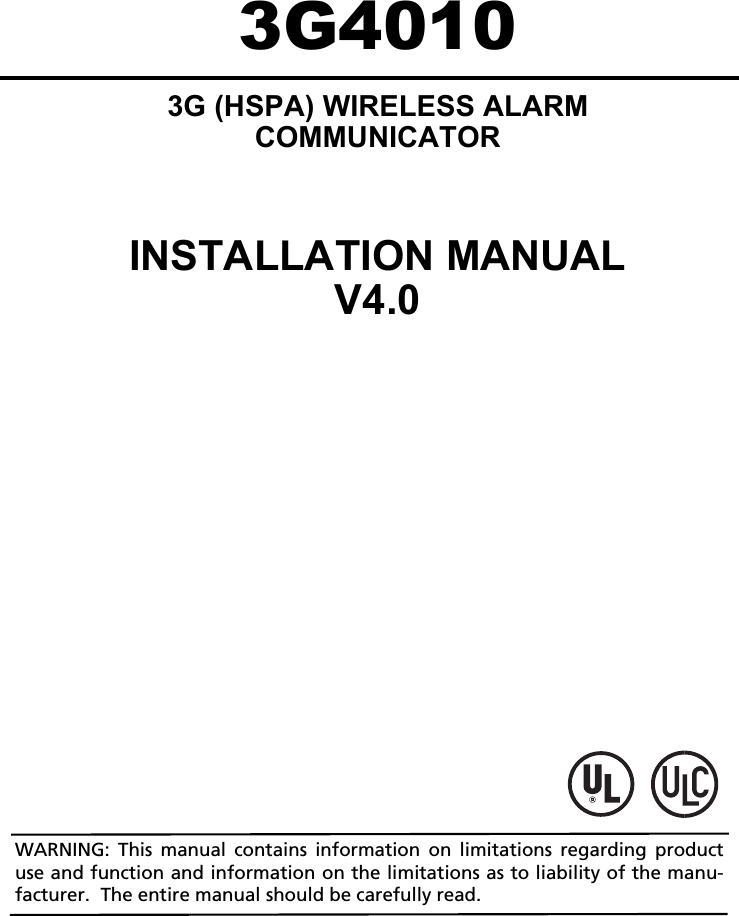
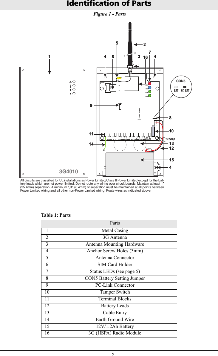
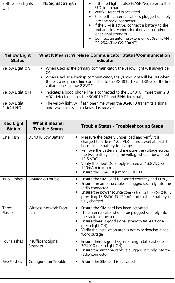
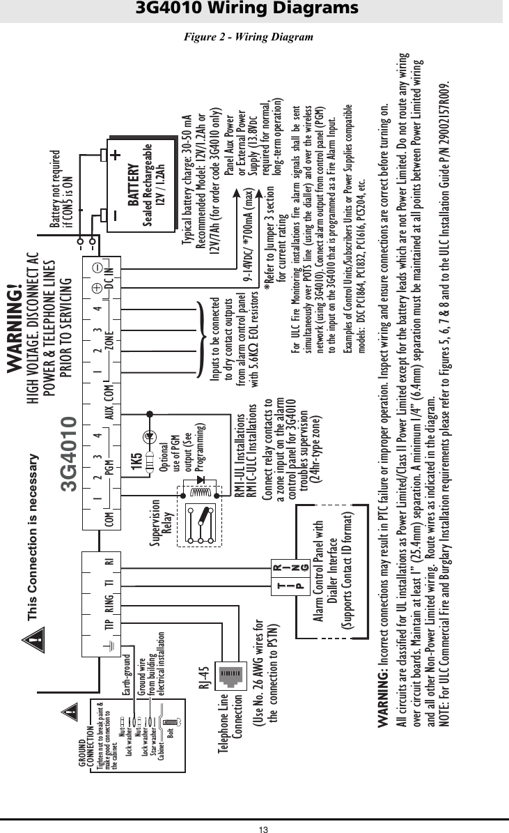
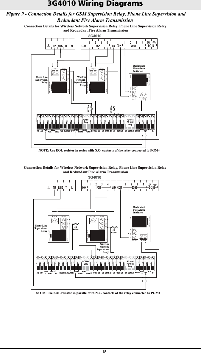
![Installing the 3G40104CONNECT 24 Enrolment InformationOnly authorized dealers can enrol a 3G4010 with CONNECT 24. Dealer application forms and additional information on the CONNECT 24 Voice Response Unit (VRU) can be found at the CONNECT 24 website www.connect24.com. Please contact CONNECT 24 at the number below for assistance:USA 1-888-251-7458 CANADA 1-888-955-5583NOTE: Step 1 should be performed before turning on the 3G4010 unit.NOTE: Before inserting or removing the SIM card, please ensure the unit is turned off.STEP 1 - Initialize the 3G4010 with Connect 24VRU EnrolmentCall the VRU at the toll-free number: 1-866-910-3865. Follow the voice prompts and enter your profile number, installer ID number, installer PIN number and SIM number. Ensure that all information is available and at hand before calling the VRU. It is recommended that the radio initialization be performed at least 24 hours in advance of installation to ensure SIM activation will be complete.WEB EnrolmentIf you have credentials for www.connect24.com, you may also initialize the 3G4010 via the web. Please check with your Connect 24 Master Reseller or Connect 24 Customer Service for more details.STEP 2 - Determine the Best Signal Location1. Unscrew the four screws securing the front panel to the cabinet. Remove the front panel.2. Fit the 3G antenna [2]. Ensure the 3G antenna mounting hardware is fastened securely [3].3. Attach the 3G radio module with the 3G antenna connector. Ensure that the connector is secure.4. Turn on the 3G4010 and check the signal strength.4.1 Connect the battery to the RED and BLK battery leads.4.2 Connect the DC power source to +/- 12V terminals.5. Allow the unit to power up.NOTE: The green LEDs will indicate the signal strength. The bottom green LED must be ON for the location to be acceptable. Please refer to the ‘Status LEDs’ section for more information.6. Power down the 3G4010 by removing the DC power source and battery leads. STEP 3 - Connect the 3G4010 1. Using the cabinet, mark the four screw locations. Drill the anchor screw holes. NOTE: Check for cable conduits and water pipes before drilling.2. Using anchor screws (not provided), mount the cabinet to the wall.3. Run the cables through the cable entry [13] or through the cabinet knockouts.4. Complete the connections on the terminal blocks [11]. NOTE: Ensure that power and Telco circuit connections are made only after the cabinet has been secured to the building or structure, and has been connected to the protective earth ground. Descriptions of the terminals can be found in the ‘Connecting the 3G4010’ section.5. Reattach the front cover [1] securely to the cabinet. Connecting the 3G4010NOTE: Please refer to Figure 2 at the end of this manual for wiring diagram.(1) Earth Ground - This terminal must be connected to the Mains Earth, in order to comply with the Telecommunications Network Safety Standards (Overvoltage Protection Requirements).TIP (2) / RNG (3) External Telephone Line - These terminals must be connected directly to the incoming telephone line.T1 (4) / R1 (5) Internal Telephone Line - These terminals must be connected to the TIP and RING of the control panel.COM (6,14) Common - This terminal is connected internally to Power Ground.PGM1 (7), PGM2 (8), PGM3 (9), PGM4 (10) Programmable Open-collector Outputs - These outputs can be activated by programmed events. Refer to ‘Activating the Outputs’ for details. The maximum current sink of each output must not exceed 50mA. AUX+ (11) Auxiliary 12V Output - +12V Output, 200mA PTC Protected.NOTE: Electrical current drawn from this terminal is drawn directly from the power supply. This](https://usermanual.wiki/Tyco-Safety-Canada/143G4010/User-Guide-2431085-Page-7.png)
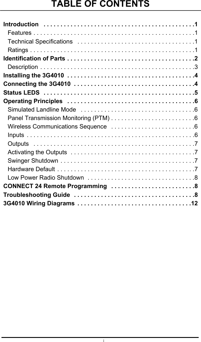
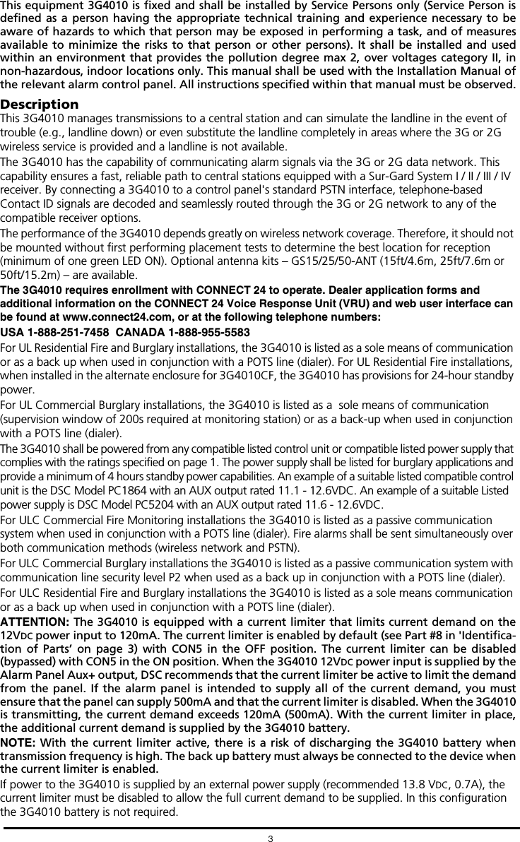
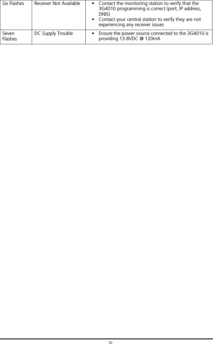
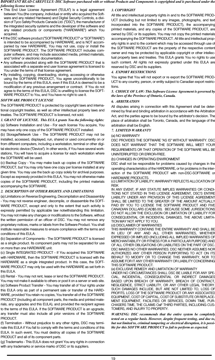
![5must be added to the 3G4010 current when determining the total draw on the host panel or power supply. Jumper CON5 does not limit the electrical current available on this output.Tamper (12-13) - These terminals are connected in series to the Tamper switch [10]. They will close when the cabinet is properly closed, and will open when the front cover is removed.Z1-Z4 (15-16-17-18) Programmable Inputs - These terminals can be set up to trigger events. Refer to ‘Inputs’ for details.12V (19), COM (20) Device Power Supply - These terminals must be connected to a rated power supply. Once the connections are completed, connect the battery leads (Red and Black wires, [12] in Figure 1) to a 12V, 7Ah battery.Jumper CON5CON5 ON - Full power, including standby capacity, comes from the host panel or external power supply. Supply must be capable of up to 700mA. The 3G4010 battery must not be connected.CON5 OFF - Current limiting mode, the host panel or external supply provides standby current. Supply must be capable of 120mA plus any current drawn from AUX+ terminal. 3G4010 battery must be installed for proper operation.Status LEDsNOTE: The power supply must have a minimum voltage of 13.5V to ensure a sufficient battery charge. An example of a suitable power supply is the DSC Model ADP1310-NA with DC output rated 13.8 VDC, 1Amp. This is to be used in conjunction with a 12V/7Ah rated battery for UL/ULC listed residential installations.NOTE: This mode of operation must not be used for ULC Listed Fire Monitoring installations.NOTE: When disposing of batteries, follow the instructions and precautions printed on the bat-teries, and contact your municipal offices for information on the disposal of used batteries.The 3G4010 interface has four status LEDs. The following describes the control panel status LEDs.NOTE: The top two LEDs blink during the Initializing and Programming phases. RED - This LED is normally Off; but, it will flash in the event of a trouble. This LED will switch on within three minutes in the event of wireless Module [16] trouble, or when the wireless Network is unavailable, ‘No Service’. If this LED flashes, the following list indicates the specific trouble based on the number of flashes, by priority. When turned on, the 3G4010 checks for the trouble conditions to be restored in the order listed below. The 3G4010 indicates the status of the highest priority, unrestored trouble condition with the corresponding number of flashes of the red LED. Once the highest priority trouble condition has been cleared, the next highest priority trouble condition is displayed (if applicable).1 flash - Battery Trouble (Battery with low voltage output)2 flashes - Radio/SIM Trouble (Battery absent or SIM Card disconnected)3 flashes - Wireless Network Problem (SIM not active, poor signal strength, antenna not connected)4 flashes - Insufficient Signal Strength (poor location)5 flashes - Connect 24 Configuration SMS Trouble (Improper VRU programming. Once the configu-ration is ready, turn off power for 2-3 seconds to allow the unit to restart and request again)6 flashes - Receiver not available (Improper VRU programming, receiver absent)7 flashes - Power Supply Trouble (DC power supply absent)Off - No TroublesYELLOW - When this LED is On (solid), a Phone Line Trouble condition exists. This LED switches on when the interface switches to the Wireless Network (due to a Landline trouble condition). This LED flashes slowly in the event of an incoming or outgoing voice call (regardless of the operating status of the landline). This LED can also flash quickly once (Wireless TX) or twice (Wireless RX).GREEN (Top) - When this LED is On, the reception is optimal. This LED switches On only when the other Green LED is on.GREEN (Bottom) - If this LED is Off and the Red LED is On, the Wireless Network service is unavailable (NO SERVICE). This LED flashes when the Wireless Network reception is poor. If this LED is on, the 3G4010 is able to communicate with the 3G (HSPA) or 2G (GPRS) network.](https://usermanual.wiki/Tyco-Safety-Canada/143G4010/User-Guide-2431085-Page-8.png)
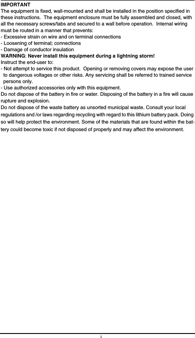
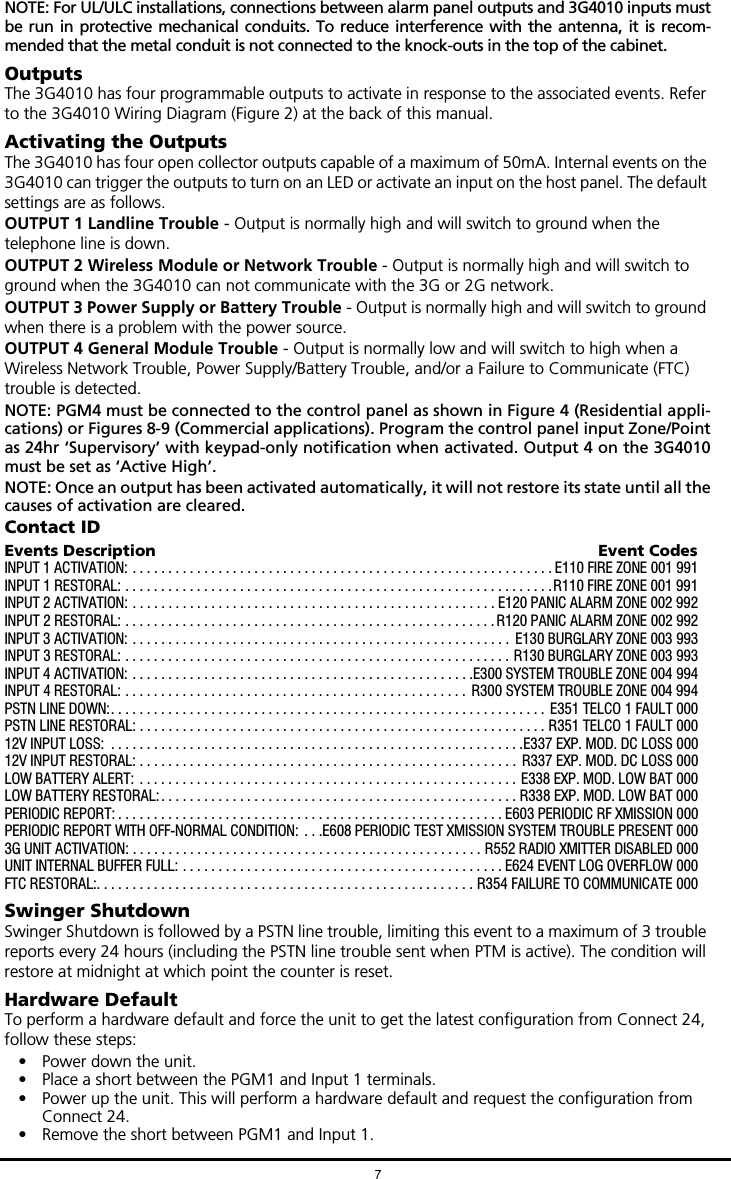
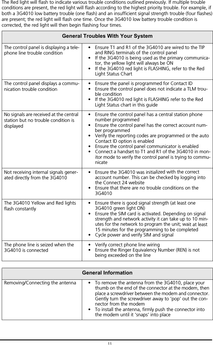
![Operating Principles6Simulated Landline ModeThe simulated landline provides the alarm control panel (with dialer interface) with a back up line in the event of PSTN line trouble. If the voltage on the landline terminals (TIP/RNG) drops below 2.8V for a period of between 10 seconds and 45 seconds - depending on the device connected to the T1/R1 terminals- the 3G4010 switches the connected telephone device to the wireless network. After waiting between 30 and 40 seconds, it checks the landline for one of the following:• If the landline has been restored, the 3G4010 switches the connected device back to the landline, OR• If the landline is still down, the 3G4010 continues the simulation until the landline is restored. The 3G4010 will not switch during ongoing calls.NOTE: When the landline is down, the 3G4010 provides a dial tone to any device connected to T1 and R1, including any telephones on the premises. The phones on the premises will not, how-ever, be able to dial out over the 3G4010.Panel Transmission Monitoring (PTM)The 3G4010 can also monitor the panel’s attempt to communicate with the central station. If it determines that the panel is having difficulty, it switches the line to the wireless network. This feature is only active when the 3G4010 is configured as a back up communicator. This feature is in addition to the regular line voltage detection.The 3G4010 monitors the phone line for four consecutive failed attempts within a 12-minute window. A failed attempt is assumed to have occurred when a line seizure takes place during dialing (either the alarm panel or the customer telephone), but no 1400Hz tone (or Contact Kiss-off) is sent from the receiver.Once the conditions for a failed attempt are met, the 3G4010 connects the panel to the wireless network to communicate the events. When the 3G4010 switches the line it stays in this mode until the panel hangs up. On the next event the 3G4010 restarts the error detection sequence before switching.The 3G4010 performs this sequence on any phone number that is detected on the line. Specific central station phone numbers can be programmed into the 3G4010 if desired. Up to four, 20-digit numbers can be added to your profile at Connect 24. If programmed, the 3G4010 will only look for Contact ID Kiss-off after these numbers are dialed. A Telephone Line Monitoring trouble (PGM output activation and/or reporting code if applicable) is also activated and/or transmitted when the PTM is activated. A restoral is sent at the end of the call.Wireless Communications Sequence• When an alarm is triggered, the control panel goes off-hook.• The 3G4010 asserts a dial tone.• The Control panel dials the number of the central station. Ensure that the alarm panel inserts a minimum one second pause, or has Dial Tone Search enabled before dialing the number.• The 3G4010 detects the DTMF dialing and stops dial tone.NOTE: The 3G4010 is unable to decode pulse dialing.• The 3G4010 sends the required Contact ID dual-tone handshake to the panel.• After receiving the handshake, the control panel transmits an alarm message in Contact ID format.• The 3G4010 decodes and transforms the Contact ID digits into an IP packet and sends it to the central station receiver over the wireless network.• The central station receiver acknowledges the alarm and sends a command to the 3G4010 to gen-erate the corresponding 1400Hz Kiss-off signal for a minimum of 800msec.After the 3G4010 generates a Kiss-off signal, it sends the next alarm or, if no further alarms need to be sent, the control panel goes on-hook.InputsThe 3G4010 has four inputs that can be used to trigger specific communications. These events will transmit using Contact ID format with Inputs 1-4 reporting as [991] to [994] respectively. Default settings are:INPUT 1- FIRE INPUT 3 - BURGLARYINPUT 2 - PANIC ALARM INPUT 4 - SYSTEM TROUBLEThese inputs are normally open and will activate when a short condition is detected between the terminal and the COM. Refer to the 3G4010 Wiring Diagram (Figure 2) at the back of this manual.NOTE: These inputs communicate using Contact ID format.](https://usermanual.wiki/Tyco-Safety-Canada/143G4010/User-Guide-2431085-Page-9.png)
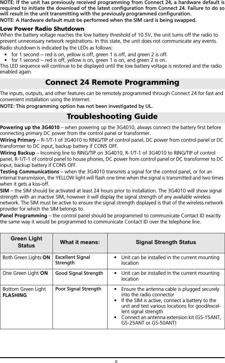
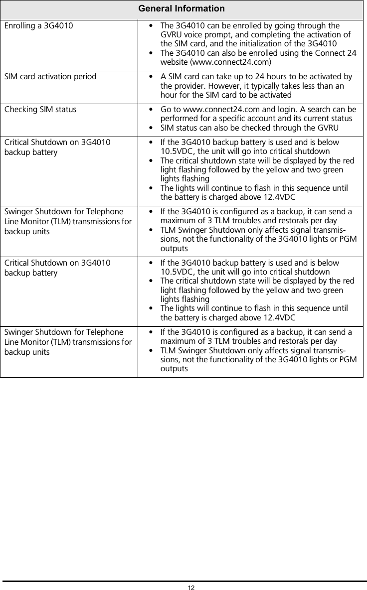
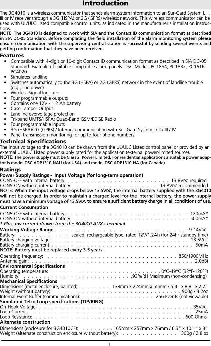
![3G4010 Wiring Diagrams15 Figure 5 - Fire Alarm Control Unit and 3G TransmitterWiring Diagram for Fire Alarm Control Unit (with dialler) and 3G (HSPA/2G (GPRS) Transmitter (Passive Communication System) AUX Power (12V/700mA) RM1C ULC Relay Fire Alarm Control Unit TIP/RING Zone Input Outputs FireTrouble 3G WirelessTransmitter 3G4010T1/R1 TIP/RINGZone PGM4Inputs Output 3G4010 cabinet 3G (HSPA) or2G (GPRS)AC Input NOTES:- Power for 3G4010 shall be provided from Fire Alarm Control Unit or separately Listed power supply rated for the application, 12V/700mA (Jumper CON5shall be set to on for Fire Monitoring). - All wiring connections must be run in a protective conduit. - For local supervision of the wireless transmitter connect PGM output from 3G4010 to one zone input on the Fire Alarm Control Unit. - Dry Contact Trouble output from ULC Listed Fire Alarm Control Unit must be connected to zone input on the 3G4010 for supervision of Tip/Ring connection. - Fire Alarms must be sent over both communication channels. Fire output from Fire Alarm Control Unit must be connected to the Input 1 on the 3G4010. - 24h Test Transmission must be enabled on the dialler and on the 3G4010. PSTN Figure 6 - DSC Subscribers’ Unit Fire and 3G Transmitter Mounted in the Same RoomWiring Diagram for DSC Subscribers’ Unit Fire and 3G Transmitter(Passive Communication System) Fire Alarm Control Unit Outputs FireSupervisory Trouble DSCSubscribers’ Unit FireZoneInputs TIP TIP RING PGM1 DSC Keypad LCD4501 PK55XX3G WirelessTransmitter 3G4010T1/R1 TIP/RING Zone Input PGM4 AUX Power 12V/700mA RM1C ULC Relay PC5003CPC4050CRcabinet3G (HSPA)/2G (GPRS) PSTNAC Input AC Input NOTES:- Power for 3G4010 must be provided from Fire Alarm Control Unit or separately listed power supply rated for the application (12V/700mA) (Jumper CON5 shall be on for Fire Monitoring).- All wiring connections must be run in a protective conduit.- Phone Line Monitoring (TLM) must be enabled. - Connect PGM4 output from 3G4010 (Trouble Conditions) to a zone input on the Subscriber Unit for supervision of the GSM Transmitter. - 24hr Test Transmission over phone line (PSTN) and 3G4010 must be enabled. - Fire Alarms must be sent over both communication channels. - On the Subscribers’ Unit, program PGM1 for PC1616/PC1832/PC1864 as System Event (Section [009] as type 10; Section [501] Fire Event option 2 ON). An alternate option is to program PGM1 as ZoneFollower (Sec [009] = 29) and assign Fire Zone to PGM1in Section [551]. Ensure Bit 3 is on in [501]. In this case,a restored fire alarm condition does not require the DSCcontrol panel to be reset.For PC4020 program PGM1 as type 49 Steady Fire ([00070049]). - Dry contact outputs from ULC Listed Fire Alarm Control Unit must be connected to zone inputs on the ULC Listed DSC Subscribers’ Unit Fire. PC4020 PC1864 PC1832 PC1616RM1C ULC Relay 3G4010 cabinet - Phone Line trouble is indicated by Yellow LED on 3G4010. - Refer to detailed diagrams in Figure 7.](https://usermanual.wiki/Tyco-Safety-Canada/143G4010/User-Guide-2431085-Page-18.png)
![Tech Support: 1-800-387-3630 (Canada & US) or 905-760-30000 - www.dsc.com29009085R001© 2014 Tyco International Ltd. and its Respective Companies. All Rights Reserved.The trademarks, logos, and service marks displayed on this document are registered in the United States [or other countries]. Any misuse of the trademarks is strictly prohibited and Tyco International Ltd. will aggressively enforce its intellectual property rights to the fullest extent of the law, including pursuit of criminal prosecution wherever necessary. All trademarks not owned by Tyco International Ltd. are the property of their respective owners, and are used with permission or allowed under applicable laws. Product offerings and specifications are subject to change without notice. Actual products may vary from photos. Not all products include all features. Availability varies by region; contact your sales representative.Limited WarrantyDigital Security Controls warrants the original purchaser that for a period of twelve months from the date of purchase, the product shall be free of defects in materials and workmanship under normal use. During the warranty period, Digital Security Controls shall, at its option, repair or replace any defective product upon return of the prod-uct to its factory, at no charge for labour and materials. Any replacement and/or repaired parts are warranted for the remainder of the original warranty or ninety (90) days, whichever is longer. The original purchaser must promptly notify Digital Security Controls in writing that there is defect in material or workmanship, such written notice to be received in all events prior to expiration of the warranty period. There is absolutely no warranty on software and all software products are sold as a user license under the terms of the software license agree-ment included with the product. The Customer assumes all responsibility for the proper selection, installation, operation and maintenance of any products purchased from DSC. Custom products are only warranted to the extent that they do not function upon delivery. In such cases, DSC can replace or credit at its option.International WarrantyThe warranty for international customers is the same as for any customer within Canada and the United States, with the exception that Digital Security Controls shall not be responsible for any customs fees, taxes, or VAT that may be due.Warranty ProcedureTo obtain service under this warranty, please return the item(s) in question to the point of purchase. All autho-rized distributors and dealers have a warranty program. Anyone returning goods to Digital Security Controls must first obtain an authorization number. Digital Security Controls will not accept any shipment whatsoever for which prior authorization has not been obtained.Conditions to Void WarrantyThis warranty applies only to defects in parts and work-manship relating to normal use. It does not cover:• damage incurred in shipping or handling;• damage caused by disaster such as fire, flood, wind, earthquake or lightning;• damage due to causes beyond the control of Digital Security Controls such as excessive voltage, mechanical shock or water damage;• damage caused by unauthorized attachment, alter-ations, modifications or foreign objects;• damage caused by peripherals (unless such peripherals were supplied by Digital Security Controls);• defects caused by failure to provide a suitable installa-tion environment for the products;• damage caused by use of the products for purposes other than those for which it was designed;• damage from improper maintenance;• damage arising out of any other abuse, mishandling or improper application of the products.Items Not Covered by WarrantyIn addition to the items which void the Warranty, the following items shall not be covered by Warranty: (i) freight cost to the repair centre; (ii) products which are not identified with DSC's product label and lot number or serial number; (iii) products disassembled or repaired in such a manner as to adversely affect performance or prevent adequate inspection or testing to verify any war-ranty claim. Access cards or tags returned for replace-ment under warranty will be credited or replaced at DSC's option. Products not covered by this warranty, or other-wise out of warranty due to age, misuse, or damage shall be evaluated, and a repair estimate shall be provided. No repair work will be performed until a valid purchase order is received from the Customer and a Return Merchandise Authorisation number (RMA) is issued by DSC's Customer Service.Digital Security Controls’ liability for failure to repair the product under this warranty after a reasonable number of attempts will be limited to a replacement of the product, as the exclusive remedy for breach of warranty. Under no circumstances shall Digital Security Controls be liable for any special, incidental, or consequential damages based upon breach of warranty, breach of contract, negligence, strict liability, or any other legal theory. Such damages include, but are not limited to, loss of profits, loss of the product or any associated equipment, cost of capital, cost of substitute or replacement equipment, facilities or ser-vices, down time, purchaser’s time, the claims of third parties, including customers, and injury to property. The laws of some jurisdictions limit or do not allow the dis-claimer of consequential damages. If the laws of such a jurisdiction apply to any claim by or against DSC, the limitations and disclaimers contained here shall be to the greatest extent permitted by law. Some states do not allow the exclusion or limitation of incidental or conse-quential damages, so that the above may not apply to you.Disclaimer of WarrantiesThis warranty contains the entire warranty and shall be in lieu of any and all other warranties, whether expressed or implied (including all implied warranties of merchantabil-ity or fitness for a particular purpose) and of all other obligations or liabilities on the part of Digital Security Controls Digital Security Controls neither assumes responsibility for nor authorizes any other person pur-porting to act on its behalf to modify or to change this warranty, nor to assume for it any other warranty or liability concerning this product.This disclaimer of warranties and limited warranty are governed by the laws of the province of Ontario, Canada.WARNING: Digital Security Controls recommends that the entire system be completely tested on a regular basis. However, despite frequent testing, and due to, but not limited to, criminal tampering or electrical disruption, it is possible for this product to fail to perform as expected.Out of Warranty RepairsDigital Security Controls will at its option repair or replace out-of-warranty products which are returned to its fac-tory according to the following conditions. Anyone returning goods to Digital Security Controls must first obtain an authorization number. Digital Security Controls will not accept any shipment whatsoever for which prior authorization has not been obtained.Products which Digital Security Controls determines to be repairable will be repaired and returned. A set fee which Digital Security Controls has predetermined and which may be revised from time to time, will be charged for each unit repaired.](https://usermanual.wiki/Tyco-Safety-Canada/143G4010/User-Guide-2431085-Page-24.png)