Tyco Safety Canada 143G4010 Cellular Alarm communicator User Manual 29009085R001 3G4010 V4 0 IM ENG
Digital Security Controls Ltd. Cellular Alarm communicator 29009085R001 3G4010 V4 0 IM ENG
User Manual

3G4010
3G (HSPA) WIRELESS ALARM
COMMUNICATOR
INSTALLATION MANUAL
V4.0
WARNING: This manual contains information on limitations regarding product
use and function and information on the limitations as to liability of the manu-
facturer. The entire manual should be carefully read.

i
Introduction . . . . . . . . . . . . . . . . . . . . . . . . . . . . . . . . . . . . . . . . . . . . .1
Features . . . . . . . . . . . . . . . . . . . . . . . . . . . . . . . . . . . . . . . . . . . . . . . .1
Technical Specifications . . . . . . . . . . . . . . . . . . . . . . . . . . . . . . . . . . .1
Ratings . . . . . . . . . . . . . . . . . . . . . . . . . . . . . . . . . . . . . . . . . . . . . . . . .1
Identification of Parts . . . . . . . . . . . . . . . . . . . . . . . . . . . . . . . . . . . . . .2
Description . . . . . . . . . . . . . . . . . . . . . . . . . . . . . . . . . . . . . . . . . . . . . .3
Installing the 3G4010 . . . . . . . . . . . . . . . . . . . . . . . . . . . . . . . . . . . . . .4
Connecting the 3G4010 . . . . . . . . . . . . . . . . . . . . . . . . . . . . . . . . . . . .4
Status LEDS . . . . . . . . . . . . . . . . . . . . . . . . . . . . . . . . . . . . . . . . . . . . .5
Operating Principles . . . . . . . . . . . . . . . . . . . . . . . . . . . . . . . . . . . . . .6
Simulated Landline Mode . . . . . . . . . . . . . . . . . . . . . . . . . . . . . . . . . .6
Panel Transmission Monitoring (PTM) . . . . . . . . . . . . . . . . . . . . . . . . .6
Wireless Communications Sequence . . . . . . . . . . . . . . . . . . . . . . . . .6
Inputs . . . . . . . . . . . . . . . . . . . . . . . . . . . . . . . . . . . . . . . . . . . . . . . . . .6
Outputs . . . . . . . . . . . . . . . . . . . . . . . . . . . . . . . . . . . . . . . . . . . . . . . .7
Activating the Outputs . . . . . . . . . . . . . . . . . . . . . . . . . . . . . . . . . . . . .7
Swinger Shutdown . . . . . . . . . . . . . . . . . . . . . . . . . . . . . . . . . . . . . . . .7
Hardware Default . . . . . . . . . . . . . . . . . . . . . . . . . . . . . . . . . . . . . . . . .7
Low Power Radio Shutdown . . . . . . . . . . . . . . . . . . . . . . . . . . . . . . . .8
CONNECT 24 Remote Programming . . . . . . . . . . . . . . . . . . . . . . . . .8
Troubleshooting Guide . . . . . . . . . . . . . . . . . . . . . . . . . . . . . . . . . . . .8
3G4010 Wiring Diagrams . . . . . . . . . . . . . . . . . . . . . . . . . . . . . . . . . .12
TABLE OF CONTENTS

ii
IMPORTANT
The equipment is fixed, wall-mounted and shall be installed in the position specified in
these instructions. The equipment enclosure must be fully assembled and closed, with
all the necessary screws/tabs and secured to a wall before operation. Internal wiring
must be routed in a manner that prevents:
- Excessive strain on wire and on terminal connections
- Loosening of terminal; connections
- Damage of conductor insulation
WARNING: Never install this equipment during a lightning storm!
Instruct the end-user to:
- Not attempt to service this product. Opening or removing covers may expose the user
to dangerous voltages or other risks. Any servicing shall be referred to trained service
persons only.
- Use authorized accessories only with this equipment.
Do not dispose of the battery in fire or water. Disposing of the battery in a fire will cause
rupture and explosion.
Do not dispose of the waste battery as unsorted municipal waste. Consult your local
regulations and /or laws regarding recycling with regard to this lithium battery pack. Doing
so will help protect the environment. Some of the materials that are found within the bat-
tery could become toxic if not disposed of properly and may affect the environment.

Introduction
1
The 3G4010 is a wireless communicator that sends alarm system information to an Sur-Gard System I, II,
III or IV receiver through a 3G (HSPA) or 2G (GPRS) wireless network. This wireless communicator can be
used with UL/ULC Listed compatible control units, as indicated in the manufacturer's installation instruc-
tions.
NOTE: The 3G4010 is designed to work with SIA and the Contact ID communication format as described
in SIA DC-05 Standard. Before completing the field installation of the alarm monitoring system please
ensure communication with the supervising central station is successful by sending several events and
getting confirmation that they have been received.
Features
• Compatible with 4-digit or 10-digit Contact ID communication format as described in SIA DC-05
Standard. Example of suitable compatible alarm panels: DSC Models PC1864, PC1832, PC1616,
PC4020.
• Simulates landline
• Switches automatically to the 3G (HSPA) or 2G (GPRS) network in the event of landline trouble
(e.g., line down)
• Wireless Signal Indicator
• Four programmable outputs
• Contains one 12V - 1.2 Ah battery
• Case Tamper Output
• Landline overvoltage protection
• Tri-band UMTS/HSPA; Quad-Band GSM/EDGE Radio
• Four programmable inputs
• 3G (HSPA)/2G (GPRS) / Internet communication with Sur-Gard System I / II / III / IV
• Panel transmission monitoring for up to four phone numbers
Technical Specifications
The input voltage to the 3G4010 can be drawn from the UL/ULC Listed control panel or provided by an
external UL/ULC Listed power supply rated for the application (external power-limited source).
NOTE: The power supply must be Class 2, Power Limited. For residential applications a suitable power adap-
tor is model DSC ADP1310-NAU (for USA) and model DSC ADP1310-NA (for Canada).
Ratings
Power Supply Ratings - Input Voltage (for long-term operation)
CON5-OFF with internal battery: . . . . . . . . . . . . . . . . . . . . . . . . . . 13.8VDC required
CON5-ON without internal battery: . . . . . . . . . . . . . . . . . . . . . 13.8VDC recommended
NOTE: When the input voltage drops below 13.5V
DC
, the internal battery supplied with the 3G4010
will not be charged. In order to maintain a charged level for the internal battery, the power supply
must have a minimum voltage of 13.5V
DC
to ensure a sufficient battery charge in all conditions of use.
Current Consumption
CON5-OFF with internal battery: . . . . . . . . . . . . . . . . . . . . . . . . . . . . . . . 120mA*
CON5-ON without internal battery: . . . . . . . . . . . . . . . . . . . . . . . . . . . . . 500mA*
* Plus any current drawn from the 3G4010 AUX+ terminal
Working Voltage Range . . . . . . . . . . . . . . . . . . . . . . . . . . . . . . . . . . 9-14VDC
Battery: . . . . . . . . . . . . . sealed, rechargeable type, rated 12V/1.2Ah (for 24hr standby time)
Battery charging voltage: . . . . . . . . . . . . . . . . . . . . . . . . . . . . . . . . . . . 13.5VDC
Battery charging current: . . . . . . . . . . . . . . . . . . . . . . . . . . . . . . . . . . . . 50mA
NOTE: Battery must be replaced every 3-5 years.
Operating frequency: . . . . . . . . . . . . . . . . . . . . . . . . . . . . . . . . . 850/1900MHz
Antenna gain: . . . . . . . . . . . . . . . . . . . . . . . . . . . . . . . . . . . . . . . . . 2.0dBi
Environmental Specifications
Operating temperature: . . . . . . . . . . . . . . . . . . . . . . . . . . . . 0°C-49°C (32°F-120°F)
Humidity: . . . . . . . . . . . . . . . . . . . . . . . . . . . .93%RH Maximum (non-condensing)
Mechanical Specifications
Dimensions (metal enclosure, painted): . . . . . . . . 138mm x 224mm x 55mm / 5.4” x 8.8” x 2.2”
Weight (without battery): . . . . . . . . . . . . . . . . . . . . . . . . . . . . . . . . 900g / 3.2oz
Internal Event Buffer (communications): . . . . . . . . . . . . . . . . . . 256 Events (not viewable)
Simulated Telco Loop specifications (TIP/RING)
On-Hook Voltage: . . . . . . . . . . . . . . . . . . . . . . . . . . . . . . . . . . . . . . . 35VDC
Loop Current . . . . . . . . . . . . . . . . . . . . . . . . . . . . . . . . . . . . . . . . . . 25mA
Loop Resistance . . . . . . . . . . . . . . . . . . . . . . . . . . . . . . . . . . . . . . 600 Ohms
Alternate construction
Dimensions (enclosure for 3G4010CF): . . . . . . . . 165mm x 257mm x 76mm / 6.3” x 10.1” x 3”
Weight (alternate construction enclosure without battery): . . . . . . . . . . . . . . 1300g / 2.8lbs
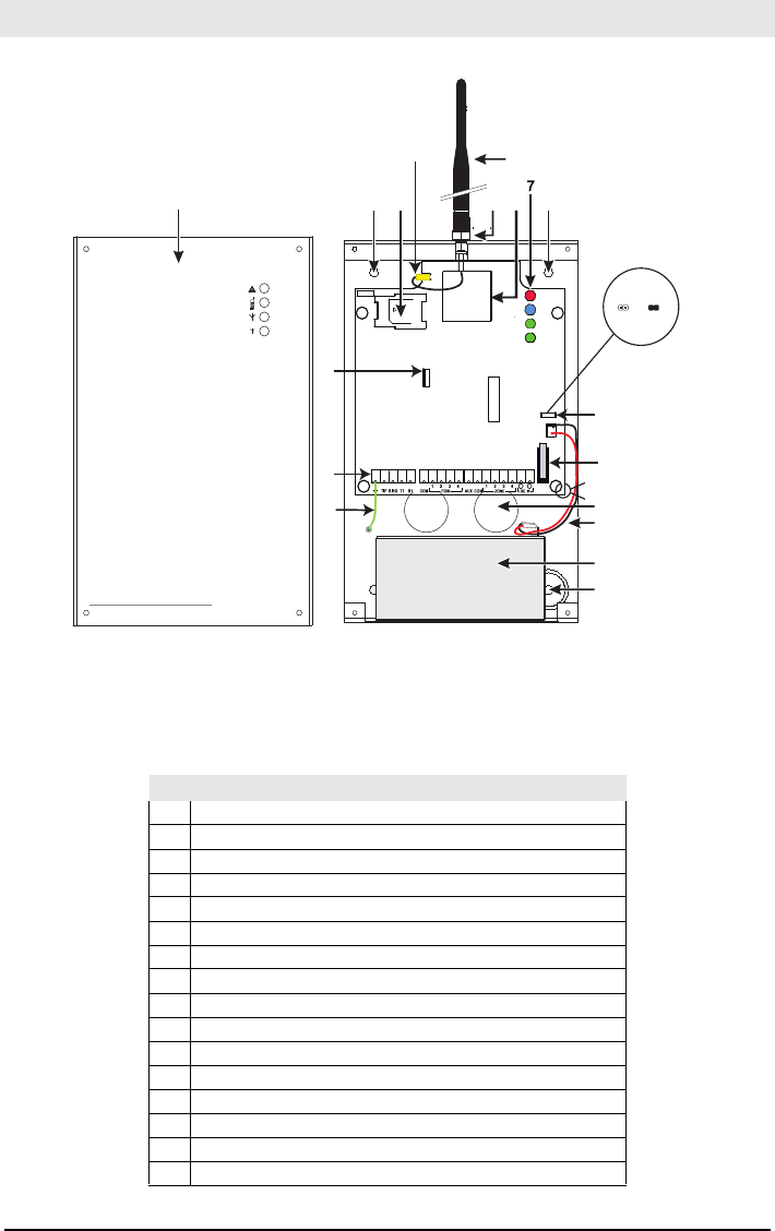
Identification of Parts
2
Figure 1 - Parts
CON3
LE D2
BAT+
NO
OPEN
+
LE D1
BAT-
-
LE D4
LE D3
BA T
BA T
UA673
SERIAL N UMB ER
144
5
3
2
16
6
9
10
8
11
13
12
15
14
4
CON5
tie wrap
BAT NO BAT
All circuits are classified for UL installations as Power Limited/Class II Power Limited except for the bat-
tery leads which are not power limited. Do not route any wiring over circuit boards. Maintain at least 1”
(25.4mm) separation. A minimum 1/4” (6.4mm) of separation must be maintained at all points between
Power Limited wiring and all other non-Power Limited wiring. Route wires as indicated above.
3G4010
Table 1: P arts
Parts
1Metal Casing
23G Antenna
3Antenna Mounting Hardware
4Anchor Screw Holes (3mm)
5Antenna Connector
6SIM Card Holder
7Status LEDs (see page 5)
8CON5 Battery Setting Jumper
9PC-Link Connector
10 Tamper Switch
11 Terminal Blocks
12 Battery Leads
13 Cable Entry
14 Earth Ground Wire
15 12V/1.2Ah Battery
16 3G (HSPA) Radio Module

3
This equipment 3G4010 is fixed and shall be installed by Service Persons only (Service Person is
defined as a person having the appropriate technical training and experience necessary to be
aware of hazards to which that person may be exposed in performing a task, and of measures
available to minimize the risks to that person or other persons). It shall be installed and used
within an environment that provides the pollution degree max 2, over voltages category II, in
non-hazardous, indoor locations only. This manual shall be used with the Installation Manual of
the relevant alarm control panel. All instructions specified within that manual must be observed.
Description
This 3G4010 manages transmissions to a central station and can simulate the landline in the event of
trouble (e.g., landline down) or even substitute the landline completely in areas where the 3G or 2G
wireless service is provided and a landline is not available.
The 3G4010 has the capability of communicating alarm signals via the 3G or 2G data network. This
capability ensures a fast, reliable path to central stations equipped with a Sur-Gard System I / II / III / IV
receiver. By connecting a 3G4010 to a control panel's standard PSTN interface, telephone-based
Contact ID signals are decoded and seamlessly routed through the 3G or 2G network to any of the
compatible receiver options.
The performance of the 3G4010 depends greatly on wireless network coverage. Therefore, it should not
be mounted without first performing placement tests to determine the best location for reception
(minimum of one green LED ON). Optional antenna kits – GS15/25/50-ANT (15ft/4.6m, 25ft/7.6m or
50ft/15.2m) – are available.
The 3G4010 requires enrollment with CONNECT 24 to operate. Dealer application forms and
additional information on the CONNECT 24 Voice Response Unit (VRU) and web user interface can
be found at www.connect24.com, or at the following telephone numbers:
USA 1-888-251-7458 CANADA 1-888-955-5583
For UL Residential Fire and Burglary installations, the 3G4010 is listed as a sole means of communication
or as a back up when used in conjunction with a POTS line (dialer). For UL Residential Fire installations,
when installed in the alternate enclosure for 3G4010CF, the 3G4010 has provisions for 24-hour standby
power.
For UL Commercial Burglary installations, the 3G4010 is listed as a sole means of communication
(supervision window of 200s required at monitoring station) or as a back-up when used in conjunction
with a POTS line (dialer).
The 3G4010 shall be powered from any compatible listed control unit or compatible listed power supply that
complies with the ratings specified on page 1. The power supply shall be listed for burglary applications and
provide a minimum of 4 hours standby power capabilities. An example of a suitable listed compatible control
unit is the DSC Model PC1864 with an AUX output rated 11.1 - 12.6VDC. An example of a suitable Listed
power supply is DSC Model PC5204 with an AUX output rated 11.6 - 12.6VDC.
For ULC Commercial Fire Monitoring installations the 3G4010 is listed as a passive communication
system when used in conjunction with a POTS line (dialer). Fire alarms shall be sent simultaneously over
both communication methods (wireless network and PSTN).
For ULC Commercial Burglary installations the 3G4010 is listed as a passive communication system with
communication line security level P2 when used as a back up in conjunction with a POTS line (dialer).
For ULC Residential Fire and Burglary installations the 3G4010 is listed as a sole means communication
or as a back up when used in conjunction with a POTS line (dialer).
ATTENTION: The 3G4010 is equipped with a current limiter that limits current demand on the
12VDC power input to 120mA. The current limiter is enabled by default (see Part #8 in 'Identifica-
tion of Parts’ on page 3) with CON5 in the OFF position. The current limiter can be disabled
(bypassed) with CON5 in the ON position. When the 3G4010 12VDC power input is supplied by the
Alarm Panel Aux+ output, DSC recommends that the current limiter be active to limit the demand
from the panel. If the alarm panel is intended to supply all of the current demand, you must
ensure that the panel can supply 500mA and that the current limiter is disabled. When the 3G4010
is transmitting, the current demand exceeds 120mA (500mA). With the current limiter in place,
the additional current demand is supplied by the 3G4010 battery.
NOTE: With the current limiter active, there is a risk of discharging the 3G4010 battery when
transmission frequency is high. The back up battery must always be connected to the device when
the current limiter is enabled.
If power to the 3G4010 is supplied by an external power supply (recommended 13.8 VDC, 0.7A), the
current limiter must be disabled to allow the full current demand to be supplied. In this configuration
the 3G4010 battery is not required.

Installing the 3G4010
4
CONNECT 24 Enrolment Information
Only authorized dealers can enrol a 3G4010 with CONNECT 24. Dealer application forms and additional
information on the CONNECT 24 Voice Response Unit (VRU) can be found at the CONNECT 24 website
www.connect24.com. Please contact CONNECT 24 at the number below for assistance:
USA 1-888-251-7458 CANADA 1-888-955-5583
NOTE: Step 1 should be performed before turning on the 3G4010 unit.
NOTE: Before inserting or removing the SIM card, please ensure the unit is turned off.
STEP 1 - Initialize the 3G4010 with Connect 24
VRU Enrolment
Call the VRU at the toll-free number: 1-866-910-3865. Follow the voice prompts and enter your profile
number, installer ID number, installer PIN number and SIM number. Ensure that all information is
available and at hand before calling the VRU. It is recommended that the radio initialization be
performed at least 24 hours in advance of installation to ensure SIM activation will be complete.
WEB Enrolment
If you have credentials for www.connect24.com, you may also initialize the 3G4010 via the web. Please
check with your Connect 24 Master Reseller or Connect 24 Customer Service for more details.
STEP 2 - Determine the Best Signal Location
1. Unscrew the four screws securing the front panel to the cabinet. Remove the front panel.
2. Fit the 3G antenna [2]. Ensure the 3G antenna mounting hardware is fastened securely [3].
3. Attach the 3G radio module with the 3G antenna connector. Ensure that the connector is secure.
4. Turn on the 3G4010 and check the signal strength.
4.1 Connect the battery to the RED and BLK battery leads.
4.2 Connect the DC power source to +/- 12V terminals.
5. Allow the unit to power up.
NOTE: The green LEDs will indicate the signal strength. The bottom green LED must be ON for
the location to be acceptable. Please refer to the ‘Status LEDs’ section for more information.
6. Power down the 3G4010 by removing the DC power source and battery leads.
STEP 3 - Connect the 3G4010
1. Using the cabinet, mark the four screw locations. Drill the anchor screw holes.
NOTE: Check for cable conduits and water pipes before drilling.
2. Using anchor screws (not provided), mount the cabinet to the wall.
3. Run the cables through the cable entry [13] or through the cabinet knockouts.
4. Complete the connections on the terminal blocks [11].
NOTE: Ensure that power and Telco circuit connections are made only after the cabinet has been
secured to the building or structure, and has been connected to the protective earth ground.
Descriptions of the terminals can be found in the ‘Connecting the 3G4010’ section.
5. Reattach the front cover [1] securely to the cabinet.
Connecting the 3G4010
NOTE: Please refer to Figure 2 at the end of this manual for wiring diagram.
(1) Earth Ground - This terminal must be connected to the Mains Earth, in order to comply with the
Telecommunications Network Safety Standards (Overvoltage Protection Requirements).
TIP (2) / RNG (3) External Telephone Line - These terminals must be connected directly to the
incoming telephone line.
T1 (4) / R1 (5) Internal Telephone Line - These terminals must be connected to the TIP and RING of
the control panel.
COM (6,14) Common - This terminal is connected internally to Power Ground.
PGM1 (7), PGM2 (8), PGM3 (9), PGM4 (10) Programmable Open-collector Outputs - These
outputs can be activated by programmed events. Refer to ‘Activating the Outputs’ for details. The
maximum current sink of each output must not exceed 50mA.
AUX+ (11) Auxiliary 12V Output - +12V Output, 200mA PTC Protected.
NOTE: Electrical current drawn from this terminal is drawn directly from the power supply. This

5
must be added to the 3G4010 current when determining the total draw on the host panel or
power supply. Jumper CON5 does not limit the electrical current available on this output.
Tamper (12-13) - These terminals are connected in series to the Tamper switch [10]. They will close
when the cabinet is properly closed, and will open when the front cover is removed.
Z1-Z4 (15-16-17-18) Programmable Inputs - These terminals can be set up to trigger events. Refer
to ‘Inputs’ for details.
12V (19), COM (20) Device Power Supply - These terminals must be connected to a rated power
supply. Once the connections are completed, connect the battery leads (Red and Black wires, [12] in
Figure 1) to a 12V, 7Ah battery.
Jumper CON5
CON5 ON - Full power, including standby capacity, comes from the host panel or external power
supply. Supply must be capable of up to 700mA. The 3G4010 battery must not be connected.
CON5 OFF - Current limiting mode, the host panel or external supply provides standby current.
Supply must be capable of 120mA plus any current drawn from AUX+ terminal. 3G4010 battery
must be installed for proper operation.
Status LEDs
NOTE: The power supply must have a minimum voltage of 13.5V to ensure a sufficient battery
charge. An example of a suitable power supply is the DSC Model ADP1310-NA with DC output
rated 13.8 VDC, 1Amp. This is to be used in conjunction with a 12V/7Ah rated battery for UL/ULC
listed residential installations.
NOTE: This mode of operation must not be used for ULC Listed Fire Monitoring installations.
NOTE: When disposing of batteries, follow the instructions and precautions printed on the bat-
teries, and contact your municipal offices for information on the disposal of used batteries.
The 3G4010 interface has four status LEDs. The following describes the control panel status LEDs.
NOTE: The top two LEDs blink during the Initializing and Programming phases.
RED - This LED is normally Off; but, it will flash in the event of a trouble. This LED will switch on
within three minutes in the event of wireless Module [16] trouble, or when the wireless Network is
unavailable, ‘No Service’. If this LED flashes, the following list indicates the specific trouble based on
the number of flashes, by priority. When turned on, the 3G4010 checks for the trouble conditions to
be restored in the order listed below. The 3G4010 indicates the status of the highest priority,
unrestored trouble condition with the corresponding number of flashes of the red LED. Once the
highest priority trouble condition has been cleared, the next highest priority trouble condition is
displayed (if applicable).
1 flash - Battery Trouble (Battery with low voltage output)
2 flashes - Radio/SIM Trouble (Battery absent or SIM Card disconnected)
3 flashes - Wireless Network Problem (SIM not active, poor signal strength, antenna not connected)
4 flashes - Insufficient Signal Strength (poor location)
5 flashes - Connect 24 Configuration SMS Trouble (Improper VRU programming. Once the configu-
ration is ready, turn off power for 2-3 seconds to allow the unit to restart and request again)
6 flashes - Receiver not available (Improper VRU programming, receiver absent)
7 flashes - Power Supply Trouble (DC power supply absent)
Off - No Troubles
YELLOW - When this LED is On (solid), a Phone Line Trouble condition exists. This LED switches
on when the interface switches to the Wireless Network (due to a Landline trouble condition).
This LED flashes slowly in the event of an incoming or outgoing voice call (regardless of the
operating status of the landline). This LED can also flash quickly once (Wireless TX) or twice
(Wireless RX).
GREEN (Top) - When this LED is On, the reception is optimal. This LED switches On only when
the other Green LED is on.
GREEN (Bottom) - If this LED is Off and the Red LED is On, the Wireless Network service is
unavailable (NO SERVICE). This LED flashes when the Wireless Network reception is poor. If this
LED is on, the 3G4010 is able to communicate with the 3G (HSPA) or 2G (GPRS) network.

Operating Principles
6
Simulated Landline Mode
The simulated landline provides the alarm control panel (with dialer interface) with a back up line in the
event of PSTN line trouble. If the voltage on the landline terminals (TIP/RNG) drops below 2.8V for a
period of between 10 seconds and 45 seconds - depending on the device connected to the T1/R1
terminals- the 3G4010 switches the connected telephone device to the wireless network. After waiting
between 30 and 40 seconds, it checks the landline for one of the following:
• If the landline has been restored, the 3G4010 switches the connected device back to the landline,
OR
• If the landline is still down, the 3G4010 continues the simulation until the landline is restored. The
3G4010 will not switch during ongoing calls.
NOTE: When the landline is down, the 3G4010 provides a dial tone to any device connected to
T1 and R1, including any telephones on the premises. The phones on the premises will not, how-
ever, be able to dial out over the 3G4010.
Panel Transmission Monitoring (PTM)
The 3G4010 can also monitor the panel’s attempt to communicate with the central station. If it
determines that the panel is having difficulty, it switches the line to the wireless network. This feature is
only active when the 3G4010 is configured as a back up communicator. This feature is in addition to the
regular line voltage detection.
The 3G4010 monitors the phone line for four consecutive failed attempts within a 12-minute window. A
failed attempt is assumed to have occurred when a line seizure takes place during dialing (either the alarm
panel or the customer telephone), but no 1400Hz tone (or Contact Kiss-off) is sent from the receiver.
Once the conditions for a failed attempt are met, the 3G4010 connects the panel to the wireless
network to communicate the events. When the 3G4010 switches the line it stays in this mode until the
panel hangs up. On the next event the 3G4010 restarts the error detection sequence before switching.
The 3G4010 performs this sequence on any phone number that is detected on the line. Specific central
station phone numbers can be programmed into the 3G4010 if desired. Up to four, 20-digit numbers
can be added to your profile at Connect 24. If programmed, the 3G4010 will only look for Contact ID
Kiss-off after these numbers are dialed. A Telephone Line Monitoring trouble (PGM output activation
and/or reporting code if applicable) is also activated and/or transmitted when the PTM is activated. A
restoral is sent at the end of the call.
Wireless Communications Sequence
• When an alarm is triggered, the control panel goes off-hook.
• The 3G4010 asserts a dial tone.
• The Control panel dials the number of the central station. Ensure that the alarm panel inserts a
minimum one second pause, or has Dial Tone Search enabled before dialing the number.
• The 3G4010 detects the DTMF dialing and stops dial tone.
NOTE: The 3G4010 is unable to decode pulse dialing.
• The 3G4010 sends the required Contact ID dual-tone handshake to the panel.
• After receiving the handshake, the control panel transmits an alarm message in Contact ID format.
• The 3G4010 decodes and transforms the Contact ID digits into an IP packet and sends it to the
central station receiver over the wireless network.
• The central station receiver acknowledges the alarm and sends a command to the 3G4010 to gen-
erate the corresponding 1400Hz Kiss-off signal for a minimum of 800msec.
After the 3G4010 generates a Kiss-off signal, it sends the next alarm or, if no further alarms need to be
sent, the control panel goes on-hook.
Inputs
The 3G4010 has four inputs that can be used to trigger specific communications. These events will
transmit using Contact ID format with Inputs 1-4 reporting as [991] to [994] respectively.
Default settings are:
INPUT 1- FIRE INPUT 3 - BURGLARY
INPUT 2 - PANIC ALARM INPUT 4 - SYSTEM TROUBLE
These inputs are normally open and will activate when a short condition is detected between the
terminal and the COM. Refer to the 3G4010 Wiring Diagram (Figure 2) at the back of this manual.
NOTE: These inputs communicate using Contact ID format.

7
NOTE: For UL/ULC installations, connections between alarm panel outputs and 3G4010 inputs must
be run in protective mechanical conduits. To reduce interference with the antenna, it is recom-
mended that the metal conduit is not connected to the knock-outs in the top of the cabinet.
Outputs
The 3G4010 has four programmable outputs to activate in response to the associated events. Refer
to the 3G4010 Wiring Diagram (Figure 2) at the back of this manual.
Activating the Outputs
The 3G4010 has four open collector outputs capable of a maximum of 50mA. Internal events on the
3G4010 can trigger the outputs to turn on an LED or activate an input on the host panel. The default
settings are as follows.
OUTPUT 1 Landline Trouble - Output is normally high and will switch to ground when the
telephone line is down.
OUTPUT 2 Wireless Module or Network Trouble - Output is normally high and will switch to
ground when the 3G4010 can not communicate with the 3G or 2G network.
OUTPUT 3 Power Supply or Battery Trouble - Output is normally high and will switch to ground
when there is a problem with the power source.
OUTPUT 4 General Module Trouble - Output is normally low and will switch to high when a
Wireless Network Trouble, Power Supply/Battery Trouble, and/or a Failure to Communicate (FTC)
trouble is detected.
NOTE: PGM4 must be connected to the control panel as shown in Figure 4 (Residential appli-
cations) or Figures 8-9 (Commercial applications). Program the control panel input Zone/Point
as 24hr ‘Supervisory’ with keypad-only notification when activated. Output 4 on the 3G4010
must be set as ‘Active High’.
NOTE: Once an output has been activated automatically, it will not restore its state until all the
causes of activation are cleared.
Contact ID
Events Description Event Codes
INPUT 1 ACTIVATION: . . . . . . . . . . . . . . . . . . . . . . . . . . . . . . . . . . . . . . . . . . . . . . . . . . . . . . . . . . . E110 FIRE ZONE 001 991
INPUT 1 RESTORAL: . . . . . . . . . . . . . . . . . . . . . . . . . . . . . . . . . . . . . . . . . . . . . . . . . . . . . . . . . . . . R110 FIRE ZONE 001 991
INPUT 2 ACTIVATION: . . . . . . . . . . . . . . . . . . . . . . . . . . . . . . . . . . . . . . . . . . . . . . . . . . . E120 PANIC ALARM ZONE 002 992
INPUT 2 RESTORAL: . . . . . . . . . . . . . . . . . . . . . . . . . . . . . . . . . . . . . . . . . . . . . . . . . . . . R120 PANIC ALARM ZONE 002 992
INPUT 3 ACTIVATION: . . . . . . . . . . . . . . . . . . . . . . . . . . . . . . . . . . . . . . . . . . . . . . . . . . . . . E130 BURGLARY ZONE 003 993
INPUT 3 RESTORAL: . . . . . . . . . . . . . . . . . . . . . . . . . . . . . . . . . . . . . . . . . . . . . . . . . . . . . . R130 BURGLARY ZONE 003 993
INPUT 4 ACTIVATION: . . . . . . . . . . . . . . . . . . . . . . . . . . . . . . . . . . . . . . . . . . . . . . . .E300 SYSTEM TROUBLE ZONE 004 994
INPUT 4 RESTORAL: . . . . . . . . . . . . . . . . . . . . . . . . . . . . . . . . . . . . . . . . . . . . . . . . R300 SYSTEM TROUBLE ZONE 004 994
PSTN LINE DOWN:. . . . . . . . . . . . . . . . . . . . . . . . . . . . . . . . . . . . . . . . . . . . . . . . . . . . . . . . . . . . . E351 TELCO 1 FAULT 000
PSTN LINE RESTORAL: . . . . . . . . . . . . . . . . . . . . . . . . . . . . . . . . . . . . . . . . . . . . . . . . . . . . . . . . . R351 TELCO 1 FAULT 000
12V INPUT LOSS: . . . . . . . . . . . . . . . . . . . . . . . . . . . . . . . . . . . . . . . . . . . . . . . . . . . . . . . . . .E337 EXP. MOD. DC LOSS 000
12V INPUT RESTORAL: . . . . . . . . . . . . . . . . . . . . . . . . . . . . . . . . . . . . . . . . . . . . . . . . . . . . . R337 EXP. MOD. DC LOSS 000
LOW BATTERY ALERT: . . . . . . . . . . . . . . . . . . . . . . . . . . . . . . . . . . . . . . . . . . . . . . . . . . . . . E338 EXP. MOD. LOW BAT 000
LOW BATTERY RESTORAL: . . . . . . . . . . . . . . . . . . . . . . . . . . . . . . . . . . . . . . . . . . . . . . . . . . R338 EXP. MOD. LOW BAT 000
PERIODIC REPORT: . . . . . . . . . . . . . . . . . . . . . . . . . . . . . . . . . . . . . . . . . . . . . . . . . . . . . . E603 PERIODIC RF XMISSION 000
PERIODIC REPORT WITH OFF-NORMAL CONDITION: . . .E608 PERIODIC TEST XMISSION SYSTEM TROUBLE PRESENT 000
3G UNIT ACTIVATION: . . . . . . . . . . . . . . . . . . . . . . . . . . . . . . . . . . . . . . . . . . . . . . . . . R552 RADIO XMITTER DISABLED 000
UNIT INTERNAL BUFFER FULL: . . . . . . . . . . . . . . . . . . . . . . . . . . . . . . . . . . . . . . . . . . . . . E624 EVENT LOG OVERFLOW 000
FTC RESTORAL:. . . . . . . . . . . . . . . . . . . . . . . . . . . . . . . . . . . . . . . . . . . . . . . . . . . . . R354 FAILURE TO COMMUNICATE 000
Swinger Shutdown
Swinger Shutdown is followed by a PSTN line trouble, limiting this event to a maximum of 3 trouble
reports every 24 hours (including the PSTN line trouble sent when PTM is active). The condition will
restore at midnight at which point the counter is reset.
Hardware Default
To perform a hardware default and force the unit to get the latest configuration from Connect 24,
follow these steps:
• Power down the unit.
• Place a short between the PGM1 and Input 1 terminals.
• Power up the unit. This will perform a hardware default and request the configuration from
Connect 24.
• Remove the short between PGM1 and Input 1.

8
NOTE: If the unit has previously received programming from Connect 24, a hardware default is
required to initiate the download of the latest configuration from Connect 24. Failure to do so
will result in the unit transmitting with the previously programmed configuration.
NOTE: A Hardware default must be performed when the SIM card is being swapped.
Low Power Radio Shutdown
When the battery voltage reaches the low battery threshold of 10.5V, the unit turns off the radio to
prevent unnecessary network registrations. In this state, the unit does not communicate any events.
Radio shutdown is indicated by the LEDs as follows:
• for 1 second -- red is on, yellow is off, green 1 is off, and green 2 is off.
• for 1 second -- red is off, yellow is on, green 1 is on, and green 2 is on.
This LED sequence will continue to be displayed until the low battery voltage is restored and the radio
enabled again.
Connect 24 Remote Programming
The inputs, outputs, and other features can be remotely programmed through Connect 24 for fast and
convenient installation using the Internet.
Troubleshooting Guide
NOTE: This programming option has not been investigated by UL.
Powering up the 3G4010 – when powering up the 3G4010, always connect the battery first before
connecting primary DC power from the control panel or transformer.
Wiring Primary – R-1/T-1 of 3G4010 to RING/TIP of control panel, DC power from control panel or DC
transformer to DC input, backup battery if CON5 OFF.
Wiring Backup – Incoming line to RING/TIP on 3G4010, R-1/T-1 of 3G4010 to RING/TIP of control
panel, R-1/T-1 of control panel to house phones, DC power from control panel or DC transformer to DC
input, backup battery if CON5 OFF.
Testing Communications – when the 3G4010 transmits a signal for the control panel, or for an
internal transmission, the YELLOW light will flash one time when the signal is transmitted and two times
when it gets a kiss-off.
SIM – the SIM should be activated at least 24 hours prior to installation. The 3G4010 will show signal
strength with an inactive SIM, however it will display the signal strength of any available wireless
network. The SIM must be active to ensure the signal strength displayed is that of the wireless network
provider for which the SIM belongs to.
Panel Programming – the control panel should be programmed to communicate Contact ID exactly
the same way it would be programmed to communicate Contact ID over the telephone line.
Green Light
Status What it means: Signal Strength Status
Both Green Lights ON Excellent Signal
Strength
• Unit can be installed in the current mounting
location
One Green Light ON Good Signal Strength • Unit can be installed in the current mounting
location
Bottom Green Light
FLASHING
Poor Signal Strength • Ensure the antenna cable is plugged securely
into the radio connector
• If the SIM is active, connect a battery to the
unit and test various locations for good/excel-
lent signal strength
• Connect an antenna extension kit (GS-15ANT,
GS-25ANT or GS-50ANT)
9
Both Green Lights
OFF
No Signal Strength • If the red light is also FLASHING, refer to the
RED light chart
• Verify SIM card is activated
• Ensure the antenna cable is plugged securely
into the radio connector
• If the SIM is active, connect a battery to the
unit and test various locations for good/excel-
lent signal strength
• Connect an antenna extension kit (GS-15ANT,
GS-25ANT or GS-50ANT)
Yellow Light
Status
What It Means: Wireless Communicator Status/Communication
Indicator
Yellow Light ON • When used as the primary communicator, the yellow light will always be
ON.
• When used as a backup communicator, the yellow light will be ON when
there is a no phone line connected to the 3G4010 TIP and RING, or the line
voltage goes below 2.8VDC.
Yellow Light OFF• Indicates a good phone line is connected to the 3G4010. (more than 2.8
VDC detected across the 3G4010 TIP and RING terminals).
Yellow Light
FLASHING
• The yellow light will flash one time when the 3G4010 transmits a signal
and two times when a kiss-off is received.
Red Light
Status
What it means:
Trouble Status Trouble Status - Troubleshooting Steps
One Flash 3G4010 Low Battery • Measure the battery under load and verify it is
charged to at least 12.5 VDC. If not, wait at least 1
hour for the battery to charge
• Remove the battery and measure the voltage across
the two battery leads; the voltage should be at least
13.5 VDC
• Verify the input DC supply is rated at 13.8VDC @
120mA minimum
• Ensure the 3G4010 jumper J3 is OFF
Two Flashes SIM/Radio Trouble • Ensure the SIM Card is inserted correctly and firmly
• Ensure the antenna cable is plugged securely into the
radio connector
• Ensure the power source connected to the 3G4010 is
providing 13.8VDC @ 120mA and that the battery is
fully charged
Three
Flashes
Wireless Network Prob-
lem
• Ensure the SIM card has been activated
• The antenna cable should be plugged securely into
the radio connector
• Ensure there is good signal strength (at least one
green light ON)
• Verify the installation area is not experiencing a net-
work outage
Four Flashes Insufficient Signal
Strength
• Ensure there is good signal strength (at least one
3G4010 green light ON)
• Ensure the antenna cable is plugged securely into the
radio connector
Five Flashes Configuration Trouble • Ensure the SIM card is activated

10
Six Flashes Receiver Not Available • Contact the monitoring station to verify that the
3G4010 programming is correct (port, IP address,
DNIS)
• Contact your central station to verify they are not
experiencing any receiver issues
Seven
Flashes
DC Supply Trouble • Ensure the power source connected to the 3G4010 is
providing 13.8VDC @ 120mA

11
The Red light will flash to indicate various trouble conditions outlined previously. If multiple trouble
conditions are present, the red light will flash according to the highest priority trouble. For example, if
both a 3G4010 low battery trouble (one flash) and an insufficient signal strength trouble (four flashes)
are present; the red light will flash one time. Once the 3G4010 low battery trouble condition is
corrected, the red light will then begin flashing four times.
General Troubles With Your System
The control panel is displaying a tele-
phone line trouble condition
• Ensure T1 and R1 of the 3G4010 are wired to the TIP
and RING terminals of the control panel
• If the 3G4010 is being used as the primary communica-
tor, the yellow light will always be ON
• If the 3G4010 red light is FLASHING, refer to the Red
Light Status Chart
The control panel displays a commu-
nication trouble condition
• Ensure the panel is programmed for Contact ID
• Ensure the control panel does not indicate a TLM trou-
ble condition
• If the 3G4010 red light is FLASHING refer to the Red
Light Status chart in this guide
No signals are received at the central
station but no trouble condition is
displayed
• Ensure the control panel has a central station phone
number programmed
• Ensure the control panel has the correct account num-
ber programmed
• Verify the reporting codes are programmed or the auto
Contact ID option is enabled
• Ensure the control panel communicator is enabled
• Connect a handset to T1 and R1 of the 3G4010 in mon-
itor mode to verify the control panel is trying to commu-
nicate
Not receiving internal signals gener-
ated directly from the 3G4010
• Ensure the 3G4010 was initialized with the correct
account number. This can be checked by logging into
the Connect 24 website
• Ensure that there are no trouble conditions on the
3G4010
The 3G4010 Yellow and Red lights
flash constantly
• Ensure there is good signal strength (at least one
3G4010 green light ON)
• Ensure the SIM card is activated. Depending on signal
strength and network activity it can take up to 10 min-
utes for the network to program the unit; wait at least
15 minutes for the programming to be completed
• Cycle power and verify SIM and signal
The phone line is seized when the
3G4010 is connected
• Verify correct phone line wiring
• Ensure the Ringer Equivalency Number (REN) is not
being exceeded on the line
General Information
Removing/Connecting the antenna • To remove the antenna from the 3G4010, place your
thumb on the end of the connector at the modem, then
place a screwdriver between the modem and connector.
Gently turn the screwdriver away to ‘pop’ out the con-
nector from the modem
• To install the antenna, firmly push the connector into
the modem until it ‘snaps’ into place

12
Enrolling a 3G4010 • The 3G4010 can be enrolled by going through the
GVRU voice prompt, and completing the activation of
the SIM card, and the initialization of the 3G4010
• The 3G4010 can also be enrolled using the Connect 24
website (www.connect24.com)
SIM card activation period • A SIM card can take up to 24 hours to be activated by
the provider. However, it typically takes less than an
hour for the SIM card to be activated
Checking SIM status •Go to www.connect24.com and login. A search can be
performed for a specific account and its current status
• SIM status can also be checked through the GVRU
Critical Shutdown on 3G4010
backup battery
• If the 3G4010 backup battery is used and is below
10.5VDC, the unit will go into critical shutdown
• The critical shutdown state will be displayed by the red
light flashing followed by the yellow and two green
lights flashing
• The lights will continue to flash in this sequence until
the battery is charged above 12.4VDC
Swinger Shutdown for Telephone
Line Monitor (TLM) transmissions for
backup units
• If the 3G4010 is configured as a backup, it can send a
maximum of 3 TLM troubles and restorals per day
• TLM Swinger Shutdown only affects signal transmis-
sions, not the functionality of the 3G4010 lights or PGM
outputs
General Information
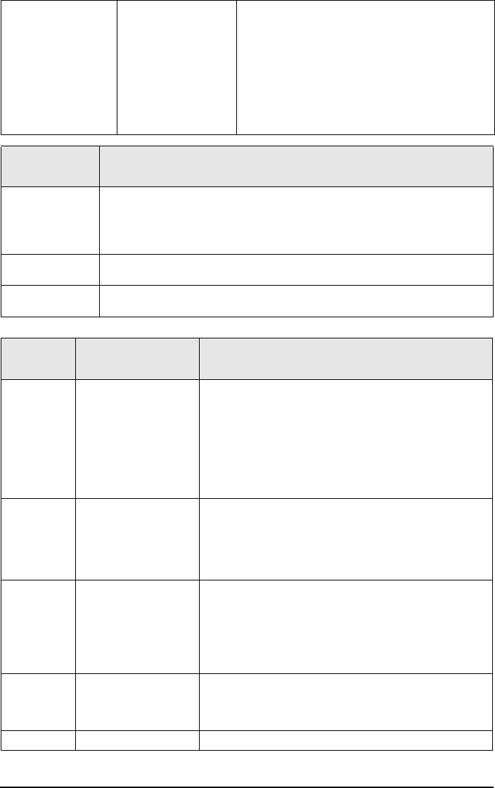
3G4010 Wiring Diagrams
13
Figure 2 - Wiring Diagram
5
41 236789
10 11 14 15 16 17
LE
LI O1 O2 O3 O4
+OC
13
12
AS
L1 L2 L3 L4
1K5
This Connection is necessary
T
I
P
T
I
P
R
I
N
G
R
I
N
G
3G4010
32
DC IN
AUX
231
COM
41
COMT1 R1TIP RING
4
PGM ZONE
+
-
RJ-45
BATTERY
Sealed Rechargeable
12V / 1.2Ah
Typical battery charge: 30-50 mA
Recommended Model: 12V/1.2Ah or
12V/7Ah (for order code 3G4010 only)
Battery not required
if CON5 is ON
9-14VDC/ *700mA (max)
Earth-ground
Ground wire
from building
electrical installation
Inputs to be connected
to dry contact outputs
from alarm control panel
with 5.6KΩ EOL resistors
}
GROUND
CONNECTION
Tighten nut to break paint &
make good connection to
the cabinet.
Nut
Nut
Bolt
Lock washer
Lock washer
Star washer
Cabinet
Alarm Control Panel with
Dialler Interface
(Supports Contact ID format)
Panel Aux Power
or External Power
Supply (13.8VDC
required for normal,
long-term operation)
Telephone Line
Connection
Supervision
Relay
RM1-UL Installations
RM1C-ULC Installations
WARNING: Incorrect connections may result in PTC failure or improper operation. Inspect wiring and ensure connections are correct before turning on.
Connect relay contacts to
a zone input on the alarm
control panel for 3G4010
troubles supervision
(24hr-type zone)
Optional
use of PGM
output (See
Programming)
WARNING!
HIGH VOLTAGE. DISCONNECT AC
POWER & TELEPHONE LINES
PRIOR TO SERVICING
All circuits are classified for UL installations as Power Limited/Class II Power Limited except for the battery leads which are not Power Limited. Do not route any wiring
over circuit boards. Maintain at least 1” (25.4mm) separation. A minimum 1/4” (6.4mm) separation must be maintained at all points between Power Limited wiring
and all other Non-Power Limited wiring. Route wires as indicated in the diagram.
NOTE: For ULC Commercial Fire and Burglary Installation requirements please refer to Figures 5, 6, 7 & 8 and to the ULC Installation Guide P/N 29002157R009.
(Use No. 26 AWG wires for
the connection to PSTN) *Refer to Jumper 3 section
for current rating
For ULC Fire Monitoring installations fire alarm signals shall be sent
simultaneously over POTS line (using the dialler) and over the wireless
network (using 3G4010). Connect alarm output from control panel (PGM)
to the input on the 3G4010 that is programmed as a Fire Alarm Input.
Examples of Control Units/Subscribers Units or Power Supplies compatible
models: DSC PC1864, PC1832, PC1616, PC5204, etc.
3G4010 Wiring Diagrams
14
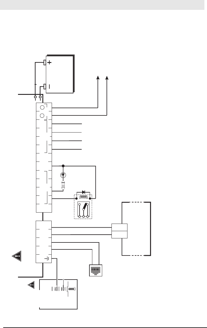
Figure 3 - Telephone Connection
RED (R)
GREEN (T)
GRAY (R)
BROWN (T)
RJ-31X
RING
TIP
CONTROL PANEL
Incoming
Phone line
Handset
RI
TI
T1
R1
TIP
RING
4
321 5
3G4010
TIP T1 R1
RING
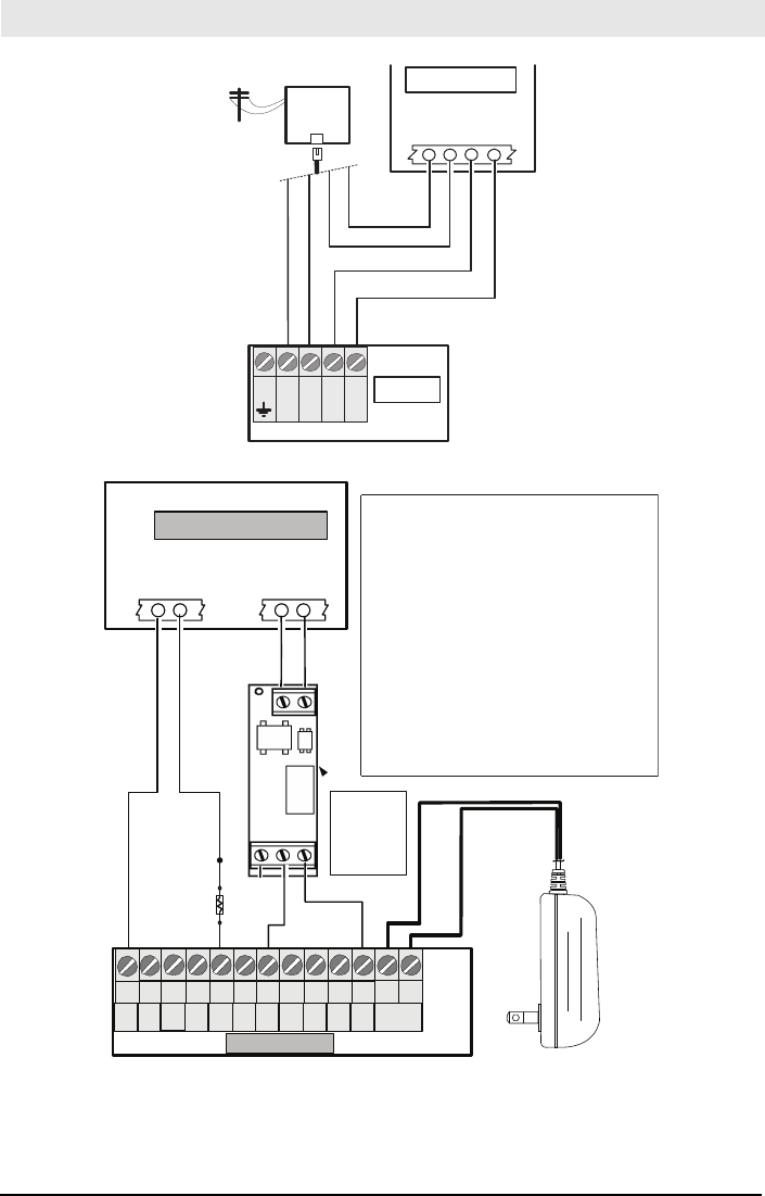
Figure 4 - Power Supply and Supervision Wiring Diagram
(BLK/WHT) +13.8VDC
(BLK ) GND
Control
Panel
EOL
Resistor
See Note 3
DSC
RM-2
RELAY
NC
C
NO
ZONE
TERMINALS
(See Note 1)
- +
+12VDC
GND
CONTROL PANEL
Aux Power
+ -
DSC
Supervision
Relay
See Note 2
17
16
151412 18
13
11
1097 86
19
Z4
Z3Z2
COM 20
Z1
AUX
+
PGM
3
PGM
1
PGM
4
COM
3G4010
PGM
3
DC IN
+ -
DSC ADP1310-NAU
Power Adaptor
NOTES
1. Program the Zone/Point as “Supervisory” type
with keypad only annunciation when in Alarm. Do
NOT use a point that is normally used for
2-Wire Smoke detectors.
2. The power Supervision relay, RM-2 is only used
when the 3G4010 is not powered by the control
panel. When the Radio is powered by the control
panel the relay is not required since a loss of input
power will generate a signal to the CMC.
3. Output 4 on the 3G4010 must be set as “Active
High” (default).
4. When powering the 3G4010 Radio by an
Auxiliary Power supply that has its own backup
battery, insert CON5 jumper on the radio and
remove the 1.2AH battery that came with the radio.
The following wiring diagrams (Figures 5 to 8) are examples of ULC Listed Fire Monitoring Installation
connections.
3G4010 Wiring Diagrams
15
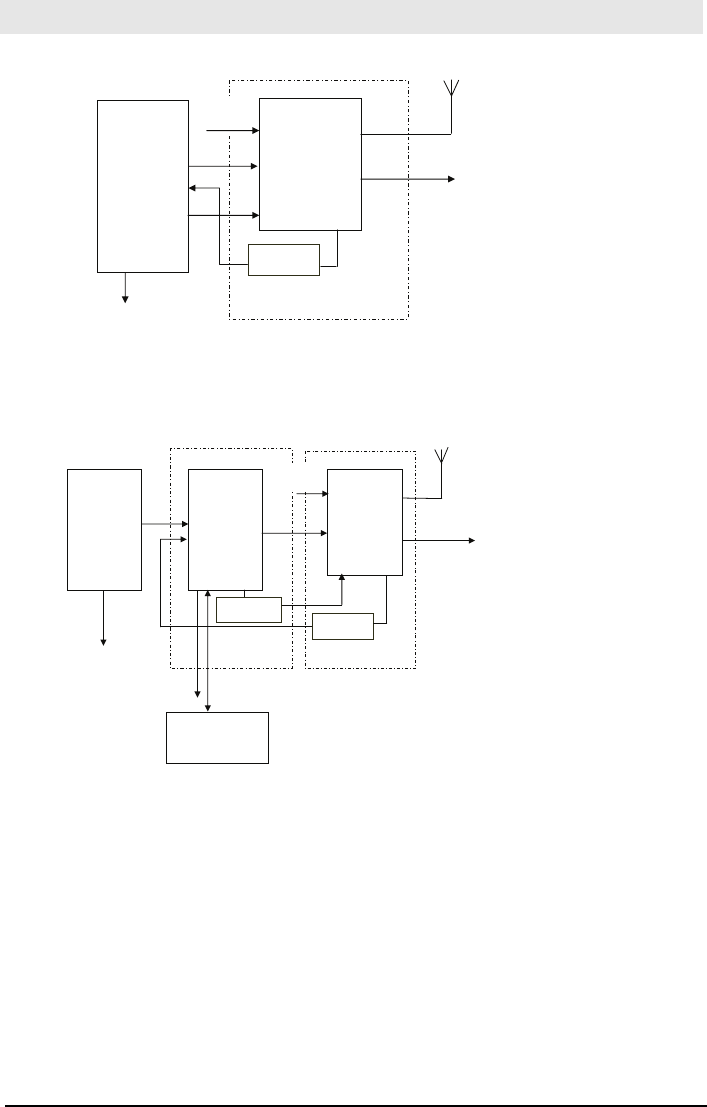
Figure 5 - Fire Alarm Control Unit and 3G Transmitter
Wiring Diagram for Fire Alarm Control Unit (with dialler) and 3G (HSPA/2G (GPRS) Transmitter (Passive Communication System)
AUX Power
(12V/700mA)
RM1C ULC
Relay
Fire Alarm
Control Unit
TIP/RING
Zone Input
Outputs
Fire
Trouble
3G Wireless
Transmitter
3G4010
T1/R1
TIP/RING
Zone PGM4
Inputs Output
3G4010 cabinet
3G (HSPA) or
2G (GPRS)
AC Input
NOTES:
- Power for 3G4010 shall be provided from Fire
Alarm Control Unit or separately Listed power supply
rated for the application, 12V/700mA (Jumper CON5
shall be set to on for Fire Monitoring).
- All wiring connections must be run in a protective
conduit.
- For local supervision of the wireless transmitter connect
PGM output from 3G4010 to one zone input on the
Fire Alarm Control Unit.
- Dry Contact Trouble output from ULC Listed Fire
Alarm Control Unit must be connected to zone input
on the 3G4010 for supervision of Tip/Ring connection.
- Fire Alarms must be sent over both communication
channels. Fire output from Fire Alarm Control Unit
must be connected to the Input 1 on the 3G4010.
- 24h Test Transmission must be enabled on the dialler
and on the 3G4010.
PSTN
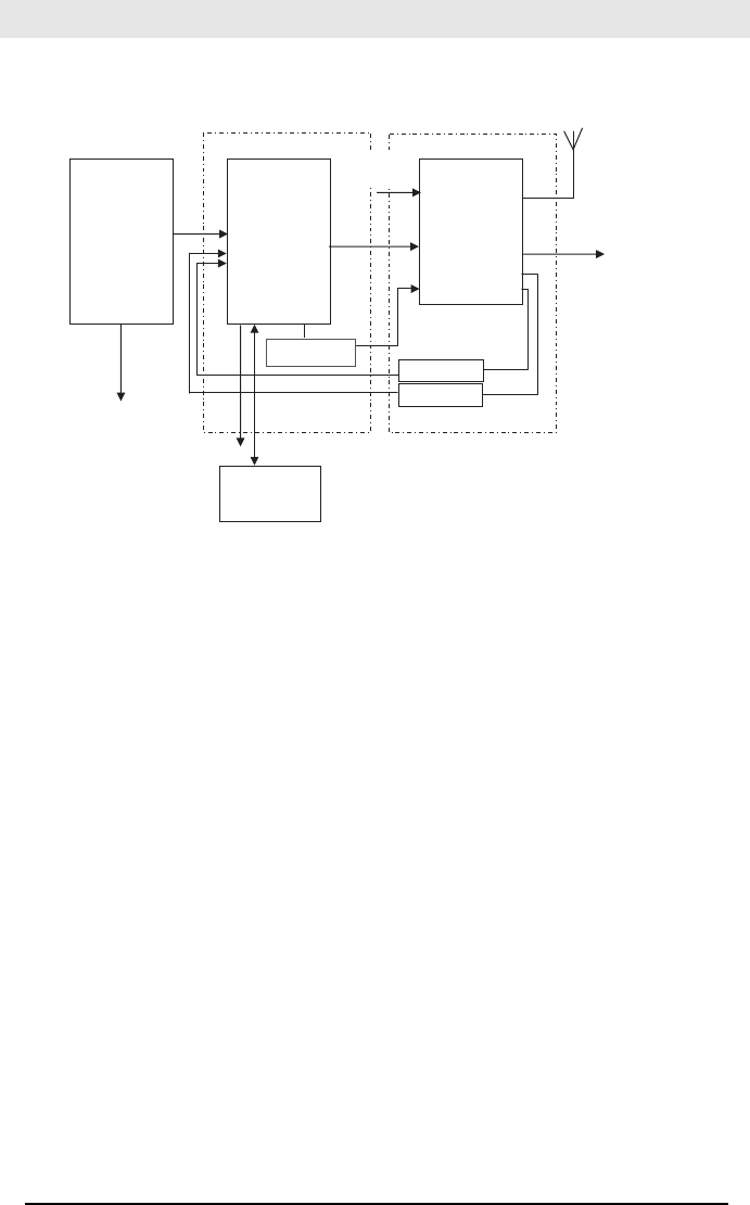
Figure 6 - DSC Subscribers’ Unit Fire and 3G Transmitter Mounted in the Same Room
Wiring Diagram for DSC Subscribers’ Unit Fire and 3G Transmitter
(Passive Communication System)
Fire Alarm
Control Unit
Outputs
Fire
Supervisory
Trouble
DSC
Subscribers’
Unit Fire
Zone
Inputs
TIP
TIP RING
PGM1
DSC Keypad
LCD4501
PK55XX
3G Wireless
Transmitter
3G4010
T1/R1
TIP/RING
Zone
Input PGM4
AUX Power
12V/700mA
RM1C ULC
Relay
PC5003C
PC4050CR
cabine
t
3G (HSPA)/2G (GPRS)
PSTN
AC Input
AC Input
NOTES:
- Power for 3G4010 must be provided from Fire
Alarm Control Unit or separately listed power
supply rated for the application (12V/700mA)
(Jumper CON5 shall be on for Fire Monitoring).
- All wiring connections must be run in a protective conduit.
- Phone Line Monitoring (TLM) must be enabled.
- Connect PGM4 output from 3G4010 (Trouble
Conditions) to a zone input on the Subscriber Unit
for supervision of the GSM Transmitter.
- 24hr Test Transmission over phone line (PSTN) and
3G4010 must be enabled.
- Fire Alarms must be sent over both communication
channels.
- On the Subscribers’ Unit, program PGM1 for
PC1616/PC1832/PC1864 as System Event (Section
[009] as type 10; Section [501] Fire Event option 2
ON). An alternate option is to program PGM1 as Zone
Follower (Sec [009] = 29) and assign Fire Zone to PGM1
in Section [551]. Ensure Bit 3 is on in [501]. In this case,
a restored fire alarm condition does not require the DSC
control panel to be reset.
For PC4020 program PGM1 as type 49 Steady Fire ([00070049]).
- Dry contact outputs from ULC Listed Fire Alarm
Control Unit must be connected to zone inputs on
the ULC Listed DSC Subscribers’ Unit Fire.
PC4020
PC1864
PC1832
PC1616
RM1C ULC
Relay
3G4010 cabinet
- Phone Line trouble is indicated by Yellow LED on 3G4010.
- Refer to detailed diagrams in Figure 7.
3G4010 Wiring Diagrams
16
Figure 7 - DSC Subscribers’ Unit Fire and 3G Wireless Transmitter Mounted Remotely
Alternate Wiring Diagram for DSC Subscribers’ Unit Fire and wireless Transmitter
Passive Communication System -Using Phone Line Supervision Relay
PLEASE NOTE THAT EITHER RM1C ULC OR RM2 RELAYS
CAN BE USED FOR ULC INSTALLATIONS
Fire Alarm
Control Unit
Outputs
Fire
Supervisory
Trouble
DSC
Subscribers’
Unit Fire
Zone
Inputs
TIP
RING
PGM1
DSC Keypad
LCD4501
PK55XX
3G Wireless
Transmitter
3G4010
T1/R1
PGM1
TIP/RING
Zone
Input PGM4
AUX Power
12V/700mA
RM1C ULC
Relay
PC5003C
PC4050CR
cabinet
3G (HSPA)/2G (GPRS)
PSTN
AC Input
AC Input
PC4020
PC1864
PC1832
PC1616
RM1C ULC
Relay
GS30XX cabinet
RM1C ULC
Relay
NOTES:
- Connect PGM output from 3G4010 (Phone Line Trouble)
to a zone input on the subscriber unit for supervision of the
phone line voltage.
- When the 3G4010 is installed remotely from the DSC
Control Panel, it is required to monitor the Phone Line
Trouble condition at the keypad by using an additional
RM1C Relay.
- Refer to detailed diagrams in Figure 8.
3G4010 Wiring Diagrams
17
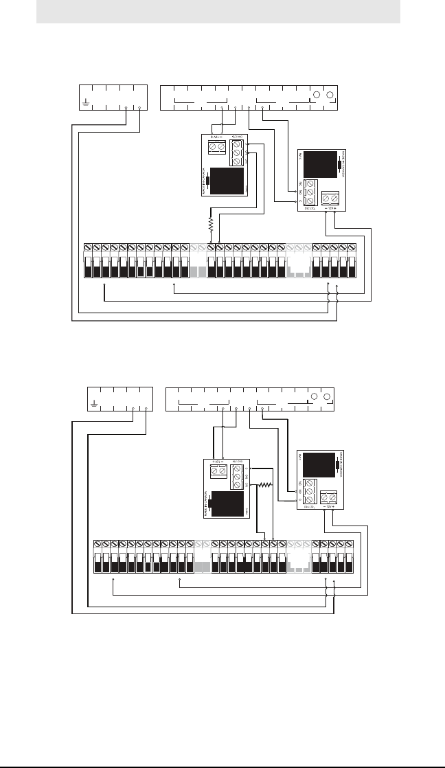
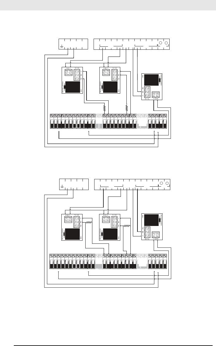
Figure 8 -Connection Details for Wireless Network Supervision Relay and Redundant Fire Alarm Trans-
mission
5.6 KOhm
Wireless Network
Supervision
Relay
Redundant
Fire Alarm
Initiation
5
41 236789
10 11 14 15 16 17 18
LE
LI O1 O2 O3 O4
+OC
13
12
AS
L1 L2 L3 L4
3G4010
AC AC RED BLK YEL GRN Z1 COM Z2 Z3 COM Z4 Z5 COM Z6 Z7 COM Z8
AUX+ BELL+
AUX- BELL-
PGM1 PGM3 EGND TIP T-1
PGM2 PGM4
RING R-1
PC1864
Only
PC1864
PC1832
Only
AC AC RED BLK YEL GRN Z1 COM Z2 Z3 COM Z4 Z5 COM Z6 Z7 COM Z8
AUX+ BELL+
AUX- BELL-
PGM1 PGM3 EGND TIP T-1
PGM2 PGM4
RING R-1
PC1864
Only
PC1864
PC1832
Only
Connection Details for Wireless Network Supervision Relay & Redundant Fire Alarm Transmission
NOTE: Use EOL resistor in series with N.O. contacts of the relay connected to PGM4
32
DC IN
AUX
231
COM
41
COMT1 R1TIP RING
4
PGM ZONE
+
-
5.6 KOhm
Wireless Network
Supervision
Relay
Redundant
Fire Alarm
Initiation
3G4010
AC AC RED BLK YEL GRN Z1 COM Z2 Z3 COM Z4 Z5 COM Z6 Z7 COM Z8
AUX+ BELL+
AUX- BELL-
PGM1 PGM3 EGND TIP T-1
PGM2 PGM4
RING R-1
PC1864
Only
PC1864
PC1832
Only
AC AC RED BLK YEL GRN Z1 COM Z2 Z3 COM Z4 Z5 COM Z6 Z7 COM Z8
AUX+ BELL+
AUX- BELL-
PGM1 PGM3 EGND TIP T-1
PGM2 PGM4
RING R-1
PC1864
Only
PC1864
PC1832
Only
Connection Details for wireless network Supervision Relay & Redundant Fire Alarm Transmission
NOTE: Use EOL resistor in parallel with N.C. contacts of the relay connected to PGM4
32 DC INAUX
231
COM
41
COMT1 R1TIP RING
4
PGM ZONE
+
-
3G4010 Wiring Diagrams
18
Figure 9 - Connection Details for GSM Supervision Relay, Phone Line Supervision and
Redundant Fire Alarm Transmission
32
DC IN
AUX
231
COM
41
COMT1 R1TIP RING
4
PGM ZONE
+
-
5.6 KOhm
5.6 KOhm
Wireless
Network
Supervision
Relay
Phone Line
Supervision
Relay
Redundant
Fire Alarm
Initiation
3G4010
AC AC RED BLK YEL GRN Z1 COM Z2 Z3 COM Z4 Z5 COM Z6 Z7 COM Z8
AUX+ BELL+
AUX- BELL-
PGM1 PGM3 EGND TIP T-1
PGM2 PGM4
RING R-1
PC1864
Only
PC1864
PC1832
Only
AC AC RED BLK YEL GRN Z1 COM Z2 Z3 COM Z4 Z5 COM Z6 Z7 COM Z8
AUX+ BELL+
AUX- BELL-
PGM1 PGM3 EGND TIP T-1
PGM2 PGM4
RING R-1
PC1864
Only
PC1864
PC1832
Only
Connection Details for Wireless Network Supervision Relay, Phone Line Supervision Relay
and Redundant Fire Alarm Transmission
NOTE: Use EOL resistor in series with N.O. contacts of the relay connected to PGM4
5.6
KOhm
5.6
KOhm
Wireless
Network
Supervision
Relay
Phone Line
Supervision
Relay
Redundant
Fire Alarm
Initiation
3G4010
AC AC RED BLK YEL GRN Z1 COM Z2 Z3 COM Z4 Z5 COM Z6 Z7 COM Z8
AUX+ BELL+
AUX- BELL-
PGM1 PGM3 EGND TIP T-1
PGM2 PGM4
RING R-1
PC1864
Only
PC1864
PC1832
Only
AC AC RED BLK YEL GRN Z1 COM Z2 Z3 COM Z4 Z5 COM Z6 Z7 COM Z8
AUX+ BELL+
AUX- BELL-
PGM1 PGM3 EGND TIP T-1
PGM2 PGM4
RING R-1
PC1864
Only
PC1864
PC1832
Only
Connection Details for Wireless Network Supervision Relay, Phone Line Supervision Relay
and Redundant Fire Alarm Transmission
NOTE: Use EOL resistor in parallel with N.C. contacts of the relay connected to PGM4
21
COMT1 R1TIP RING
3DC INAUX
231
COM
44
PGM ZONE
+
-

19
I
MPORTANT READ CAREFULLY: DSC Software purchased with or without Products and Components is copyrighted and is purchased under the
following license terms:
• This End User License Agreement ("EULA") is a legal agreement
between You (the company, individual or entity who acquired the Soft-
ware and any related Hardware) and Digital Security Controls, a divi-
sion of Tyco Safety Products Canada Ltd. ("DSC"), the manufacturer of
the integrated security systems and the developer of the software and
any related products or components ("HARDWARE") which You
acquired.
• If the DSC software product ("SOFTWARE PRODUCT" or "SOFTWARE")
is intended to be accompanied by HARDWARE, and is NOT accom-
panied by new HARDWARE, You may not use, copy or install the
SOFTWARE PRODUCT. The SOFTWARE PRODUCT includes com-
puter software, and may include associated media, printed materials,
and "online" or electronic documentation.
• Any software provided along with the SOFTWARE PRODUCT that is
associated with a separate end user license agreement is licensed to
You under the terms of that license agreement.
• By installing, copying, downloading, storing, accessing or otherwise
using the SOFTWARE PRODUCT, You agree unconditionally to be
bound by the terms of this EULA, even if this EULA is deemed to be a
modification of any previous arrangement or contract. If You do not
agree to the terms of this EULA, DSC is unwilling to license the SOFT-
WARE PRODUCT to You, and You have no right to use it.
SOFTWARE PRODUCT LICENSE
The SOFTWARE PRODUCT is protected by copyright laws and interna-
tional copyright treaties, as well as other intellectual property laws and
treaties. The SOFTWARE PRODUCT is licensed, not sold.
1. GRANT OF LICENSE. This EULA grants You the following rights:
(a) Software Installation and Use - For each license You acquire, You
may have only one copy of the SOFTWARE PRODUCT installed.
(b) Storage/Network Use - The SOFTWARE PRODUCT may not be
installed, accessed, displayed, run, shared or used concurrently on or
from different computers, including a workstation, terminal or other digi-
tal electronic device ("Device"). In other words, if You have several work-
stations, You will have to acquire a license for each workstation where
the SOFTWARE will be used.
(c) Backup Copy - You may make back up copies of the SOFTWARE
PRODUCT, but You may only have one copy per license installed at any
given time. You may use the back up copy solely for archival purposes.
Except as expressly provided in this EULA, You may not otherwise make
copies of the SOFTWARE PRODUCT, including the printed materials
accompanying the SOFTWARE.
2. DESCRIPTION OF OTHER RIGHTS AND LIMITATIONS
(a) Limitations on Reverse Engineering, Decompilation and Disassembly
- You may not reverse engineer, decompile, or disassemble the SOFT-
WARE PRODUCT, except and only to the extent that such activity is
expressly permitted by applicable law notwithstanding this limitation.
You may not make any changes or modifications to the Software, without
the written permission of an officer of DSC. You may not remove any
proprietary notices, marks or labels from the Software Product. You shall
institute reasonable measures to ensure compliance with the terms and
conditions of this EULA.
(b) Separation of Components - The SOFTWARE PRODUCT is licensed
as a single product. Its component parts may not be separated for use
on more than one HARDWARE unit.
(c) Single INTEGRATED PRODUCT - If You acquired this SOFTWARE
with HARDWARE, then the SOFTWARE PRODUCT is licensed with the
HARDWARE as a single integrated product. In this case, the SOFT-
WARE PRODUCT may only be used with the HARDWARE as set forth in
this EULA.
(d) Rental - You may not rent, lease or lend the SOFTWARE PRODUCT.
You may not make it available to others or post it on a server or web site.
(e) Software Product Transfer - You may transfer all of Your rights under
this EULA only as part of a permanent sale or transfer of the HARD-
WARE, provided You retain no copies, You transfer all of the SOFTWARE
PRODUCT (including all component parts, the media and printed mate-
rials, any upgrades and this EULA), and provided the recipient agrees
to the terms of this EULA. If the SOFTWARE PRODUCT is an upgrade,
any transfer must also include all prior versions of the SOFTWARE
PRODUCT.
(f) Termination - Without prejudice to any other rights, DSC may termi-
nate this EULA if You fail to comply with the terms and conditions of this
EULA. In such event, You must destroy all copies of the SOFTWARE
PRODUCT and all of its component parts.
(g) Trademarks - This EULA does not grant You any rights in connection
with any trademarks or service marks of DSC or its suppliers.
3. COPYRIGHT
All title and intellectual property rights in and to the SOFTWARE PROD-
UCT (including but not limited to any images, photographs, and text
incorporated into the SOFTWARE PRODUCT), the accompanying
printed materials, and any copies of the SOFTWARE PRODUCT, are
owned by DSC or its suppliers. You may not copy the printed materials
accompanying the SOFTWARE PRODUCT. All title and intellectual prop-
erty rights in and to the content which may be accessed through use of
the SOFTWARE PRODUCT are the property of the respective content
owner and may be protected by applicable copyright or other intellec-
tual property laws and treaties. This EULA grants You no rights to use
such content. All rights not expressly granted under this EULA are
reserved by DSC and its suppliers.
4. EXPORT RESTRICTIONS
You agree that You will not export or re export the SOFTWARE PROD-
UCT to any country, person, or entity subject to Canadian export restric-
tions.
5. CHOICE OF LAW: This Software License Agreement is governed by
the laws of the Province of Ontario, Canada.
6. ARBITRATION
All disputes arising in connection with this Agreement shall be deter-
mined by final and binding arbitration in accordance with the Arbitration
Act, and the parties agree to be bound by the arbitrator's decision. The
place of arbitration shall be Toronto, Canada, and the language of the
arbitration shall be English.
7. LIMITED WARRANTY
(a) NO WARRANTY
DSC PROVIDES THE SOFTWARE "AS IS" WITHOUT WARRANTY. DSC
DOES NOT WARRANT THAT THE SOFTWARE WILL MEET YOUR
REQUIREMENTS OR THAT OPERATION OF THE SOFTWARE WILL BE
UNINTERRUPTED OR ERROR-FREE.
(b) CHANGES IN OPERATING ENVIRONMENT
DSC shall not be responsible for problems caused by changes in the
operating characteristics of the HARDWARE, or for problems in the inter-
action of the SOFTWARE PRODUCT with non-DSC-SOFTWARE or
HARDWARE PRODUCTS.
(c) LIMITATION OF LIABILITY; WARRANTY REFLECTS ALLOCATION OF
RISK
IN ANY EVENT, IF ANY STATUTE IMPLIES WARRANTIES OR CONDI-
TIONS NOT STATED IN THIS LICENSE AGREEMENT, DSC'S ENTIRE
LIABILITY UNDER ANY PROVISION OF THIS LICENSE AGREEMENT
SHALL BE LIMITED TO THE GREATER OF THE AMOUNT ACTUALLY
PAID BY YOU TO LICENSE THE SOFTWARE PRODUCT AND FIVE
CANADIAN DOLLARS (CAD$5.00). BECAUSE SOME JURISDICTIONS
DO NOT ALLOW THE EXCLUSION OR LIMITATION OF LIABILITY FOR
CONSEQUENTIAL OR INCIDENTAL DAMAGES, THE ABOVE LIMITA-
TION MAY NOT APPLY TO YOU.
(d) DISCLAIMER OF WARRANTIES
THIS WARRANTY CONTAINS THE ENTIRE WARRANTY AND SHALL BE
IN LIEU OF ANY AND ALL OTHER WARRANTIES, WHETHER
EXPRESSED OR IMPLIED (INCLUDING ALL IMPLIED WARRANTIES OF
MERCHANTABILITY OR FITNESS FOR A PARTICULAR PURPOSE) AND
OF ALL OTHER OBLIGATIONS OR LIABILITIES ON THE PART OF DSC.
DSC MAKES NO OTHER WARRANTIES. DSC NEITHER ASSUMES NOR
AUTHORIZES ANY OTHER PERSON PURPORTING TO ACT ON ITS
BEHALF TO MODIFY OR TO CHANGE THIS WARRANTY, NOR TO
ASSUME FOR IT ANY OTHER WARRANTY OR LIABILITY CONCERNING
THIS SOFTWARE PRODUCT.
(e) EXCLUSIVE REMEDY AND LIMITATION OF WARRANTY
UNDER NO CIRCUMSTANCES SHALL DSC BE LIABLE FOR ANY SPE-
CIAL, INCIDENTAL, CONSEQUENTIAL OR INDIRECT DAMAGES
BASED UPON BREACH OF WARRANTY, BREACH OF CONTRACT,
NEGLIGENCE, STRICT LIABILITY, OR ANY OTHER LEGAL THEORY.
SUCH DAMAGES INCLUDE, BUT ARE NOT LIMITED TO, LOSS OF
PROFITS, LOSS OF THE SOFTWARE PRODUCT OR ANY ASSOCIATED
EQUIPMENT, COST OF CAPITAL, COST OF SUBSTITUTE OR REPLACE-
MENT EQUIPMENT, FACILITIES OR SERVICES, DOWN TIME, PUR-
CHASERS TIME, THE CLAIMS OaF THIRD PARTIES, INCLUDING CUS-
TOMERS, AND INJURY TO PROPERTY.
WARNING: DSC recommends that the entire system be completely
tested on a regular basis. However, despite frequent testing, and due to,
but not limited to, criminal tampering or electrical disruption, it is possi-
ble for this SOFTWARE PRODUCT to fail to perform as expected.
MODIFICATION STATEMENT
Digital Security Controls has not approved any changes or modifications to this
device by the user. Any changes or modifications could void the user’s authority
to operate the equipment.
Digital Security Controls n’approuve aucune modification apportée à
l’appareil par l’utilisateur, quelle qu’en soit la nature. Tout changement ou
modification peuvent annuler le droit d’utilisation de l’appareil par
l’utilisateur.
INTERFERENCE STATEMENT This device complies with Part 15 of the
FCC Rules and Industry Canada licence-exempt RSS standard(s). Operation is
subject to the following two conditions: (1) this device may not cause
interference, and (2) this device must accept any interference, including
interference that may cause undesired operation of the device. Le présent
appareil est conforme aux CNR d'Industrie Canada applicables aux appareils
radio exempts de licence. L'exploitation est autorisée aux deux conditions
suivantes : (1) l'appareil ne doit pas produire de brouillage, et (2) l'utilisateur
de l'appareil doit accepter tout brouillage radioélectrique subi, même si le
brouillage est susceptible d'en compromettre le fonctionnement.
WIRELESS NOTICE
This equipment complies with FCC and IC radiation exposure limits set forth
for an uncontrolled environment. The antenna should be installed and operated
with minimum distance of 20 cm between the radiator and your body.
Antenna gain must be below:
This transmitter must not be co-located or operating in conjunction with any
other antenna or transmitter.
Cet appareil est conforme aux limites d'exposition aux rayonnements de la IC
pour un environnement non contrôlé. L'antenne doit être installé de façon à
garder une distance minimale de 20 centimètres entre la source de
rayonnements et votre corps.
Gain de l'antenne doit être ci-dessous:
L'émetteur ne doit pas être colocalisé ni fonctionner conjointement avec à autre
antenne ou autre émetteur.
FCC CLASS B DIGITAL DEVICE NOTICE
This equipment has been tested and found to comply with the limits for a Class
B digital device, pursuant to part 15 of the FCC Rules. These limits are designed
to provide reasonable protection against harmful interference in a residential
installation. This equipment generates uses and can radiate radio frequency
energy and, if not installed and used in accordance with the instructions, may
cause harmful interference to radio communications. However, there is no
guarantee that interference will not occur in a particular installation. If this
equipment does cause harmful interference to radio or television reception,
which can be determined by turning the equipment off and on, the user is
encouraged to try to correct the interference by one or more of the following
measures:
• Reorient or relocate the receiving antenna.
• Increase the separation between the equipment and receiver.
• Connect the equipment into an outlet on a circuit different from that to which
the receiver is connected.
• Consult the dealer or an experienced radio/TV technician for help
CAN ICES-3 (B) / NMB-3 (B)
This Class B digital apparatus complies with Canadian ICES-003.
Cet appareil numérique de classe B est conforme à la norme canadienne ICES-
003.
FCC ID:F53143G4010
3G4010 Product IdentifierUS: F5314MO00B3G4010
REN:0.0B
USOC Jack:RJ-31X
Telephone Connection Requirements
A plug and jack used to connect this equipment to the premises wiring and
telephone network must comply with the applicable FCC Part 68 rules and
requirements adopted by the ACTA. A compliant telephone cord and modular
plug is provided with this product. It is designed to be connected to a compatible
modular jack that is also compliant. See installation instructions for details.
Ringer Equivalence Number (REN)
The REN is used to determine the number of devices that may be connected to
a telephone line. Excessive RENs on a telephone line may result in the devices
not ringing in response to an incoming call.
In most but not all areas, the sum of RENs should not exceed five (5.0). To be
certain of the number of devices that may be connected to a line, as determined
by the total RENs, contact the local Telephone Company. For products
Frequency Band 3G4010
GSM 850 / FDD V 6.21 dBi
PCS 1900 / FDD II 3.76 dBi
Bande de fréquence 3G4010
GSM 850 / FDD V 6.21 dBi
PCS 1900 / FDD II 3.76 dBi
approved after July 23, 2001, the REN for this product is part of the product
identifier that has the format. US: AAAEQ##TXXXX. The digits represented by ##
are the REN without a decimal point (e.g., 03 is a REN of 0.3). For earlier products,
the REN is separately shown on the label.
Incidence of Harm
If this equipment 3G4010 causes harm to the telephone network, the telephone
company will notify you in advance that temporary discontinuance of service may
be required. But if advance notice is not practical, the Telephone Company will
notify the customer as soon as possible. Also, you will be advised of your right to
file a complaint with the FCC if you believe it is necessary.
Changes in Telephone Company Equipment or Facilities
The Telephone Company may make changes in its facilities, equipment, operations
or procedures that could affect the operation of the equipment. If this happens the
Telephone Company will provide advance notice in order for you to make necessary
modifications to maintain uninterrupted service.
Equipment Maintenance Facility
If trouble is experienced with this equipment for repair or warranty information,
please contact the facility indicated below. If the equipment is causing harm to the
telephone network, the Telephone Company may request that you disconnect the
equipment until the problem is solved. This equipment is of a type that is not
intended to be repaired by the end user.
DSC c/o APL Logistics, 757 Douglas Hill Rd., Lithia Springs, GA 30122
Additional Information
Connection to party line service is subject to state tariffs. Contact the state public
utility commission, public service commission or corporation commission for
information.
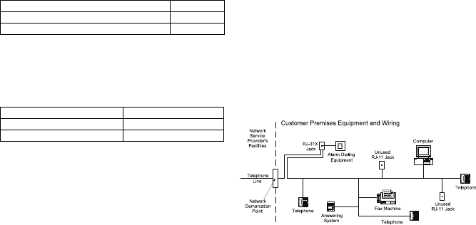
Alarm dialling equipment must be able to seize the telephone line and place a call in
an emergency situation. It must be able to do this even if other equipment (telephone,
answering system, computer modem, etc.) already has the telephone line in use. To
do so, alarm dialling equipment must be connected to a properly installed RJ-31X
jack that is electrically in series with and ahead of all other equipment attached to the
same telephone line. Proper installation is depicted in the figure below. If you have
any questions concerning these instructions, you should consult your telephone
company or a qualified installer about installing the RJ-31X jack and alarm dialling
equipment for
you.
Industry Canada Compliance Statement
This Equipment meets the applicable Industry Canada Terminal Equipment
Technical Specifications. This is confirmed by the registration number. The
abbreviation, IC, before the registration number signifies that registration was
performed based on a Declaration of Conformity indicating that Industry Canada
technical specifications were met. It does not imply that that Industry Canada
approved the equipment. The Ringer Equivalence Number (REN) for this terminal
equipment is 0.0. The REN assigned to each terminal equipment provides an
indication of the maximum number of terminals allowed to be connected to a
telephone interface. The termination on an interface may consist of any combination
of devices subject only to the requirement that the sum of the Ringer Equivalence
Numbers of all devices does not exceed 5.
IC:160A-3G4010
Cet équipement est conforme aux spécifications techniques applicables aux
équipements terminaux d'Industrie Canada. Ceci est confirmé par le numéro
d'enregistrement. L'abréviation IC précédant le numéro d'enregistrement signifie
que l'enregistrement a été effectué sur la base de la Déclaration de conformité
indiquant que le produit est conforme aux spécifications techniques d'Industrie
Canada. Ceci n'implique pas que le produit ait été approuvé par Industrie Canada.
Le nombre équivalent de sonneries (REN) de cet appareil terminal est 0.0. Le REN
attribué à chaque équipement terminal fournit une indication sur le nombre
maximum de terminaux pouvant être connectés sur une interface téléphonique. La
terminaison sur une interface peut constituer en n'importe quelle combinaison
d'appareils, à la condition seulement que la somme des Nombres équivalents de
sonneries de tous les appareils ne soit pas supérieure à 5.
This Class B digital apparatus meets all requirements of the Canadian interference-
causing equipment regulations. Cet appareil numérique de la Classe B respecte
toutes les exigences de règlement sur le matériel brouilleur du Canada.
The term “IC:” before the radio certification number only signifies that Industry
Canada technical specifications were met.
WARNING: To satisfy FCC RF exposure requirements for mobile transmitting devices, a separation distance of 20cm
or more must be maintained between the antenna of this device and persons during device operation.

Tech Support: 1-800-387-3630 (Canada
& US) or 905-760-30000 - www.dsc.com
29009085R001
© 2014 Tyco International Ltd. and its Respective Companies. All Rights Reserved.
The trademarks, logos, and service marks displayed on this document are registered in the United States [or other
countries]. Any misuse of the trademarks is strictly prohibited and Tyco International Ltd. will aggressively enforce its
intellectual property rights to the fullest extent of the law, including pursuit of criminal prosecution wherever necessary. All
trademarks not owned by Tyco International Ltd. are the property of their respective owners, and are used with permission
or allowed under applicable laws.
Product offerings and specifications are subject to change without notice. Actual products may vary from photos. Not all
products include all features. Availability varies by region; contact your sales representative.
Limited Warranty
Digital Security Controls warrants the original purchaser
that for a period of twelve months from the date of
purchase, the product shall be free of defects in materials
and workmanship under normal use. During the warranty
period, Digital Security Controls shall, at its option, repair
or replace any defective product upon return of the prod-
uct to its factory, at no charge for labour and materials.
Any replacement and/or repaired parts are warranted for
the remainder of the original warranty or ninety (90) days,
whichever is longer. The original purchaser must
promptly notify Digital Security Controls in writing that
there is defect in material or workmanship, such written
notice to be received in all events prior to expiration of
the warranty period. There is absolutely no warranty on
software and all software products are sold as a user
license under the terms of the software license agree-
ment included with the product. The Customer assumes
all responsibility for the proper selection, installation,
operation and maintenance of any products purchased
from DSC. Custom products are only warranted to the
extent that they do not function upon delivery. In such
cases, DSC can replace or credit at its option.
International Warranty
The warranty for international customers is the same as
for any customer within Canada and the United States,
with the exception that Digital Security Controls shall not
be responsible for any customs fees, taxes, or VAT that
may be due.
Warranty Procedure
To obtain service under this warranty, please return the
item(s) in question to the point of purchase. All autho-
rized distributors and dealers have a warranty program.
Anyone returning goods to Digital Security Controls must
first obtain an authorization number. Digital Security
Controls will not accept any shipment whatsoever for
which prior authorization has not been obtained.
Conditions to Void Warranty
This warranty applies only to defects in parts and work-
manship relating to normal use. It does not cover:
• damage incurred in shipping or handling;
• damage caused by disaster such as fire, flood, wind,
earthquake or lightning;
• damage due to causes beyond the control of Digital
Security Controls such as excessive voltage, mechanical
shock or water damage;
• damage caused by unauthorized attachment, alter-
ations, modifications or foreign objects;
• damage caused by peripherals (unless such peripherals
were supplied by Digital Security Controls);
• defects caused by failure to provide a suitable installa-
tion environment for the products;
• damage caused by use of the products for purposes
other than those for which it was designed;
• damage from improper maintenance;
• damage arising out of any other abuse, mishandling or
improper application of the products.
Items Not Covered by Warranty
In addition to the items which void the Warranty, the
following items shall not be covered by Warranty: (i)
freight cost to the repair centre; (ii) products which are
not identified with DSC's product label and lot number or
serial number; (iii) products disassembled or repaired in
such a manner as to adversely affect performance or
prevent adequate inspection or testing to verify any war-
ranty claim. Access cards or tags returned for replace-
ment under warranty will be credited or replaced at DSC's
option. Products not covered by this warranty, or other-
wise out of warranty due to age, misuse, or damage shall
be evaluated, and a repair estimate shall be provided. No
repair work will be performed until a valid purchase order
is received from the Customer and a Return Merchandise
Authorisation number (RMA) is issued by DSC's Customer
Service.
Digital Security Controls’ liability for failure to repair the
product under this warranty after a reasonable number of
attempts will be limited to a replacement of the product,
as the exclusive remedy for breach of warranty. Under no
circumstances shall Digital Security Controls be liable for
any special, incidental, or consequential damages based
upon breach of warranty, breach of contract, negligence,
strict liability, or any other legal theory. Such damages
include, but are not limited to, loss of profits, loss of the
product or any associated equipment, cost of capital, cost
of substitute or replacement equipment, facilities or ser-
vices, down time, purchaser’s time, the claims of third
parties, including customers, and injury to property. The
laws of some jurisdictions limit or do not allow the dis-
claimer of consequential damages. If the laws of such a
jurisdiction apply to any claim by or against DSC, the
limitations and disclaimers contained here shall be to the
greatest extent permitted by law. Some states do not
allow the exclusion or limitation of incidental or conse-
quential damages, so that the above may not apply to
you.
Disclaimer of Warranties
This warranty contains the entire warranty and shall be in
lieu of any and all other warranties, whether expressed or
implied (including all implied warranties of merchantabil-
ity or fitness for a particular purpose) and of all other
obligations or liabilities on the part of Digital Security
Controls Digital Security Controls neither assumes
responsibility for nor authorizes any other person pur-
porting to act on its behalf to modify or to change this
warranty, nor to assume for it any other warranty or
liability concerning this product.
This disclaimer of warranties and limited warranty are
governed by the laws of the province of Ontario, Canada.
WARNING: Digital Security Controls recommends that
the entire system be completely tested on a regular
basis. However, despite frequent testing, and due to,
but not limited to, criminal tampering or electrical
disruption, it is possible for this product to fail to
perform as expected.
Out of Warranty Repairs
Digital Security Controls will at its option repair or replace
out-of-warranty products which are returned to its fac-
tory according to the following conditions. Anyone
returning goods to Digital Security Controls must first
obtain an authorization number. Digital Security Controls
will not accept any shipment whatsoever for which prior
authorization has not been obtained.
Products which Digital Security Controls determines to be
repairable will be repaired and returned. A set fee which
Digital Security Controls has predetermined and which
may be revised from time to time, will be charged for
each unit repaired.