Tyco Safety Canada 17LE4000 LTE Cellular Alarm Communicator User Manual My
Digital Security Controls Ltd. LTE Cellular Alarm Communicator My
UserManual.wiki
>
Tyco Safety Canada
>
17LE4000 User Manual
USER INSTALLATION MANUAL
Navigation menu
Upload a User Manual
Namespaces
Wiki Guide
HTML
PDF
Info
Views
User Manual
Discussion / Help
Navigation
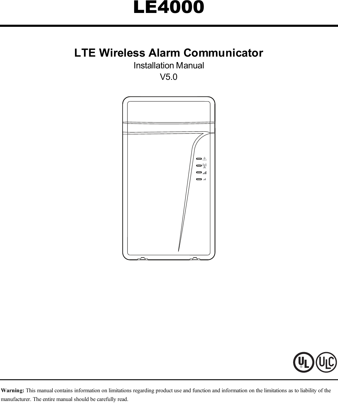
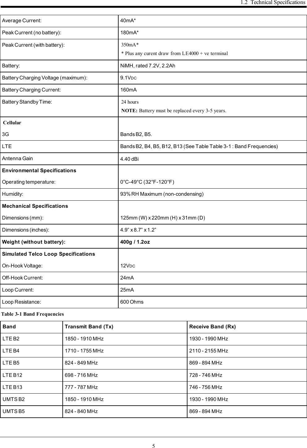
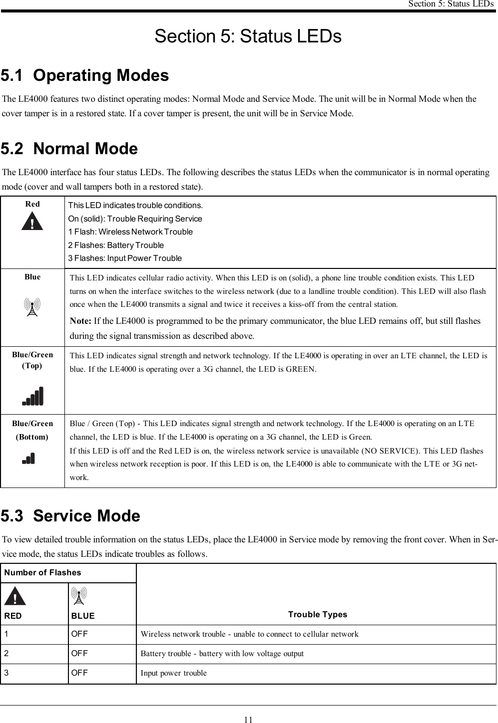
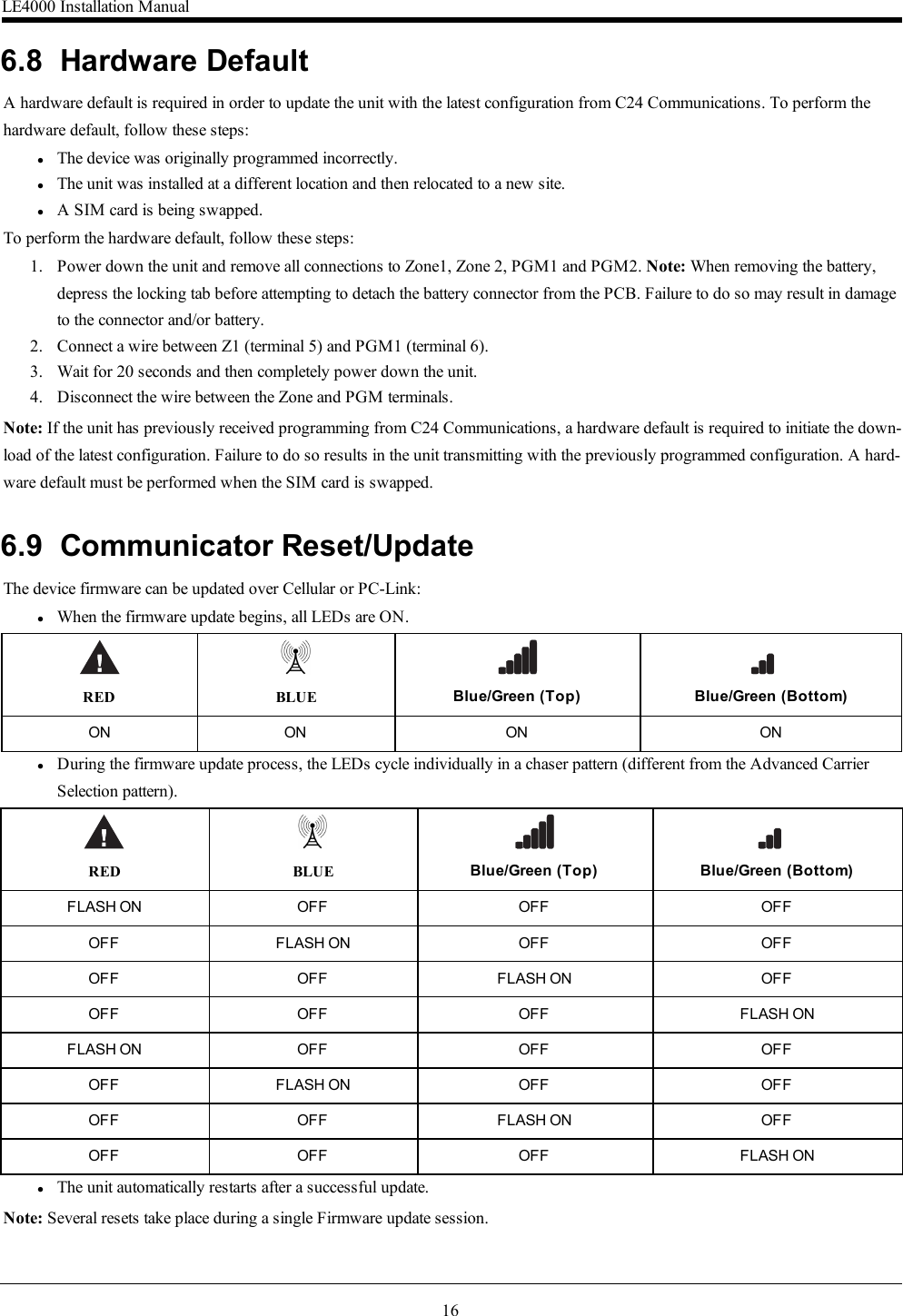
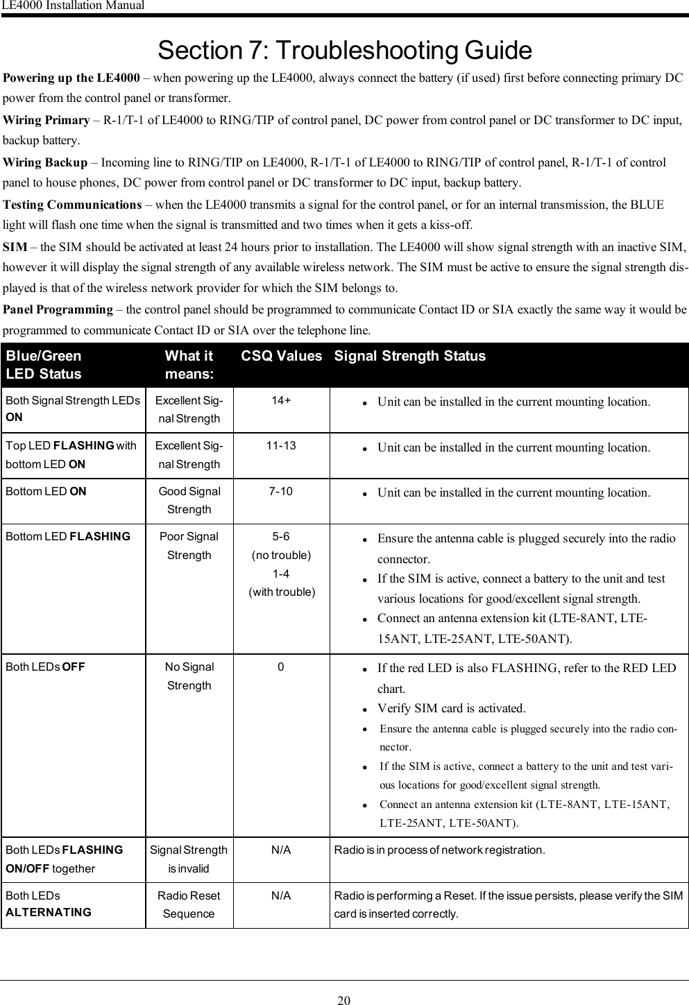
![9Section 3: Installing the LE4000When a signal is reveived back from the central station, The bottom signal strength LED turns on solid.Red Blue Blue/Green (Top) Blue/Green (Bottom)ON ON ON ONIf at least one of the central stations did not respond back to the communicator, the signal strength LED corresponding to that centralstation will turn off. Once the initialization sequence is complete, the LE4000 will move on to steady state operation.Step 6 - Mount the LE4000Note: If using an LE4000 trim plate, snap the LE4000 back plate onto the trim plate before mounting to the wall. If flush mounting orusing with an extension antenna, remove the provided breakaway from the trim plate prior to mounting.1. Using the mounting holes on the LE4000 backplate, mark the four screw locations. Drill the anchor screw holes. NOTE:Check for cable conduits and water pipes before drilling.2. Inspect the mounting surface. Ensure that the surface is flat and will hold the wall tamper closed when mounted. Using anchorscrews (not provided), mount the cabinet to the wall.3. Run the cables through the cable entry [13] or through the cabinet cable run knockout [15].4. Complete the connections on the terminal blocks [12].5. Reattach the front cover [1] securely to the cabinet.Note: Refer to the wiring diagram at the end of this manual.](https://usermanual.wiki/Tyco-Safety-Canada/17LE4000/User-Guide-3679821-Page-9.png)
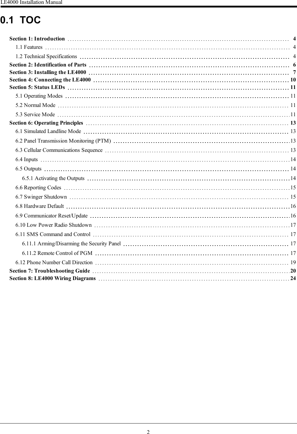
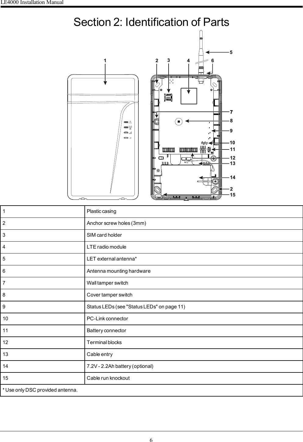
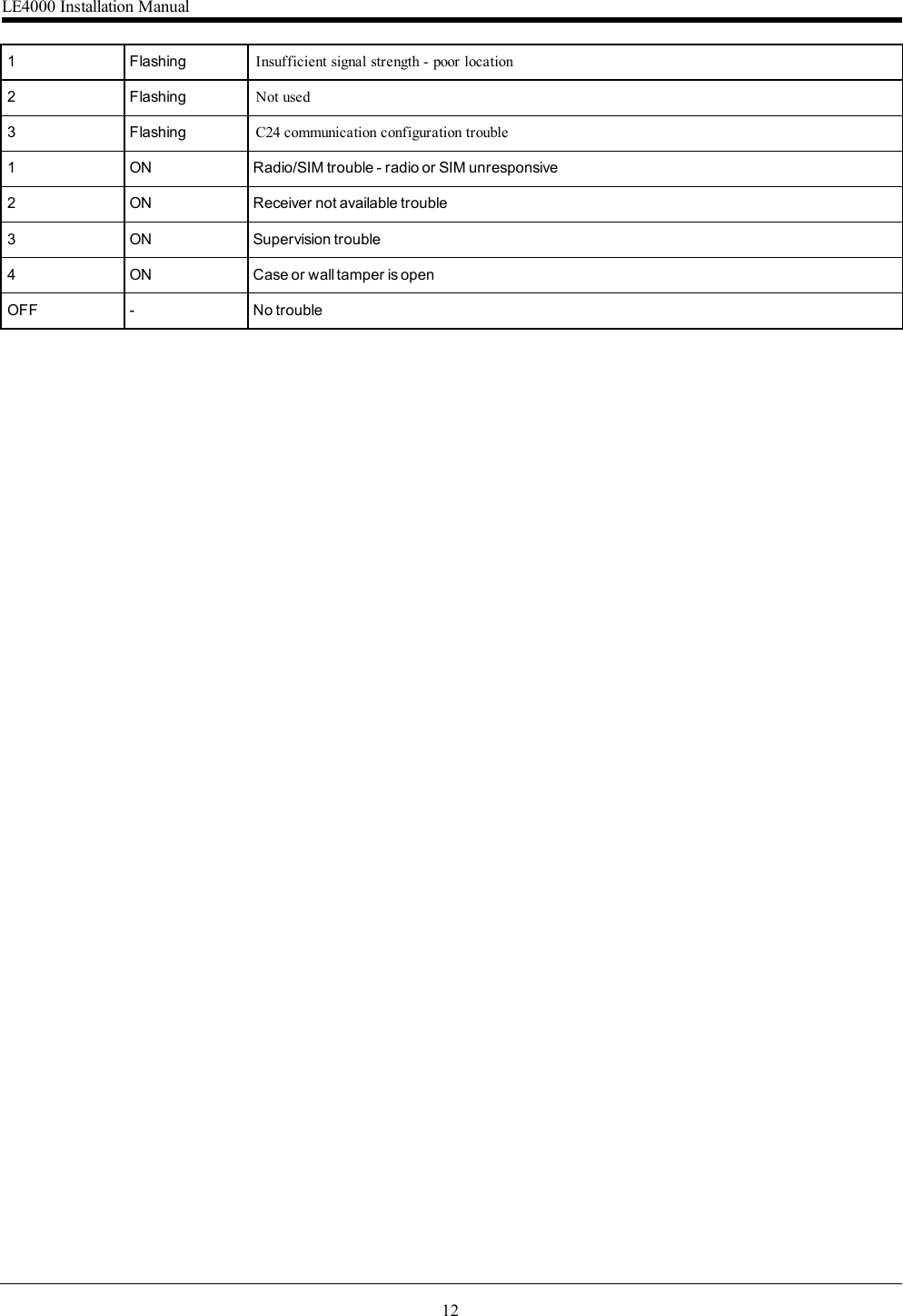
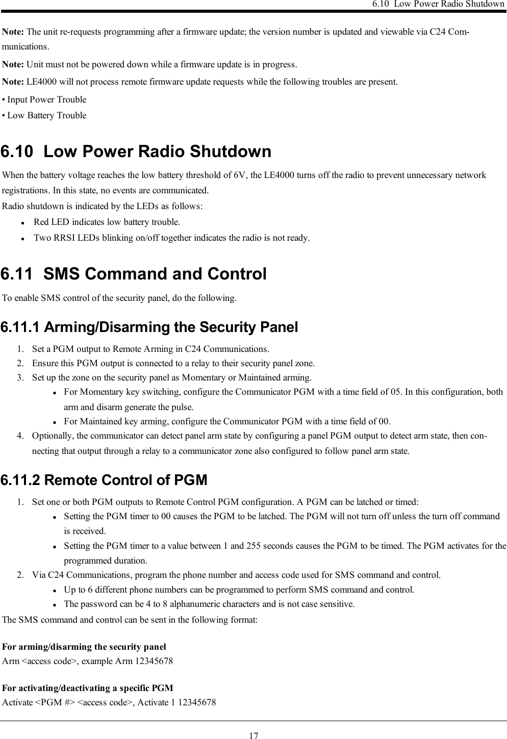
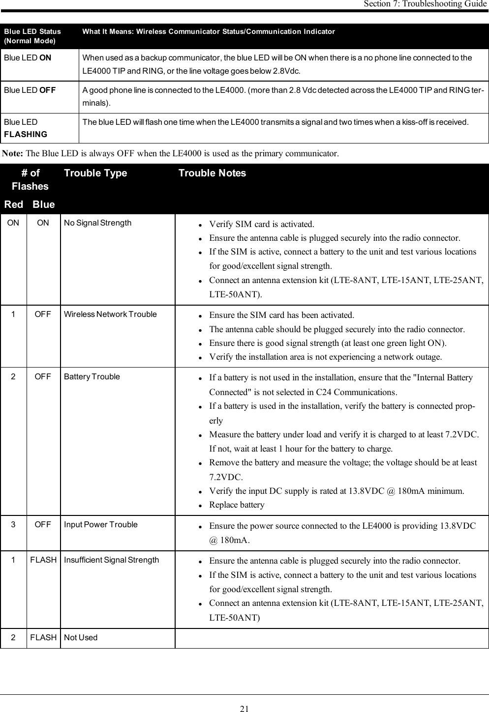
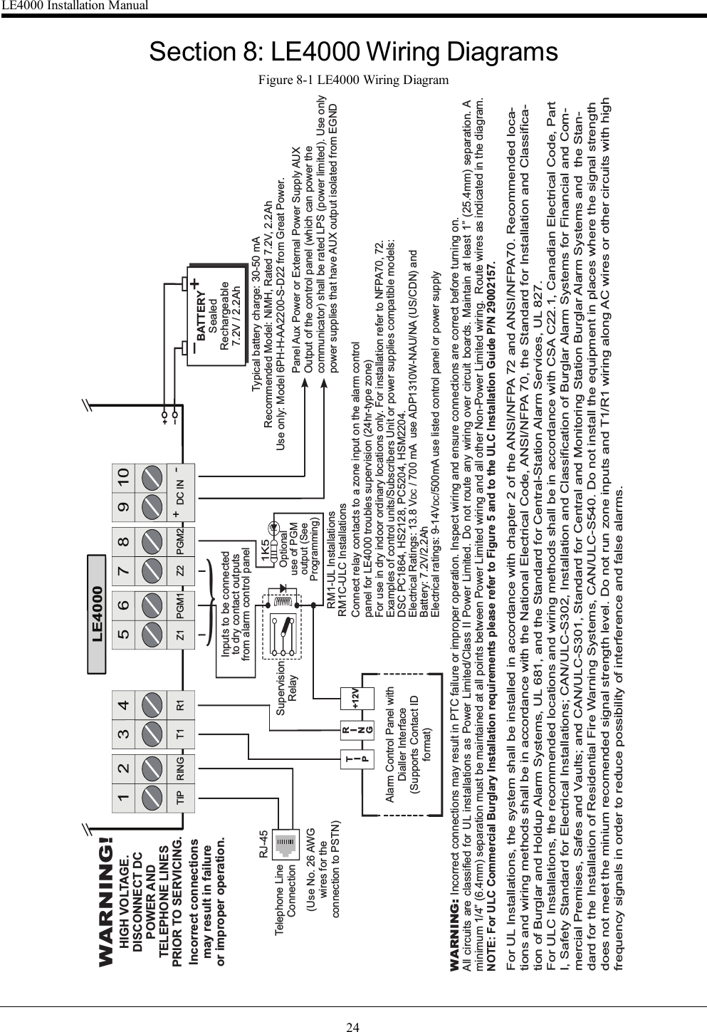
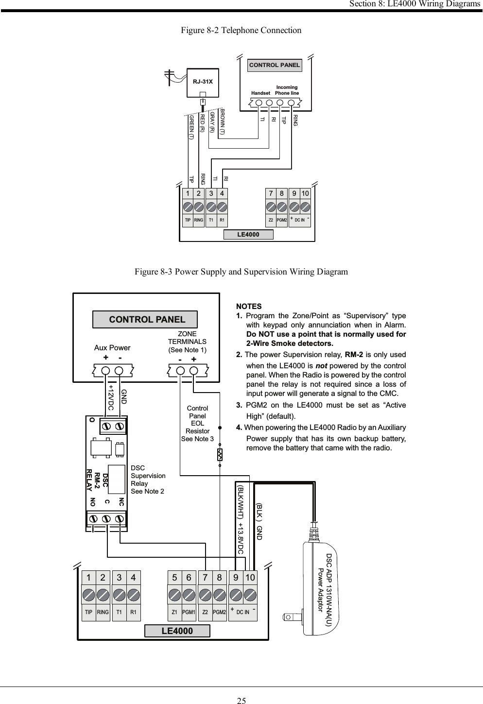
![10Section 4: Connecting the LE4000TIP (1) / RNG (2) External Telephone Line - If the LE4000 is being used as a back-up communicator, these terminals must be con-nected directly to the incoming telephone line.T1 (3) / R1 (4) Internal Telephone Line - These terminals must be connected to the TIP and RING of the control panel.Zone 1 (5) and Zone 2 (7) Programmable Inputs - These terminals can be set up to trigger events. Refer to `Inputs' for details.PGM1 (6), PGM2 (8) Programmable Open-collector Outputs - These outputs can be activated by programmed events. Refer to‘Activating the Outputs’ for details. The maximum current sink of each output must not exceed 50mA.DC in + (9), DC in - (10) Device Power Supply - These terminals must be connected to a rated power supply. Once the connectionsare completed, connect the battery, [11] in Parts diagram) to a 7.2V, 2.2Ah battery.Battery - Loosen the screw on the movable retaining clip and rotate counterclockwise until it is pointing at the bottom of the unit. Ifremoving an existing battery unclip the battery connector from the PCB and lift battery out.CAUTION: Ensure when removing the battery to depress the locking tab before attempting to remove the battery con-nector from the PCB. Failure to do so may result in damage to the connector and/or battery.Insert new battery label side up and connect to PCB. Rotate the movable retaining clip clockwise until horizontal with the bottom ofthe unit and tighten the screw with screwdriver.When disposing of batteries, follow the instructions and precautions printed on the batteries, and contact your municipal offices forinformation on the disposal of used batteries.LE4000 Installation Manual](https://usermanual.wiki/Tyco-Safety-Canada/17LE4000/User-Guide-3679821-Page-10.png)
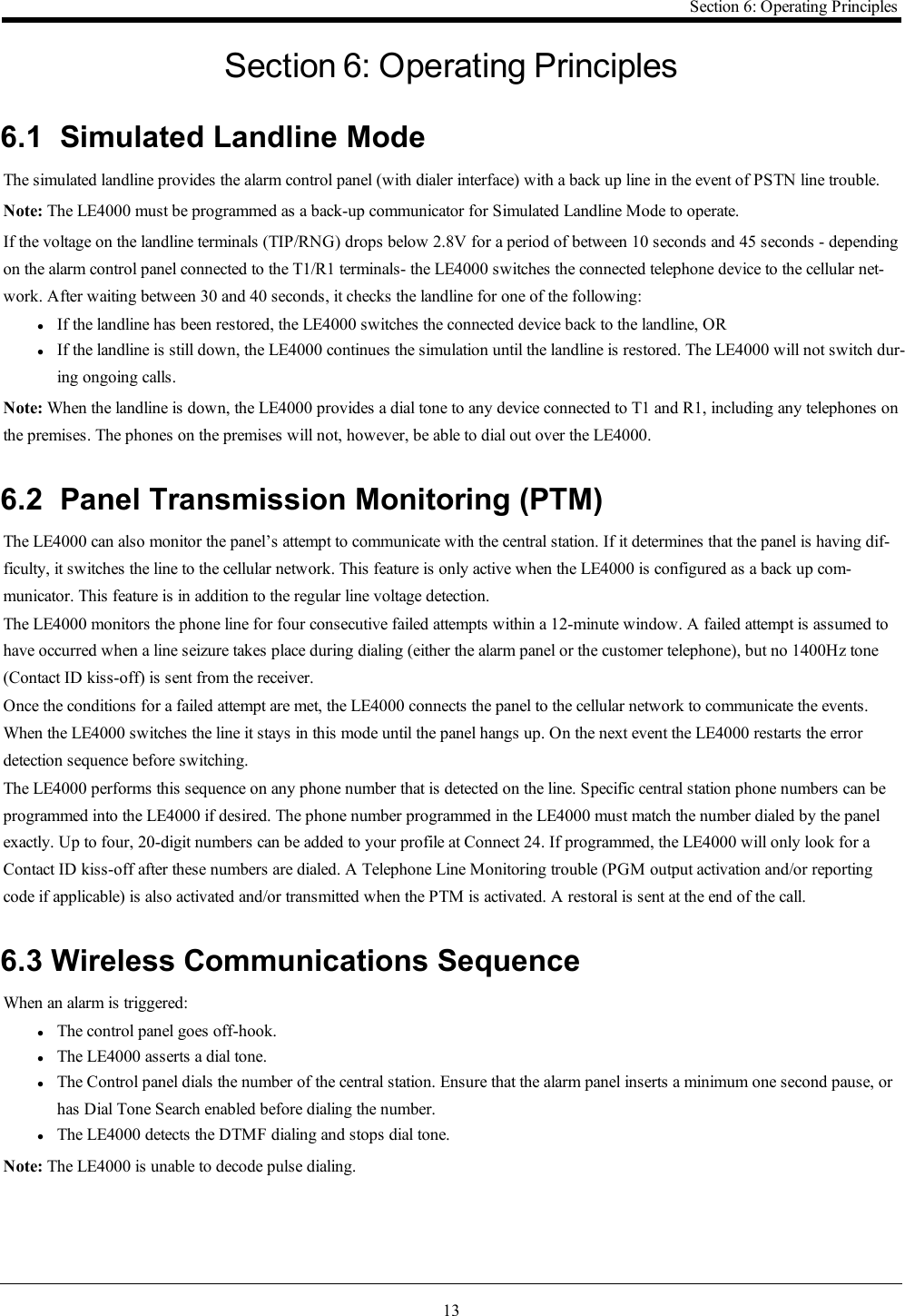
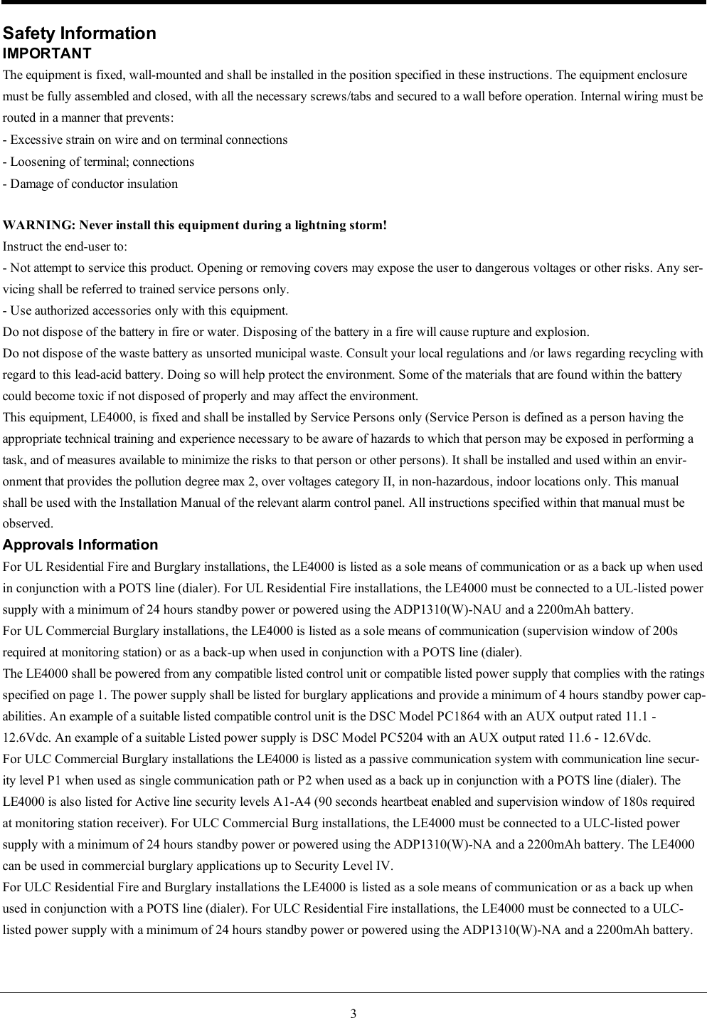
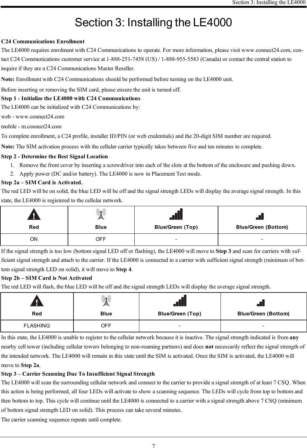
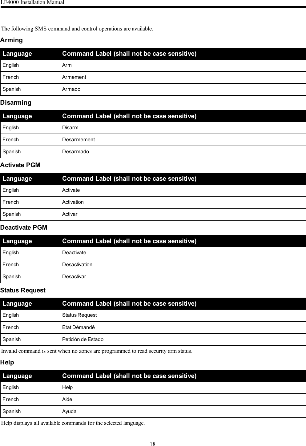
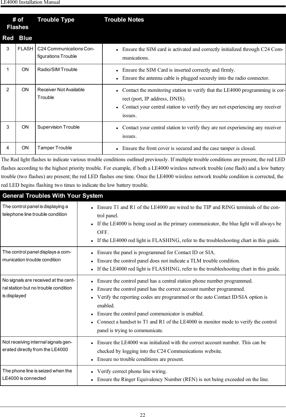
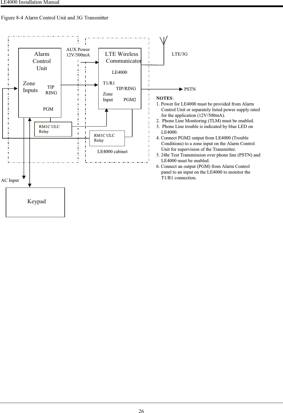
![14If the panel is programmed for Contact ID format:lThe LE4000 sends the required Contact ID dual-tone handshake to the panel.lAfter receiving the handshake, the control panel transmits an alarm message in Contact ID format.lThe LE4000 decodes and transforms the Contact ID digits into an IP packet and sends it to the central station receiver over thecellular network.lThe central station receiver acknowledges the alarm and sends a command to the LE4000 to generate the corresponding1400Hz Kiss-off signal for a minimum of 800 miliseconds.After the LE4000 generates a Kiss-off signal, it sends the next alarm or, if no further alarms need to be sent, the control panel goeson-hook.6.4 InputsThe LE4000 has two inputs that can be used to trigger specific communications. These events will transmit using the Contact ID orSIA format with Inputs 1-4 reporting as [991] to [994] respectively.Default settings are:INPUT 1- BURGLARY ZONEINPUT 2 - SUPERVISORY ALARMThese inputs are normally open and activate when a short condition is detected between teh terminal and the COM. Refer to the wiringdiagram at the back of this manual.6.5 OutputsThe LE4000 has four programmable outputs to activate in response to the associated events. Refer to the LE4000 Wiring Diagram atthe back of this manual for more information.6.5.1 Activating the OutputsThe LE4000 has two open collector outputs capable of a maximum of 50mA. Internal events on the LE4000 can trigger the outputs toturn on an LED or activate an input on the host panel. The default settings are as follows.OUTPUT 1 Wireless Module or Network Trouble - Output is normally high and will switch to ground when the LE4000 can notcommunicate with the LTE or 3Gnetwork.OUTPUT 2 General Module Trouble - Output is normally low and will switch to high when a Wireless Network trouble, PowerSupply/Battery trouble, and/or a Failure to Communicate (FTC) trouble is detected.Note: PGM2 must be connected to the control panel as shown in "LE4000 Wiring Diagrams" on page 24. Program the control panelinput Zone/Point as 24hr ‘Supervisory’ with keypad-only notification when activated. Output 2 on the LE4000 must be set as ‘ActiveHigh’.Note: Once an output has been activated automatically, it will not restore its state until all the causes of activation are cleared.LE4000 Installation Manual](https://usermanual.wiki/Tyco-Safety-Canada/17LE4000/User-Guide-3679821-Page-14.png)
![WarrantyDigital Security Controls warrants the original purchaser that for a period of twelve months from the date ofpurchase, the product shall be free of defects in materials and workmanship under normal use. During the war-ranty period, Digital Security Controls shall, at its option, repair or replace any defective product upon returnof the product to its factory, at no charge for labour and materials. Any replacement and/or repaired parts arewarranted for the remainder of the original warranty or ninety (90) days, whichever is longer. The originalpurchaser must promptly notify Digital Security Controls in writing that there is defect in material or work-manship, such written notice to be received in all events prior to expiration of the warranty period. There isabsolutely no warranty on software and all software products are sold as a user license under the terms of thesoftware license agreement included with the product. The Customer assumes all responsibility for the properselection, installation, operation and maintenance of any products purchased from DSC. Custom products areonly warranted to the extent that they do not function upon delivery. In such cases, DSC can replace or creditat its option.International WarrantyThe warranty for international customers is the same as for any customer within Canada and the United States,with the exception that Digital Security Controls shall not be responsible for any customs fees, taxes, or VATthat may be due.Warranty ProcedureTo obtain service under this warranty, please return the item(s) in question to the point of purchase. All author-ized distributors and dealers have a warranty program. Anyone returning goods to Digital Security Controlsmust first obtain an authorization number. Digital Security Controls will not accept any shipment whatsoeverfor which prior authorization has not been obtained.Conditions to Void WarrantyThis warranty applies only to defects in parts and workmanship relating to normal use. It does not cover:ldamage incurred in shipping or handling;ldamage caused by disaster such as fire, flood, wind, earthquake or lightning;ldamage due to causes beyond the control of Digital Security Controls such as excessive voltage,mechanical shock or water damage;ldamage caused by unauthorized attachment, alterations, modifications or foreign objects;ldamage caused by peripherals (unless such peripherals were supplied by Digital Security Controls);ldefects caused by failure to provide a suitable installation environment for the products;ldamage caused by use of the products for purposes other than those for which it was designed;ldamage from improper maintenance;ldamage arising out of any other abuse, mishandling or improper application of the products.Items Not Covered by WarrantyIn addition to the items which void the Warranty, the following items shall not be covered by Warranty: (i)freight cost to the repair centre; (ii) products which are not identified with DSC's product label and lot numberor serial number; (iii) products disassembled or repaired in such a manner as to adversely affect performanceor prevent adequate inspection or testing to verify any warranty claim. Access cards or tags returned forreplacement under warranty will be credited or replaced at DSC's option. Products not covered by this war-ranty, or otherwise out of warranty due to age, misuse, or damage shall be evaluated, and a repair estimateshall be provided. No repair work will be performed until a valid purchase order is received from the Cus-tomer and a Return Merchandise Authorisation number (RMA) is issued by DSC's Customer Service.Digital Security Controls’s liability for failure to repair the product under this warranty after a reasonable num-ber of attempts will be limited to a replacement of the product, as the exclusive remedy for breach of war-ranty. Under no circumstances shall Digital Security Controls be liable for any special, incidental, orconsequential damages based upon breach of warranty, breach of contract, negligence, strict liability, or anyother legal theory. Such damages include, but are not limited to, loss of profits, loss of the product or any asso-ciated equipment, cost of capital, cost of substitute or replacement equipment, facilities or services, down time,purchaser’s time, the claims of third parties, including customers, and injury to property. The laws of some jur-isdictions limit or do not allow the disclaimer of consequential damages. If the laws of such a jurisdiction applyto any claim by or against DSC, the limitations and disclaimers contained here shall be to the greatest extentpermitted by law. Some states do not allow the exclusion or limitation of incidental or consequential damages,so that the above may not apply to you.Disclaimer of WarrantiesThis warranty contains the entire warranty and shall be in lieu of any and all other warranties, whetherexpressed or implied (including all implied warranties of merchantability or fitness for a particular pur-pose) And of all other obligations or liabilities on the part of Digital Security Controls Digital SecurityControls neither assumes responsibility for, nor authorizes any other person purporting to act on itsbehalf to modify or to change this warranty, nor to assume for it any other warranty or liability con-cerning this product.This disclaimer of warranties and limited warranty are governed by the laws of the province of Ontario,Canada.Digital Security Controls recommends that the entire system be completely tested on a regular basis. However,despite frequent testing, and due to, but not limited to, criminal tampering or electrical disruption, it is possiblefor this product to fail to perform as expected.Installer’s LockoutAny products returned to DSC which have the Installer’s Lockout option enabled and exhibit no other prob-lems will be subject to a service charge.Out of Warranty RepairsDigital Security Controls will at its option repair or replace out-of-warranty products which are returned to itsfactory according to the following conditions. Anyone returning goods to Digital Security Controls must firstobtain an authorization number. Digital Security Controls will not accept any shipment whatsoever for whichprior authorization has not been obtained.Products which Digital Security Controls determines to be repairable will be repaired and returned. A set feewhich Digital Security Controls has predetermined and which may be revised from time to time, will becharged for each unit repaired.Products which Digital Security Controls determines not to be repairable will be replaced by the nearest equi-valent product available at that time. The current market price of the replacement product will be charged foreach replacement unit.© 2017 Tyco Security Products. All Rights Reserved.Tech Support: 1-800-387-3630 (Canada & U.S.) or 905-760-3000www.dsc.comThe trademarks, logos, and service marks displayed on this document are registered in the United States [orother countries]. Any misuse of the trademarks is strictly prohibited and Tyco will aggressively enforce itsintellectual property rights to the fullest extent of the law, including pursuit of criminal prosecution wherevernecessary. All trademarks not owned by Tyco are the property of their respective owners, and are used withpermission or allowed under applicable laws.Product offerings and specifications are subject to change without notice. Actual products may vary from pho-tos. Not all products include all features. Availability varies by region; contact your sales representative.](https://usermanual.wiki/Tyco-Safety-Canada/17LE4000/User-Guide-3679821-Page-29.png)