Tyco Safety Canada 17TL280LER Cellular Alarm Communicator User Manual My
Digital Security Controls Ltd. Cellular Alarm Communicator My
UserManual.wiki
>
Tyco Safety Canada
>
17TL280LER User Manual
Users Manual
Navigation menu
Upload a User Manual
Namespaces
Wiki Guide
HTML
PDF
Info
Views
User Manual
Discussion / Help
Navigation
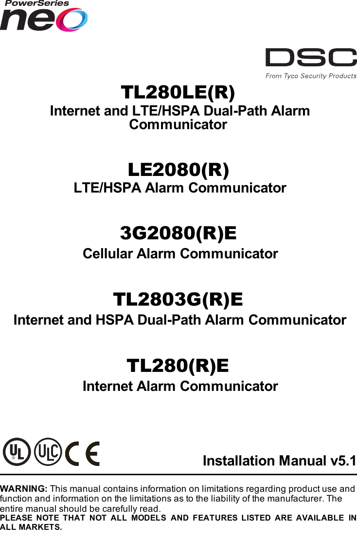
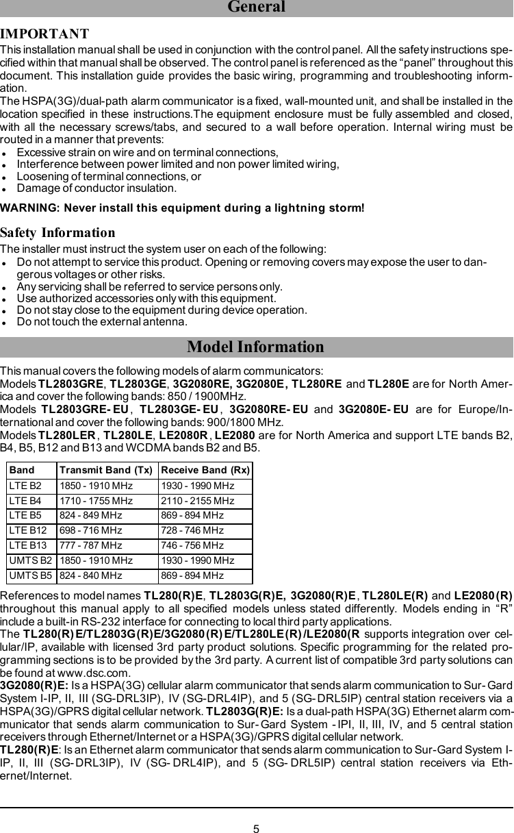
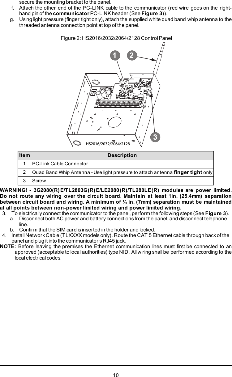
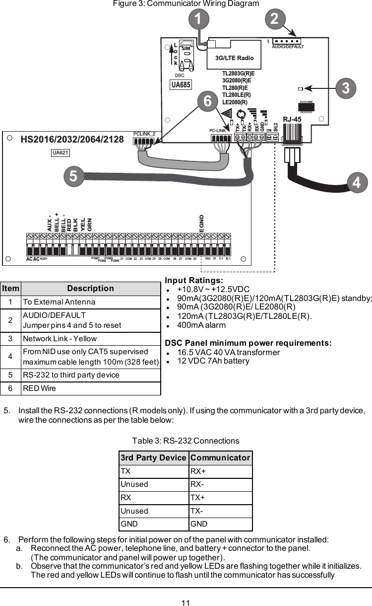
![Ratings CompatibilityTable 1: Communicator RatingsModel3G2080(R)E /LE2080(R)Cellular onlyTL280(R)EInternet onlyTL2803G(R)E/TL280LE(R)Internet and CellularPower Supply RatingsInput Voltage10.8-12.5 VDCPower is supplied from the panel’s PC-Link header or PCL-422 module in remotecabinet installations. In remote cabinet installations, the PCL-422 module locatedwith the communicator is powered by an HSM2204 or an HSM2300. Refer to thePCL-422 installation sheet for details.Current ConsumptionStandby Current 90mA @ 13.66V 120mA @ 13.66VAlarm (Transmitting)Current 400mA @ 12VOperatingFrequency 850MHz, 1900MHzTypical AntennaGain 2dBiEnvironmental SpecificationsOperatingTemperature -10°C to 55°CHumidity 5% ~ 93% relative humidity, non-condensingMechanical SpecificationsBoard Dimensions(mm) 100 × 150 × 15 100 × 150 × 15Weight (grams) withbracket 310 320Table 2: Compatible Receivers and PanelsCommunicator Receiver/Panel Description3G2080(R)ELE2080(R)TL2803G(R)ETL280LE(R)TL280(R)EReceiverlSur-Gard System I-IP Receiver, version 1.13+lSur-Gard System II Receiver, version 2.10+lSur-Gard SG-DRL3-IP, version 2.30+ (for Sur-Gard System IIIReceiver)lSur-Gard SG-DRL4-IP version 1.20+ (for Sur-Gard System IVReceiver)lSur-Gard SG-DRL5-IP version 1.00+ (for Sur-Gard System 5Receiver)PanellHS2016lHS2016-4lHS2032lHS2064lHS2128NOTE: Enter [*][8][Installer Code][900] at keypad to view the panel version number.Pre Installation ConfigurationEncryptionThe communicator uses 128 Bit AES encryption. Encryption can only be enabled from the monitoring sta-tion receiver. Each receiver (Ethernet 1 and 2, cellular 1 and 2) can independently have encryption7](https://usermanual.wiki/Tyco-Safety-Canada/17TL280LER/User-Guide-3446153-Page-7.png)
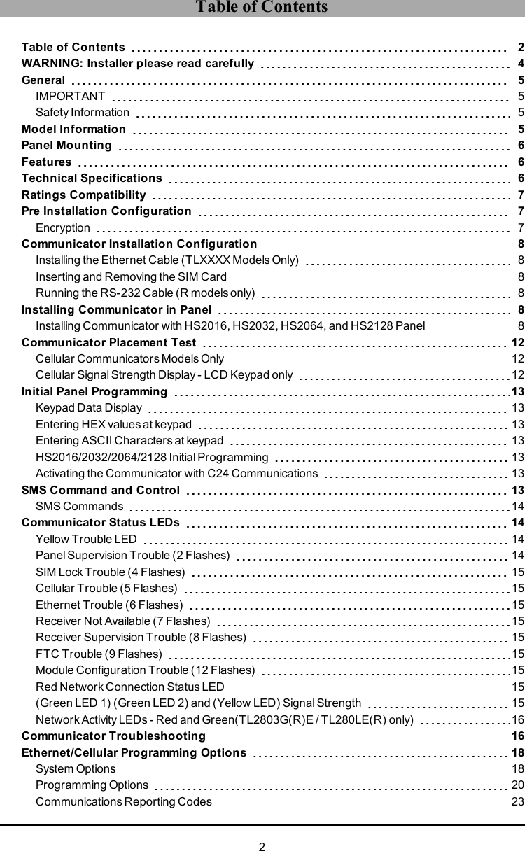
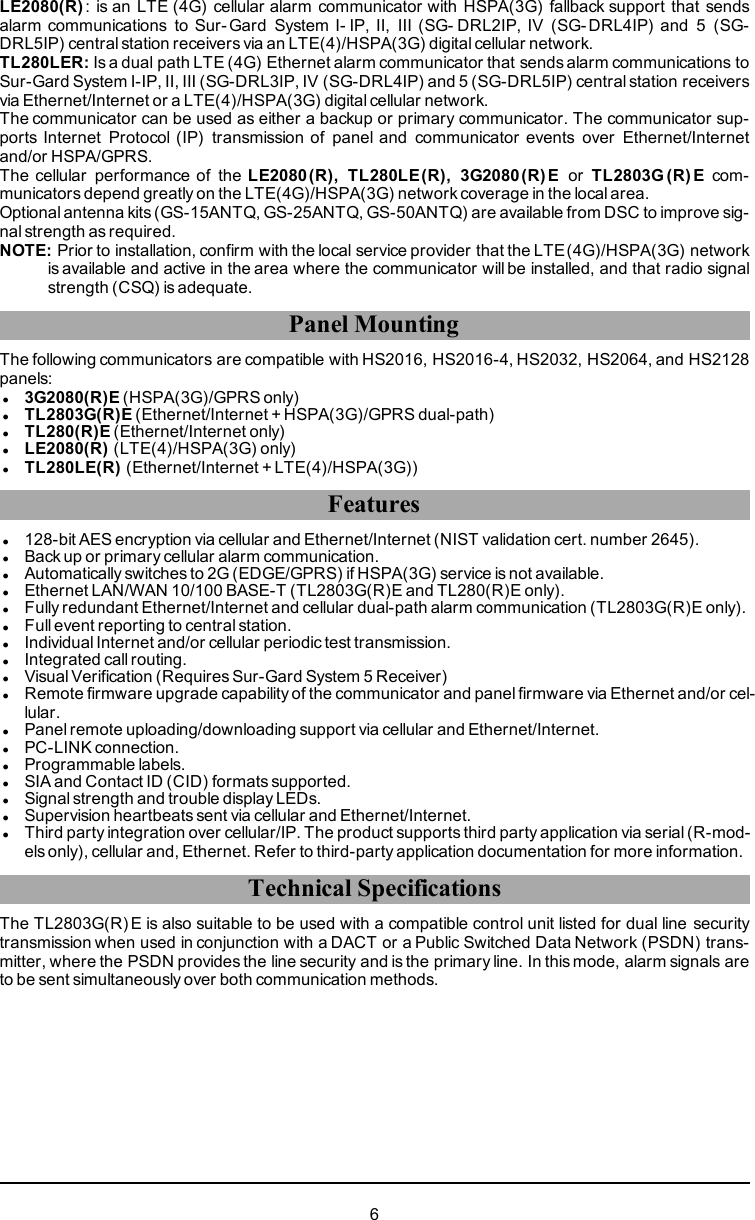
![communicated to all programmed receivers. If this is the first time the communicator has beenpowered up in the panel, the module willinitiate communications to C24 Communications torequest remote programming.NOTE: During radio reset, the two green LEDs will flash alternately.NOTE: Initialization may take several minutes to complete. Red and yellow LEDs will flash together dur-ing initialization. Do not continue to next step until the red and yellow LEDs have stopped flashing.(If only the yellow LED is flashing, there is a communicator trouble and the green LEDs are notvalid for communicator placement test). Correct trouble indicated by flashes on yellow LED beforecontinuing. (See Table 8 for troubleshooting assistance).7. Perform the communicator placement test below.8. Mount the panel in final location indicated by placement test.Communicator Placement TestCellular Communicators Models OnlyTo confirm that the cellular antenna location is suitable for radio operation, perform the placement test asfollows:NOTE: It might be necessary to relocate the panel or install an optional extension antenna during this pro-cedure, if the radio signal strength is too low.1. Confirm that the yellow LED on the communicator is not flashing. A flashing yellow LED indicatestrouble on the communicator. See Table 8 to troubleshoot and correct the cause of this troublebefore continuing to the next step.2. Confirm that the strength of the radio signal on the yellow LED and the 2 green LEDs on the com-municator meet or exceed the minimum signal level requirement. Minimum signal level: The yellowLED is OFF and the green LED 1(furthest from the yellow LED) is ON (i.e., not flashing) for the panel location to be acceptable. Forinterpretation of receiver strength on LEDs, refer to the table “Radio Signal Strength” on page10.Cellular Signal Strength Display - LCD Keypad onlyThe cellular network signal strength can be checked on the keypad LCD screen by entering installer pro-gramming section [850]. The LCD will indicate the SIM card activation status followed by up to five bars ofsignal strength. This display will automatically update every three seconds. For the relationship betweensignal strength bars, CSQ level, and signal level in dBm, refer to “Radio Signal Strength” on page10.Table 4: Signal Strength DisplayDescription DisplaySIM card active and current signal strengthSIM card inactive and current signal strengthRadio not registeredOR ANDNOTE: If the required signal strength is too low with the panel in its current location, the panel must berelocated or an external antenna is required.If required, the following cellular extension antenna kits are available to the installer:lGS-15ANTQ - 4.57m (15’) internal antenna extension kit (suitable for interior mounting).lGS-25ANTQ - 7.62m (25’) external antenna extension kit (suitable for interior/exterior mounting).lGS-50ANTQ - 15.24m(50’) external antenna extension kit (suitable for interior/exterior mounting).Specific instructions for the installation of the extension antenna are included with the kit. Observe all theelectrical safety instructions regarding the installation of the antenna. All the wiring of the equipment shallbe fully compliant with the local rules and regulations.3. If required, install the antenna extension and perform the following steps to determine the best loc-ation for placement of the antenna:a. Disconnect the white whip antenna from the panel.b. Attach one end of the antenna extension cable to the threaded antenna connector on the paneland the other end to the external antenna.12](https://usermanual.wiki/Tyco-Safety-Canada/17TL280LER/User-Guide-3446153-Page-12.png)
![4. Move the extension antenna to various locations while observing the two green LEDs on the panel.a. Continue to reposition the extension antenna until it receives an acceptable (minimum onegreen LED ON solid) signal strength.NOTE: Minimum strength is: green LED 1 flashing and yellow LED off. If green LED 1 isflashing, relocation should be considered.b. Mount the supplied antenna extension bracket at the location that provides the best signalstrength.5. Alternately, reposition the panel to improve signal strength. Dismount the panel and move it toanother location to achieve the required signal strength. If the panel is relocated to improve signalstrength, mount it in the new location.6. When final panel/antenna location is determined, continue at the Initial Panel Programming sec-tion.NOTE: If the SIM card is not activated, placement test will indicate the signal strength of the nearest cel-lular tower.NOTE: In between displaying signal strength, the signal strength LEDs will flash alternately if an inactiveSIM card is used. The flashing indicates that the module is attempting to attach to the cellular net-work and will only last briefly.Initial Panel ProgrammingKeypad Data DisplaylSection-Toggle Options: The number is displayed when toggle is ON and the number is not dis-played when toggle is OFF. (e.g., toggle options displays: [--3--6--]. Options 3 and 6 are ON, all oth-ers are OFF). Pressing keys 1 through 8 will alternately turn the toggle ON and OFF.lHEX/Decimal Data: Values that are provided with two defaults, separated by a “/” character, use theformat: hexadecimal followed by decimal equivalent (e.g., default [0BF5/3061]). Hexadecimal num-bers are shown, with all leading zeroes, to the full field length defined for the number.Entering HEX values at keypadTo enter HEX values at the keypad, press the * key before entering the HEX value. (e.g., to enter “C” atthe keypad, press [*][3])Entering ASCII Characters at keypad1. Press [*] and use scroll buttons [<] [>] to display “ASCII Entry” on the LCD screen.2. Press [*] to select ASCII entry mode.3. Use the [<] [>] scroll keys to display the desired character and press [*] to save and exit ASCII.4. Repeat the steps above to enter another ASCII character.HS2016/2032/2064/2128 Initial ProgrammingFor detailed information, refer to panel manual section ‘Alternate Communicator Set-up’. These sectionsmust be programmed at the panel keypad. Enter [*][8] [Installer Code] [Section Number]. Recordany values that are modified from their default, in the appropriate worksheets for the panel or com-municator.1. In panel section [377] ‘Communication Variables’, subsection [002] ‘Communication Delays’, sub-subsection [1] ‘Communication Delay’, program 060 (seconds).2. In panel section [382] ‘Communicator Option 3’ set option [5] ONNOTE: If this option is OFF, the yellow status LED on the communicator will indicate ‘Panel SupervisionTrouble’ (2 flashes) and the unit can not be programmed via the PC-LINK cable.Activating the Communicator with C24 CommunicationsInstallation of the 3G2080(R)E / LE2080(R) or TL2803G(R)E / TL280LE(R) requires activation with C24Communications in order to operate. Please contact the central station (C24 Communications MasterReseller) to confirm the required steps to activate/program the communicator.NOTE: NOTE: The SIM activation with the carrier can take several hours to complete. It is recom-mended the activation be completed prior to arrival on the customer site to avoid possible install-ation delays.Once the SIM activation is complete, the communicator will automatically connect and download its pro-gramming from C24 Communications.SMS Command and ControlCertain functions can be performed on the alarm panel by remote, using SMS text messages. In addi-tion, the system sends SMS messages to confirm commands. SMS programming options are accessed13](https://usermanual.wiki/Tyco-Safety-Canada/17TL280LER/User-Guide-3446153-Page-13.png)
![through programming section [851].The security system only responds to SMS messages sent from designated phone numbers (pro-grammed in section [851]>[311]-[328]).SMS CommandslStay arm the systemlAway arm the systemlNight arm the systemlDisarm the systemlActivate command output 1lActivate command output 2lActivate command output 3lActivate command output 4lDeactivate command output 1lDeactivate command output 2lDeactivate command output 3lDeactivate command output 4lSystem status requestlAlarm memory requestlZone bypasslZone unbypassSMS text messages must be formatted as follows:<function name><space><partition #><space><access code>(e.g., Stay Arm partition 1 1234). Once the command is received and executed by the alarm system, aconfirmation text message is received.NOTE: For more information about SMS commands and control functions, refer to the Neo 1.1 UserManual.Communicator Status LEDsThe communicator has four on-board LED indicators. These include one yellow trouble LED, one rednetwork connection status LED and two green signal strength LEDs. The LED meaning is described inthis section.Yellow Trouble LEDThis yellow LED will flash to indicate a trouble on the unit. The number of flashes indicates the type oftrouble. See the table below for the coded flashes and the conditions which willactivate the trouble statusLED.Table 5: Yellow Trouble Status LED# ofFlashes Trouble # ofFlashes Trouble2 Panel Supervision Trouble 8 Receiver Supervision Trouble4 Not Applicable 9 FTC Trouble5 Cellular Trouble 10 C24 Communications Configuration Failure6 Ethernet Trouble 12 Module Configuration Trouble7 Receiver Not Available TroubleNOTE: Only the highest priority trouble (2 flashes is the highest priority trouble) is indicated. When thistrouble is restored, the next highest trouble will indicate, if present. This will continue until alltroubles have been cleared (yellow LED is not flashing).The following paragraphs describe the conditions associated with the trouble indicated:Panel Supervision Trouble (2 Flashes)This trouble will be indicated when communication between the communicator module and the panelfails. If the module can not communicate with the panel (e.g., loss of power to the panel) the com-municator will send the ‘Panel Absent Trouble Event’ message to the central station receiver. When com-munication returns, a ‘Panel Absent Restore Event’ is sent by the communicator to the central stationreceiver. The reporting codes are ET0001 for trouble and ER0001 for restore. The panel absent eventalways uses the primary receiver account code when communicating to the central station.14](https://usermanual.wiki/Tyco-Safety-Canada/17TL280LER/User-Guide-3446153-Page-14.png)
![NOTE: The panel supervision trouble/restore are internally generated events by the communicator.Trouble is generated if the communicator misses 6 polls. Trouble is restored on receipt of first pollfrom the panel.SIM Lock Trouble (4 Flashes)This trouble occurs when the SIM lock feature has been enabled and the unit has been programmedwith the wrong PIN for the SIM card.Cellular Trouble (5 Flashes)This trouble is indicated for any of the following 4 conditions:1. Radio Failure: Trouble is indicated after 8 failed attempts to communicate with the cellular radio.2. SIM Failure: Trouble is indicated after 10 failed attempts to communicate with the SIM.3. Cellular Network Trouble: Trouble is indicated for loss of the registration to the network provider.4. Insufficient Signal Strength: Trouble is indicated if calculated average signal strength is too low.(Both green LEDs are OFF). Trouble will clear when the calculated average signal strength isabove minimum (i.e., > CSQ 5).NOTE: If Option [851][005] Bit 8 is Off, CSQ less than or equal to 4 will not trigger Cellular TroubleEthernet Trouble (6 Flashes)This trouble is indicated when an Ethernet link between the transmitter and the local switch or router isabsent. This trouble will also be indicated if the unit fails to get Dynamic Host Control Protocol (DHCP) set-tings from the DHCP server. (Not active if Ethernet receivers are not programmed).Receiver Not Available (7 Flashes)This trouble is indicated if the unit is not able to successfully initialize with any of the programmed receiv-ers. Unprogrammed receivers are excluded. This trouble is also indicated if the cellular receiver APNshave not been programmed in sections [205] and [215].Receiver Supervision Trouble (8 Flashes)This trouble is indicated when receiver supervision is enabled and communication between the com-municator module and the receiver fails. Trouble is indicated if Ethernet 1 and/or cellular 1 is supervisedand does not receive a heartbeat from the receiver or if cellular is supervised and the unit does notreceive an acknowledgment to 4 heartbeats sent to the receiver.FTC Trouble (9 Flashes)This trouble is indicated when the unit fails to communicate module events to the central station. Troubleis displayed after the unit has exhausted all communications attempts to all programmed receivers forevents generated by the communicator.Module Configuration Trouble (12 Flashes)This trouble is indicated when the system account code or the receiver account have not been pro-grammed. Disabled receivers are excluded.Red Network Connection Status LEDTL280(R)E / TL280LE(R) / TL2803G(R)E onlyBLINKING: Indicates communications in progress.lOnce quickly for outgoing Ethernet transmission.lTwice quickly to indicate incoming Ethernet ACK/NACK.OFF: This is the normal state of the red network connection status LED. There are no network con-nection issues present.ON: There is a problem with the Ethernet or the cellular network connection. LED will be ON if any of thefollowing occur: Ethernet cable is not connected, DHCP configuration times out, unit fails to get an IPaddress from the cellular network, or Cellular connection has been reset.(Green LED 1) (Green LED 2) and (Yellow LED) Signal StrengthNOTE: If the yellow LED is flashing, signal strength in table below is not valid.See Table 8 for troubleshooting flashing yellow LED.15](https://usermanual.wiki/Tyco-Safety-Canada/17TL280LER/User-Guide-3446153-Page-15.png)
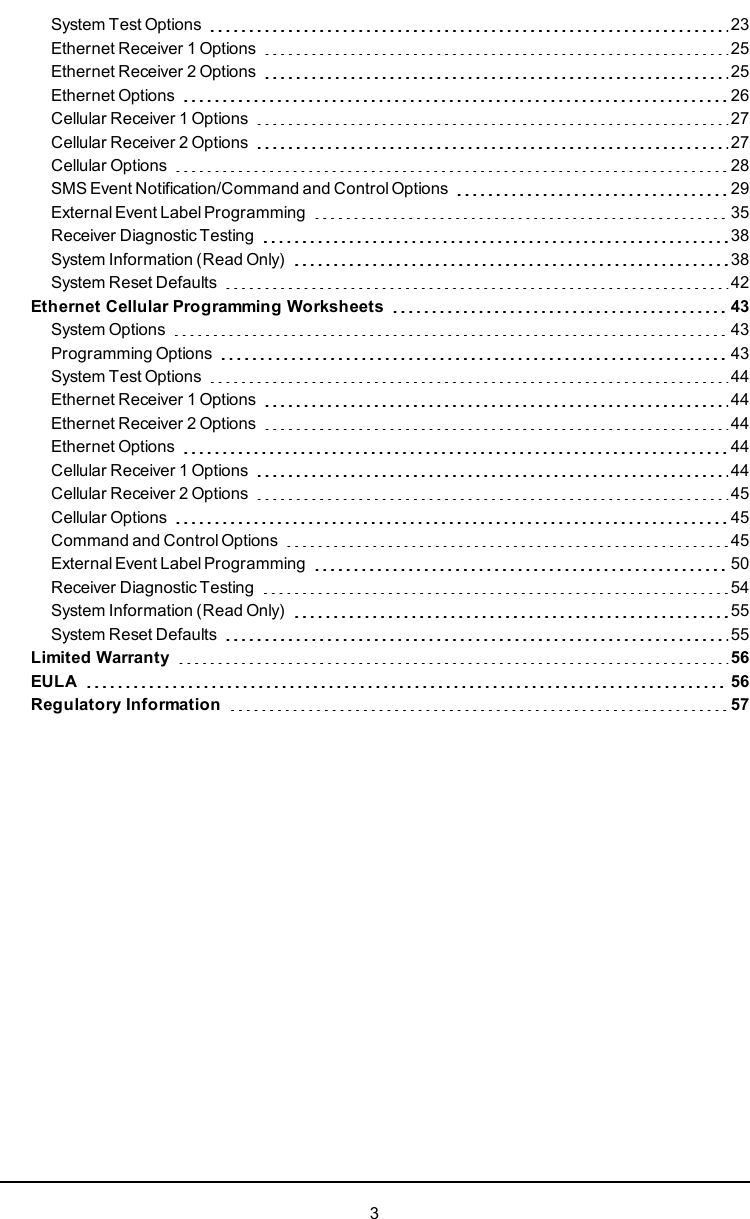
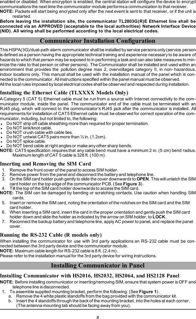
![Table 6: Radio Signal StrengthSignalStrengthCSQLevelYellowLEDGreenLED 2GreenLED 1SignalLeveldBmAction RequiredRadio NotReady N/A N/A AlternateFlashingAlternateFlashing N/AIf this status persists and the yellowLED shows 5 flashes, confirm that theSIM card is active.Confirm cellular service is active inarea.Relocate panel or install externalantenna.No Signal 0 ON OFF OFF -108.8 Check all antenna connections.1 Bar 1 - 4FlashingSeeNoteOFF Flashing -108 ~ -103 Relocate panel or install externalantenna if yellow trouble LED showsfive flashes.2 Bars 5 - 6 OFF OFF Flashing -102 ~ -993 Bars 7 - 10 OFF OFF ON -98 ~ -91Location is OK. Cellular signal strengthis greater than CSQ 7.4 Bars 11-13 OFF Flashing ON -90 ~ -855 Bars 14 + OFF ON ON -84 andhigherNOTE: The communicator will indicate cellular trouble (yellow LED = 5 flashes) if the calculated averageCSQ Level is 4 or less. The communicator signal strength can be viewed remotely with C24 Com-munications.Network Activity LEDs - Red and Green(TL2803G(R)E / TL280LE(R) only)lEthernet Activity: Red LED will blink quickly once for transmit, or twice for receive.lCellular Activity: Green LED 2 will blink quickly once for transmit, or twice for receiveCommunicator TroubleshootingNOTE: For additional details:lRefer to section [983] for troubleshooting the firmware updateslRefer to section [984] to view the trouble statuslRefer to section [985] for troubleshooting radio initializationTable 7: Trouble IndicationsTroubleindicationTroubleIndicatorDigitPossibleCauses Trouble Possible SolutionNoIndication N/A No PowerlCheck the power connections between the panel andthe communicator.lConfirm PC-LINK cable is properly installed betweencommunicator and panel.Yellow LED– ON Solid N/A No SignallConfirm that cellular network service is active in thearea.lEnsure the antenna is securely connected to the radio.Check antenna stub cable is securely connected to theradio.lIf an external antenna is used, ensure the antenna issecurely screwed on to the antenna cable connector.Check external antenna for damage or open/short.Trouble 02 Panel lCheck section [382] toggle option[5] is ON (Alternate16](https://usermanual.wiki/Tyco-Safety-Canada/17TL280LER/User-Guide-3446153-Page-16.png)
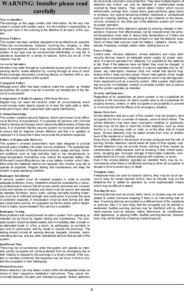
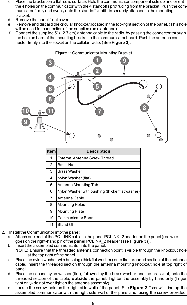
![TroubleindicationTroubleIndicatorDigitPossibleCauses Trouble Possible SolutionLED – 2FlashesSupervisionTroubleCommunicator Enabled).lEnsure the PC-LINK cable between the panel andcommunicator is connected properly (not reversed) andis securely in place.Yellow LED– 5 Flashes 05 CellularTroublelConfirm that cellular service is available and active in thearea.lCheck all antenna connections.lEnsure average radio signal strength is CSQ 5 orhigher. (See Table 7 ).lEnsure the SIM card is properly inserted into the SIMcard holder.lEnsure the SIM card has been activated (could take upto 24 hrs after install).lIf this trouble persists, relocate the panel (andcommunicator) or install an external antenna extensionkit.Yellow LED– 6 Flashes 06 EthernetTroublelCheck with the ISP to confirm Internet service is active inthe area.lEnsure the Ethernet cable is securely inserted into theRJ45 jack of the communicator and thehub/router/switch.lCheck the link light on the hub/router/switch is ON. If linklight is OFF, start the hub/router/switch.lIf DHCP is used, ensure that the unit has an assigned IPaddress from the server. In Section [851] [992] verify avalid IP address is programmed. If not, contact thenetwork administrator.lIf problem persists, replace the Ethernet cable andRJ45 connector.Yellow LED– 7 Flashes 07 Receiver NotAvailablelEnsure that the Ethernet path has Internet connectivity.lIf using a static IP address, confirm that the gatewayand subnet mask are entered correctly.lIf the network has a firewall, ensure the network has theprogrammed outgoing ports open (default UDP port3060 and port 3065).lEnsure that all the receivers are programmed forDHCP or have the proper IP address and port number.lEnsure the cellular receiver APNs have beenprogrammed with the access point name provided bythe cellular provider.lIf Common Mode is used, and only one path is initializedwhile the other path is not successful, generate amanual test transmission over both paths or powercycle the communicator to recover the ‘Receiver NotAvailable’ trouble.Yellow LED– 8 Flashes 08ReceiverSupervisionTroublelThis trouble is indicated when supervision is enabledand the unit is not able to successfully communicate withthe receiver.lIf this trouble persists, contact the central station.Yellow LED- 9 Flashes 09 FTC TroublelThe unit has exhausted all communications attempts toall programmed receivers for events generated by thecommunicator.lRestart the system, if trouble persists, contact thedealer.Yellow LED– 12 0C ModuleConfigurationlThis indication appears when section [021] systemaccount code or sections [101]; [111]; [201]; and [211]receiver account code have not been programmed.17](https://usermanual.wiki/Tyco-Safety-Canada/17TL280LER/User-Guide-3446153-Page-17.png)
![TroubleindicationTroubleIndicatorDigitPossibleCauses Trouble Possible SolutionFlashes Trouble Ensure that a valid account code has been entered inthese sections.All LEDsflashingtogetherN/A Boot LoaderFailedlDisconnect power, then reconnect power to thecommunicator module.Red andYellowLEDsflashingtogetherN/A InitializationSequencelThe unit is stillinitializing please wait while the unit getsits programming and establishes a connection to allprogrammed receivers.NOTE: This process may take several minutes tocomplete.Only GreenLEDsflashingN/AHardwareDefaultJumperlThe hardware default jumper is installed and must beremoved. See Figure 3.GreenLEDsalternatingN/ARadio Reset orRadioInitializationlIf this status persists and the yellow LED shows 5flashes, confirm that the SIM card is active.Ethernet/Cellular Programming OptionsThe programming sections described in this document can be viewed at the keypad LCD. To start pro-gramming enter: [*][8][installer code] [851] [section number], where section number is the 3- digitsection number referenced in this section. The programming worksheets at the end of this document canbe used to record the new values when programming changes have been made from the default values.Installers may review/record programming options at the panel keypad.System Options[001] Ethernet IP AddressDefault (000.000.000.000)Enter the IP address of the communicator. Ensure that the IP address is unique to the communicator onthe local network. Format is 4 fields, each field is a 3 digit decimal number. Valid range: 000-255. If an IPaddress is programmed in this section, the unit will operate with static IP (DHCP disabled). Sections [002]and [003] must also be programmed when using static IP addresses.NOTE: Default for this section is Dynamic Host Configuration Protocol (DHCP) enabled. When enabled,the DHCP server will set values for: IP address [001], subnet mask [002], and gateway [003]. Pro-gramming an IP address in this section will disable DHCP (Static IP).[002] Ethernet IP Subnet MaskDefault (255.255.255.000)Enter the Ethernet IP subnet mask of the communicator. Format is 4 fields, each field is 3 digits. Validrange: 000-255.NOTE: If DHCP is enabled, the DHCP server will assign the subnet mask for this section and the pro-grammed value will be ignored.[003] Ethernet Gateway IP AddressDefault (000.000.000.000)Enter the Ethernet gateway IP address of the communicator. The gateway IP address is required whena router is used on the local network to reach the destination IP address specified in section [001].Format is 4 fields, each field is a 3 digit decimal number. Valid range: 000-255.NOTE: If DHCP is enabled, the DHCP server will assign the gateway IP address for this section and theprogrammed value will be ignored.[004] Receiver Supervision IntervalDefault (0087/135)When receiver supervision is enabled (ON) in section [005] toggle option [3], the unit sends heartbeats toEthernet receiver 1 or cellular receiver 1 to test the communications path. Use this section to set the inter-val time (in seconds) when heartbeats will be sent to the receivers. Valid range 000A-FFFF seconds. Ifthe programmed value is less than (000A/10) seconds, supervision is disabled.18](https://usermanual.wiki/Tyco-Safety-Canada/17TL280LER/User-Guide-3446153-Page-18.png)
![lReceiver Window: This is the supervision timeout that must be configured at the central stationreceiver.lRecommended Values: This is the recommended heartbeat interval that should be programmedinto the communicator.[005] System Toggle Options[1] Ethernet Receiver 1 Supervised (TL2803G(R)E only) Default (OFF)ON: Ethernet receiver 1 will be supervised and heartbeats will be sent to Ethernet receiver 1 basedon the supervision interval programmed in section [004].OFF: Ethernet receiver 1 willnot be supervised. When disabled, heartbeat 1 is sent to the Ethernetreceiver once every hour, regardless of supervision type (heartbeat 1 or 2). The heartbeat is resentevery 5 seconds until ACK is received. If no event or heartbeat ACK is received after (receiver super-vision interval + 75 seconds), supervisory trouble is indicated.NOTE: Ethernet receiver 2 can not be supervised.[2] Cellular Receiver 1 Supervised Default (OFF)ON: Cellular receiver 1 will be supervised and heartbeats will be sent to cellular receiver 1 based onthe supervision interval programmed in section [004]. If ACK to heartbeat is not received, it is retrans-mitted every 5 seconds. Failure to ACK two consecutive heartbeats will reset the radio.OFF: Cellular receiver 1 will not be supervised. When disabled, heartbeat is not sent to the receiver.Supervisory trouble is indicated.NOTE: Cellular receiver 2 can not be supervised.[3] Supervision Type Default (OFF)ON: Heartbeat 1 (commercial supervision). This supervision type is suitable for applications whereswap detection is required on the supervisory packet.OFF: Heartbeat 2 (residential supervision). This supervision type is suitable for applications wheresupervision of the communication path to the receiver is required (no swap detection).NOTE: Commercial supervision is more data intensive than residential supervision and should only beused when required to meet the approval for the installation.[4] Primary Path Default (OFF) - TL2803G(R)E; (ON) - 3G2080(R)EON: Cellular channel is the primary path. Ethernet channel is the secondary path, if it exists.OFF: Ethernet channel is the primary path in a dual communicator. Cellular channel is the secondarypath.[5] Redundant Communications Default (OFF)ON: Events will be communicated to Ethernet receiver 1 and cellular receiver 1 at the same time.Events will be communicated to Ethernet receiver 2 and cellular receiver 2 at the same time. As longas the event is successfully communicated to one of the two paths (Ethernet or cellular), the com-municator will move on to the next event.NOTE: Do not configure Ethernet receiver 1 and cellular receiver 1 to communicate using a commonreceiver configuration (i.e., identical receiver IP address and receiver remote port).OFF: Events will be communicated to the receivers individually. Toggle should be OFF when guar-anteed message delivery to both receivers is required.[6] Remote Firmware Upgrade Default (ON)ON: The communicator module firmware can be remotely upgraded using the Ethernet/cellularpaths.OFF: The communicator module firmware can not be remotely upgraded. Local firmware upgrade isstill possible.[7] Alternate Test Transmissions Default (OFF).ON: When the periodic test transmission interval occurs, the test transmission will alternate betweenbeing sent to the primary and secondary receivers with each test transmission interval.OFF: When the periodic test transmission interval occurs, the test transmission will be sent to the pro-grammed receivers, based on the settings of the periodic test transmission reporting codes.[8] Cellular Low Signal Trouble. Default (OFF)This option masks the low signal trouble from generating cellular trouble.ON: A cellular trouble event is generated when the radio signal level falls below threshold level (aver-age CSQ level is 4 or less).OFF: A cellular trouble event is not generated when the radio signal level falls below threshold level(average CSQ level is 4 or less).[006] System Toggle Options 2[1] Ethernet 1 receiver enabled. Default (ON) OFF for 3G2080(R)E.ON: Ethernet receiver 1 is enabled.OFF: Ethernet receiver 1 is disabled.[2] Ethernet receiver 2 is enabled. Default (ON) OFF for 3G2080(R)E.ON: Ethernet receiver 2 is enabled.19](https://usermanual.wiki/Tyco-Safety-Canada/17TL280LER/User-Guide-3446153-Page-19.png)
![OFF: Ethernet receiver 2 is disabled.[3] Reserved[4] Cellular receiver 1 is enabled. Default (ON) OFF for TL2803G(R)E.ON: Cellular receiver 1 is enabled.OFF: Cellular receiver 1 is disabled.[5] Cellular receiver 2 is enabled. Default (ON) OFF for TL2803G(R)E.ON: Cellular receiver 2 is enabled.OFF: Cellular receiver 2 is disabled.[6] Reserved[7] DLS Over Cellular. Default (ON).ON: DLS is enabled on the cellular path.OFF: DLS is disabled on the cellular path.NOTE: Program this toggle as OFF to prevent DLS from using the cellular path.NOTE: If this toggle is OFF, DLS sessions will occur on the Ethernet path only, regardless of the primarypath set in section [005] toggle option [4]. If it is ON, the communicator will connect to the primarypath first for DLS and if the session fails, the secondary path will be used.[8] Network Trouble Suppression. Default (OFF).ON: GSM/Ethernet/Supervisory troubles and restore signals follow delay timer as programmed insection [226].OFF: GSM/Ethernet/Supervisory troubles and restore signals are sent immediately.[007] DNS Server IP 1Default (000.000.000.000)Enter the IP address for DNS server 1. Format is 4 fields, each field is a 3 digit decimal. Valid range: 000-255.NOTE: If no value is programmed and DHCP is used, the DHCP server will configure the address. If anaddress is programmed and DHCP is used, the programmed address will be used instead of theDHCP address.[008] DNS Server IP 2Default (000.000.000.000)Enter the IP address for DNS server 2. Format is 4 fields, each field is a 3 digit decimal. Valid range: 000-255.NOTE: If no value is programmed and DHCP is used, the DHCP server will assign this value. If anaddress is programmed and DHCP is used, the programmed address will be used instead of theDHCP address.[009] LanguageDefault (01)OPT Language OPT Language OPT Language OPT Language01 English 09 Finnish 17 Not Used 25 Ukrainian02 Spanish 10 German 18 Croatian 26 Slovakian03 Portuguese 11 Swedish 19 Hungarian 27 Serbian04 French 12 Norwegian 20 Romanian 28 Estonian05 Italian 13 Danish 21 Russian 29 Slovenian06 Dutch 14 Hebrew 22 Bulgarian 30-99 Reserved07 Polish 15 Greek 23 Latvian08 Czech 16 Turkish 24 LithuanianNOTE: Programming this section with an invalid language will default to English (01).NOTE: After programming this section, perform a ‘Default Language in section [999][11] to have pro-grammable labels available in the selected language.Programming Options[010] System Toggle Options 3[1] 2-Way Audio Over Cellular. Default (OFF)ON: 2-Way Audio Over Cellular is enabled.OFF: 2-Way Audio Over Cellular is disabled.[2] Visual verification. Default (OFF)ON: Visual verification is enabled.20](https://usermanual.wiki/Tyco-Safety-Canada/17TL280LER/User-Guide-3446153-Page-20.png)
![OFF: Visual verification is disabled.[3] Video On Demand. Default (OFF)ON: Video On Demand is enabled.OFF: Video On Demand is disabled.[4] Reserved.[5] Reserved.[6] Reserved.[7] Reserved.[8] Reserved.[011] Installer CodeDefault (CAFE)Program the installer code for the communicator module. The installer code will be required when pro-gramming the communicator module. Valid range: 0000 - FFFF.[012] DLS Incoming PortDefault (0BF6/3062)The DLS incoming local port (listening port) is the port DLS IV will use when connecting to the com-municator. If a router or gateway is used, it must be programmed with a transmission control protocol(TCP) port forward for this port to the communicator module IP address. Valid range: 0000 - FFFF.[013] DLS Outgoing PortDefault (0BFA/3066)The DLS outgoing port is used for outgoing sessions to DLS IV after an SMS request has been sent tothe communicator. Use this section to set the value of the local outgoing port. The value must be changedif the communicator is located behind a firewall and must be assigned a particular port number, asdetermined by the network administrator. In most cases, changing the default value or configuring thefirewall with this port is not required.Valid range: 0000-FFFF.NOTE: If section [006] toggle option [7] is ON, DLS will use the primary path for session. If section [006]toggle option [7] is OFF, DLS will use the Ethernet path, if available.[015] DLS Call-Up IPDefault (000.000.000.000)[016] DLS Call-Up PortDefault (0000)[020] Time ZoneDefault (00)Please refer to the panel manual section ‘Real- Time Clock’ for more details. Use Column 2 (OffsetHours) to find the local Time Zone. Record the two digit HEX value from Column 1 (HEX Value) on thesame row. Program this HEX value for the Time Zone. Valid range is 00 - FF.Table 8: World Wide Time ZoneHEXValueOffsetHoursStandardAbbreviation Location01 -12 BIT Baker Island Time05 -11 SST Somoa Standard Time09 -10 HAST Hawaii-Aleutian Standard Time0B -9.5 MIT Marquesas Island Time0D -9 AKST Alaska Standard Time11 -8 PST Pacific Standard Time15 -7 MST Mountain Standard Time19 -6 CST Central Standard Time1D -5 EST Eastern Standard Time1F -4.5 VST Venezuela Standard Time21 -4 AST Atlantic Standard Time21](https://usermanual.wiki/Tyco-Safety-Canada/17TL280LER/User-Guide-3446153-Page-21.png)
![HEXValueOffsetHoursStandardAbbreviation Location23 -3.5 NST Newfoundland Standard Time25 -3 ART Argentina Time29 -2 BEST Brazil Eastern Standard Time2D -1 CVT Cape Verde Time31 0 GMT Greenwich Mean Time (UTC)35 1 CET Central European Time39 2 SAST South Africa Standard Time3D 3 AST Arabic Standard Time3F 3.5 IRST Iran Standard Time41 4 GST Gulf Standard Time43 4.5 AFT Afghanistan Time45 5 PKT Pakistan Time47 5.5 IST Indian Standard Time48 5.75 NPT Nepal Time49 6 VOST Vostok Time4B 6.5 MMT Myanmar Time4D 7 BDT Bangladesh Standard Time51 8 CST China Standard Time52 8.25 APO Apo Island Time54 8.75 ACWST Australian Central Western StandardTime55 9 KST Korea Standard Time57 9.5 ACST Australian Central Standard Time59 10 AEST Australian Eastern Standard Time5B 10.5 LHST Lord Howe Standard Time5D 11 VUT Vanuatu Time5F 11.5 NFT Norfolk Island Time61 12 NZST New Zealand Standard Time64 12.75 CHAST Chatham Island Standard Time65 13 TOT Tonga Time69 14 LINT Line Island Time70-FF N/A N/A N/A[021] Account CodeDefault (FFFFFF)The account code is included when transmitting any events generated by the communicator. (e.g., panelabsent trouble). It is recommended that the account code be the same as the control panel account num-ber. Valid range: 000001-FFFFFE. If 4- digit account codes are needed, the two lowest digits must beprogrammed as FF (e.g., Account 1234 is programmed as:1234FF).NOTE: Programming this section with all 0’s or F’s will cause a module configuration trouble.NOTE: This section shall sync with panel option [310] with PowerSeries Neo panels version 1.00 orhigher.[022] Communications FormatDefault (04)Program 03 for Contact ID (CID). Program 04 for SIA. The module can be configured to send Events inSIA or CID format. The SIA communication format follows the level 2 specifications of the SIA Digital22](https://usermanual.wiki/Tyco-Safety-Canada/17TL280LER/User-Guide-3446153-Page-22.png)
![Communication Standard - October 1997. This format will send the account code along with its datatransmission. The transmission will look similar to the following at the receiver.NOTE: This section shall sync with PowerSeries Neo panels version 1.00 or higher.Example:Nri0 ET001 where: N= New Event; ri0 = Partition/Area identifier; ET = Panel Absent Trouble; 001 =Zone 001.Communications Reporting CodesTable 9: Communications Reporting CodesEvent SIAIdentifierSIAReportingCodeCIDQualifierCIDEventCodeCIDReportingCodeCIDUser/Zone[023] Panel Absent Trouble ET 0001 1 3 55 001[024] PanelAbsent TroubleRestore ER 0001 3 3 55 001[026] Ethernet 1 TestTransmission RP 0001 1 6 A3 951[027] Ethernet 2 TestTransmission RP 0002 1 6 A3 952[028] Cellular 1 TestTransmission RP 0003 1 6 A3 955[029] Cellular 2 TestTransmission RP 0004 1 6 A3 956[030] FTC Restore YK 0001 3 3 54 001[023] Panel Absent TroubleDefault (FF)Program 00 to disable this event or FF to enable. This event will occur when communications with thepanel have been lost for more than 60 seconds.[024] Panel Absent Trouble RestoreDefault (FF)Program 00 to disable this event or FF to enable. This event will occur when communications with thecontrol panel have resumed.[025] Radio Activation RestoreDefault (FF)Program 00 to disable this event or FF to enable. This event will occur in North American cellular com-municators when the unit has been programmed by Connect 24.System Test OptionsTest Transmissions to Primary Receiver, with Backup to Secondary Receiver:Set Ethernet section [026] to (FF); [027] to (00). Set cellular section [028] to (FF); [029] to (00).lIf the test transmission fails to the primary receiver it will back up to the secondary receiver.lIf the test transmission fails to the secondary receiver an FTC trouble will be generated.Test Transmission Unique to Primary and Secondary Receivers:Set Ethernet section [026] to (FF); [027] to (FF). Set cellular section [028] to (FF); [029] to (FF).lThe module will send periodic test transmissions to each receiver independently, with no backups.lIf the test transmission fails to any of the programmed receivers, an FTC trouble will be generated.Alternate Test Transmission:Alternate test transmission can be enabled or disabled in section [005] toggle option [7].Alternate Test Transmission with Backup Receivers:Set Ethernet section [026] to (FF); [027] to (00). Set cellular section [028] to (FF); [029] to (00).Interval 1:lIf the test transmission fails to the primary receiver, it will back up to the secondary receiver.lIf the test transmission fails to the secondary receiver, an FTC trouble will be generated.23](https://usermanual.wiki/Tyco-Safety-Canada/17TL280LER/User-Guide-3446153-Page-23.png)
![Interval 2:lIf the test transmission fails to the secondary receiver, it will back up to the primary receiver.lIf the test transmission fails to the primary receiver, an FTC trouble will be generated.Test Transmission Unique to Primary and Secondary Receivers:Set Ethernet section [026] to (FF); [027] to (FF). Set cellular section [028] to (FF); [029] to (FF).Interval 1:lThe module will send periodic test transmissions to primary receivers (Ethernet primary and cellularprimary) independently, with no backups.lIf the test transmission fails to any of the programmed primary receivers, an FTC trouble will be gen-eratedInterval 2:The module will send periodic test transmissions to secondary receivers (Ethernet secondary and cel-lular secondary) independently, with no backups.lIf the test transmission fails to any of the programmed secondary receivers, an FTC trouble will begenerated[026] Ethernet 1 Test TransmissionDefault (FF)Program 00 to disable this event transmission or FF to enable. See system test options (previous page)for details on settings.[027] Ethernet 2 Test TransmissionDefault (00)Program 00 to disable this event transmission or FF to enable. See system test options (previous page)for details on settings.[028] Cellular 1 Test TransmissionDefault (FF)Program 00 to disable this event transmission or FF to enable. See system test options (previous page)for details on settings.[029] Cellular 2 Test TransmissionDefault (00)Program 00 to disable this event transmission or FF to enable. See system test options (previous page)for details on settings.NOTE: The time interval (in minutes) between periodic tests is programmed in section [125] (Ethernet)and section [225] (cellular).[030] FTC RestoreDefault (FF)Program 00 to disable this event transmission or FF to enable. This event will occur when an FTCTrouble on the system restores.[033] Communicator Firmware Update BeginDefault (FF)Program 00 to disable this event transmission or FF to enable. This event will occur when a com-municator firmware update begins.[034] Communicator Firmware Update SuccessDefault (FF)Program 00 to disable this event transmission or FF to enable. This event will occur when a com-municator firmware update has completed successfuly.Table 10: System Firmware Update FailureEvent SIAIdentifierSIAReportingCodeCIDQualifierCIDEventCodeCIDReportingCodeCIDUser/Zone[037] System FW Update Fail LU 0000 1 9 04 003NOTE: The communicator will report ´System Update Fail´ only if the panel becomes offline after aremote firmware update session has started.[095] SA Incoming Local PortDefault (0C14/3092)24](https://usermanual.wiki/Tyco-Safety-Canada/17TL280LER/User-Guide-3446153-Page-24.png)
![[096] SA Outgoing Local PortDefault (0C14/3093)[097] SA Call Up IPDefault (000.000.000.000)[098] SA Call Up PortDefault (0000)[099] SA PasswordDefault (FFFFFFFF)Ethernet Receiver 1 Options[101] Ethernet Receiver 1 Account CodeDefault (0000000000)The account code is used by the central station to distinguish between transmitters. This account code isused when transmitting heartbeat signals to the central station receiver. Signals received from the panelwill use the control panel account number. Valid range: 0000000001- FFFFFFFFFE. Programming all0’s or all F’s will cause a module configuration trouble.NOTE: If Ethernet receiver 1 and cellular receiver 1 are programmed as the same receiver (IP and portnumber are identical), Ethernet receiver 1 account code will be used.[102] Ethernet Receiver 1 DNISDefault (000000)The Dialed Number Information Service (DNIS) is used in addition to the account code to identify thecommunicator module at the central station. Valid range: 000000 - 099999. Value is entered as a leading0 followed by the 5 digit DNIS. Format is Binary Coded Decimal (BCD).NOTE: Each Ethernet/cellular receiver must be programmed with a unique DNIS.[103] Ethernet Receiver 1 AddressDefault (127.000.000.001)The default address enables the communicator to operate in Unattended Mode.Unattended mode is used when a receiver is not available and the unit is required to perform DLS ses-sions. Typically used where the customer programs the control panel daily due to access control and stillwants to receive alarms without buying extra hardware (receiver) or software.NOTE: When a valid IP address has been programmed, Ethernet receiver 1 is enabled and will com-municate events over the Ethernet channel.Ethernet receiver 1 and cellular receiver 1 may be configured to communicate to the same central stationreceiver. To configure the device to operate using this common receiver mode functionality, program Eth-ernet receiver 1 and cellular receiver 1, IP address and port number with identical values.NOTE: When operating in common receiver mode, Ethernet receiver 1 account code will be used for Eth-ernet and cellular.[104] Ethernet Receiver 1 UDP Remote PortDefault (0BF5/3061)This Section determines the UDP remote port of Ethernet receiver 1. Valid range: 0000 - FFFF.[105] Ethernet Receiver 1 UDP Local PortDefault (0BF4/3060)Use this section to set the value of the UDP local outgoing port. Set the value of this port when the install-ation is located behind a firewall and must be assigned a particular port number as determined by thecentral station system administrator. Valid range: 0000 - FFFF.[106] Ethernet Receiver 1 Domain NameDefault ( )Enter the domain name as 32 ASCII characters.Ethernet Receiver 2 Options[111] Ethernet Receiver 2 Account CodeDefault (0000000000)The account code is used by the central station to distinguish between transmitters. The account code isused when transmitting heartbeat signals to the central station receiver. Signals received from the con-trol panel will use the control panel account number. Valid range: 0000000001- FFFFFFFFFE. Pro-gramming all 0’s or all F’s will cause a module configuration Trouble (yellow LED=12 flashes).25](https://usermanual.wiki/Tyco-Safety-Canada/17TL280LER/User-Guide-3446153-Page-25.png)
![NOTE: If both Ethernet receiver 2 and cellular receiver 2 are the same receiver (IP and port number areidentical), Ethernet receiver 2 account will be used for Ethernet and cellular.[112] Ethernet Receiver 2 DNISDefault (000000)The DNIS is used in addition to the account code to identify the communicator module at the central sta-tion. Valid range: 000000 - 099999. Value is entered as leading 0 followed by the 5-digit DNIS. Format isBCD.NOTE: Each Ethernet/cellular receiver must be programmed with a unique DNIS.[113] Ethernet Receiver 2 AddressDefault (000.000.000.000)Programming the Ethernet receiver 2 IP address with 000.000.000.000 will disable Ethernet.Enter the Ethernet receiver 2 IP address. This address will be provided by the central station systemadministrator. Format is 4 fields, each field is a 3-digit decimal. Valid range: 000-255.NOTE: When a valid IP address has been programmed, Ethernet receiver 2 is enabled and will com-municate events over the Ethernet channel.Ethernet receiver 2 and cellular receiver 2 may be configured to communicate to the same central stationreceiver.To configure the device to operate using this common receiver mode functionality, program the Ethernetreceiver 2 and cellular receiver 2 IP address and port number with the same values. When operating incommon receiver mode the Ethernet receiver 2 account code will be used for communications over Eth-ernet and cellular.NOTE: Do not program Ethernet receiver 1 and Ethernet receiver 2 to communicate to same receiver.[114] Ethernet Receiver 2 UDP Remote PortDefault (0BF5/3061)This section is used to program the port number used by Ethernet receiver 2. Set the value of this portwhen the installation is located behind a firewall, and must be assigned a particular port number asdetermined by the central station system administrator. Valid range: 0000 - FFFF.NOTE: Do not program Ethernet receiver 1 and Ethernet receiver 2 port with the same value.[115] Ethernet Receiver 2 UDP Local PortDefault (0BF9/3065)Use this section to program the value of the local outgoing port. Set et the value of this port when theinstallation is located behind a firewall and must be assigned a particular port number as determined bythe network administrator. Valid range: 0000 - FFFF.NOTE: Do not program Ethernet receiver 1 and Ethernet receiver 2 port with the same value.[116] Ethernet Receiver 2 Domain NameDefault ( )Enter the Domain Name as 32 character ASCII.Ethernet Options[124] Ethernet Test Transmission TimeDefault (9999)Enter a 4 digit number (0000-2359) using the 24-hour clock format (HHMM) to set the test transmissiontime of day. Valid range: 00 - 23 hours (HH) and 00 - 59 minutes (MM). Programming a value of 9999 willdisable the test transmission time.NOTE: The internal date and time will automatically be programmed when the unit communicates withthe primary receiver.[125] Ethernet Test Transmission CycleDefault (000000)This value represents the interval between test transmissions, in minutes. Valid range: 000000 - 999999minutes. Once the unit has sent the initial periodic test transmission, all future test transmissions will be off-set by the programmed number of minutes. See sections [026] - [029].Table 11: Ethernet Test Transmission IntervalTest Transmission Inter-val Daily Weekly MonthlyProgrammed Minutes 001440 010080 04320026](https://usermanual.wiki/Tyco-Safety-Canada/17TL280LER/User-Guide-3446153-Page-26.png)
![NOTE: Minimum value is 000005 minutes. Programming an interval that is less than 5 minutes will dis-able test transmission.Cellular Receiver 1 Options[201] Cellular Receiver 1 Account CodeDefault (0000000000)The account code is used by the central station to distinguish between transmitters. This account code isused when transmitting heartbeat signals to the central station receiver. Signals received from the con-trol panel will use the control panel account number. Valid range: 0000000001 - FFFFFFFFFE. Pro-gramming all 0’s or all F’s will cause a module configuration trouble (yellow LED = 12 flashes).[202] Cellular Receiver 1 DNISDefault (000000)The DNIS is used in addition to the account code to identify the communicator module at the central sta-tion. Valid range: 000000 - 099999. Values are entered as a leading 0 followed by the five digit DNIS.NOTE: Each Ethernet/cellular receiver must be programmed with a unique DNIS.[203] Cellular Receiver 1 AddressDefault (000.000.000.000)Enter the cellular receiver 1 IP address. This information will be provided by the central station systemadministrator. Each 3-digit segment of the address must be within a valid range of 000-255.NOTE: When a valid IP address has been entered, the cellular receiver is enabled and will communicateevents over the cellular channel.[204] Cellular Receiver 1 PortDefault (0BF5/3061)This section determines the port used by cellular receiver 1. Change the default value of this port whenthe installation is located behind a firewall and must be assigned a particular port number as determinedby the central station system administrator. Valid range: 0000 - FFFF.NOTE: Programming this section with 0000 will disable the receiver.[205] Cellular Receiver 1 APNDefault ()The Access Point Name (APN) determines the cellular network that the communicator will connect to.This information is available from the network carrier. Program this section as 32 ASCII characters.NOTE: When a SIM card with a custom APN is used, the unit will not have access to the Internet. DLSand remote flash can still be done if section [221] is programmed with a valid public APN.[206] Cellular Receiver 1 Domain NameDefault ( )Enter the Domain Name as 32 ASCII characters. This information will be provided by the central stationsystem administrator.Cellular Receiver 2 Options[211] Cellular Receiver 2 Account CodeDefault (0000000000)The account code is used by the central station to distinguish between different transmitters. Thisaccount code is used when transmitting signals to the central station receiver. Signals received on thepanel will use the panel account number. Valid range: 0000000001 - FFFFFFFFFE.NOTE: Programming this section as all 0’s or F’s will cause a module configuration trouble (yellow LED =12 flashes).[212] Cellular Receiver 2 DNISDefault (000000)The DNIS is used in addition to the account code to identify the communicator module at the central sta-tion. Valid range: 000000 - 099999. Values are entered as a 0 followed by the 5 digit DNIS value. Formatis BCD.NOTE: Each Ethernet/cellular receiver must be programmed with a unique DNIS.[213] Cellular Receiver 2 AddressDefault (000.000.000.000)Enter the cellular receiver 2 IP address. This IP address will be provided by the central station. Format is4 fields, each field is 3-digit decimal. Valid range: 000 - 255.NOTE: When a valid address has been entered, cellular receiver 2 is enabled and will communicateevents over the cellular path.27](https://usermanual.wiki/Tyco-Safety-Canada/17TL280LER/User-Guide-3446153-Page-27.png)
![[214] Cellular Receiver 2 PortDefault (0BF5/3061)This section defines the port of cellular receiver 2. Change the value of this port when the installation is loc-ated behind a firewall and must be assigned a particular port number, as determined by the central sta-tion system administrator. Valid range: 0000 - FFFF.NOTE: Do not program cellular receiver 1 and cellula r receiver 2 to communicate to the same receiver.[215] Cellular Receiver 2 APNDefault ( )The APN determines the cellular network that the communicator will connect to. This information is avail-able from the network carrier. Program this section with up to 32 ASCII characters.NOTE: When a SIM card with a custom APN is used, the unit will not have access to the Internet. DLSand remote flash can still be done if section [221] is programmed with a valid public APN.[216] Cellular Receiver 2 Domain NameDefault ( )Enter the cellular receiver 2 Domain Name with up to 32 ASCII characters.Cellular Options[221] Cellular Public Access Point NameDefault ( )When the communicator is operating on a private APN, use this section to select a public APN for DLSand remote firmware update. This information is available from the network carrier. The APN identifiesthe public cellular network that the communicator will connect to.[222] Cellular Login User NameDefault ( )Some network carriers require login credentials when connecting to an APN. Program the login username in this section. Enter the Cellular Login User Name with up to 32 ASCII characters.[223] Cellular Login PasswordDefault ( )Some network carriers require login credentials when connecting to an APN. Program the login Pass-word in this Section. Enter the Cellular Login Password with up to 32 ASCII characters.[224] Cellular Test Transmission Time of DayDefault (9999)Enter a 4 digit value using the 24-hour clock format (HHMM) to set the test transmission time of day. Validrange: 00-23 for the hours (HH) and 00-59 for the minutes (MM).NOTE: To disable the test transmission time of day enter 9999 or FFFF in this section.The internal date and time will be automatically programmed by the primary receiver only.[225] Cellular Test Transmission CycleDefault (000000)This value represents the interval in between test transmissions in minutes. Valid range: 000000 -999999 minutes. Once the unit has sent the initial periodic test transmission, all future test transmissionswill be offset by the programmed number of minutes. See sections [026] - [029].Table 12: Cellular Test Transmission IntervalTest Transmission Inter-val Daily Weekly MonthlyProgrammed Minutes 001440 010080 043200NOTE: Minimum value is 000005 minutes. Programming an interval that is less than 5 minutes will dis-able test transmission.[226] Network Trouble DelayDefault (0F)This option is used to program the delay, in minutes, for reporting a cellular trouble delay. Valid entriesare 00 - FF. (e.g., for a 10 minute cellular trouble delay enter: 0A). When this section is programmed as00, Cellular, Ethernet and Supervision troubles are not communicated.[227] Voice Call TimeoutDefault (00) Valid entries are 00 - FF.28](https://usermanual.wiki/Tyco-Safety-Canada/17TL280LER/User-Guide-3446153-Page-28.png)
![[228] Voice Call Back TimeDefault (0A) Valid entries are 00 - FF.[229] Voice Call Back NumberDefault ( ) 32 digit phone number.SMS Event Notification/Command and Control OptionsWhen an event is triggered by the panel and SMS notification is ON in section [301] toggle option [1], anSMS message is created and sent to the SMS telephone numbers programmed in sections [311]- [342]for event types specified in sections [343]- [374] if toggle [7] is ON. The system will make one attempt tosend the SMS message to each of the programed telephone numbers, starting with the first number. If itis unsuccessful, the SMS message will be sent to each of the remaining numbers, in sequence, until suc-cessful or all numbers are used.The SMS send message is formatted in five parts as follows:Account Label [351], Date and Time [DD/MM/YY HH:MM], Partition Label programmed in panel, EventLabel [451]-[596], and User Label programmed in panel (or Zone Label programmed in panel).Extra spaces in each of the five parts of the message are removed when the SMS message is composed.If the message is too long, all extra characters are removed and will not be included in the SMS message.NOTE: If a panel event occurs during an SMS transmission, the unsent SMS messages are delayed untilthe new event is transmitted.NOTE: It may take up to four minutes from communicator power-up to synchronize the SMS time stampwith panel time.[301] Command and Control Toggle Options[1] SMS Notification Default (ON)[2] Serial Communication Port Enabled Default (OFF)[3] SMS Command and Control Default (ON)[4] Interactive Default (OFF)[5] SMS Character Format Default (OFF )ON: SMS Unicode, maximum message length is 70 characters.OFF: 7 bit SMS, maximum message length is 160 characters.[6] Long SMS Message Handling Default (OFF)ON: If longer than maximum message length, it is split and sent as multiple SMS messages.OFF: If longer than maximum message length. A single, truncated SMS message is sent.[7]Reserved[8]Reserved[307] SMS DelimiterDefault () Valid entries are 00 - FF.[308] Outgoing SMS Retry AttemptsDefault (19) Valid entries are 00 - FF.The default value is 25 attempts. If the communicator is having difficulty delivering an SMS message, itshall send the message again up until the number of retry attempts has been met.[309] Outgoing SMS Retry CounterDefault (0005) Valid entries are 0000 - FFFF.If the communicator is unable to deliver an SMS message, it will wait the number of seconds pro-grammed in this section before attempting to resend the message.[311]-[342] SMS Phone Number 1-32Default ( )These sections may be programmed through DLS or the keypad. Up to 32 SMS telephone numbers (4-32 digits) can be programmed in sections [311]-[342]. Leaving programming blank for a telephone num-ber will disable that number. The user can program their own mobile telephone numbers at the keypadusing [*] [6] < > “SMS Programming”. The SMS command and control feature uses the SMS messagingservice provided by the cellular network and is subject to the limitations of SMS messaging. These lim-itations include delayed messages and lack of guaranteed delivery.NOTE: SMS command and control (sections [601]-[618] will only process messages from mobile tele-phone numbers programmed in this section if SMS command and control is enabled [301][3] ON.SMS responses are listed in sections [621]-[630]. A blank telephone number is disabled.[343]-[374] SMS Phone Number 1-32 Toggle OptionsThe toggles in this section determine the type of event message that will be sent to the SMS number pro-grammed in sections [311]-[342].[1] SMS Notification Alarm/Restore Default (ON)29](https://usermanual.wiki/Tyco-Safety-Canada/17TL280LER/User-Guide-3446153-Page-29.png)
![[2] SMS Notification Tamper/Restore Default (ON)[3] SMS Notification Opening/Closing Default (ON)[4] SMS Notification System Maintenance Default (ON)[5] SMS Notification System Test Default (ON)[6] SMS Notification Internal Events Default (ON)[7] SMS Notification Enabled Default (ON)[8] SMS Command and Control Enabled Default (ON)[375]-[406] SMS Phone Number 1-32 Partition OptionDefault (00)01-32 assigns the phone number to a partition. 01 signifies partition 1 and 32 signifies partition 32.FF disables partition assigning for the phone number.00 is for global partitioning. The phone number will receive notifications from all partitions.[420] Serial Port Baud Rate (for use with 'R' models only)Default(05)Valid entries are 01 - 05:01 = 9600 Baud02 = 19200 Baud03 = 38400 Baud04 = 57600 Baud05 = 115200 Baud[421] Serial Port Settings (for use with 'R' models only)[1] Parity Enabled Default (OFF)ON: ParityOFF: No Parity[2] Parity Type Default (OFF)ON: Odd ParityOFF: Even Parity[3] Stop Bits Default (OFF)ON: Two Stop BitsOFF: One Stop Bits[4] Flow Control Default (OFF)ON: Flow ControlOFF: No Flow Control[5] - [8] Reserved[422] Integration Identification NumberDefault (MAC/IMEI)This section will display the unique 12-digit number assigned to this communicator for the identificationwhen integrated with third party applications.[423]Session 1 Integration Access CodeDefault (12345678) Valid Range is 00000000 - FFFFFFFFThis section is a programmable 8-digit number used for initialization with third party applications.[424] Session 1 SMS LabelDefault (11111111)This section is used to validate the Neo Go mobile application. Program this section with the label Neo Gowhen using the mobile application with session 1.[425] Session 1 Integration Toggle Options 2This toggle options in this section are used to enable and configure the path used for integration with thirdparty applications.[1] Integration Over Serial Port Default (ON)[2] Integration Over Cellular Default (OFF)[3] Integration Over Ethernet Default (OFF)[4] Reserved[5] Integration Protocol Default (ON)[6] Interactive Protocol SMA Default (OFF)[7] Reserved[8] Interactive Encryption for SMA Default (ON)[426]Session 1 Integration Toggle Options 3The toggle options in this section are used to determine the polling and notification behavior used forintegration with third party applications.30](https://usermanual.wiki/Tyco-Safety-Canada/17TL280LER/User-Guide-3446153-Page-30.png)
![[1] UDP Polling Default (OFF)[2] TCP Polling Default (OFF)[3] Real-time Notification Default (OFF)[4] Notification Follows Poll Default (OFF)[5] Reserved[6] Reserved[7] Reserved[8] Reserved[427] Session 1 Interactive Polling Interval in SecondsDefault (000A)This option controls the polling interval from the alarm panel to the integration interface for the purpose ofoptimizing data usage. The shorter the interval, the higher the data usage.Valid range: 0000-FFFF[428] Session 1 Integration Server IPThis section displays the IP address of the third party server. Do not program this section if a domainname is programmed in setion [431].[429] Session 1 Integration Notification PortDefault (0C00/00372)This section is used to program the TCP Integration port for real time notification[430] Session 1 Integration Polling PortDefault (0C01/00373)This section is used to program the integration server port. Refer to third party device manual for moreinformation.[431] Session 1 Integration Server DNSEnter the domain name (up to 32 ASCII characters) as provided by a third- party device. Refer to thirdparty device manual for more information.[432] Session 1 Integration Outgoing PortDefault (0C04/3076)This section is used to program the outgoing port for integration via UDP.[433]Session 1 Integration Incoming PortDefault (0BFF/3071)This section is used to program incoming port for integration via TCP.[434] Session 1 Notification Zone 1-8 Toggle [435] Session 1 Notification Zone 9-16 Toggle[1] Zone 1 Default (ON) [1] Zone 9 Default (ON)[2] Zone 2 Default (ON) [2] Zone 10 Default (ON)[3] Zone 3 Default (ON) [3] Zone 11 Default (ON)[4] Zone 4 Default (ON) [4] Zone 12 Default (ON)[5] Zone 5 Default (ON) [5] Zone 13 Default (ON)[6] Zone 6 Default (ON) [6] Zone 14 Default (ON)[7] Zone 7 Default (ON) [7] Zone 15 Default (ON)[8] Zone 8 Default (ON) [8] Zone 16 Default (ON)[436] Session 1 Notification Zone 17-24 [437] Session 1 Notification Zone 25-32 Toggle[1] Zone 17 Default (ON) [1] Zone 25 Default (ON)[2] Zone 18 Default (ON) [2] Zone 26 Default (ON)[3] Zone 19 Default (ON) [3] Zone 27 Default (ON)[4] Zone 20 Default (ON) [4] Zone 28 Default (ON)[5] Zone 21 Default (ON) [5] Zone 29 Default (ON)[6] Zone 22 Default (ON) [6] Zone 30 Default (ON)[7] Zone 23 Default (ON) [7] Zone 31 Default (ON)[8] Zone 24 Default (ON) [8] Zone 32 Default (ON)31](https://usermanual.wiki/Tyco-Safety-Canada/17TL280LER/User-Guide-3446153-Page-31.png)
![[438] Session 1 Notification Zone 33-40 [439] Session 1 Notification Zone 41-48 Toggle[1] Zone 33 Default (ON) [1] Zone 41 Default (ON)[2] Zone 34 Default (ON) [2] Zone 42 Default (ON)[3] Zone 35 Default (ON) [3] Zone 43 Default (ON)[4] Zone 36 Default (ON) [4] Zone 44 Default (ON)[5] Zone 37 Default (ON) [5] Zone 45 Default (ON)[6] Zone 38 Default (ON) [6] Zone 46 Default (ON)[7] Zone 39 Default (ON) [7] Zone 47 Default (ON)[8] Zone 40 Default (ON) [8] Zone 48 Default (ON)[440] Session 1 Notification Zone 49-56 [441] Session 1 Notification Zone 57-64 Toggle[1] Zone 49 Default (ON) [1] Zone 57 Default (ON)[2] Zone 50 Default (ON) [2] Zone 58 Default (ON)[3] Zone 51 Default (ON) [3] Zone 59 Default (ON)[4] Zone 52 Default (ON) [4] Zone 60 Default (ON)[5] Zone 53 Default (ON) [5] Zone 61 Default (ON)[6] Zone 54 Default (ON) [6] Zone 62 Default (ON)[7] Zone 55 Default (ON) [7] Zone 63 Default (ON)[8] Zone 56 Default (ON) [8] Zone 64 Default (ON)[442] Session 1 Notification Zone 65-72 [443] Session 1 Notification Zone 73-80 Toggle[1] Zone 65 Default (ON) [1] Zone 73 Default (ON)[2] Zone 66 Default (ON) [2] Zone 74 Default (ON)[3] Zone 67 Default (ON) [3] Zone 75 Default (ON)[4] Zone 68 Default (ON) [4] Zone 76 Default (ON)[5] Zone 69 Default (ON) [5] Zone 77 Default (ON)[6] Zone 70 Default (ON) [6] Zone 78 Default (ON)[7] Zone 71 Default (ON) [7] Zone 79 Default (ON)[8] Zone 72 Default (ON) [8] Zone 80 Default (ON)[444] Session 1 Notification Zone 81-88 [445] Session 1 Notification Zone 89-96 Toggle[1] Zone 81 Default (ON) [1] Zone 89 Default (ON)[2] Zone 82 Default (ON) [2] Zone 90 Default (ON)[3] Zone 83 Default (ON) [3] Zone 91 Default (ON)[4] Zone 84 Default (ON) [4] Zone 92 Default (ON)[5] Zone 85 Default (ON) [5] Zone 93 Default (ON)[6] Zone 86 Default (ON) [6] Zone 94 Default (ON)[7] Zone 87 Default (ON) [7] Zone 95 Default (ON)[8] Zone 88 Default (ON) [8] Zone 96 Default (ON)[446] Session 1 Notification Zone 97-104 [447] Session 1 Notification Zone 105-112 Toggle[1] Zone 97 Default (ON) [1] Zone 105 Default (ON)[2] Zone 98 Default (ON) [2] Zone 106 Default (ON)[3] Zone 99 Default (ON) [3] Zone 107 Default (ON)[4] Zone 100 Default (ON) [4] Zone 108 Default (ON)[5] Zone 101 Default (ON) [5] Zone 109 Default (ON)32](https://usermanual.wiki/Tyco-Safety-Canada/17TL280LER/User-Guide-3446153-Page-32.png)
![[6] Zone 102 Default (ON) [6] Zone 110 Default (ON)[7] Zone 103 Default (ON) [7] Zone 111 Default (ON)[8] Zone 104 Default (ON) [8] Zone 112 Default (ON)[448] Session 1 Notification Zone 113-120 [449] Session 1 Notification Zone 121-128 Toggle[1] Zone 113 Default (ON) [1] Zone 121 Default (ON)[2] Zone 114 Default (ON) [2] Zone 122 Default (ON)[3] Zone 115 Default (ON) [3] Zone 123 Default (ON)[4] Zone 116 Default (ON) [4] Zone 124 Default (ON)[5] Zone 117 Default (ON) [5] Zone 125 Default (ON)[6] Zone 118 Default (ON) [6] Zone 126 Default (ON)[7] Zone 119 Default (ON) [7] Zone 127 Default (ON)[8] Zone 120 Default (ON) [8] Zone 128 Default (ON)[450]-[476] Repeats [423]-[449] for Session 2[477]-[503] Repeats [423]-[449] for Session 3[504]-[530] Repeats [423]-[449] for Session 4[691]-[694] Session 1 to 4 Notification Control[1] - Alarm and Alarm Restore Notifications Off (ON)[2] - Tamper and Tamper Restore Notifications Off (ON)[3] - Disarming Notifications (ON)[4] - Arming Notifications (ON)[5] - Trouble and Trouble Restore Notifications (ON)[6] - Test Transmission Notifications (ON)[7] - Lighting Notifications (ON)[8] - Temperature Notifications (ON)[708] Event Report Retry IntervalDefault (0A14285000000000) Valid range: 0000000000000000 - FFFFFFFFFFFFFFFF.[709] Event Report Retry TimeoutDefault (0000012C) Valid range: 00000000 - FFFFFFFF.[710] Lifestyle Event Log Sync TimeoutDefault (00015180) Valid range: 00000000 - FFFFFFFF.[711] Integration Inactivity TimeoutDefault (00000078) Valid range: 00000000 - FFFFFFFF.[716] Lifestyle Reset WindowDefault (0E10) Valid range: 0000 - FFFF.[720] Local Debug TCP PortDefault (0000) Valid range: 0000 - FFFF.[722] Lifestyle Zone 1-8 Toggle [723] Lifestyle Zone 9-16 Toggle[1] Zone 1 Default (ON) [1] Zone 9 Default (ON)[2] Zone 2 Default (ON) [2] Zone 10 Default (ON)[3] Zone 3 Default (ON) [3] Zone 11 Default (ON)[4] Zone 4 Default (ON) [4] Zone 12 Default (ON)[5] Zone 5 Default (ON) [5] Zone 13 Default (ON)[6] Zone 6 Default (ON) [6] Zone 14 Default (ON)[7] Zone 7 Default (ON) [7] Zone 15 Default (ON)[8] Zone 8 Default (ON) [8] Zone 16 Default (ON)33](https://usermanual.wiki/Tyco-Safety-Canada/17TL280LER/User-Guide-3446153-Page-33.png)
![[724] Lifestyle Zone 17-24 Toggle [725] Lifestyle Zone 25-32 Toggle[1] Zone 17 Default (ON) [1] Zone 25 Default (ON)[2] Zone 18 Default (ON) [2] Zone 26 Default (ON)[3] Zone 19 Default (ON) [3] Zone 27 Default (ON)[4] Zone 20 Default (ON) [4] Zone 28 Default (ON)[5] Zone 21 Default (ON) [5] Zone 29 Default (ON)[6] Zone 22 Default (ON) [6] Zone 30 Default (ON)[7] Zone 23 Default (ON) [7] Zone 31 Default (ON)[8] Zone 24 Default (ON) [8] Zone 32 Default (ON)[726]Lifestyle Zone 33-40 Toggle [727] Lifestyle Zone 41-48 Toggle[1] Zone 33 Default (ON) [1] Zone 41 Default (ON)[2] Zone 34 Default (ON) [2] Zone 42 Default (ON)[3] Zone 35 Default (ON) [3] Zone 43 Default (ON)[4] Zone 36 Default (ON) [4] Zone 44 Default (ON)[5] Zone 37 Default (ON) [5] Zone 45 Default (ON)[6] Zone 38 Default (ON) [6] Zone 46 Default (ON)[7] Zone 39 Default (ON) [7] Zone 47 Default (ON)[8] Zone 40 Default (ON) [8] Zone 48 Default (ON)[728] Lifestyle Zone 49-56 Toggle [729] Lifestyle Zone 57-64 Toggle[1] Zone 49 Default (ON) [1] Zone 57 Default (ON)[2] Zone 50 Default (ON) [2] Zone 58 Default (ON)[3] Zone 51 Default (ON) [3] Zone 59 Default (ON)[4] Zone 52 Default (ON) [4] Zone 60 Default (ON)[5] Zone 53 Default (ON) [5] Zone 61 Default (ON)[6] Zone 54 Default (ON) [6] Zone 62 Default (ON)[7] Zone 55 Default (ON) [7] Zone 63 Default (ON)[8] Zone 56 Default (ON) [8] Zone 64 Default (ON)[730] Lifestyle Zone 65-72 Toggle [731] Lifestyle Zone 73-80 Toggle[1] Zone 65 Default (ON) [1] Zone 73 Default (ON)[2] Zone 66 Default (ON) [2] Zone 74 Default (ON)[3] Zone 67 Default (ON) [3] Zone 75 Default (ON)[4] Zone 68 Default (ON) [4] Zone 76 Default (ON)[5] Zone 69 Default (ON) [5] Zone 77 Default (ON)[6] Zone 70 Default (ON) [6] Zone 78 Default (ON)[7] Zone 71 Default (ON) [7] Zone 79 Default (ON)[8] Zone 72 Default (ON) [8] Zone 80 Default (ON)[732] Lifestyle Zone 81-88 Toggle [733] Lifestyle Zone 89-96 Toggle[1] Zone 81 Default (ON) [1] Zone 89 Default (ON)[2] Zone 82 Default (ON) [2] Zone 90 Default (ON)[3] Zone 83 Default (ON) [3] Zone 91 Default (ON)[4] Zone 84 Default (ON) [4] Zone 92 Default (ON)[5] Zone 85 Default (ON) [5] Zone 93 Default (ON)34](https://usermanual.wiki/Tyco-Safety-Canada/17TL280LER/User-Guide-3446153-Page-34.png)
![[6] Zone 86 Default (ON) [6] Zone 94 Default (ON)[7] Zone 87 Default (ON) [7] Zone 95 Default (ON)[8] Zone 88 Default (ON) [8] Zone 96 Default (ON)[734] Lifestyle Zone 97-104 Toggle [735] Lifestyle Zone 105-112 Toggle[1] Zone 97 Default (ON) [1] Zone 105 Default (ON)[2] Zone 98 Default (ON) [2] Zone 106 Default (ON)[3] Zone 99 Default (ON) [3] Zone 107 Default (ON)[4] Zone 100 Default (ON) [4] Zone 108 Default (ON)[5] Zone 101 Default (ON) [5] Zone 109 Default (ON)[6] Zone 102 Default (ON) [6] Zone 110 Default (ON)[7] Zone 103 Default (ON) [7] Zone 111 Default (ON)[8] Zone 104 Default (ON) [8] Zone 112 Default (ON)[736] Lifestyle Zone 113-120 Toggle [737] Lifestyle Zone 121-128 Toggle[1] Zone 113 Default (ON) [1] Zone 121 Default (ON)[2] Zone 114 Default (ON) [2] Zone 122 Default (ON)[3] Zone 115 Default (ON) [3] Zone 123 Default (ON)[4] Zone 116 Default (ON) [4] Zone 124 Default (ON)[5] Zone 117 Default (ON) [5] Zone 125 Default (ON)[6] Zone 118 Default (ON) [6] Zone 126 Default (ON)[7] Zone 119 Default (ON) [7] Zone 127 Default (ON)[8] Zone 120 Default (ON) [8] Zone 128 Default (ON)External Event Label Programming[738]-[883] Event LabelsDefault (see Label Number in table);There are 143 programmable event labels. Each label is pre-programmed with the default text shown intable. Each label is up to 32 ASCII characters (including spaces). The language is specified in section[009].Table 13: External Event LabelsEvent [Section] Label Default Label Event [Section] Label Default Label[738] Burglary Alarm (Burglary Alarm) [739] Burglary AlarmRestore (Burglary Alarm Restore)[740] Fire Alarm (Fire Alarm) [741] Fire Alarm Restore (Fire Alarm Restore)[742] 24 Hour Alarm (24 Hour Alarm) [743] 24 Hour AlarmRestore (24 Hour Alarm Restore)[744] Holdup Alarm (Holdup Alarm) [745] Holdup AlarmRestore (Holdup Alarm Restore)[746] Gas Alarm (Gas Alarm) [747] Gas Alarm Restore (Gas Alarm Restore)[748] High TemperatureAlarm(High TemperatureAlarm)[749] High TemperatureAlarm Restore(High Temperature AlarmRestore)[750] Medical Alarm (Medical Alarm) [751] Medical AlarmRestore (Medical Alarm Restore)[752] Panic Alarm (Panic Alarm) [753] Panic Alarm Restore (Panic Alarm Restore)[754] Emergency Alarm (Emergency Alarm) [755] Emergency AlarmRestore(Emergency AlarmRestore)35](https://usermanual.wiki/Tyco-Safety-Canada/17TL280LER/User-Guide-3446153-Page-35.png)
![Event [Section] Label Default Label Event [Section] Label Default Label[756] Sprinkler Alarm (Sprinkler Alarm) [757] Sprinkler AlarmRestore (Sprinkler Alarm Restore)[758] Water Level Alarm (Water Level Alarm) [759] Water Level AlarmRestore(Water Level AlarmRestore)[760] Low TemperatureAlarm(Low TemperatureAlarm)[761] Low TemperatureAlarm Restore(Low Temperature AlarmRestore)[762] Fire Supervisory (Fire Supervisory) [763] Fire SupervisoryRestore(Fire SupervisoryRestore)[764] CO Alarm (CO Alarm) [765] CO Alarm Restore (CO Alarm Restore)[766] Water Alarm (Flood Alarm) [767] Water Alarm Restore (Flood Alarm Restore)[768] Quick BypassAlarm (Quick Bypass Alarm ) [769] Quick Bypass AlarmRestore(Quick Bypass AlarmRestore)[770] Aux Alarm (Aux Alarm) [771] Aux Alarm Restore (Aux Alarm Restore)[772] Zone ExpanderSupervisory Alarm(Zone ExpanderSupervisory Alarm)[773] Zone ExpanderSup. Alarm Restore(Zone ExpanderSup.Alarm Restore)[774] Duress Alarm (Duress Alarm) [775] Account Label (Security System)[776] General SystemTamper(General SystemTamper)[777] General SystemTamper Restore(General System TamperRestore)[778] General SystemTrouble(General SystemTrouble)[779] General SystemRestore(General SystemRestore)[780] Panel AC PowerTrouble Label (AC Power Trouble) [781] Panel AC PowerRestore Label (AC Power Restore)[782] Panel AuxiliaryPower Trouble (Auxiliary Power Trouble) [783] Panel AuxiliaryPower Restore (Auxiliary Power Restore)[784] Panel BatteryTrouble (Battery Trouble) [785] Panel BatteryRestore(Battery TroubleRestore)[786] Panel Bell CircuitTrouble (Bell Circuit Trouble) [787] Panel Bell CircuitRestore (Bell Circuit Restore)[788] Panel TelephoneLine Trouble (Telephone Line Failure) [789] Panel TelephoneLine Restore(Telephone LineRestore)[790] Fail toCommunicate Trouble(Fail to CommunicateTrouble)[791] Fail to CommunicateRestore(Fail to CommunicateRestore)[792] Fire Trouble (Fire Trouble) [793] Fire Trouble Restore (Fire Trouble Restore)[794] Zone Tamper (Zone Tamper) [795] Zone TamperRestore (Zone Tamper Restore)[796] Zone Fault (Zone Fault) [797] Zone Fault Restore (Zone Fault Restore)[798] AlternateCommunicator Trouble(AlternateCommunicator Trouble)[799] AlternateCommunicator Restore(Alternate CommunicatorRestore)[800] Module Trouble (Module Trouble) [801] Module TroubleRestore(Module TroubleRestore)[802] Wireless/AMLDevice Trouble (Device Trouble) [803] Wireless/AMLDevice Restore (Device Trouble Restore)[804] Disarmed By (Disarmed By) [805] Armed By (Armed By)[806] Disarmed (Disarmed) [807] Armed (Armed)[808] AutomaticDisarming (Automatic Disarming) [809] Automatic Arming (Automatic Arming )[810] Automatic Arming (Automatic Arming [811] Late to Open (Late to Open)36](https://usermanual.wiki/Tyco-Safety-Canada/17TL280LER/User-Guide-3446153-Page-36.png)
![Event [Section] Label Default Label Event [Section] Label Default LabelCancelled Cancelled)[812] Late to Close (Late to Close) [813] Disarmed AfterAlarm (Disarmed After Alarm)[814] Alarm Ocurred AfterArming(Alarm Ocurred AfterArming) [815] Exit Fault (Exit Fault)[816] Cold Start (Cold Start) [817] Armed With ZonesBypassed(Armed With ZonesBypassed)[818] Zone Bypassed (Zone Bypassed) [819] Zone Unbypassed (Zone Unbypassed)[820] Burglary Verified (Burglary Verified) [821] Burglary Not Verified (Burglary Not Verified)[822] Alarm Cancelled (Alarm Cancelled) [823] Holdup Verified (Holdup Verified)[824] Walk Test Begin (Walk Test Begin) [825] Walk Test End (Walk Test End)[826] System Test (Test Message) [827] Periodic TestTransmission (Periodic Test)[828] Periodic Test WithTrouble(Periodic Test WithTrouble)[829] DLS RemoteProgramming Begin(Remote ProgrammingBegin)[830] DLS RemoteProgramming End(Remote ProgrammingEnd)[831] SA RemoteProgramming Begin(Remote ProgrammingBegin)[832] SA RemoteProgramming End(Remote ProgrammingEnd) [833] Installer Lead In (Local ProgrammingBegin)[834] Installer Lead Out (Local ProgrammingEnd)[835] Firmware UpdateBegin (Firmware Update Begin)[836] Firmware UpdateSuccessful(Firmware UpdateSuccessful)[837] Firmware UpdateFail (Firmware Update Fail)[838] Delinquency (Delinquency) [839] Keypad Lockout (Keypad Lockout)[840] Event Log 75% full (Event Log Near Full) [841] FTC Trouble (Fail to communicatetrouble)[842] FTC Restore (fail to communicaterestore)[843] Panel AbsentTrouble(Panel CommunicationsTrouble)[844] Panel AbsentTrouble Restore(Panel CommunicationsRestore)[845] ModuleReprogramming(CommunicatorProgramming Updated)[846] Firmware Update (CommunicatorProgramming Updated) [850] Module (Module)[851] Stay Arm (Stay Arm) [852] Away Arm (Away Arm)[853] Night Arm (Night Arm) [854] Disarm (Disarm)[855] Activate CommandOutput 1(Activate CommandOutput 1)[856] Activate CommandOutput 2(Activate CommandOutput 2)[857] Activate CommandOutput 3(Activate CommandOutput 3)[858] Activate CommandOutput 4(Activate CommandOutput 4)[859] DeactivateCommand Output 1(Deactivate CommandOutput 1)[860] DeactivateCommand Output 2(Deactivate CommandOutput 2)[861] DeactivateCommand Output 3(Deactivate CommandOutput 3)[862] DeactivateCommand Output 4(Deactivate CommandOutput 4)[863] Bypass (Bypass) [864] Unbypass (Unbypass)[865] Status Request (Status Request) [866] Alarm MemoryRequest (Alarm Memory Request)[867] Help (Help) [868] Pay As You GoBalance Request (Balance Request)37](https://usermanual.wiki/Tyco-Safety-Canada/17TL280LER/User-Guide-3446153-Page-37.png)
![Event [Section] Label Default Label Event [Section] Label Default Label[869] Keypad Message (Keypad Message) [870] Function Successful (Successful)[871] Function Failure (Unsuccessful) [872] Invalid Command (Invalid Command)[873] System Stay Armed (Stay Armed) [874] System Away Armed (Away Armed)[875] System NightArmed (Night Armed) [876] System DisarmedReady (Disarmed Ready)[877] System Disarmed,Not Ready (Disarmed Not Ready) [878] System In Alarm (is in Alarm)[879] Trouble Label (Service is Required) [880] No Alarms inMemory (No Alarms in Memory)[881] Pay As You GoBalance (Pay as you go balance:) [882] Pay As You GoMessage (*123#)[883] Response Code (Response Code)Receiver Diagnostic Testing[901] Diagnostic Test Transmission[1] Ethernet 1 Default (OFF).[2] Ethernet 2 Default (OFF).[3] Cellular 1 Default (OFF).[4] Cellular 2 Default (OFF).[5],[6],[7],[8] Reserved (OFF).This section may be used by the installer to force the communicator to send an immediate test trans-mission to specific receivers, to verify that the communications paths are available. Diagnostic test trans-mission failure will indicate as FTC trouble (yellow LED = 9 flashes). If an FTC error occurs when testingall receivers, select only one receiver and repeat test to isolate the receiver that is not communicating.NOTE: Sending a test transmission to a receiver that is not programmed generates an FTC trouble.[961] Cellular Inactivity TimeoutDefault (41) Valid entries are 00 - FF.[962] CREG Max RegistrationDefault (C8) Valid entries are 00 - FF.[963] Retransmission DelayDefault (2D) Valid entries are 00 - FF.[964] Voice VolumeDefault (04) Valid entries are 00 - FF.[965] Microphone GainDefault (01) Valid entries are 00 - FF.[966] SMS Recovery HourDefault (0018) Valid entries are 0000 - FFFF.[967] SMS Threshold 1Default (0032) Valid entries are 0000 - FFFF.[968] SMS Threshold 2Default (0064) Valid entries are 0000 - FFFF.[969] Debug Mask TimeoutDefault (2760) Valid entries are 0000 - FFFF.[970] Monitoring HeartbeatDefault (0060) Valid entries are 0000 - FFFF.System Information (Read Only)NOTE: Sections [971] - [998] are provided for information (read-only). Values in these sections cannotbe modified by the installer.38](https://usermanual.wiki/Tyco-Safety-Canada/17TL280LER/User-Guide-3446153-Page-38.png)
![[971] - EEPROM Map Version[972] - Virtual Keypad Language Version[976] - Radio Configuration File Version[977] - Cellular Network Provider - MCC/MNC Code[978] - Cellular Network Type00 GPRS 2G 04 LTE 4G01 EDGE 2G 05 LTE Advanced 4G02 WCDMA 3G 06 CDMA 2G03 HSDPA 3G 07 EVDO 3G[979] - Cellular Network CSQ[980] - Radio Reset Codes[981] - Radio Type[982] - Radio Firmware Version[983] - Firmware Update Diagnostics SectionFirmware updates for panel and the communicator itself can be made from the communicator.Table 14: Response Code Descriptions and Corresponding ActionsResponseCode Description of Response Code Corresponding ActionBad File00 Version check failedContact DSC Tech Support, described the actionattempted with the system and supply them with theResponse Code in Section [983].01 Image type mismatch02 Device type mismatch03 Hardware type mismatch04 General variant mismatch05 Firmware header wrong lengthPanel is Busy20 Systemupdate pending - panel isarmedDisarm the panel to continue with system firmwareupdate process.21 System update pending -AC trouble(Any AC trouble; device/module)Resolve the AC trouble to continue with systemfirmware update process.22System update pending -low battery(Any low battery trouble;device/module)Resolve the low battery trouble to continue withsystem firmware update process.25 System update pending -communication in progressRetry in a few minutes; if issue persists, contact DSCTech Support.Firmware Update Sequence ChangeA0 System firmware update successful NoneA1 System firmware update failure At least one module was not updated. Use DLS toreapply the firmware to the module not updated.A2 System firmware update failure -module not foundAt least one module was not responding duringfirmware update. Ensure all modules enrolled arephysically connected and powered up.AA Device firmware transfer begin NoneAB Device firmware module updatebegin None39](https://usermanual.wiki/Tyco-Safety-Canada/17TL280LER/User-Guide-3446153-Page-39.png)
![ResponseCode Description of Response Code Corresponding ActionAC General device firmware transferfailureContact DSC Tech Support, describe the actionattempted with the system and supply them with theResponse Code in Section [983].Firmware Update StatusC0 System ready to update. NoneC1 System update cancel requestreceivedThe system has received an update cancel requestfrom DLS.C2 System update begin NoneFirmware Download Request RejectE0ReservedE1E2E3E4E5 Remote firmware update disabled Enable remote firmware update in the communicatorin order to perform remote system firmware update.Local Status Update StatesFE Firmware file empty No action required. Communicator currently does nothave any firmware files.FD Firmware download in progress No action required. Communicator is currentlydownloading firmware.The table above displays firmware update indicator codes and meaning of each code. The updates canbe made from communicator. The communicator can update firmware of the panel and also of the com-municator itself. This section does not provide specific details such as if the image is still stored or eraseddue to the cancellation code.[984] Communicator StatusThe communicator status sections provide the installer with the status of the communicator’s func-tionality, operational readiness, and failures.The communicator status is displayed as a 6-digit hexadecimal code. The code ranges between 00000Fand 2220CF, though not all numbers in this range are assigned. Each of the 6 digits represents a statusor trouble indicator as below:1. Digits 1 and 2: Signal strength indicators display the presence/strength of cellular radio.2. Digit 3: Network Indicator, indicates the operational status of the network.3. Digits 4 and 5: Trouble Indicator displays the type of issue on the communicator or modules asso-ciated with and connected to the communicator. See Table 8 for a listing of possible values.4. Digit 6: Reserved, displays as ‘F’ or ‘-’.For example, a value of 11002F means:11- Signal strength is excellent0 - No network issues02 - Panel supervision trouble with the communicatorThe status code for the radio signal strength, its typical troubles, possible causes and troubleshootinginstructions is displayed in the following table.Table 15: Radio Signal Strength - Digits 1 and 2SignalStrengthCSQLevelSignalIndicator1SignalIndicator2SignalLevel[dBm]SignalLevelStatusAction RequiredNo Signal 0 0 0 -108.8 badCheck all antenna connections.Confirm cellular service is active inarea.40](https://usermanual.wiki/Tyco-Safety-Canada/17TL280LER/User-Guide-3446153-Page-40.png)
![SignalStrengthCSQLevelSignalIndicator1SignalIndicator2SignalLevel[dBm]SignalLevelStatusAction RequiredRelocate panel or install externalantenna.1 Bar 1 - 4 0 2 -108 ~ -103 weak Relocate panel or install externalantenna if yellow trouble LED has 5flashes.2 Bars 5 - 6 0 1 -102 ~ --99 weak3 Bars 7 - 10 2 1 -98 ~ -91 strongLocation is OK. Cellular signalstrength is greater than CSQ 7.4 Bars 11 -13 2 1 -90 ~ -85 strong5 Bars 14 + 1 1 -84 andhigher excellentTable 16: Network Indicator - Digit 3Network Indicator Value MeansOFF No network troubleON Ethernet cable disconnectedEthernet DHCP failedFlashingIncoming transmissionOutgoing transmissionIncoming transmission[985] Radio Initialization StatusThe radio initialization status provides installers with the status of radio communication. It is displayed asan 8-digit toggle option, with each digit indicating a task in the initialization process.1. Radio power up2. Received the SMS from C24 Communications3. Radio reset4. Radio attached to network5. Receiver 1 initialized6. Receiver 2 initialized7. Receiver 3 initialized8. Receiver 4 initializedFor example, the radio initialization status code 12-45--- indicates that radio has been powered up, it hasreceived SMS signal from C24 Communications, the radio is attached to the network, and receiver 1 hasbeen initialized. This code would update to 12-45678 when receivers 2, 3, and 4 are initialized.If the radio initialization status code does not indicate any problems, proceed with installation as per thismanual. If troubles are reported, reset the initialization process. If this action does not fix the problem,refer to the trouble shooting section in this manual.The following table shows each digit position in the status code, each digit’s value and its assigned mean-ing in the eight-digit code:Table 17: Radio Initialization Status - 1-8 bits completionBit 1 2 3 4 5 6 7 8Not Completed - - - - - - - -Completed 1 2 3 4 5 6 7 8[987] Language VersionThis section will display the current language version of the communicator.[988] DNS 1 IP AddressThis section will display the IP address of DNS Server 1. This is useful when the unit is configured forDHCP and the IP address assigned to the device by the DHCP Server is needed. This value is pro-grammed in Section [007] or assigned by DHCP.41](https://usermanual.wiki/Tyco-Safety-Canada/17TL280LER/User-Guide-3446153-Page-41.png)
![[989] DNS 2 IP AddressThis section will display the IP address of DNS Server 2. This is useful when the unit is configured forDHCP and the IP address assigned to the device by the DHCP Server is needed. This value is pro-grammed in section [008] or assigned by DHCP.[990] Boot Loader VersionThis section will display the current boot loader version of the communicator.[991] Communicator Firmware VersionThis section will display the current firmware version of the device. Update worksheets with new versionafter a flash update is completed.[992] Ethernet IP AddressThis section will display the IP address of the Ethernet connection. This value is programmed in section[001] or assigned by DHCP.[993] Ethernet Gateway AddressThis section will display the IP address of the Ethernet gateway. This value is programmed in section[003] or assigned by DHCP.[994] Cellular IP AddressThis section will display the current dynamic IP address assigned by DHCP to the cellular connection.NOTE: Cellular uses DHCP (dynamic IP) only. The cellular IP address is always provided by the cellularnetwork (i.e., not programmable).[995] SIM NumberThis section will display the Subscriber Identity Module (SIM) number of the SIM card installed in the com-municator. Format is: Major Industry Identifier (2 digits); Mobile Country Code (2 or 3 digits); Mobile Net-work Code (2 - 3 digits); Unique Number (10 - 12 digits); and Checksum (1 digit). Valid SIM numbersrange is: 18 - 21 numbers. This number is printed on the SIM and the outside of the communicator car-ton.NOTE: The checksum digit is omitted on 19-digit SIM card numbers.[996] Cellular Telephone NumberNOTE: This section will display the cellular telephone number of the SIM. This telephone number isrequired by the Installer for DLS and remote firmware (flash) update. User can access this tele-phone number by entering [*] [6] < > “Cellular Phone No.” to display the phone number.[997] IMEI NumberThis section will display the unique 15-digit International Mobile Equipment Identity (IMEI) of the radio.Format is: Reporting Body Identifier (2 digits), Allocation Number (4 digits); Final Assembly Code (2digits); Serial Number (6 digits); and a check digit.[998] MAC AddressThis section will display the unique12-digit, hexadecimal number assigned as the Media Access Control(MAC) address of the device.System Reset Defaults[999] Software DefaultDefault (99);The software default allows the installer to refresh the unit after changes and also returns the com-municator to the default state.00: Default Module. All programming sections in the module revert to factory settings. This will erase allexisting programming of the unit.55: Reset. The communicator is reset. This option is equivalent to power cycling the communicator.42](https://usermanual.wiki/Tyco-Safety-Canada/17TL280LER/User-Guide-3446153-Page-42.png)
![Ethernet Cellular ProgrammingWorksheetsSystem Options[001] Ethernet IP AddressDefault (000.000.000.000)[002] Ethernet IP Subnet MaskDefault (255.255.255.000)[003] Ethernet Gateway IP AddressDefault (000.000.000.000)[004] Receiver Supervision IntervalDefault (0087/135) Valid range: 0000 - FFFF.[005] System Toggle Options[1] Ethernet Receiver 1 Supervised (OFF).[2] Cellular Receiver 1 Supervised (OFF).[3] Supervision Type (OFF).[4] Primary Communications Path.[OFF] TL2803G(R)E; TL280LE(R)[ON] 3G2080(R)E; LE2080(R).[5] Redundant Communications (OFF).[6] Remote Firmware Upgrade (ON).[7] Alternate Test Transmission (OFF).[8] Cellular Low Signal Trouble (OFF).[006] System Toggle Options 2[1] Ethernet Receiver 1 Enabled (ON).[2] Ethernet Receiver 2 Enabled (ON).[4] Cellular Receiver 1 Enabled (ON).[5] Cellular Receiver 2 Enabled (ON).[7] DLS Over Cellular (ON).[8] Network Trouble Suppression (OFF).[007] DNS Server IP 1Default (000.000.000.000)[008] DNS Server IP 2Default (000.000.000.000)[009] LanguageDefault (01); Program label language 01-29OPT Language OPT Language OPT Language01 English 11 Swedish 21 RussianOPT Language OPT Language OPT Language02 Spanish 12 Norwegian 22 Bulgarian03 Portuguese 13 Danish 23 Latvian04 French 14 Hebrew 24 Lithuanian05 Italian 15 Greek 25 Ukrainian06 Dutch 16 Turkish 26 Slovakian07 Polish 17 Chinese 27 Serbian08 Czech 18 Croatian 28 Estonian09 Finnish 19 Hungarian 29 Slovenian10 German 20 Romanian 30-99 ReservedProgramming Options[010] System Toggle Options 3[1] 2-Way Audio Over Cellular (OFF)[2] Visual Verification Default (OFF).[3] Video On Demand (OFF)[011] Installer CodeDefault (CAFE) Valid range: 0000 - FFFF.[012] DLS Incoming PortDefault (0BF6/3062) Valid range: 0000 - FFFF.[013] DLS Outgoing PortDefault (0BFA/3066) Valid range: 0000 - FFFF.[015] DLS Call-Up IPDefault (000.000.000.000)[016] DLS Call-Up PortDefault (0000) Valid range: 0000 - FFFF.[020] Time ZoneDefault (00) Valid range: 00 - 99.[021] Account CodeDefault (FFFFFF) Valid range: 000001 - FFFFFE.[022] Communications FormatDefault (04) Program 03 (CID), 04 (SIA).[023] Panel Absent TroubleDefault (FF); Program 00 disable or FF enable.[024] Panel Absent Trouble RestoreDefault (FF) Program 00 disable or FF enable.[025] Radio Activation RestoreDefault (FF) Program 00 disable or FF enable.43](https://usermanual.wiki/Tyco-Safety-Canada/17TL280LER/User-Guide-3446153-Page-43.png)
![System Test Options[026] Ethernet 1 Test TransmissionDefault (FF) Program 00 disable or FF enable.[027] Ethernet 2 Test TransmissionDefault (00) Program 00 disable or FF enable.[028] Cellular 1 Test TransmissionDefault (FF) Program 00 disable or FF enable.[029] Cellular 2 Test TransmissionDefault (00) Program 00 disable or FF enable.[030] FTC RestoreDefault (FF) Program 00 disable or FF enable.[033] Communicator Firmware Update BeginDefault (FF) Program 00 disable or FF enable.[034] Communicator Firmware Update SuccessDefault (FF) Program 00 disable or FF enable.[095] SA Incoming Local PortDefault (0C14/3092) Valid range: 0000 - FFFF.[096] SA Outgoing Local PortDefault (0C15/3093) Valid range: 0000 - FFFF.[097] SA User Call Up IPDefault (000.000.000.000)[098] SA User Call Up PortDefault (0000) Valid range: 0000 - FFFF.[099] SA PasswordDefault (FFFFFFFF) Valid range: 00000000 -FFFFFFFF.Ethernet Receiver 1 Options[101] Ethernet Receiver 1 Account CodeDefault (0000000000)Valid range: 0000000001 - FFFFFFFFFE.[102] Ethernet Receiver 1 DNISDefault (000000) Valid range: 000000 - FFFFFF.[103] Ethernet Receiver 1 AddressDefault (127.000.000.001)[104] Ethernet Receiver 1 UDP Remote PortDefault (0BF5/3061) Valid range: 0000 - FFFF.[105] Ethernet Receiver 1 UDP Local PortDefault (0BF4/3060)Valid range: 0000 - FFFF.[106] Ethernet Receiver 1 Domain NameDefault ( ) 32 ASCII characters.________________________________Ethernet Receiver 2 Options[111] Ethernet Receiver 2 Account CodeDefault (0000000000)Valid range: 0000000001 - FFFFFFFFFE.[112] Ethernet Receiver 2 DNISDefault (000000) Valid range: 000000 - 0FFFFF.[113] Ethernet Receiver 2 AddressDefault (000.000.000.000)[114] Ethernet Receiver 2 UDP Remote PortDefault (0BF5/3061) Valid range: 0000 - FFFF.[115] Ethernet Receiver 2 UDP Local PortDefault (0BF9/3065) Valid range: 0000 -FFFF.[116] Ethernet Receiver 2 Domain NameDefault ( ) 32 ASCII characters.____________________________________Ethernet Options[124] Ethernet Test Transmission TimeDefault (9999) Valid: 00-23(HH); 00-59(MM)[125] Ethernet Test Transmission CycleDefault (000000)Valid range: 000000 - 999999 minutes.Cellular Receiver 1 Options[201] Cellular Receiver 1 Account CodeDefault (0000000000)Valid range: 0000000001 - FFFFFFFFFE.[202] Cellular Receiver 1 DNISDefault (000000) Valid range: 000000 - 0FFFFF.[203] Cellular Receiver 1 AddressDefault (000.000.000.000)44](https://usermanual.wiki/Tyco-Safety-Canada/17TL280LER/User-Guide-3446153-Page-44.png)
![[204] Cellular Receiver 1 PortDefault (0BF5/3061) Valid range: 0000 - FFFF.[205] Cellular Receiver 1 APN32 ASCII characters.____________________________________[206] Cellular Receiver 1 Domain Name32 ASCII characters.____________________________________Cellular Receiver 2 Options[211] Cellular Receiver 2 Account CodeDefault (0000000000)Valid range: 0000000001 - FFFFFFFFFE.[212] Cellular Receiver 2 DNISDefault (000000)Valid range: 000000 - 0FFFFF.[213] Cellular Receiver 2 AddressDefault (000.000.000.000)[214] Cellular Receiver 2 PortDefault (0BF5/3061) Valid range: 0000 - FFFF.[215] Cellular Receiver 2 APNDefault ( ) 32 ASCII characters.____________________________________[216] Cellular Receiver 2 Domain NameDefault ( ) 32 ASCII characters.____________________________________Cellular Options[221] Cellular Public Access Point NameDefault ( ) 32 ASCII characters____________________________________[222] Cellular Login User NameDefault ( ) 32 ASCII characters.____________________________________[223] Cellular Login PasswordDefault ( ) 32 ASCII characters.____________________________________[224] Cellular Test Transmission Time of DayDefault (9999) Valid range: 00 - 23 hrs. (HH) 00 -59 min. (MM).[225] Cellular Test Transmission CycleDefault (000000)Valid range: 000000 - 999999 minutes.[226] Network Trouble DelayDefault (0F)Valid entries from, 00 to FF.[227] Voice Call TimeoutDefault (00)Valid entries from, 00 to FF.[228] Voice Call Back TimeDefault (0A)Valid entries from, 00 to FF.[229] Voice Call Back Number________________________________Command and Control Options[301] Command and Control Toggle Options[1] SMS Notification (ON).[2] Serial Communication Port enabled (OFF)[3] SMS Command and Control Default (ON).[4] Interactive (OFF)[5] SMS Character Format (OFF)[6] Long SMS Message Handling Default(OFF).[7] Reserved[8] Reserved[307] SMSDelimiterDefault ()Valid entries from, 00 to FF.[308] Outgoing SMS Retry AttemptsDefault (19)Valid entries from, 00 to FF.[309] Outgoing SMS Retry CounterDefault (000F) Valid range: 0000 - FFFF.[311]-[342] SMS Phone Number 1-32______________________________________________[343]-[374] SMS Phone Number 1-32 ToggleOptions[1] SMS Notification Alarm/Restore Default(ON).[2] SMS Notification Tamper/Restore Default(ON)[3] SMS Notification Opening/Closing Default(ON)[4] SMS Notification System Maintenance45](https://usermanual.wiki/Tyco-Safety-Canada/17TL280LER/User-Guide-3446153-Page-45.png)
![Default (ON)[5] SMS Notification System Test Default (ON)[6] SMS Notification Internal Events Default(ON).[7] SMS Notification Enabled Default (ON).[8] SMS Command and Control EnabledDefault (ON).[375]-[406] SMS Phone Number 1-32 PartitionAssignmentDefault (00) Valid range: 00 - FF.00 - Global; 01-32 - Partition; FF - Disabled[420] Serial Port Baud Rate ('R' models only)Default (05)01=9600 Baud; 02=19200 Baud; 03=38400 Baud;04=57600 Baud; 05=115200 Baud[421] Serial Port Settings ('R' models only)[1] Parity Enabled (OFF)[2] Parity Type (OFF-Even Parity)[3] 2 Stop Bit s (OFF-1 Stop Bit)[4] Flow Control (OFF)[422] Integration Identification NumberDefault (MAC/IMEI)[423] Session 1 Integration Access CodeDefault (12345678) Valid range: 00000000 -FFFFFFFF[424] Session 1 SMS LabelDefault (11111111)______________________________________________[425] Session 1 Integration Toggle Options 2[1] Integration Over Serial Port (ON)[2] Integration Over Cellular (OFF)[3] Integration Over Ethernet (OFF)[4] Reserved[5] Integration Protocol (ON)[6] Interactive Protocol SMA (OFF)[7] Reserved[8] Interactive Encryption for SMA (ON)[426] Session 1 Integration Toggle Options 3[1] UDP Polling (OFF)[2] TCP Polling (OFF)[3] Real-time Notification (OFF)[4] Notification Follows Pool (OFF)[5] Reserved[6] Reserved[7] Reserved[8] Reserved[427] Session 1 Interactive Polling IntervalDefault (000A) Valid range: 0000 - FFFF seconds.[428] Session 1 Integration Server IPDefault (000.000.000.000)[429] Session 1 Integration Notification PortDefault (0C00/00372) Valid range: 0000 - FFFF.[430] Session 1 Integration Polling PortDefault (0C01/3073) Valid range: 0000 - FFFF.[431] Session 1 Integration Server DNS32 ASCII characters.____________________________________[432] Session 1 Integration Outgoing PortDefault (0C04/3076) Valid range: 0000 - FFFF.[433] Session 1 Integration Incoming PortDefault (0BFF/3071) Valid range: 0000 - FFFF.[434] Session 1 Notification Zone 1-8 Toggle[1] Zone 1 Default (ON)[2] Zone 2 Default (ON)[3] Zone 3 Default (ON)[4] Zone 4 Default (ON)[5] Zone 5 Default (ON)[6] Zone 6 Default (ON)[7] Zone 7 Default (ON)[8] Zone 8 Default (ON)[435] Session 1 Notification Zone 9-16 Toggle[1] Zone 9 Default (ON)[2] Zone 10 Default (ON)[3] Zone 11 Default (ON)[4] Zone 12 Default (ON)[5] Zone 13 Default (ON)[6] Zone 14 Default (ON)[7] Zone 15 Default (ON)[8] Zone 16 Default (ON)[436] Session 1 Notification Zone 17-24 Toggle[1] Zone 17 Default (ON)[2] Zone 18 Default (ON)[3] Zone 19 Default (ON)46](https://usermanual.wiki/Tyco-Safety-Canada/17TL280LER/User-Guide-3446153-Page-46.png)
![[4] Zone 20 Default (ON)[5] Zone 21 Default (ON)[6] Zone 22 Default (ON)[7] Zone 23 Default (ON)[8] Zone 24 Default (ON)[437] Session 1 Notification Zone 25-32 Toggle[1] Zone 25 Default (ON)[2] Zone 26 Default (ON)[3] Zone 27 Default (ON)[4] Zone 28 Default (ON)[5] Zone 29 Default (ON)[6] Zone 30 Default (ON)[7] Zone 31 Default (ON)[8] Zone 32 Default (ON)[438] Session 1 Notification Zone 33-40 Toggle[1] Zone 33 Default (ON)[2] Zone 34 Default (ON)[3] Zone 35 Default (ON)[4] Zone 36 Default (ON)[5] Zone 37 Default (ON)[6] Zone 38 Default (ON)[7] Zone 39 Default (ON)[8] Zone 40 Default (ON)[439] Session 1 Notification Zone 41-48 Toggle[1] Zone 41 Default (ON)[2] Zone 42 Default (ON)[3] Zone 43 Default (ON)[4] Zone 44 Default (ON)[5] Zone 45 Default (ON)[6] Zone 46 Default (ON)[7] Zone 47 Default (ON)[8] Zone 48 Default (ON)[440] Session 1 Notification Zone 49-56 Toggle[1] Zone 49 Default (ON)[2] Zone 50 Default (ON)[3] Zone 51 Default (ON)[4] Zone 52 Default (ON)[5] Zone 53 Default (ON)[6] Zone 54 Default (ON)[7] Zone 55 Default (ON)[8] Zone 56 Default (ON)[441] Session 1 Notification Zone 57-64 Toggle[1] Zone 57 Default (ON)[2] Zone 58 Default (ON)[3] Zone 59 Default (ON)[4] Zone 60 Default (ON)[5] Zone 61 Default (ON)[6] Zone 62 Default (ON)[7] Zone 63 Default (ON)[8] Zone 64 Default (ON)[442] Session 1 Notification Zone 65-72 Toggle[1] Zone 65 Default (ON)[2] Zone 66 Default (ON)[3] Zone 67 Default (ON)[4] Zone 68 Default (ON)[5] Zone 69 Default (ON)[6] Zone 70 Default (ON)[7] Zone 71 Default (ON)[8] Zone 72 Default (ON)[443] Session 1 Notification Zone 73-80 Toggle[1] Zone 73 Default (ON)[2] Zone 74 Default (ON)[3] Zone 75 Default (ON)[4] Zone 76 Default (ON)[5] Zone 77 Default (ON)[6] Zone 78 Default (ON)[7] Zone 79 Default (ON)[8] Zone 80 Default (ON)[444] Session 1 Notification Zone 81-88 Toggle[1] Zone 81 Default (ON)[2] Zone 82 Default (ON)[3] Zone 83 Default (ON)[4] Zone 84 Default (ON)[5] Zone 85 Default (ON)[6] Zone 86 Default (ON)[7] Zone 87 Default (ON)[8] Zone 88 Default (ON)[445] Session 1 Notification Zone 89-96 Toggle[1] Zone 89 Default (ON)[2] Zone 90 Default (ON)[3] Zone 91 Default (ON)[4] Zone 92 Default (ON)[5] Zone 93 Default (ON)[6] Zone 94 Default (ON)[7] Zone 95 Default (ON)[8] Zone 96 Default (ON)[446] Session 1 Notification Zone 97-104 Toggle[1] Zone 97 Default (ON)47](https://usermanual.wiki/Tyco-Safety-Canada/17TL280LER/User-Guide-3446153-Page-47.png)
![[2] Zone 98 Default (ON)[3] Zone 99 Default (ON)[4] Zone 100 Default (ON)[5] Zone 101 Default (ON)[6] Zone 102 Default (ON)[7] Zone 103 Default (ON)[8] Zone 104 Default (ON)[447] Session 1 Notification Zone 105-112 Toggle[1] Zone 105 Default (ON)[2] Zone 106 Default (ON)[3] Zone 107 Default (ON)[4] Zone 108 Default (ON)[5] Zone 109 Default (ON)[6] Zone 110 Default (ON)[7] Zone 111 Default (ON)[8] Zone 112 Default (ON)[448] Session 1 Notification Zone 113-120 Toggle[1] Zone 113 Default (ON)[2] Zone 114 Default (ON)[3] Zone 115 Default (ON)[4] Zone 116 Default (ON)[5] Zone 117 Default (ON)[6] Zone 118 Default (ON)[7] Zone 119 Default (ON)[8] Zone 120 Default (ON)[449] Session 1 Notification Zone 121-128 Toggle[1] Zone 121 Default (ON)[2] Zone 122 Default (ON)[3] Zone 123 Default (ON)[4] Zone 124 Default (ON)[5] Zone 125 Default (ON)[6] Zone 126 Default (ON)[7] Zone 127 Default (ON)[8] Zone 128 Default (ON)[450]-[476] Repeats [423]-[449] for Session 2[477]-[503] Repeats [423]-[449] for Session 3[504]-[530] Repeats [423]-[449] for Session 4[691] Session 1 Notification Control[1] Alarm and Alarm Restore Notifications[2] Tamper and Tamper Restore Notifications[3] Disarming Notifications[4] Arming Notifications[5] Trouble and Trouble Restore Notifications[6] Test Transmission Notifications[7] Lighting Notifications (Neo 1.4+ only)[8] Temperature Notifications (Neo 1.4+ only)[692] Session 2 Notification Control[1] Alarm and Alarm Restore Notifications[2] Tamper and Tamper Restore Notifications[3] Disarming Notifications[4] Arming Notifications[5] Trouble and Trouble Restore Notifications[6] Test Transmission Notifications[7] Lighting Notifications (Neo 1.4+ only)[8] Temperature Notifications (Neo 1.4+ only)[693] Session 3 Notification Control[1] Alarm and Alarm Restore Notifications[2] Tamper and Tamper Restore Notifications[3] Disarming Notifications[4] Arming Notifications[5] Trouble and Trouble Restore Notifications[6] Test Transmission Notifications[7] Lighting Notifications (Neo 1.4+ only)[8] Temperature Notifications (Neo 1.4+ only)[694] Session 4 Notification Control[1] Alarm and Alarm Restore Notifications[2] Tamper and Tamper Restore Notifications[3] Disarming Notifications[4] Arming Notifications[5] Trouble and Trouble Restore Notifications[6] Test Transmission Notifications[7] Lighting Notifications (Neo 1.4+ only)[8] Temperature Notifications (Neo 1.4+ only)[708] Event Report Retry IntervalDefault (0A14285000000000)Valid range: 0000000000000000 -FFFFFFFFFFFFFFFF.[709] Event Report Retry TimeoutDefault (0000012C) Valid range: 00000000 -FFFFFFFF.[710] Lifestyle Event Log Sync TimeoutDefault (00015180) Valid range: 00000000 -FFFFFFFF.[711] Integration Inactivity TimeoutDefault (00000078) Valid range: 00000000 -FFFFFFFF.48](https://usermanual.wiki/Tyco-Safety-Canada/17TL280LER/User-Guide-3446153-Page-48.png)
![[716] Lifestyle Reset WindowDefault (0E10) Valid range: 0000 - FFFF.[720] Local debug TCP PortDefault (0000) Valid range: 0000 - FFFF.[722] Lifestyle Zone 1-8 Toggle[1] Zone 1 Default (ON)[2] Zone 2 Default (ON)[3] Zone 3 Default (ON)[4] Zone 4 Default (ON)[5] Zone 5 Default (ON)[6] Zone 6 Default (ON)[7] Zone 7 Default (ON)[8] Zone 8 Default (ON)[723] Lifestyle Zone 9-16 Toggle[1] Zone 9 Default (ON)[2] Zone 10 Default (ON)[3] Zone 11 Default (ON)[4] Zone 12 Default (ON)[5] Zone 13 Default (ON)[6] Zone 14 Default (ON)[7] Zone 15 Default (ON)[8] Zone 16 Default (ON)[724] Lifestyle Zone 17-24 Toggle[1] Zone 17 Default (ON)[2] Zone 18 Default (ON)[3] Zone 19 Default (ON)[4] Zone 20 Default (ON)[5] Zone 21 Default (ON)[6] Zone 22 Default (ON)[7] Zone 23 Default (ON)[8] Zone 24 Default (ON)[725] Lifestyle Zone 25-32 Toggle[1] Zone 25 Default (ON)[2] Zone 26 Default (ON)[3] Zone 27 Default (ON)[4] Zone 28 Default (ON)[5] Zone 29 Default (ON)[6] Zone 30 Default (ON)[7] Zone 31 Default (ON)[8] Zone 32 Default (ON)[726] Lifestyle Zone 33-40 Toggle[1] Zone 33 Default (ON)[2] Zone 34 Default (ON)[3] Zone 35 Default (ON)[4] Zone 36 Default (ON)[5] Zone 37 Default (ON)[6] Zone 38 Default (ON)[7] Zone 39 Default (ON)[8] Zone 40 Default (ON)[727] Lifestyle Zone 41-48 Toggle[1] Zone 41 Default (ON) Default (ON)[2] Zone 42 Default (ON)[3] Zone 43 Default (ON)[4] Zone 44 Default (ON)[5] Zone 45 Default (ON)[6] Zone 46 Default (ON)[7] Zone 47 Default (ON)[8] Zone 48 Default (ON)[728] Lifestyle Zone 49-56 Toggle[1] Zone 49 Default (ON)[2] Zone 50 Default (ON)[3] Zone 51 Default (ON)[4] Zone 52 Default (ON)[5] Zone 53 Default (ON)[6] Zone 54 Default (ON)[7] Zone 55 Default (ON)[8] Zone 56 Default (ON)[729] Lifestyle Zone 57-64 Toggle[1] Zone 57 Default (ON)[2] Zone 58 Default (ON)[3] Zone 59 Default (ON)[4] Zone 60 Default (ON)[5] Zone 61 Default (ON)[6] Zone 62 Default (ON)[7] Zone 63 Default (ON)[8] Zone 64 Default (ON)[730] Lifestyle Zone 65-72 Toggle[1] Zone 65 Default (ON)[2] Zone 66 Default (ON)[3] Zone 67 Default (ON)[4] Zone 68 Default (ON)[5] Zone 69 Default (ON)[6] Zone 70 Default (ON)[7] Zone 71 Default (ON)[8] Zone 72 Default (ON)[731] Lifestyle Zone 73-80 Toggle[1] Zone 73 Default (ON)49](https://usermanual.wiki/Tyco-Safety-Canada/17TL280LER/User-Guide-3446153-Page-49.png)
![[2] Zone 74 Default (ON)[3] Zone 75 Default (ON)[4] Zone 76 Default (ON)[5] Zone 77 Default (ON)[6] Zone 78 Default (ON)[7] Zone 79 Default (ON)[8] Zone 80 Default (ON)[732] Lifestyle Zone 81-88 Toggle[1] Zone 81 Default (ON)[2] Zone 82 Default (ON)[3] Zone 83 Default (ON)[4] Zone 84 Default (ON)[5] Zone 85 Default (ON)[6] Zone 86 Default (ON)[7] Zone 87 Default (ON)[8] Zone 88 Default (ON)[733] Lifestyle Zone 89-96 Toggle[1] Zone 89 Default (ON)[2] Zone 90 Default (ON)[3] Zone 91 Default (ON)[4] Zone 92 Default (ON)[5] Zone 93 Default (ON)[6] Zone 94 Default (ON)[7] Zone 95 Default (ON)[8] Zone 96 Default (ON)[734] Lifestyle Zone 97-104 Toggle[1] Zone 97 Default (ON)[2] Zone 98 Default (ON)[3] Zone 99 Default (ON)[4] Zone 100 Default (ON)[5] Zone 101 Default (ON)[6] Zone 102 Default (ON)[7] Zone 103 Default (ON)[8] Zone 104 Default (ON)[735] Lifestyle Zone 105-112 Toggle[1] Zone 105 Default (ON)[2] Zone 106 Default (ON)[3] Zone 107 Default (ON)[4] Zone 108 Default (ON)[5] Zone 109 Default (ON)[6] Zone 110 Default (ON)[7] Zone 111 Default (ON)[8] Zone 112 Default (ON)[736] Lifestyle Zone 113-120 Toggle[1] Zone 113 Default (ON)[2] Zone 114 Default (ON)[3] Zone 115 Default (ON)[4] Zone 116 Default (ON)[5] Zone 117 Default (ON)[6] Zone 118 Default (ON)[7] Zone 119 Default (ON)[8] Zone 120 Default (ON)[737] Lifestyle Zone 121-128 Toggle[1] Zone 121 Default (ON)[2] Zone 122 Default (ON)[3] Zone 123 Default (ON)[4] Zone 124 Default (ON)[5] Zone 125 Default (ON)[6] Zone 126 Default (ON)[7] Zone 127 Default (ON)[8] Zone 128 Default (ON)External Event Label Programming[738] Burglary AlarmDefault (Burglary Alarm)______________________________________[739] Burglary Alarm RestoreDefault (Burglary Alarm Restore)______________________________________[740] Fire AlarmDefault (Fire Alarm)______________________________________[741] Fire Alarm RestoreDefault (Fire Alarm Restore)______________________________________[742] 24 Hour AlarmDefault (24 Hour Alarm)______________________________________[743] 24 Hour Alarm RestoreDefault (24 Hour Alarm Restore)______________________________________[744] Holdup AlarmDefault (Holdup Alarm)______________________________________[745] Holdup Alarm RestoreDefault (Holdup Alarm Restore)______________________________________[746] Gas AlarmDefault (Gas Alarm)______________________________________[747] Gas Alarm RestoreDefault (Gas Alarm Restore)______________________________________50](https://usermanual.wiki/Tyco-Safety-Canada/17TL280LER/User-Guide-3446153-Page-50.png)
![[748] High Temperature AlarmDefault (High Temperature Alarm)_______________________________________[749] High Temperature Alarm RestoreDefault (High Temperature Alarm Restore)_______________________________________[750] Medical AlarmDefault (Medical Alarm)______________________________________[751] Medical Alarm RestoreDefault (Medical Alarm Restore)______________________________________[752] Panic AlarmDefault (Panic Alarm)______________________________________[753] Panic Alarm RestoreDefault (Panic Alarm Restore)______________________________________[754] Emergency AlarmDefault (Emergency Alarm)_______________________________________[755] Emergency Alarm RestoreDefault (Emergency Alarm Restore)______________________________________[756] Sprinkler AlarmDefault (Sprinkler Alarm)_______________________________________[757] Sprinkler Alarm RestoreDefault (Sprinkler Alarm Restore)_______________________________________[758] Water Level AlarmDefault (Water Level Alarm)_______________________________________[759] Water Level Alarm RestoreDefault (Water Level Alarm Restore)_______________________________________[760] Low Temperature AlarmDefault (Low Temperature Alarm)_______________________________________[761] Low Temperature Alarm RestoreDefault (Low Temperature Alarm Restore)_______________________________________[762] Fire SupervisoryDefault (Fire Supervisory)_______________________________________[763] Fire Supervisory RestoreDefault (Fire Supervisory Restore)_______________________________________[764] CO AlarmDefault (CO Alarm)_______________________________________[765] CO Alarm RestoreDefault (CO Alarm Restore)_______________________________________[766] Water AlarmDefault (Flood Alarm)_______________________________________[767] Water Alarm RestoreDefault (Flood Alarm Restore)_______________________________________[768] Quick Bypass AlarmDefault (Quick Bypass Alarm)_______________________________________[769] Quick Bypass Alarm RestoreDefault (Quick Bypass Alarm Restore)_______________________________________[770] Aux AlarmDefault (Aux Alarm)_______________________________________[771] Aux Alarm RestoreDefault (Aux Alarm Restore)_______________________________________[772] Zone Expander Supervisory AlarmDefault (Zone Expander Supervisory Alarm)_______________________________________[773] Zone Expander Sup. Alarm RestoreDefault (Zone Expander Sup. Alarm Restore)_______________________________________[774] Duress AlarmDefault (Duress Alarm)_______________________________________[775] Account LabelDefault (Security System)_______________________________________[776] General System TamperDefault (General System Tamper)_______________________________________[777] General System Tamper RestoreDefault (General System Tamper Restore)_______________________________________[778] General System TroubleDefault (General System Trouble)_______________________________________[779] General System RestoreDefault (General System Restore)_______________________________________[780] Panel AC Power Trouble LabelDefault (AC Power Trouble)_______________________________________[781] Panel AC Power Restore LabelDefault (AC Power Restore)_______________________________________[782] Panel Auxiliary Power TroubleDefault (Auxiliary Power Trouble)______________________________________51](https://usermanual.wiki/Tyco-Safety-Canada/17TL280LER/User-Guide-3446153-Page-51.png)
![[783] Panel Auxiliary Power RestoreDefault (Auxiliary Power Restore)_______________________________________[784] Panel Battery TroubleDefault (Battery Trouble)_______________________________________[785] Panel Battery RestoreDefault (Battery Trouble Restore)_______________________________________[786] Panel Bell Circuit TroubleDefault (Bell Circuit Trouble)_______________________________________[787] Panel Bell Circuit RestoreDefault (Bell Circuit Restore)_______________________________________[788] Panel Telephone Line TroubleDefault (Telephone Line Failure)_______________________________________[789] Panel Telephone Line RestoreDefault (Telephone Line Restore)_______________________________________[790] Fail to Communicate TroubleDefault (Fail to Communicate Trouble)_______________________________________[791] Fail to Communicate RestoreDefault (Fail to Communicate Restore)_______________________________________[792] Fire TroubleDefault (Fire Trouble)_______________________________________[793] Fire Trouble RestoreDefault (Fire Trouble Restore)_______________________________________[794] Zone TamperDefault (Zone Tamper)_______________________________________795] Zone Tamper RestoreDefault (Zone Tamper Restore)_______________________________________[796] Zone FaultDefault (Zone Fault)_______________________________________[797] Zone Fault RestoreDefault (Zone Fault Restore)_______________________________________[798] Alternate Communicator TroubleDefault (Alternate Communicator Trouble)_______________________________________[799] Alternate Communicator RestoreDefault (Alternate Communicator Restore)_______________________________________[800] Module TroubleDefault (Module Trouble)______________________________________[801] Module Trouble RestoreDefault (Module Trouble Restore)_______________________________________[802] Wireless/AML Device TroubleDefault (Device Trouble)_______________________________________[803] Wireless/AML Device RestoreDefault (Device Trouble Restore)_______________________________________[804] Disarmed ByDefault (Disarmed By)_______________________________________[805] Armed ByDefault (Armed By)_______________________________________[806] DisarmedDefault (Disarmed)_______________________________________[807] ArmedDefault (Armed)_______________________________________[808] Automatic DisarmingDefault (Automatic Disarming)_______________________________________[809] Automatic ArmingDefault (Automatic Arming)_______________________________________[810] Automatic Arming CancelledDefault (Automatic Arming Cancelled)_______________________________________[811] Late to OpenDefault (Late to Open)_______________________________________[812] Late to CloseDefault (Late to Close)_______________________________________[813] Disarmed After AlarmDefault (Disarmed After Alarm)_______________________________________[814] Alarm Ocurred After ArmingDefault (Alarm Ocurred After Arming)_______________________________________[815] Exit FaultDefault (Exit Fault)_______________________________________[816] Cold StartDefault (Cold Start)_______________________________________[817] Armed With Zones BypassedDefault (Armed With Zones Bypassed)_______________________________________52](https://usermanual.wiki/Tyco-Safety-Canada/17TL280LER/User-Guide-3446153-Page-52.png)
![[818] Zone BypassedDefault (Zone Bypassed)_______________________________________[819] Zone UnbypassedDefault (Zone Unbypassed)_______________________________________[820] Burglary VerifiedDefault (Burglary Verified)_______________________________________[821] Burglary Not VerifiedDefault (Burglary Not Verified)_______________________________________[822] Alarm CancelledDefault (Alarm Cancelled)_______________________________________[823] Holdup VerifiedDefault (Holdup Verified)_______________________________________[824] Walk Test BeginDefault (Walk Test Begin)_______________________________________[825] Walk Test EndDefault (Walk Test End)_______________________________________[826] System TestDefault (Test Message)_______________________________________[827] Periodic Test TransmissionDefault (Periodic Test)_______________________________________[828] Periodic Test With TroubleDefault (Periodic Test With Trouble)_______________________________________[829] DLS Remote Programming BeginDefault (Remote Programming Begin)_______________________________________[830] DLS Remote Programming EndDefault (Remote Programming End)_______________________________________[831] SA Remote Programming BeginDefault (Remote Programming Begin)_______________________________________[832] SA Remote Programming EndDefault (Remote Programming End)_______________________________________[833] Installer Lead InDefault (Local Programming Begin)_______________________________________[834] Installer Lead OutDefault (Local Programming End)_______________________________________[835] Firmware Update BeginDefault (Firmware Update Begin)_______________________________________[836] Firmware Update SuccessfulDefault (Firmware Update Successful)_______________________________________[837] Firmware Update FailDefault (Firmware Update Fail)_______________________________________[838] DelinquencyDefault (Delinquency)_______________________________________[839] Keypad LockoutDefault (Keypad Lockout)_______________________________________[840] Event Log 75% fullDefault (Event Log Near Full)_______________________________________[841] FTC TroubleDefault (fail to communicate trouble)_______________________________________[842] FTC RestoreDefault (fail to communicate restore)_______________________________________[843] Panel Absent TroubleDefault (Panel Communications Trouble)_______________________________________[844] Panel Absent Trouble RestoreDefault (Panel Communications Restore)_______________________________________[845] Module ReprogrammingDefault (Communicator Programming Updated)_______________________________________[846] Firmware UpdateDefault (Communicator Programming Updated)_______________________________________[850] ModuleDefault (Module)_______________________________________[851] Stay ArmDefault (Stay Arm)_______________________________________[852] Away ArmDefault (Away Arm)_______________________________________[853] Night ArmDefault (Night Arm)_______________________________________[854] DisarmDefault (Disarm)_______________________________________[855] Activate Command Output 1Default (Activate Command Output 1)_______________________________________53](https://usermanual.wiki/Tyco-Safety-Canada/17TL280LER/User-Guide-3446153-Page-53.png)
![[856] Activate Command Output 2Default (Activate Command Output 2)_______________________________________[857] Activate Command Output 3Default (Activate Command Output 3)_______________________________________[858] Activate Command Output 4Default (Activate Command Output 4)_______________________________________[859] Deactivate Command Output 1Default (Deactivate Command Output 1)_______________________________________[860] Deactivate Command Output 2Default (Deactivate Command Output 2)_______________________________________[861] Deactivate Command Output 3Default (Deactivate Command Output 3)_______________________________________[862] Deactivate Command Output 4Default (Deactivate Command Output 4)_______________________________________[863] BypassDefault (Bypass)_______________________________________[864] UnbypassDefault (Unbypass)_______________________________________[865] Status RequestDefault (Status Request)_______________________________________[866] Alarm Memory RequestDefault (Alarm Memory Request)_______________________________________[867] HelpDefault (Help)_______________________________________[868] Pay As You Go Balance RequestDefault (Balance Request)_______________________________________[869] Keypad MessageDefault (Keypad Message)_______________________________________[870] Function SuccessfulDefault (Successful)_______________________________________[871] Function FailureDefault (Unsuccessful)_______________________________________[872] Invalid CommandDefault (Invalid Command)_______________________________________[873] System Stay ArmedDefault (Stay Armed)_______________________________________[874] System Away ArmedDefault (Away Armed)_______________________________________[875] System Night ArmedDefault (Night Armed)_______________________________________[876] System Disarmed ReadyDefault (Disarmed Ready)_______________________________________[877] System Disarmed, Not ReadyDefault (Disarmed Not Ready)_______________________________________[878] System In AlarmDefault (is in Alarm)_______________________________________[879] Trouble LabelDefault (Service is Required)_______________________________________[880] No Alarms in MemoryDefault (No Alarms in Memory)_______________________________________[881] Pay As You Go BalanceDefault (Pay as you go balance:)_______________________________________[882] Pay As You Go MessageDefault (*123#)_______________________________________[883] Response CodeDefault (Response Code)_______________________________________Receiver Diagnostic Testing[901] Diagnostic Test Transmission[1] Ethernet 1 Default (OFF).[2] Ethernet 2 Default (OFF).[3] Cellular 1 Default (OFF).[4] Cellular 2 Default (OFF).[961] Cellular Inactivity TimeoutDefault (41)Valid entries from, 00 to FF.[962] CREG Max RegistrationDefault (C8)Valid entries from, 00 to FF.[963] Retransmission DelayDefault (2D)Valid entries from, 00 to FF.54](https://usermanual.wiki/Tyco-Safety-Canada/17TL280LER/User-Guide-3446153-Page-54.png)
![[964] Voice VolumeDefault (04)Valid entries from, 00 to FF.[965] Microphone GainDefault (01)Valid entries from, 00 to FF.[966] SMS Recovery HourDefault (0018) Valid range: 0000 - FFFF.[967] SMS Threshold 1Default (0032) Valid range: 0000 - FFFF.[968] SMS Threshold 2Default (0064) Valid range: 0000 - FFFF.[969] Debug Mask TimeoutDefault (2760) Valid range: 0000 - FFFF.[970] Monitoring Heartbeat IntervalDefault (0060) Valid range: 0000 - FFFF.System Information (Read Only)[971] EEPROM versionDefault (04000201)[972] Virtual Keypad Language Version[976] Radio Configuration File Version[977] Cellular Network Provider - MCC/MNC Code[978] Cellular Network Type00 GPRS (2G)01 EDGE (2G)02 WCDMA (3G)03 HSDPA (3G)04 LTE (4G)05 LTE Advanced (4G)06 CDMA (2G)07 EVDO (3G)[979] Cellular Network CSQ[980] Radio Reset Codes[981] Radio Type[982] Radio Firmware Version[983] Firmware Update Diagnostics Section[984] Communicator Status[985] Radio Initialization Status[986] System Toggle Options 4[1] Remote Shutdown Enable Default (OFF).[2] - [8] Reserved[987] Language Version[988] DNS 1 IP Address[989] DNS 2 IP Address[990] Boot Loader Version[991] Communicator Firmware Version[992] Ethernet IP Address[993] Ethernet Gateway Address[994] Cellular IP Address[995] SIM Number____________________________________[996] Cellular Telephone NumberThis number is required for DLS and Firmwareupgrades.____________________________________[997] IMEI Number____________________________________[998] MAC AddressSystem Reset Defaults[999] Software DefaultDefault (99); Valid entries are 00- Default or 55-Reset55](https://usermanual.wiki/Tyco-Safety-Canada/17TL280LER/User-Guide-3446153-Page-55.png)
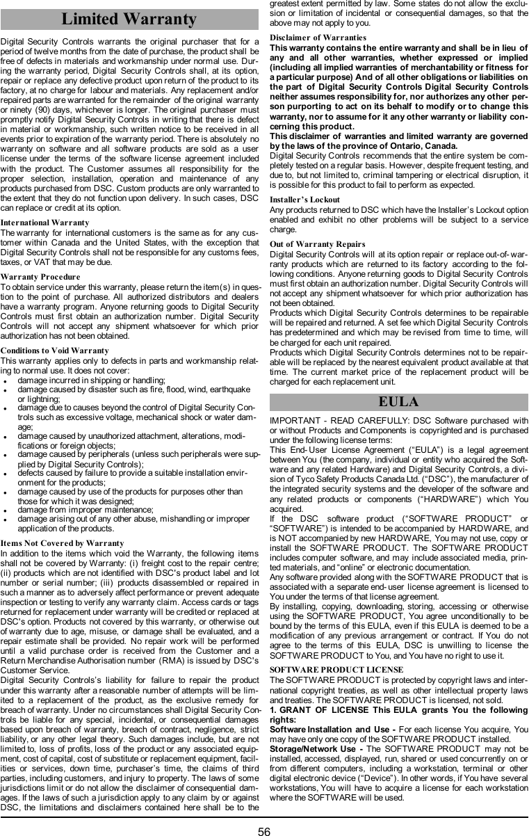
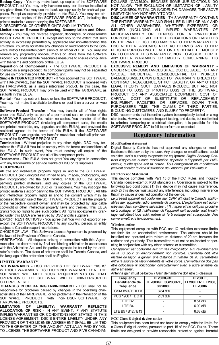
![interference in a residential installation. This equipment generates usesand can radiate radio frequency energy and, if not installed and used inaccordance with the instructions, may cause harmful interference toradio communications. However, there is no guarantee that inter-ference will not occur in a particular installation. If this equipment doescause harmful interference to radio or television reception, which canbe determined by turning the equipment off and on, the user is encour-aged to try to correct the interference by one or more of the followingmeasures:lReorient or relocate the receiving antenna.lIncrease the separation between the equipment and receiver.lConnect the equipment into an outlet on a circuit different from thatto which the receiver is connected.lConsult the dealer or an experienced radio/TV technician for helpCAN ICES-3 (B) / NMB-3 (B)TL2803G(R) E - EU /3G2080(R) E-EU/TL280(R)E LE2080(R)/TL280LE(R)FCC ID:F5316TL2803GRE FCC ID:F5317TL280LERIC: 160A-TL2803GRE IC:160A-TL280LERNotes for EN50131-1:2006/A1:2009 Compliant installations:Models TL2803G(R) E- EU/3G2080(R) E- EU/TL280(R) E are an SPTType Y - the module is mounted within CIE or PS housing and itreceives power from the compatible CIE or Power Supply source thatare in compliance with EN50131- 6:2008 Type A requirements for aGrade 2, Class II application. This product has no replacement partsand software programmable options are accessible at level 3 (installermode), section [851].The TL2803G(R)E-EU/3G2080(R)E- EU/TL280(R)E connects to com-patible DSC alarm control panels using the DSC proprietary serialinterface and protocol PC-Link (converted also to RS- 422). The mod-ule operates in pass-through mode and it does acknowledge the alarmto the compatible control panel after an acknowledgement has beenreceived from the compatible alarm receiver.1. The TL2803G(R)E-EU/3G2080(R)E-EU/TL280(R)E module ismonitored by the control panel and it is programmed via the pro-gramming menu (* 8, section [851] in the control panel. Theinterface is connected to the PC-Link bus as shown in the dia-gram included in this manual.2. The HSPA 3G Cellular path is immune to conducted and radi-ated RF fields with levels up to 10V/m as tested per EN50130- 4Standard.3. The TL2803G(R)E-EU/3G2080(R)E-EU/TL280(R)E moduleconforms with radiated emissions levels for Class B equipmentas per standards EN61000- 6-3/EN55022/CISPR22.4. The TL2803G(R)E-EU/3G2080(R)E-EU/TL280(R)E moduleuses AES128 encryption and heartbeat supervision for HSPA3G Cellular communication paths and it meets security levelsS2 as per EN50136-2:2013. It also uses authentication for eachmessage exchanged with the compatible receiver equipment atARC and it meets level I2 for information security.5. The 3G2080(R)E-EU module has only one communicationpath:HSPA 3G Cellular communication path using900/1800/2100MHz Public Cellular Network. The HSPA 3G Cel-lular communication path that can be used in a standalone modein conjunction with a DSC alarm system (compatible DSCalarm control panel models: HS2128/064/032/016). The sup-ported ATS configuration is: custom category C.6. The TL280(R)E module has only one communication path: Eth-ernet communication path using Internet. The communicationpath that can be used in a standalone mode in conjunction with aDSC alarm system (compatible DSC alarm control panel mod-els: HS2128/064/032/016). The supported ATS configuration is:custom category C.7. The TL2803G(R)E-EU module has two communication paths:HSPA 3G Cellular communication path using900/1800/2100MHz Public Cellular Network and Ethernet com-munication path using Internet. The communication paths canbe used in a standalone mode in conjunction with a DSC alarmsystem (compatible DSC alarm control panel models:HS2128/064/032/016). The supported ATS configuration is: cus-tom category C.8. TL2803G(R)E-EU/3G2080(R)E-EU/TL280(R)E has beentested for compliance in conjunction with the following applic-able standards: EN50136-1:2012, EN50136- 2:2013, EN50131-10:2014, ATS configuration: C.For EN50131- 1:2006/A1:2009 compliant installations, the following pro-gramming options shall be set as described.Supervision Heartbeat: shall be set to 180 secondsNOTE: The compatible receiver at ARC location shall have super-vision window programmed for 180 seconds. TL2803G (R) E-EU/3G2080 (R) E- EU/TL280 (R) E has been certified byTELEFICATION in accordance with EN50131- 1:2006/A1:2009,EN50131-10:2014 requirements for Grade 2, Class II and EN50136-2:2013 Configuration: CATS Custom Category C LevelEN50136-1:2012 Annex D TableD.1 D3EN50136-1:2012 Annex D TableD.2 M3EN50136-1:2012 Annex D TableD.3 T4EN50136-1:2012 Annex D TableD.4A4 (Depending on cellular carrierused)EN50136-1:2012 Annex D TableD.5S2 (use AES- 128 andauthentication/sequentialinformation in each messagetransmitted to the SG receiver)EN50136-1:2012 Annex D TableD.6 I2 (use AES-128 encryption)EN50136-1:2012 Table 1Use single communication path formodels 3G2080(R)E- EU (cellularnetwork), TL280 (R) E (Ethernetport) and two communicationpaths for model TL2803G(R)E- EU(cell/Ethernet).EN50136-1:2012 Table 4 ATS failure reported to ARCEN50136-1:2012 Table 5ATS failure reported to AS (DSCcompatible control panelHS2128/HS2064/HS2032/HS2016)EN50136-1:2012 Table 6 There is no recording ofavailability failureEN50136-2:2013 Table 1 No logging function providedEN50136-2:2013 Table 2 No memory provided for loggingfunctionEN50136-2:2013 Table 3 ATS failure reported to ARC+HUHE\ '6& GHFODUHV WKDW WKLV GHYLFH LV LQ FRPSOLDQFH ZLWK WKH HVVHQWLDOUHTXLUHPHQWVDQGRWKHUUHOHYDQWSURYLVLRQVRI'LUHFWLYH(&7KH FRPSOHWH 577( 'HFODUDWLRQ RI &RQIRUPLW\ FDQ EH IRXQG DWKWWSZZZGVFFRPOLVWLQJVBLQGH[DVS[&=( '6& MDNR Y¿UREFH SURKODģXMH ŀH WHQWR Y¿UREHN MH Y VRXODGX VH YģHPLUHOHYDQWQ¯PLSRŀDGDYN\VPÝUQLFH(&'$1'6&HUNO¨UHUKHUYHGDWGHQQHNRPSRQHQWHQRYHUKROGHUDOOHYLNWLJHNUDYVDPWDQGUHEHVWHPPHOVHUJLWWLGLUHNWLY(&'87+LHUELMYHUNODDUW'6&GDW GLWWRHVWHO LQRYHUHHQVWHPPLQJLV PHWGHHLVHQHQEHSDOLQJHQYDQULFKWOLMQ(&),1'6&YDNXXWWDDODLWWHHQW¦\WW¦Y¦QGLUHNWLLYLQ(&ROHQQDLVHWYDDWLPXNVHW)5(3DUOD SU«VHQWH'6& G«FODUHTXHFH GLVSRVLWLI HVWFRQIRUPH DX[H[LJHQFHVHVVHQWLHOOHVHWDXWUHVVWLSXODWLRQVSHUWLQHQWHVGHOD'LUHFWLYH(&*(5+LHUGXUFKHUNO¦UW'6&GD¡GLHVHV*HU¦WGHQHUIRUGHUOLFKHQ%HGLQJXQJHQXQG9RUUDXVHW]XQJHQGHU5LFKWOLQLH(&HQWVSULFKW*5(˂˜˞˱ˬ˲˭˞ˮ˹˪˱ˬ˯ˤ'6&ˡˤ˨˻˪ˢ˦˹˱˦˞˲˱˛ˤ˰˲˰˧ˢ˲˛ˢ˜˪˞˦˰˺˩˳˶˪ˤ˩ˢ˱˦˯ˬ˲˰˦˻ˡˤ˯˞˭˞˦˱˛˰ˢ˦˯˧˞˦˩ˢ˹˨ˢ˯˱˦˯˙˨˨ˢ˯˰˴ˢ˱˦˧˚˯˞˪˞˳ˬˮ˚˯˱ˤ˯ˍˡˤˠ˜˞˯(&,7$ &RQ OD SUHVHQWH OD 'LJLWDO 6HFXULW\ &RQWUROV GLFKLDUD FKH TXHVWR SURGRWWR ªFRQIRUPH DL UHTXLVLWL HVVHQ]LDOL HG DOWUH GLVSRVL]LRQL ULOHYDQWL UHODWLYH DOOD 'LUHWWLYD&(125'6&HUNO¨UHUDWGHQQHHQKHWHQHULVDPVYDUPHGGHJUXQQOHJJHQGHNUDYRJºYULJHUHOHYDQWHNUDYLGLUHNWLY()32/'6&RĝZLDGF]DľHXU]ÇG]HQLHMHVWZ]JRGQRĝFL]]DVDGQLF]\PLZ\PDJDQLDPLRUD]SR]RVWDĄ\PLVWRVRZQ\PLSRVWDQRZLHQLDPL'\UHNW\Z\:(3253RUHVWHPHLRD'6&GHFODUDTXHHVWHHTXLSDPHQWRHVW£HPFRQIRUPLGDGHFRP RV UHTXLVLWRV HVVHQFLDLV H RXWUDV GHWHUPLQD©·HV UHOHYDQWHV GD 'LUHFWLYD(&63$3RUODSUHVHQWH'6&GHFODUDTXHHVWHHTXLSRHVW£HQFRQIRUPLGDGFRQORVUHTXLVLWRVHVHQFLDOHV\RWURVUHTXLVLWRVUHOHYDQWHVGHOD'LUHFWLYD(&6:('6&EHNU¦IWDUK¦UPHGDWWGHQQDDSSDUDWXSSI\OOHUGHY¦VHQWOLJDNUDYHQRFKDQGUDUHOHYDQWDEHVW¦PPHOVHUL'LUHNWLYHW(&UL/ULC Installation RequirementsNOTE: For equipment used at the protected premises and intended tofacilitate IP communications (hubs, routers, NIDs, Digital SubscriberLine (DSL), cable modems), 24 hour backup power is required. Wheresuch cannot be facilitated, a secondary (back-up) communication chan-nel is required.Domain Name Service (DNS) programming is not permitted inUL1610 listed systems.Technical SpecificationsThe input voltage to the Communicator can be drawn from the Under-writers Laboratories/Underwriters Laboratories Canada (UL/ULC) lis-ted control panel.58](https://usermanual.wiki/Tyco-Safety-Canada/17TL280LER/User-Guide-3446153-Page-58.png)
![Notes for using Private, Corporate, and High Speed Data Networks:Network access and domain access policies shall be set to restrictunauthorized network access, and spoofing or Denial of Service (DoS)attacks. Select an Internet Service Provider (ISP) that has redundantservers/systems, back-up power, routers with firewalls enabled, andmethods to identify and protect against DoS attacks (e.g., via spoofing).Notes for using Public Switched and Cellular Data Networks:Communication channels shall be facilitated such that the com-municator will restrict unauthorized access, which could otherwisecompromise security. The communicator shall be located in a securedarea.• For ULC Residential Fire and Burglary applications the TL2803G(R)E/3G2080(R)E/TL280(R)E/LE2080(R)/TL280LE(R) can be usedas primary communication channel via either cellular or Ethernet or asa back-up in conjunction with the Digital Alarm Communicator Trans-mitter (DACT). Test transmission every 24 hours shall be enabled oneach channel.• For ULC Commercial Fire and Burglary applications the TL2803G(R)E/3G2080(R)E/TL280(R)E/LE2080(R)/TL280LE(R) can be usedas a passive communication module with the following security levels:lP1 (each channel cellular or Ethernet is independent)lP2 (cellular and Ethernet in back-up configuration, panel section[851][005] toggle option [5] OFF).lP3 (cellular and Ethernet in redundant configuration, panel section[851][005] toggle option [5] ON).The communicator can also be used as an active communication sys-tem with the security levels A1- A4 (each channel cellular or Ethernetindependent or together in a back-up/redundant configuration). For act-ive line security systems AES128 bit encryption shall be enabled (atthe monitoring station receiver) and the supervision heartbeat rate shallbe set as 90 seconds (panel section [851][004] = 005A/90). The super-vision window at the Signal Receiver Center (SRC)'s receiver shall beprogrammed as maximum of 180 (00B4/180) seconds.• For UL Residential Fire and Burglary applications the TL2803G(R)E/3G2080R/TL280(R)E/LE2080(R)/TL280LE(R) can be used asthe primary communication channel via either cellular or Ethernet, oras a back-up in conjunction with the DACT (30 day test transmission isrequired on each channel).• For UL Commercial Burglaryapplications the TL2803G (R) E/3G2080R / TL280(R)E / LE2080(R) / TL280LE(R) can be used asdual signalling line communication system (cellular and Ethernet chan-nels used in redundant configuration), standard line security and asencrypted line security.• The supervision heartbeat shall be enabled (panel section [851][005]toggle option [1] (Ethernet) and/or toggle option [2] (cellular) shall beON), toggle option [3] (supervision type) shall be ON and the super-vision heartbeat rate shall be selected as 135 (0087/135) seconds.Option [004] = 0087. The supervision window at the supervising stationshall be maximum 200 (00C8/200) seconds. For encrypted line secur-ity systems the encryption AES128 bit shall be enabled at the mon-itoring station receiver.• For UL Commercial Burglary installations, the TL2803G (R)E/3G2080(R) E/TL280(R) E/LE2080(R) /TL280LE(R) is listed as aprimary (sole) communication means (heartbeat must be enabled) orfor supplementary (back- up) use in conjunction with a Plain Old Tele-phone Service (POTS) line dialer. When the heartbeat transmissionover the Ethernet or cellular network is enabled, using the TL2803G(R)E/3G2080(R) E/TL280(R) E with a compatible control unit listed forstandard/encrypted line security, it can provide line security for thealarm system over the primary line.• The TL2803G(R) E/3G2080(R) E/TL280(R) E/LE2080(R) /TL280LE(R) is also suitable to be used with a compatible control unit listed fordual line security transmission when used in conjunction with a DACTor a Public Switched Data Network (PSDN) transmitter, where thePSDN provides the line security and is the primary line. In this mode,alarm signals are required to be sent simultaneously over both com-munication methods.59](https://usermanual.wiki/Tyco-Safety-Canada/17TL280LER/User-Guide-3446153-Page-59.png)
![© 2017 Tyco Security Products. All Rights Reserved.Tech Support: 1-800-387-3630 (Canada & U.S.) or 905-760-3000www.dsc.comThe trademarks, logos, and service marks displayed on this document are registered in the United States [or other countries]. Any misuse of thetrademarks is strictly prohibited and Tyco will aggressively enforce its intellectual property rights to the fullest extent of the law, including pursuitof criminal prosecution wherever necessary. All trademarks not owned by Tyco are the property of their respective owners, and are used withpermission or allowed under applicable laws.Product offerings and specifications are subject to change without notice. Actual products may vary from photos. Not all products include all fea-tures. Availability varies by region; contact your sales representative.29009549R002](https://usermanual.wiki/Tyco-Safety-Canada/17TL280LER/User-Guide-3446153-Page-60.png)