Tyco Safety Canada 17TL280LER Cellular Alarm Communicator User Manual My
Digital Security Controls Ltd. Cellular Alarm Communicator My
Users Manual

TL280LE(R)
Internet and LTE/HSPA Dual-Path Alarm
Communicator
LE2080(R)
LTE/HSPA Alarm Communicator
3G2080(R)E
Cellular Alarm Communicator
TL2803G(R)E
Internet and HSPA Dual-Path Alarm Communicator
TL280(R)E
Internet Alarm Communicator
Installation Manual v5.1
WARNING: This manual contains information on limitations regarding product use and
function and information on the limitations as to the liability of the manufacturer. The
entire manual should be carefully read.
PLEASE NOTE THAT NOT ALL MODELS AND FEATURES LISTED ARE AVAILABLE IN
ALL MARKETS.

Table of Contents
Table of Contents 2
WARNING: Installer please read carefully 4
General 5
IMPORTANT 5
Safety Information 5
Model Information 5
Panel Mounting 6
Features 6
Technical Specifications 6
Ratings Compatibility 7
Pre Installation Configuration 7
Encryption 7
Communicator Installation Configuration 8
Installing the Ethernet Cable (TLXXXX Models Only) 8
Inserting and Removing the SIM Card 8
Running the RS-232 Cable (R models only) 8
Installing Communicator in Panel 8
Installing Communicator with HS2016, HS2032, HS2064, and HS2128 Panel 8
Communicator Placement Test 12
Cellular Communicators Models Only 12
Cellular Signal Strength Display - LCD Keypad only 12
Initial Panel Programming 13
Keypad Data Display 13
Entering HEX values at keypad 13
Entering ASCII Characters at keypad 13
HS2016/2032/2064/2128 Initial Programming 13
Activating the Communicator with C24 Communications 13
SMS Command and Control 13
SMS Commands 14
Communicator Status LEDs 14
Yellow Trouble LED 14
Panel Supervision Trouble (2 Flashes) 14
SIM Lock Trouble (4 Flashes) 15
Cellular Trouble (5 Flashes) 15
Ethernet Trouble (6 Flashes) 15
Receiver Not Available (7 Flashes) 15
Receiver Supervision Trouble (8 Flashes) 15
FTC Trouble (9 Flashes) 15
Module Configuration Trouble (12 Flashes) 15
Red Network Connection Status LED 15
(Green LED 1) (Green LED 2) and (Yellow LED) Signal Strength 15
Network Activity LEDs - Red and Green(TL2803G(R)E / TL280LE(R) only) 16
Communicator Troubleshooting 16
Ethernet/Cellular Programming Options 18
System Options 18
Programming Options 20
Communications Reporting Codes 23
2

System Test Options 23
Ethernet Receiver 1 Options 25
Ethernet Receiver 2 Options 25
Ethernet Options 26
Cellular Receiver 1 Options 27
Cellular Receiver 2 Options 27
Cellular Options 28
SMS Event Notification/Command and Control Options 29
External Event Label Programming 35
Receiver Diagnostic Testing 38
System Information (Read Only) 38
System Reset Defaults 42
Ethernet Cellular Programming Worksheets 43
System Options 43
Programming Options 43
System Test Options 44
Ethernet Receiver 1 Options 44
Ethernet Receiver 2 Options 44
Ethernet Options 44
Cellular Receiver 1 Options 44
Cellular Receiver 2 Options 45
Cellular Options 45
Command and Control Options 45
External Event Label Programming 50
Receiver Diagnostic Testing 54
System Information (Read Only) 55
System Reset Defaults 55
Limited Warranty 56
EULA 56
Regulatory Information 57
3

WARNING: Installer please read
carefully
Note to Installers
The warnings on this page contain vital information. As the only indi-
vidual in contact with system users, it is the installer’s responsibility to
bring each item in this warning to the attention of all users of this sys-
tem.
System Failures
This system has been carefully designed to be as effective as possible.
There are circumstances, however, involving fire, burglary, or other
types of emergencies where it may not provide protection. Any alarm
system of any type may be compromised deliberately or may fail to
operate as expected for a variety of reasons. Some, but not all, of the
reasons may be:
Access by Intruders
Intruders may enter through an unprotected access point, circumvent a
sensing device, evade detection by moving through an area of insuf-
ficient coverage, disconnect a warning device, or interfere with or pre-
vent the proper operation of the system.
Component Failure
Although every effort has been made to make this system as reliable
as possible, the system may fail to function as intended due to the fail-
ure of a component.
Compromise of Radio Frequency (Wireless) Devices
Signals may not reach the receiver under all circumstances which
could include metal objects placed on or near the radio path or delib-
erate jamming or other inadvertent radio signal interference.
Criminal Knowledge
This system contains security features which were known to be effect-
ive at the time of manufacture. It is possible for persons with criminal
intent to develop techniques which reduce the effectiveness of these fea-
tures. It is important that the security system be reviewed periodically
to ensure that its features remain effective and that it is updated or
replaced if it is found that it does not provide the protection expected.
Failure of Replaceable Batteries
This system’s wireless transmitters have been designed to provide
several years of battery life under normal conditions. The expected bat-
tery life is a function of the device environment, usage, and type. Ambi-
ent conditions such as high humidity, high or low temperatures, or
large temperature fluctuations may reduce the expected battery life.
While each transmitting device has a low battery monitor which iden-
tifies when the batteries need to be replaced, this monitor may fail to
operate as expected. Regular testing and maintenance will keep the
system in good operating condition.
Inadequate Installation
A security system must be installed properly in order to provide
adequate protection. Every installation should be evaluated by a secur-
ity professional to ensure that all access points and areas are covered.
Locks and latches on windows and doors must be secure and operate
as intended. Windows, doors, walls, ceilings and other building mater-
ials must be of sufficient strength and construction to provide the level
of protection expected. A reevaluation must be done during and after
any construction activity. An evaluation by the fire and/or police depart-
ment is highly recommended if this service is available.
Inadequate Testing
Most problems that would prevent an alarm system from operating as
intended can be found by regular testing and maintenance. The com-
plete system should be tested weekly and immediately after a break-in,
an attempted break- in, a fire, a storm, an earthquake, an accident, or
any kind of construction activity inside or outside the premises. The
testing should include all sensing devices, keypads, consoles, alarm
indicating devices, and any other operational devices that are part of the
system.
Insufficient Time
There may be circumstances when the system will operate as inten-
ded, yet the occupants will not be protected from an emergency due to
their inability to respond to the warnings in a timely manner. If the sys-
tem is remotely monitored, the response may not occur in time to pro-
tect the occupants or their belongings.
Motion Detectors
Motion detectors can only detect motion within the designated areas as
shown in their respective installation instructions. They cannot dis-
criminate between intruders and intended occupants. Motion detectors
do not provide volumetric area protection. They have multiple beams of
detection and motion can only be detected in unobstructed areas
covered by these beams. They cannot detect motion which occurs
behind walls, ceilings, floor, closed doors, glass partitions, glass doors
or windows. Any type of tampering whether intentional or unintentional
such as masking, painting, or spraying of any material on the lenses,
mirrors, windows or any other part of the detection system will impair
its proper operation.
Passive infrared motion detectors operate by sensing changes in tem-
perature. However their effectiveness can be reduced when the ambi-
ent temperature rises near or above body temperature or if there are
intentional or unintentional sources of heat in or near the detection area.
Some of these heat sources could be heaters, radiators, stoves, bar-
becues, fireplaces, sunlight, steam vents, lighting and so on.
Power Failure
Control units, intrusion detectors, smoke detectors and many other
security devices require an adequate power supply for proper oper-
ation. If a device operates from batteries, it is possible for the batteries
to fail. Even if the batteries have not failed, they must be charged, in
good condition and installed correctly. If a device operates only by AC
power, any interruption, however brief, will render that device inop-
erative while it does not have power. Power interruptions of any length
are often accompanied by voltage fluctuations which may damage elec-
tronic equipment such as a security system. After a power interruption
has occurred, immediately conduct a complete system test to ensure
that the system operates as intended.
Security and Insurance
Regardless of its capabilities, an alarm system is not a substitute for
property or life insurance. An alarm system also is not a substitute for
property owners, renters, or other occupants to act prudently to prevent
or minimize the harmful effects of an emergency situation.
Smoke Detectors
Smoke detectors that are a part of this system may not properly alert
occupants of a fire for a number of reasons, some of which follow. The
smoke detectors may have been improperly installed or positioned.
Smoke may not be able to reach the smoke detectors, such as when
the fire is in a chimney, walls or roofs, or on the other side of closed
doors. Smoke detectors may not detect smoke from fires on another
level of the residence or building.
Every fire is different in the amount of smoke produced and the rate of
burning. Smoke detectors cannot sense all types of fires equally well.
Smoke detectors may not provide timely warning of fires caused by
carelessness or safety hazards such as smoking in bed, violent explo-
sions, escaping gas, improper storage of flammable materials, over-
loaded electrical circuits, children playing with matches, or arson.
Even if the smoke detector operates as intended, there may be cir-
cumstances when there is insufficient warning to allow all occupants to
escape in time to avoid injury or death.
Telephone Lines
If telephone lines are used to transmit alarms, they may be out of ser-
vice or busy for certain periods of time. Also an intruder may cut the
telephone line or defeat its operation by more sophisticated means
which may be difficult to detect.
Warning Devices
Warning devices such as sirens, bells, horns, or strobes may not warn
people or waken someone sleeping if there is an intervening wall or
door. If warning devices are located on a different level of the residence
or premise, then it is less likely that the occupants will be alerted or
awakened. Audible warning devices may be interfered with by other
noise sources such as stereos, radios, televisions, air conditioners,
other appliances, or passing traffic. Audible warning devices, however
loud, may not be heard by a hearing-impaired person.
4
General
IMPORTANT
This installation manual shall be used in conjunction with the control panel. All the safety instructions spe-
cified within that manual shall be observed. The control panel is referenced as the “panel” throughout this
document. This installation guide provides the basic wiring, programming and troubleshooting inform-
ation.
The HSPA(3G)/dual-path alarm communicator is a fixed, wall-mounted unit, and shall be installed in the
location specified in these instructions.The equipment enclosure must be fully assembled and closed,
with all the necessary screws/tabs, and secured to a wall before operation. Internal wiring must be
routed in a manner that prevents:
lExcessive strain on wire and on terminal connections,
lInterference between power limited and non power limited wiring,
lLoosening of terminal connections, or
lDamage of conductor insulation.
WARNING: Never install this equipment during a lightning storm!
Safety Information
The installer must instruct the system user on each of the following:
lDo not attempt to service this product. Opening or removing covers may expose the user to dan-
gerous voltages or other risks.
lAny servicing shall be referred to service persons only.
lUse authorized accessories only with this equipment.
lDo not stay close to the equipment during device operation.
lDo not touch the external antenna.
Model Information
This manual covers the following models of alarm communicators:
Models TL2803GRE,TL2803GE,3G2080RE, 3G2080E, TL280RE and TL280E are for North Amer-
ica and cover the following bands: 850 / 1900MHz.
Models TL2803GRE- EU ,TL2803GE- EU ,3G2080RE- EU and 3G2080E- EU are for Europe/In-
ternational and cover the following bands: 900/1800 MHz.
Models TL280LER ,TL280LE,LE2080R,LE2080 are for North America and support LTE bands B2,
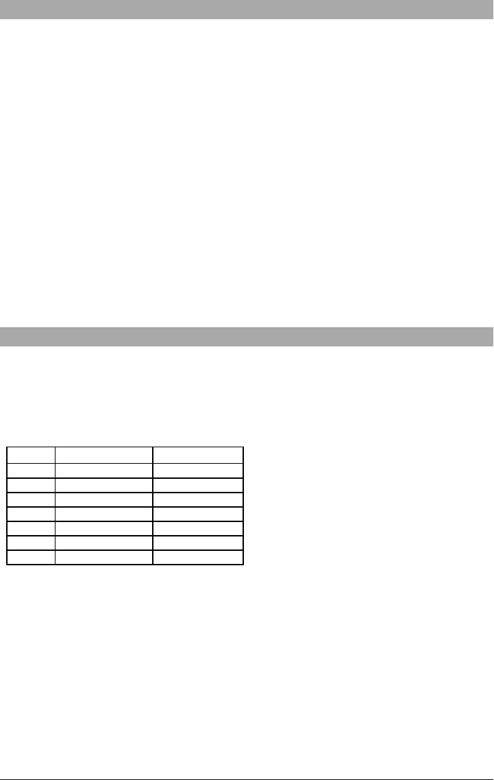
B4, B5, B12 and B13 and WCDMA bands B2 and B5.
Band Transmit Band (Tx) Receive Band (Rx)
LTE B2 1850 - 1910 MHz 1930 - 1990 MHz
LTE B4 1710 - 1755 MHz 2110 - 2155 MHz
LTE B5 824 - 849 MHz 869 - 894 MHz
LTE B12 698 - 716 MHz 728 - 746 MHz
LTE B13 777 - 787 MHz 746 - 756 MHz
UMTS B2 1850 - 1910 MHz 1930 - 1990 MHz
UMTS B5 824 - 840 MHz 869 - 894 MHz
References to model names TL280(R)E,TL2803G(R)E, 3G2080(R)E,TL280LE(R) and LE2080(R)
throughout this manual apply to all specified models unless stated differently. Models ending in “R”
include a built-in RS-232 interface for connecting to local third party applications.
The TL280(R) E/TL2803G(R)E/3G2080 (R) E/TL280LE(R) /LE2080(R supports integration over cel-
lular/IP, available with licensed 3rd party product solutions. Specific programming for the related pro-
gramming sections is to be provided by the 3rd party. A current list of compatible 3rd party solutions can
be found at www.dsc.com.
3G2080(R)E: Is a HSPA(3G) cellular alarm communicator that sends alarm communication to Sur- Gard
System I-IP, II, III (SG-DRL3IP), IV (SG-DRL4IP), and 5 (SG- DRL5IP) central station receivers via a
HSPA(3G)/GPRS digital cellular network. TL2803G(R)E: Is a dual-path HSPA(3G) Ethernet alarm com-
municator that sends alarm communication to Sur- Gard System - IPI, II, III, IV, and 5 central station
receivers through Ethernet/Internet or a HSPA(3G)/GPRS digital cellular network.
TL280(R)E: Is an Ethernet alarm communicator that sends alarm communication to Sur-Gard System I-
IP, II, III (SG- DRL3IP), IV (SG- DRL4IP), and 5 (SG- DRL5IP) central station receivers via Eth-
ernet/Internet.
5

LE2080(R) : is an LTE (4G) cellular alarm communicator with HSPA(3G) fallback support that sends
alarm communications to Sur- Gard System I- IP, II, III (SG- DRL2IP, IV (SG- DRL4IP) and 5 (SG-
DRL5IP) central station receivers via an LTE(4)/HSPA(3G) digital cellular network.
TL280LER: Is a dual path LTE (4G) Ethernet alarm communicator that sends alarm communications to
Sur-Gard System I-IP, II, III (SG-DRL3IP, IV (SG-DRL4IP) and 5 (SG-DRL5IP) central station receivers
via Ethernet/Internet or a LTE(4)/HSPA(3G) digital cellular network.
The communicator can be used as either a backup or primary communicator. The communicator sup-
ports Internet Protocol (IP) transmission of panel and communicator events over Ethernet/Internet
and/or HSPA/GPRS.
The cellular performance of the LE2080(R), TL280LE(R), 3G2080 (R) E or TL2803G (R) E com-
municators depend greatly on the LTE(4G)/HSPA(3G) network coverage in the local area.
Optional antenna kits (GS-15ANTQ, GS-25ANTQ, GS-50ANTQ) are available from DSC to improve sig-
nal strength as required.
NOTE: Prior to installation, confirm with the local service provider that the LTE(4G)/HSPA(3G) network
is available and active in the area where the communicator will be installed, and that radio signal
strength (CSQ) is adequate.
Panel Mounting
The following communicators are compatible with HS2016, HS2016-4, HS2032, HS2064, and HS2128
panels:
l3G2080(R)E (HSPA(3G)/GPRS only)
lTL2803G(R)E (Ethernet/Internet + HSPA(3G)/GPRS dual-path)
lTL280(R)E (Ethernet/Internet only)
lLE2080(R) (LTE(4)/HSPA(3G) only)
lTL280LE(R) (Ethernet/Internet + LTE(4)/HSPA(3G))
Features
l128-bit AES encryption via cellular and Ethernet/Internet (NIST validation cert. number 2645).
lBack up or primary cellular alarm communication.
lAutomatically switches to 2G (EDGE/GPRS) if HSPA(3G) service is not available.
lEthernet LAN/WAN 10/100 BASE-T (TL2803G(R)E and TL280(R)E only).
lFully redundant Ethernet/Internet and cellular dual-path alarm communication (TL2803G(R)E only).
lFull event reporting to central station.
lIndividual Internet and/or cellular periodic test transmission.
lIntegrated call routing.
lVisual Verification (Requires Sur-Gard System 5 Receiver)
lRemote firmware upgrade capability of the communicator and panel firmware via Ethernet and/or cel-
lular.
lPanel remote uploading/downloading support via cellular and Ethernet/Internet.
lPC-LINK connection.
lProgrammable labels.
lSIA and Contact ID (CID) formats supported.
lSignal strength and trouble display LEDs.
lSupervision heartbeats sent via cellular and Ethernet/Internet.
lThird party integration over cellular/IP. The product supports third party application via serial (R-mod-
els only), cellular and, Ethernet. Refer to third-party application documentation for more information.
Technical Specifications
The TL2803G(R) E is also suitable to be used with a compatible control unit listed for dual line security
transmission when used in conjunction with a DACT or a Public Switched Data Network (PSDN) trans-
mitter, where the PSDN provides the line security and is the primary line. In this mode, alarm signals are
to be sent simultaneously over both communication methods.
6
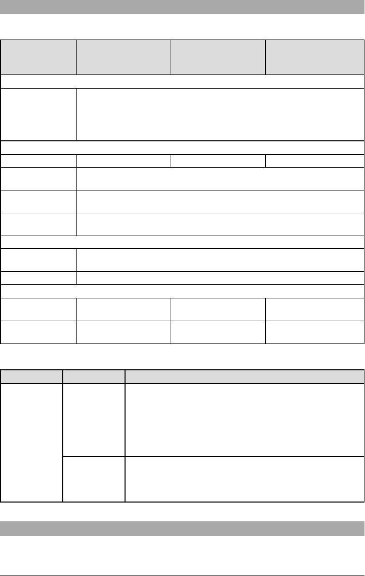
Ratings Compatibility
Table 1: Communicator Ratings
Model
3G2080(R)E /LE2080
(R)
Cellular only
TL280(R)E
Internet only
TL2803G(R)E/TL280LE
(R)
Internet and Cellular
Power Supply Ratings
Input Voltage
10.8-12.5 VDC
Power is supplied from the panel’s PC-Link header or PCL-422 module in remote
cabinet installations. In remote cabinet installations, the PCL-422 module located
with the communicator is powered by an HSM2204 or an HSM2300. Refer to the
PCL-422 installation sheet for details.
Current Consumption
Standby Current 90mA @ 13.66V 120mA @ 13.66V
Alarm (Transmitting)
Current 400mA @ 12V
Operating
Frequency 850MHz, 1900MHz
Typical Antenna
Gain 2dBi
Environmental Specifications
Operating
Temperature -10°C to 55°C
Humidity 5% ~ 93% relative humidity, non-condensing
Mechanical Specifications
Board Dimensions
(mm) 100 × 150 × 15 100 × 150 × 15
Weight (grams) with
bracket 310 320
Table 2: Compatible Receivers and Panels
Communicator Receiver/Panel Description
3G2080(R)E
LE2080(R)
TL2803G(R)E
TL280LE(R)
TL280(R)E
Receiver
lSur-Gard System I-IP Receiver, version 1.13+
lSur-Gard System II Receiver, version 2.10+
lSur-Gard SG-DRL3-IP, version 2.30+ (for Sur-Gard System III
Receiver)
lSur-Gard SG-DRL4-IP version 1.20+ (for Sur-Gard System IV
Receiver)
lSur-Gard SG-DRL5-IP version 1.00+ (for Sur-Gard System 5
Receiver)
Panel
lHS2016
lHS2016-4
lHS2032
lHS2064
lHS2128
NOTE: Enter [*][8][Installer Code][900] at keypad to view the panel version number.
Pre Installation Configuration
Encryption
The communicator uses 128 Bit AES encryption. Encryption can only be enabled from the monitoring sta-
tion receiver. Each receiver (Ethernet 1 and 2, cellular 1 and 2) can independently have encryption
7

enabled or disabled. When encryption is enabled, the central station will configure the device to encrypt
communications the next time the communicator module performs a communication to that receiver.
NOTE: Packets will start being encrypted only after the next event is sent to that receiver, or if the unit is
restarted.
Before leaving the installation site, the communicator TL2803G(R)E Ethernet line shall be
connected via an APPROVED (acceptable to the local authorities) Network Interface Device
(NID). All wiring shall be performed according to the local electrical codes.
Communicator Installation Configuration
This HSPA(3G)/dual-path alarm communicator shall be installed by service persons only (service person
is defined as a person having the appropriate technical training and experience necessary to be aware of
hazards to which that person may be exposed to in performing a task and can also take measures to min-
imize the risks to that person or other persons). The Communicator shall be installed and used within an
environment that provides the pollution degree max 2, overvoltages category II, in non- hazardous,
indoor locations only. This manual shall be used with the installation manual of the panel which is con-
nected to the communicator. All instructions specified within the panel manual must be observed.
All the local rules imposed by local electrical codes shall be observed and respected during installation.
Installing the Ethernet Cable (TLXXXX Models Only)
A Category 5 (CAT 5) Ethernet cable must be run from a source with Internet connectivity to the com-
municator module, inside the panel. The communicator end of the cable must be terminated with an
RJ45 plug, which will connect to the communicator’s RJ45 jack after the communicator is installed. All
requirements for installation of CAT5 Ethernet cable must be observed for correct operation of the com-
municator, including, but not limited to, the following:
lDo NOT strip off cable sheathing more than required for proper termination.
lDo NOT kink/knot cable.
lDo NOT crush cable with cable ties.
lDo NOT untwist CAT5 pairs more than ½ in. (1.2cm).
lDo NOT splice cable.
lDo NOT bend cable at right angles or make any other sharp bends.
NOTE: CAT5 specification requires that any cable bend must have a minimum 2 in. (5 cm) bend radius.
Maximum length of CAT 5 cable is 328 ft. (100 m).
Inserting and Removing the SIM Card
1. Remove the front cover of the panel to access SIM holder.
2. Remove power from the panel and disconnect the battery and telephone line.
3. On the SIM card holder push gently to slide the cover downwards to OPEN. This will unlatch the SIM
card holder on the top edge of the communicator PCB. (See Figure 3).
4. Tilt the top of the SIM card holder downwards to access the SIM card.
NOTE: The SIM can be damaged by bending or scratching contacts. Use caution when handling SIM
cards.
5. Insert or remove the SIM card, noting the orientation of the notches on the SIM card and the SIM
card holder.
6. When inserting a SIM card, insert the card in the proper orientation and gently push the SIM card
holder down and slide the holder as indicated by the arrow on SIM holder, to LOCK.
7. Reconnect the backup battery and telephone line, apply AC power to panel, and replace the panel
cover.
Running the RS-232 Cable (R models only)
When installing the communicator for use with 3rd party applications an RS-232 cable must be con-
nected between the 3rd party device and the communicator module.
NOTE: Maximum cable length for RS-232 cable is 8 ft. (2.4 m).
Please refer to the installation manual for the 3rd party device for wiring instructions.
Installing Communicator in Panel
Installing Communicator with HS2016, HS2032, HS2064, and HS2128 Panel
NOTE: Before installing communicator or inserting/removing SIM, ensure that system power is OFF and
telephone line is disconnected.
1. To assemble supplied mounting bracket, perform the following: (See Figure 1).
a. Remove the 4 white plastic standoffs from the bag provided with the communicator kit.
b. Insert the 4 standoffs through the back of the mounting bracket, into the holes at each corner.
(The antenna mounting tab should be facing away from you).
8
c. Place the bracket on a flat, solid surface. Hold the communicator component side up and orient
the 4 holes on the communicator with the 4 standoffs protruding from the bracket. Push the com-
municator firmly and evenly onto the standoffs until it is securely attached to the mounting
bracket.
d. Remove the panel front cover.
e. Remove and discard the circular knockout located in the top-right section of the panel. (This hole
will be used for connection of the supplied radio antenna).
f. Connect the supplied 5” (12.7 cm) antenna cable to the radio, by passing the connector through
the hole on back of the mounting bracket to the communicator board. Push the antenna con-
nector firmly into the socket on the cellular radio. (See Figure 3).
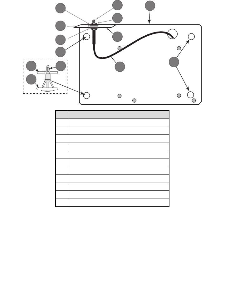
Figure 1: Communicator Mounting Bracket
10
4
1
2
8
3
7
65
11
9
9
8
Item Description
1 External Antenna Screw Thread
2 Brass Nut
3 Brass Washer
4 Nylon Washer (flat)
5 Antenna Mounting Tab
6 Nylon Washer with bushing (thicker flat washer)
7 Antenna Cable
8 Mounting Holes
9 Mounting Plate
10 Communicator Board
11 Stand Off
2. Install the Communicator into the panel:
a. Attach one end of the PC-LINK cable to the panel PCLINK_2 header on the panel (red wire
goes on the right-hand pin of the panel PCLINK_2 header (see Figure 3)).
b. Insert the assembled communicator into the panel.
NOTE: Ensure that the threaded antenna connection point is visible through the knockout hole
at the top right of the panel.
c. Place the nylon washer with bushing (thick flat washer) onto the threaded section of the antenna
cable. Insert the threaded section through the antenna mounting knockout hole at top right of
panel.
d. Place the second nylon washer (flat), followed by the brass washer and the brass nut, onto the
threaded section of the cable, outside the panel. Tighten the assembly by hand only (finger
tight only- do not over tighten the antenna assembly).
e. Locate the screw hole on the right side wall of the panel. See Figure 2 "screw". Line up the
assembled communicator with the right side wall of the panel and, using the screw provided,
9
secure the mounting bracket to the panel.
f. Attach the other end of the PC-LINK cable to the communicator (red wire goes on the right-
hand pin of the communicator PC-LINK header (See Figure 3)).
g. Using light pressure (finger tight only), attach the supplied white quad band whip antenna to the
threaded antenna connection point at top of the panel.
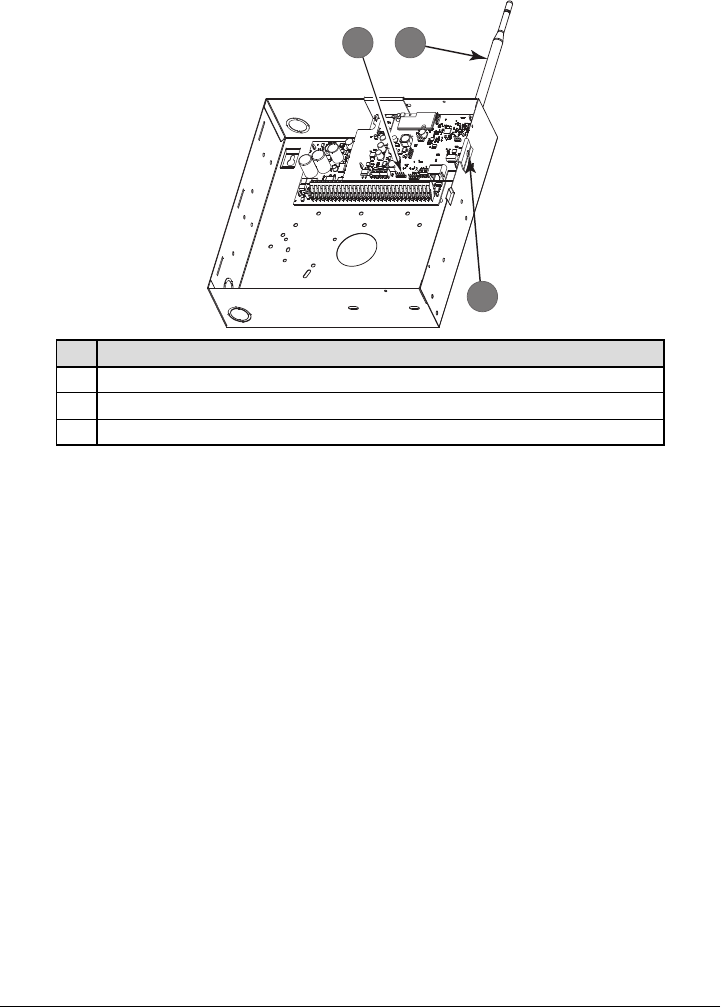
Figure 2: HS2016/2032/2064/2128 Control Panel
HS2016/2032/2064/2128
1 2
3
Item Description
1 PC-Link Cable Connector
2Quad Band Whip Antenna - Use light pressure to attach antenna finger tight only
3 Screw
WARNING! - 3G2080(R) E/TL2803G(R) E/LE2080(R)/TL280LE (R) modules are power limited.
Do not route any wiring over the circuit board. Maintain at least 1in. (25.4mm) separation
between circuit board and wiring. A minimum of ¼ in. (7mm) separation must be maintained
at all points between non-power limited wiring and power limited wiring.
3. To electrically connect the communicator to the panel, perform the following steps (See Figure 3).
a. Disconnect both AC power and battery connections from the panel, and disconnect telephone
line.
b. Confirm that the SIM card is inserted in the holder and locked.
4. Install Network Cable (TLXXXX models only). Route the CAT 5 Ethernet cable through back of the
panel and plug it into the communicator’s RJ45 jack.
NOTE: Before leaving the premises the Ethernet communication lines must first be connected to an
approved (acceptable to local authorities) type NID. All wiring shall be performed according to the
local electrical codes.
10
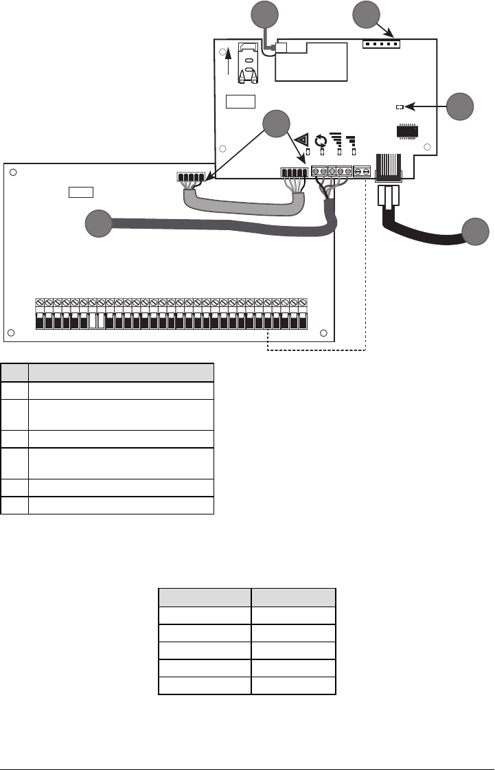
Figure 3: Communicator Wiring Diagram
AUDIO/DEFAULT
DSC
UA685
PC-LINK
PCLINK_2
COM
TL2803G(R)E
3G2080(R)E
TL280(R)E
TL280LE(R)
LE2080(R)
AC
AC Z1 COM Z2 Z3 COM Z4 Z5 COM Z6 Z7 COM Z8
AUX+
BELL +
PGM1 PGM3
RING
T-1
HS2016/2032/2064/2128
3G/LTE Radio
UA621
L
o
c
k
1
RJ-45
GRN
YEL
TIP
R-1
BLK
RED
AUX -
BELL -
EGND
TX+
GND
TX-
RX+
RX-
SHLD
SIM
PGM2 PGM4
4
1 2
3
5
6
Item Description
1 To External Antenna
2AUDIO/DEFAULT
Jumper pins 4 and 5 to reset
3 Network Link - Yellow
4From NID use only CAT5 supervised
maximum cable length 100m (328 feet)
5 RS-232 to third party device
6 RED Wire
Input Ratings:
l+10.8V ~ +12.5VDC
l90mA(3G2080(R)E)/120mA(TL2803G(R)E) standby;
l90mA (3G2080(R)E/ LE2080(R)
l120mA (TL2803G(R)E/TL280LE(R).
l400mA alarm
DSC Panel minimum power requirements:
l16.5 VAC 40 VA transformer
l12 VDC 7Ah battery
5. Install the RS-232 connections (R models only). If using the communicator with a 3rd party device,
wire the connections as per the table below:
Table 3: RS-232 Connections
3rd Party Device Communicator
TX RX+
Unused RX-
RX TX+
Unused TX-
GND GND
6. Perform the following steps for initial power on of the panel with communicator installed:
a. Reconnect the AC power, telephone line, and battery + connector to the panel.
(The communicator and panel will power up together).
b. Observe that the communicator’s red and yellow LEDs are flashing together while it initializes.
The red and yellow LEDs will continue to flash until the communicator has successfully
11
communicated to all programmed receivers. If this is the first time the communicator has been
powered up in the panel, the module willinitiate communications to C24 Communications to
request remote programming.
NOTE: During radio reset, the two green LEDs will flash alternately.
NOTE: Initialization may take several minutes to complete. Red and yellow LEDs will flash together dur-
ing initialization. Do not continue to next step until the red and yellow LEDs have stopped flashing.
(If only the yellow LED is flashing, there is a communicator trouble and the green LEDs are not
valid for communicator placement test). Correct trouble indicated by flashes on yellow LED before
continuing. (See Table 8 for troubleshooting assistance).
7. Perform the communicator placement test below.
8. Mount the panel in final location indicated by placement test.
Communicator Placement Test
Cellular Communicators Models Only
To confirm that the cellular antenna location is suitable for radio operation, perform the placement test as
follows:
NOTE: It might be necessary to relocate the panel or install an optional extension antenna during this pro-
cedure, if the radio signal strength is too low.
1. Confirm that the yellow LED on the communicator is not flashing. A flashing yellow LED indicates
trouble on the communicator. See Table 8 to troubleshoot and correct the cause of this trouble
before continuing to the next step.
2. Confirm that the strength of the radio signal on the yellow LED and the 2 green LEDs on the com-
municator meet or exceed the minimum signal level requirement. Minimum signal level: The yellow
LED is OFF and the green LED 1
(furthest from the yellow LED) is ON (i.e., not flashing) for the panel location to be acceptable. For
interpretation of receiver strength on LEDs, refer to the table “Radio Signal Strength” on page
10.
Cellular Signal Strength Display - LCD Keypad only
The cellular network signal strength can be checked on the keypad LCD screen by entering installer pro-
gramming section [850]. The LCD will indicate the SIM card activation status followed by up to five bars of
signal strength. This display will automatically update every three seconds. For the relationship between
signal strength bars, CSQ level, and signal level in dBm, refer to “Radio Signal Strength” on page
10.
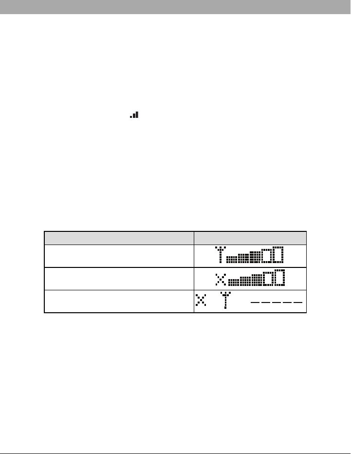
Table 4: Signal Strength Display
Description Display
SIM card active and current signal strength
SIM card inactive and current signal strength
Radio not registered
OR AND
NOTE: If the required signal strength is too low with the panel in its current location, the panel must be
relocated or an external antenna is required.
If required, the following cellular extension antenna kits are available to the installer:
lGS-15ANTQ - 4.57m (15’) internal antenna extension kit (suitable for interior mounting).
lGS-25ANTQ - 7.62m (25’) external antenna extension kit (suitable for interior/exterior mounting).
lGS-50ANTQ - 15.24m(50’) external antenna extension kit (suitable for interior/exterior mounting).
Specific instructions for the installation of the extension antenna are included with the kit. Observe all the
electrical safety instructions regarding the installation of the antenna. All the wiring of the equipment shall
be fully compliant with the local rules and regulations.
3. If required, install the antenna extension and perform the following steps to determine the best loc-
ation for placement of the antenna:
a. Disconnect the white whip antenna from the panel.
b. Attach one end of the antenna extension cable to the threaded antenna connector on the panel
and the other end to the external antenna.
12

4. Move the extension antenna to various locations while observing the two green LEDs on the panel.
a. Continue to reposition the extension antenna until it receives an acceptable (minimum one
green LED ON solid) signal strength.
NOTE: Minimum strength is: green LED 1 flashing and yellow LED off. If green LED 1 is
flashing, relocation should be considered.
b. Mount the supplied antenna extension bracket at the location that provides the best signal
strength.
5. Alternately, reposition the panel to improve signal strength. Dismount the panel and move it to
another location to achieve the required signal strength. If the panel is relocated to improve signal
strength, mount it in the new location.
6. When final panel/antenna location is determined, continue at the Initial Panel Programming sec-
tion.
NOTE: If the SIM card is not activated, placement test will indicate the signal strength of the nearest cel-
lular tower.
NOTE: In between displaying signal strength, the signal strength LEDs will flash alternately if an inactive
SIM card is used. The flashing indicates that the module is attempting to attach to the cellular net-
work and will only last briefly.
Initial Panel Programming
Keypad Data Display
lSection-Toggle Options: The number is displayed when toggle is ON and the number is not dis-
played when toggle is OFF. (e.g., toggle options displays: [--3--6--]. Options 3 and 6 are ON, all oth-
ers are OFF). Pressing keys 1 through 8 will alternately turn the toggle ON and OFF.
lHEX/Decimal Data: Values that are provided with two defaults, separated by a “/” character, use the
format: hexadecimal followed by decimal equivalent (e.g., default [0BF5/3061]). Hexadecimal num-
bers are shown, with all leading zeroes, to the full field length defined for the number.
Entering HEX values at keypad
To enter HEX values at the keypad, press the * key before entering the HEX value. (e.g., to enter “C” at
the keypad, press [*][3])
Entering ASCII Characters at keypad
1. Press [*] and use scroll buttons [<] [>] to display “ASCII Entry” on the LCD screen.
2. Press [*] to select ASCII entry mode.
3. Use the [<] [>] scroll keys to display the desired character and press [*] to save and exit ASCII.
4. Repeat the steps above to enter another ASCII character.
HS2016/2032/2064/2128 Initial Programming
For detailed information, refer to panel manual section ‘Alternate Communicator Set-up’. These sections
must be programmed at the panel keypad. Enter [*][8] [Installer Code] [Section Number]. Record
any values that are modified from their default, in the appropriate worksheets for the panel or com-
municator.
1. In panel section [377] ‘Communication Variables’, subsection [002] ‘Communication Delays’, sub-
subsection [1] ‘Communication Delay’, program 060 (seconds).
2. In panel section [382] ‘Communicator Option 3’ set option [5] ON
NOTE: If this option is OFF, the yellow status LED on the communicator will indicate ‘Panel Supervision
Trouble’ (2 flashes) and the unit can not be programmed via the PC-LINK cable.
Activating the Communicator with C24 Communications
Installation of the 3G2080(R)E / LE2080(R) or TL2803G(R)E / TL280LE(R) requires activation with C24
Communications in order to operate. Please contact the central station (C24 Communications Master
Reseller) to confirm the required steps to activate/program the communicator.
NOTE: NOTE: The SIM activation with the carrier can take several hours to complete. It is recom-
mended the activation be completed prior to arrival on the customer site to avoid possible install-
ation delays.
Once the SIM activation is complete, the communicator will automatically connect and download its pro-
gramming from C24 Communications.
SMS Command and Control
Certain functions can be performed on the alarm panel by remote, using SMS text messages. In addi-
tion, the system sends SMS messages to confirm commands. SMS programming options are accessed
13
through programming section [851].
The security system only responds to SMS messages sent from designated phone numbers (pro-
grammed in section [851]>[311]-[328]).
SMS Commands
lStay arm the system
lAway arm the system
lNight arm the system
lDisarm the system
lActivate command output 1
lActivate command output 2
lActivate command output 3
lActivate command output 4
lDeactivate command output 1
lDeactivate command output 2
lDeactivate command output 3
lDeactivate command output 4
lSystem status request
lAlarm memory request
lZone bypass
lZone unbypass
SMS text messages must be formatted as follows:
<function name><space><partition #><space><access code>
(e.g., Stay Arm partition 1 1234). Once the command is received and executed by the alarm system, a
confirmation text message is received.
NOTE: For more information about SMS commands and control functions, refer to the Neo 1.1 User
Manual.
Communicator Status LEDs
The communicator has four on-board LED indicators. These include one yellow trouble LED, one red
network connection status LED and two green signal strength LEDs. The LED meaning is described in
this section.
Yellow Trouble LED
This yellow LED will flash to indicate a trouble on the unit. The number of flashes indicates the type of
trouble. See the table below for the coded flashes and the conditions which willactivate the trouble status
LED.
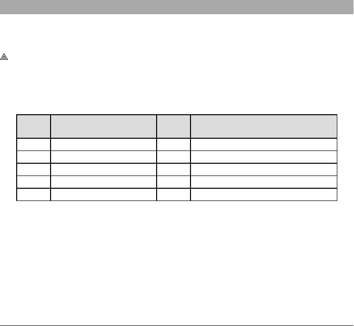
Table 5: Yellow Trouble Status LED
# of
Flashes Trouble # of
Flashes Trouble
2 Panel Supervision Trouble 8 Receiver Supervision Trouble
4 Not Applicable 9 FTC Trouble
5 Cellular Trouble 10 C24 Communications Configuration Failure
6 Ethernet Trouble 12 Module Configuration Trouble
7 Receiver Not Available Trouble
NOTE: Only the highest priority trouble (2 flashes is the highest priority trouble) is indicated. When this
trouble is restored, the next highest trouble will indicate, if present. This will continue until all
troubles have been cleared (yellow LED is not flashing).
The following paragraphs describe the conditions associated with the trouble indicated:
Panel Supervision Trouble (2 Flashes)
This trouble will be indicated when communication between the communicator module and the panel
fails. If the module can not communicate with the panel (e.g., loss of power to the panel) the com-
municator will send the ‘Panel Absent Trouble Event’ message to the central station receiver. When com-
munication returns, a ‘Panel Absent Restore Event’ is sent by the communicator to the central station
receiver. The reporting codes are ET0001 for trouble and ER0001 for restore. The panel absent event
always uses the primary receiver account code when communicating to the central station.
14

NOTE: The panel supervision trouble/restore are internally generated events by the communicator.
Trouble is generated if the communicator misses 6 polls. Trouble is restored on receipt of first poll
from the panel.
SIM Lock Trouble (4 Flashes)
This trouble occurs when the SIM lock feature has been enabled and the unit has been programmed
with the wrong PIN for the SIM card.
Cellular Trouble (5 Flashes)
This trouble is indicated for any of the following 4 conditions:
1. Radio Failure: Trouble is indicated after 8 failed attempts to communicate with the cellular radio.
2. SIM Failure: Trouble is indicated after 10 failed attempts to communicate with the SIM.
3. Cellular Network Trouble: Trouble is indicated for loss of the registration to the network provider.
4. Insufficient Signal Strength: Trouble is indicated if calculated average signal strength is too low.
(Both green LEDs are OFF). Trouble will clear when the calculated average signal strength is
above minimum (i.e., > CSQ 5).
NOTE: If Option [851][005] Bit 8 is Off, CSQ less than or equal to 4 will not trigger Cellular Trouble
Ethernet Trouble (6 Flashes)
This trouble is indicated when an Ethernet link between the transmitter and the local switch or router is
absent. This trouble will also be indicated if the unit fails to get Dynamic Host Control Protocol (DHCP) set-
tings from the DHCP server. (Not active if Ethernet receivers are not programmed).
Receiver Not Available (7 Flashes)
This trouble is indicated if the unit is not able to successfully initialize with any of the programmed receiv-
ers. Unprogrammed receivers are excluded. This trouble is also indicated if the cellular receiver APNs
have not been programmed in sections [205] and [215].
Receiver Supervision Trouble (8 Flashes)
This trouble is indicated when receiver supervision is enabled and communication between the com-
municator module and the receiver fails. Trouble is indicated if Ethernet 1 and/or cellular 1 is supervised
and does not receive a heartbeat from the receiver or if cellular is supervised and the unit does not
receive an acknowledgment to 4 heartbeats sent to the receiver.
FTC Trouble (9 Flashes)
This trouble is indicated when the unit fails to communicate module events to the central station. Trouble
is displayed after the unit has exhausted all communications attempts to all programmed receivers for
events generated by the communicator.
Module Configuration Trouble (12 Flashes)
This trouble is indicated when the system account code or the receiver account have not been pro-
grammed. Disabled receivers are excluded.
Red Network Connection Status LED
TL280(R)E / TL280LE(R) / TL2803G(R)E only
BLINKING: Indicates communications in progress.
lOnce quickly for outgoing Ethernet transmission.
lTwice quickly to indicate incoming Ethernet ACK/NACK.
OFF: This is the normal state of the red network connection status LED. There are no network con-
nection issues present.
ON: There is a problem with the Ethernet or the cellular network connection. LED will be ON if any of the
following occur: Ethernet cable is not connected, DHCP configuration times out, unit fails to get an IP
address from the cellular network, or Cellular connection has been reset.
(Green LED 1) (Green LED 2) and (Yellow LED) Signal Strength
NOTE: If the yellow LED is flashing, signal strength in table below is not valid.
See Table 8 for troubleshooting flashing yellow LED.
15
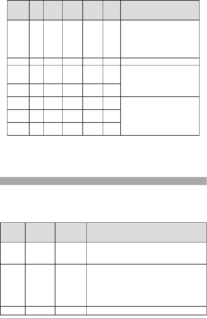
Table 6: Radio Signal Strength
Signal
Strength
CSQ
Level
Yellow
LED
Green
LED 2
Green
LED 1
Signal
Level
dBm
Action Required
Radio Not
Ready N/A N/A Alternate
Flashing
Alternate
Flashing N/A
If this status persists and the yellow
LED shows 5 flashes, confirm that the
SIM card is active.
Confirm cellular service is active in
area.
Relocate panel or install external
antenna.
No Signal 0 ON OFF OFF -108.8 Check all antenna connections.
1 Bar 1 - 4
Flashing
See
Note
OFF Flashing -108 ~ -
103 Relocate panel or install external
antenna if yellow trouble LED shows
five flashes.
2 Bars 5 - 6 OFF OFF Flashing -102 ~ -
99
3 Bars 7 - 10 OFF OFF ON -98 ~ -
91
Location is OK. Cellular signal strength
is greater than CSQ 7.
4 Bars 11-13 OFF Flashing ON -90 ~ -
85
5 Bars 14 + OFF ON ON -84 and
higher
NOTE: The communicator will indicate cellular trouble (yellow LED = 5 flashes) if the calculated average
CSQ Level is 4 or less. The communicator signal strength can be viewed remotely with C24 Com-
munications.
Network Activity LEDs - Red and Green(TL2803G(R)E / TL280LE(R) only)
lEthernet Activity: Red LED will blink quickly once for transmit, or twice for receive.
lCellular Activity: Green LED 2 will blink quickly once for transmit, or twice for receive
Communicator Troubleshooting
NOTE: For additional details:
lRefer to section [983] for troubleshooting the firmware updates
lRefer to section [984] to view the trouble status
lRefer to section [985] for troubleshooting radio initialization
Table 7: Trouble Indications
Trouble
indication
Trouble
Indicator
Digit
Possible
Causes Trouble Possible Solution
No
Indication N/A No Power
lCheck the power connections between the panel and
the communicator.
lConfirm PC-LINK cable is properly installed between
communicator and panel.
Yellow LED
– ON Solid N/A No Signal
lConfirm that cellular network service is active in the
area.
lEnsure the antenna is securely connected to the radio.
Check antenna stub cable is securely connected to the
radio.
lIf an external antenna is used, ensure the antenna is
securely screwed on to the antenna cable connector.
Check external antenna for damage or open/short.
Trouble 02 Panel lCheck section [382] toggle option[5] is ON (Alternate
16

Trouble
indication
Trouble
Indicator
Digit
Possible
Causes Trouble Possible Solution
LED – 2
Flashes
Supervision
Trouble
Communicator Enabled).
lEnsure the PC-LINK cable between the panel and
communicator is connected properly (not reversed) and
is securely in place.
Yellow LED
– 5 Flashes 05 Cellular
Trouble
lConfirm that cellular service is available and active in the
area.
lCheck all antenna connections.
lEnsure average radio signal strength is CSQ 5 or
higher. (See Table 7 ).
lEnsure the SIM card is properly inserted into the SIM
card holder.
lEnsure the SIM card has been activated (could take up
to 24 hrs after install).
lIf this trouble persists, relocate the panel (and
communicator) or install an external antenna extension
kit.
Yellow LED
– 6 Flashes 06 Ethernet
Trouble
lCheck with the ISP to confirm Internet service is active in
the area.
lEnsure the Ethernet cable is securely inserted into the
RJ45 jack of the communicator and the
hub/router/switch.
lCheck the link light on the hub/router/switch is ON. If link
light is OFF, start the hub/router/switch.
lIf DHCP is used, ensure that the unit has an assigned IP
address from the server. In Section [851] [992] verify a
valid IP address is programmed. If not, contact the
network administrator.
lIf problem persists, replace the Ethernet cable and
RJ45 connector.
Yellow LED
– 7 Flashes 07 Receiver Not
Available
lEnsure that the Ethernet path has Internet connectivity.
lIf using a static IP address, confirm that the gateway
and subnet mask are entered correctly.
lIf the network has a firewall, ensure the network has the
programmed outgoing ports open (default UDP port
3060 and port 3065).
lEnsure that all the receivers are programmed for
DHCP or have the proper IP address and port number.
lEnsure the cellular receiver APNs have been
programmed with the access point name provided by
the cellular provider.
lIf Common Mode is used, and only one path is initialized
while the other path is not successful, generate a
manual test transmission over both paths or power
cycle the communicator to recover the ‘Receiver Not
Available’ trouble.
Yellow LED
– 8 Flashes 08
Receiver
Supervision
Trouble
lThis trouble is indicated when supervision is enabled
and the unit is not able to successfully communicate with
the receiver.
lIf this trouble persists, contact the central station.
Yellow LED
- 9 Flashes 09 FTC Trouble
lThe unit has exhausted all communications attempts to
all programmed receivers for events generated by the
communicator.
lRestart the system, if trouble persists, contact the
dealer.
Yellow LED
– 12 0C Module
Configuration
lThis indication appears when section [021] system
account code or sections [101]; [111]; [201]; and [211]
receiver account code have not been programmed.
17

Trouble
indication
Trouble
Indicator
Digit
Possible
Causes Trouble Possible Solution
Flashes Trouble Ensure that a valid account code has been entered in
these sections.
All LEDs
flashing
together
N/A Boot Loader
Failed
lDisconnect power, then reconnect power to the
communicator module.
Red and
Yellow
LEDs
flashing
together
N/A Initialization
Sequence
lThe unit is stillinitializing please wait while the unit gets
its programming and establishes a connection to all
programmed receivers.
NOTE: This process may take several minutes to
complete.
Only Green
LEDs
flashing
N/A
Hardware
Default
Jumper
lThe hardware default jumper is installed and must be
removed. See Figure 3.
Green
LEDs
alternating
N/A
Radio Reset or
Radio
Initialization
lIf this status persists and the yellow LED shows 5
flashes, confirm that the SIM card is active.
Ethernet/Cellular Programming Options
The programming sections described in this document can be viewed at the keypad LCD. To start pro-
gramming enter: [*][8][installer code] [851] [section number], where section number is the 3- digit
section number referenced in this section. The programming worksheets at the end of this document can
be used to record the new values when programming changes have been made from the default values.
Installers may review/record programming options at the panel keypad.
System Options
[001] Ethernet IP Address
Default (000.000.000.000)
Enter the IP address of the communicator. Ensure that the IP address is unique to the communicator on
the local network. Format is 4 fields, each field is a 3 digit decimal number. Valid range: 000-255. If an IP
address is programmed in this section, the unit will operate with static IP (DHCP disabled). Sections [002]
and [003] must also be programmed when using static IP addresses.
NOTE: Default for this section is Dynamic Host Configuration Protocol (DHCP) enabled. When enabled,
the DHCP server will set values for: IP address [001], subnet mask [002], and gateway [003]. Pro-
gramming an IP address in this section will disable DHCP (Static IP).
[002] Ethernet IP Subnet Mask
Default (255.255.255.000)
Enter the Ethernet IP subnet mask of the communicator. Format is 4 fields, each field is 3 digits. Valid
range: 000-255.
NOTE: If DHCP is enabled, the DHCP server will assign the subnet mask for this section and the pro-
grammed value will be ignored.
[003] Ethernet Gateway IP Address
Default (000.000.000.000)
Enter the Ethernet gateway IP address of the communicator. The gateway IP address is required when
a router is used on the local network to reach the destination IP address specified in section [001].
Format is 4 fields, each field is a 3 digit decimal number. Valid range: 000-255.
NOTE: If DHCP is enabled, the DHCP server will assign the gateway IP address for this section and the
programmed value will be ignored.
[004] Receiver Supervision Interval
Default (0087/135)
When receiver supervision is enabled (ON) in section [005] toggle option [3], the unit sends heartbeats to
Ethernet receiver 1 or cellular receiver 1 to test the communications path. Use this section to set the inter-
val time (in seconds) when heartbeats will be sent to the receivers. Valid range 000A-FFFF seconds. If
the programmed value is less than (000A/10) seconds, supervision is disabled.
18

lReceiver Window: This is the supervision timeout that must be configured at the central station
receiver.
lRecommended Values: This is the recommended heartbeat interval that should be programmed
into the communicator.
[005] System Toggle Options
[1] Ethernet Receiver 1 Supervised (TL2803G(R)E only) Default (OFF)
ON: Ethernet receiver 1 will be supervised and heartbeats will be sent to Ethernet receiver 1 based
on the supervision interval programmed in section [004].
OFF: Ethernet receiver 1 willnot be supervised. When disabled, heartbeat 1 is sent to the Ethernet
receiver once every hour, regardless of supervision type (heartbeat 1 or 2). The heartbeat is resent
every 5 seconds until ACK is received. If no event or heartbeat ACK is received after (receiver super-
vision interval + 75 seconds), supervisory trouble is indicated.
NOTE: Ethernet receiver 2 can not be supervised.
[2] Cellular Receiver 1 Supervised Default (OFF)
ON: Cellular receiver 1 will be supervised and heartbeats will be sent to cellular receiver 1 based on
the supervision interval programmed in section [004]. If ACK to heartbeat is not received, it is retrans-
mitted every 5 seconds. Failure to ACK two consecutive heartbeats will reset the radio.
OFF: Cellular receiver 1 will not be supervised. When disabled, heartbeat is not sent to the receiver.
Supervisory trouble is indicated.
NOTE: Cellular receiver 2 can not be supervised.
[3] Supervision Type Default (OFF)
ON: Heartbeat 1 (commercial supervision). This supervision type is suitable for applications where
swap detection is required on the supervisory packet.
OFF: Heartbeat 2 (residential supervision). This supervision type is suitable for applications where
supervision of the communication path to the receiver is required (no swap detection).
NOTE: Commercial supervision is more data intensive than residential supervision and should only be
used when required to meet the approval for the installation.
[4] Primary Path Default (OFF) - TL2803G(R)E; (ON) - 3G2080(R)E
ON: Cellular channel is the primary path. Ethernet channel is the secondary path, if it exists.
OFF: Ethernet channel is the primary path in a dual communicator. Cellular channel is the secondary
path.
[5] Redundant Communications Default (OFF)
ON: Events will be communicated to Ethernet receiver 1 and cellular receiver 1 at the same time.
Events will be communicated to Ethernet receiver 2 and cellular receiver 2 at the same time. As long
as the event is successfully communicated to one of the two paths (Ethernet or cellular), the com-
municator will move on to the next event.
NOTE: Do not configure Ethernet receiver 1 and cellular receiver 1 to communicate using a common
receiver configuration (i.e., identical receiver IP address and receiver remote port).
OFF: Events will be communicated to the receivers individually. Toggle should be OFF when guar-
anteed message delivery to both receivers is required.
[6] Remote Firmware Upgrade Default (ON)
ON: The communicator module firmware can be remotely upgraded using the Ethernet/cellular
paths.
OFF: The communicator module firmware can not be remotely upgraded. Local firmware upgrade is
still possible.
[7] Alternate Test Transmissions Default (OFF).
ON: When the periodic test transmission interval occurs, the test transmission will alternate between
being sent to the primary and secondary receivers with each test transmission interval.
OFF: When the periodic test transmission interval occurs, the test transmission will be sent to the pro-
grammed receivers, based on the settings of the periodic test transmission reporting codes.
[8] Cellular Low Signal Trouble. Default (OFF)
This option masks the low signal trouble from generating cellular trouble.
ON: A cellular trouble event is generated when the radio signal level falls below threshold level (aver-
age CSQ level is 4 or less).
OFF: A cellular trouble event is not generated when the radio signal level falls below threshold level
(average CSQ level is 4 or less).
[006] System Toggle Options 2
[1] Ethernet 1 receiver enabled. Default (ON) OFF for 3G2080(R)E.
ON: Ethernet receiver 1 is enabled.
OFF: Ethernet receiver 1 is disabled.
[2] Ethernet receiver 2 is enabled. Default (ON) OFF for 3G2080(R)E.
ON: Ethernet receiver 2 is enabled.
19

OFF: Ethernet receiver 2 is disabled.
[3] Reserved
[4] Cellular receiver 1 is enabled. Default (ON) OFF for TL2803G(R)E.
ON: Cellular receiver 1 is enabled.
OFF: Cellular receiver 1 is disabled.
[5] Cellular receiver 2 is enabled. Default (ON) OFF for TL2803G(R)E.
ON: Cellular receiver 2 is enabled.
OFF: Cellular receiver 2 is disabled.
[6] Reserved
[7] DLS Over Cellular. Default (ON).
ON: DLS is enabled on the cellular path.
OFF: DLS is disabled on the cellular path.
NOTE: Program this toggle as OFF to prevent DLS from using the cellular path.
NOTE: If this toggle is OFF, DLS sessions will occur on the Ethernet path only, regardless of the primary
path set in section [005] toggle option [4]. If it is ON, the communicator will connect to the primary
path first for DLS and if the session fails, the secondary path will be used.
[8] Network Trouble Suppression. Default (OFF).
ON: GSM/Ethernet/Supervisory troubles and restore signals follow delay timer as programmed in
section [226].
OFF: GSM/Ethernet/Supervisory troubles and restore signals are sent immediately.
[007] DNS Server IP 1
Default (000.000.000.000)
Enter the IP address for DNS server 1. Format is 4 fields, each field is a 3 digit decimal. Valid range: 000-
255.
NOTE: If no value is programmed and DHCP is used, the DHCP server will configure the address. If an
address is programmed and DHCP is used, the programmed address will be used instead of the
DHCP address.
[008] DNS Server IP 2
Default (000.000.000.000)
Enter the IP address for DNS server 2. Format is 4 fields, each field is a 3 digit decimal. Valid range: 000-
255.
NOTE: If no value is programmed and DHCP is used, the DHCP server will assign this value. If an
address is programmed and DHCP is used, the programmed address will be used instead of the
DHCP address.
[009] Language
Default (01)
OPT Language OPT Language OPT Language OPT Language
01 English 09 Finnish 17 Not Used 25 Ukrainian
02 Spanish 10 German 18 Croatian 26 Slovakian
03 Portuguese 11 Swedish 19 Hungarian 27 Serbian
04 French 12 Norwegian 20 Romanian 28 Estonian
05 Italian 13 Danish 21 Russian 29 Slovenian
06 Dutch 14 Hebrew 22 Bulgarian 30-99 Reserved
07 Polish 15 Greek 23 Latvian
08 Czech 16 Turkish 24 Lithuanian
NOTE: Programming this section with an invalid language will default to English (01).
NOTE: After programming this section, perform a ‘Default Language in section [999][11] to have pro-
grammable labels available in the selected language.
Programming Options
[010] System Toggle Options 3
[1] 2-Way Audio Over Cellular. Default (OFF)
ON: 2-Way Audio Over Cellular is enabled.
OFF: 2-Way Audio Over Cellular is disabled.
[2] Visual verification. Default (OFF)
ON: Visual verification is enabled.
20

OFF: Visual verification is disabled.
[3] Video On Demand. Default (OFF)
ON: Video On Demand is enabled.
OFF: Video On Demand is disabled.
[4] Reserved.
[5] Reserved.
[6] Reserved.
[7] Reserved.
[8] Reserved.
[011] Installer Code
Default (CAFE)
Program the installer code for the communicator module. The installer code will be required when pro-
gramming the communicator module. Valid range: 0000 - FFFF.
[012] DLS Incoming Port
Default (0BF6/3062)
The DLS incoming local port (listening port) is the port DLS IV will use when connecting to the com-
municator. If a router or gateway is used, it must be programmed with a transmission control protocol
(TCP) port forward for this port to the communicator module IP address. Valid range: 0000 - FFFF.
[013] DLS Outgoing Port
Default (0BFA/3066)
The DLS outgoing port is used for outgoing sessions to DLS IV after an SMS request has been sent to
the communicator. Use this section to set the value of the local outgoing port. The value must be changed
if the communicator is located behind a firewall and must be assigned a particular port number, as
determined by the network administrator. In most cases, changing the default value or configuring the
firewall with this port is not required.
Valid range: 0000-FFFF.
NOTE: If section [006] toggle option [7] is ON, DLS will use the primary path for session. If section [006]
toggle option [7] is OFF, DLS will use the Ethernet path, if available.
[015] DLS Call-Up IP
Default (000.000.000.000)
[016] DLS Call-Up Port
Default (0000)
[020] Time Zone
Default (00)
Please refer to the panel manual section ‘Real- Time Clock’ for more details. Use Column 2 (Offset
Hours) to find the local Time Zone. Record the two digit HEX value from Column 1 (HEX Value) on the
same row. Program this HEX value for the Time Zone. Valid range is 00 - FF.
Table 8: World Wide Time Zone
HEX
Value
Offset
Hours
Standard
Abbreviation Location
01 -12 BIT Baker Island Time
05 -11 SST Somoa Standard Time
09 -10 HAST Hawaii-Aleutian Standard Time
0B -9.5 MIT Marquesas Island Time
0D -9 AKST Alaska Standard Time
11 -8 PST Pacific Standard Time
15 -7 MST Mountain Standard Time
19 -6 CST Central Standard Time
1D -5 EST Eastern Standard Time
1F -4.5 VST Venezuela Standard Time
21 -4 AST Atlantic Standard Time
21

HEX
Value
Offset
Hours
Standard
Abbreviation Location
23 -3.5 NST Newfoundland Standard Time
25 -3 ART Argentina Time
29 -2 BEST Brazil Eastern Standard Time
2D -1 CVT Cape Verde Time
31 0 GMT Greenwich Mean Time (UTC)
35 1 CET Central European Time
39 2 SAST South Africa Standard Time
3D 3 AST Arabic Standard Time
3F 3.5 IRST Iran Standard Time
41 4 GST Gulf Standard Time
43 4.5 AFT Afghanistan Time
45 5 PKT Pakistan Time
47 5.5 IST Indian Standard Time
48 5.75 NPT Nepal Time
49 6 VOST Vostok Time
4B 6.5 MMT Myanmar Time
4D 7 BDT Bangladesh Standard Time
51 8 CST China Standard Time
52 8.25 APO Apo Island Time
54 8.75 ACWST Australian Central Western Standard
Time
55 9 KST Korea Standard Time
57 9.5 ACST Australian Central Standard Time
59 10 AEST Australian Eastern Standard Time
5B 10.5 LHST Lord Howe Standard Time
5D 11 VUT Vanuatu Time
5F 11.5 NFT Norfolk Island Time
61 12 NZST New Zealand Standard Time
64 12.75 CHAST Chatham Island Standard Time
65 13 TOT Tonga Time
69 14 LINT Line Island Time
70-FF N/A N/A N/A
[021] Account Code
Default (FFFFFF)
The account code is included when transmitting any events generated by the communicator. (e.g., panel
absent trouble). It is recommended that the account code be the same as the control panel account num-
ber. Valid range: 000001-FFFFFE. If 4- digit account codes are needed, the two lowest digits must be
programmed as FF (e.g., Account 1234 is programmed as:1234FF).
NOTE: Programming this section with all 0’s or F’s will cause a module configuration trouble.
NOTE: This section shall sync with panel option [310] with PowerSeries Neo panels version 1.00 or
higher.
[022] Communications Format
Default (04)
Program 03 for Contact ID (CID). Program 04 for SIA. The module can be configured to send Events in
SIA or CID format. The SIA communication format follows the level 2 specifications of the SIA Digital
22

Communication Standard - October 1997. This format will send the account code along with its data
transmission. The transmission will look similar to the following at the receiver.
NOTE: This section shall sync with PowerSeries Neo panels version 1.00 or higher.
Example:
Nri0 ET001 where: N= New Event; ri0 = Partition/Area identifier; ET = Panel Absent Trouble; 001 =
Zone 001.
Communications Reporting Codes
Table 9: Communications Reporting Codes
Event SIA
Identifier
SIA
Reporting
Code
CID
Qualifier
CID
Event
Code
CID
Reporting
Code
CID
User/Zone
[023] Panel Absent Trouble ET 0001 1 3 55 001
[024] PanelAbsent Trouble
Restore ER 0001 3 3 55 001
[026] Ethernet 1 Test
Transmission RP 0001 1 6 A3 951
[027] Ethernet 2 Test
Transmission RP 0002 1 6 A3 952
[028] Cellular 1 Test
Transmission RP 0003 1 6 A3 955
[029] Cellular 2 Test
Transmission RP 0004 1 6 A3 956
[030] FTC Restore YK 0001 3 3 54 001
[023] Panel Absent Trouble
Default (FF)
Program 00 to disable this event or FF to enable. This event will occur when communications with the
panel have been lost for more than 60 seconds.
[024] Panel Absent Trouble Restore
Default (FF)
Program 00 to disable this event or FF to enable. This event will occur when communications with the
control panel have resumed.
[025] Radio Activation Restore
Default (FF)
Program 00 to disable this event or FF to enable. This event will occur in North American cellular com-
municators when the unit has been programmed by Connect 24.
System Test Options
Test Transmissions to Primary Receiver, with Backup to Secondary Receiver:
Set Ethernet section [026] to (FF); [027] to (00). Set cellular section [028] to (FF); [029] to (00).
lIf the test transmission fails to the primary receiver it will back up to the secondary receiver.
lIf the test transmission fails to the secondary receiver an FTC trouble will be generated.
Test Transmission Unique to Primary and Secondary Receivers:
Set Ethernet section [026] to (FF); [027] to (FF). Set cellular section [028] to (FF); [029] to (FF).
lThe module will send periodic test transmissions to each receiver independently, with no backups.
lIf the test transmission fails to any of the programmed receivers, an FTC trouble will be generated.
Alternate Test Transmission:
Alternate test transmission can be enabled or disabled in section [005] toggle option [7].
Alternate Test Transmission with Backup Receivers:
Set Ethernet section [026] to (FF); [027] to (00). Set cellular section [028] to (FF); [029] to (00).
Interval 1:
lIf the test transmission fails to the primary receiver, it will back up to the secondary receiver.
lIf the test transmission fails to the secondary receiver, an FTC trouble will be generated.
23

Interval 2:
lIf the test transmission fails to the secondary receiver, it will back up to the primary receiver.
lIf the test transmission fails to the primary receiver, an FTC trouble will be generated.
Test Transmission Unique to Primary and Secondary Receivers:
Set Ethernet section [026] to (FF); [027] to (FF). Set cellular section [028] to (FF); [029] to (FF).
Interval 1:
lThe module will send periodic test transmissions to primary receivers (Ethernet primary and cellular
primary) independently, with no backups.
lIf the test transmission fails to any of the programmed primary receivers, an FTC trouble will be gen-
erated
Interval 2:
The module will send periodic test transmissions to secondary receivers (Ethernet secondary and cel-
lular secondary) independently, with no backups.
lIf the test transmission fails to any of the programmed secondary receivers, an FTC trouble will be
generated
[026] Ethernet 1 Test Transmission
Default (FF)
Program 00 to disable this event transmission or FF to enable. See system test options (previous page)
for details on settings.
[027] Ethernet 2 Test Transmission
Default (00)
Program 00 to disable this event transmission or FF to enable. See system test options (previous page)
for details on settings.
[028] Cellular 1 Test Transmission
Default (FF)
Program 00 to disable this event transmission or FF to enable. See system test options (previous page)
for details on settings.
[029] Cellular 2 Test Transmission
Default (00)
Program 00 to disable this event transmission or FF to enable. See system test options (previous page)
for details on settings.
NOTE: The time interval (in minutes) between periodic tests is programmed in section [125] (Ethernet)
and section [225] (cellular).
[030] FTC Restore
Default (FF)
Program 00 to disable this event transmission or FF to enable. This event will occur when an FTC
Trouble on the system restores.
[033] Communicator Firmware Update Begin
Default (FF)
Program 00 to disable this event transmission or FF to enable. This event will occur when a com-
municator firmware update begins.
[034] Communicator Firmware Update Success
Default (FF)
Program 00 to disable this event transmission or FF to enable. This event will occur when a com-
municator firmware update has completed successfuly.
Table 10: System Firmware Update Failure
Event SIA
Identifier
SIA
ReportingCode
CID
Qualifier
CID
Event
Code
CID
Reporting
Code
CID
User/Zone
[037] System FW Update Fail LU 0000 1 9 04 003
NOTE: The communicator will report ´System Update Fail´ only if the panel becomes offline after a
remote firmware update session has started.
[095] SA Incoming Local Port
Default (0C14/3092)
24

[096] SA Outgoing Local Port
Default (0C14/3093)
[097] SA Call Up IP
Default (000.000.000.000)
[098] SA Call Up Port
Default (0000)
[099] SA Password
Default (FFFFFFFF)
Ethernet Receiver 1 Options
[101] Ethernet Receiver 1 Account Code
Default (0000000000)
The account code is used by the central station to distinguish between transmitters. This account code is
used when transmitting heartbeat signals to the central station receiver. Signals received from the panel
will use the control panel account number. Valid range: 0000000001- FFFFFFFFFE. Programming all
0’s or all F’s will cause a module configuration trouble.
NOTE: If Ethernet receiver 1 and cellular receiver 1 are programmed as the same receiver (IP and port
number are identical), Ethernet receiver 1 account code will be used.
[102] Ethernet Receiver 1 DNIS
Default (000000)
The Dialed Number Information Service (DNIS) is used in addition to the account code to identify the
communicator module at the central station. Valid range: 000000 - 099999. Value is entered as a leading
0 followed by the 5 digit DNIS. Format is Binary Coded Decimal (BCD).
NOTE: Each Ethernet/cellular receiver must be programmed with a unique DNIS.
[103] Ethernet Receiver 1 Address
Default (127.000.000.001)
The default address enables the communicator to operate in Unattended Mode.
Unattended mode is used when a receiver is not available and the unit is required to perform DLS ses-
sions. Typically used where the customer programs the control panel daily due to access control and still
wants to receive alarms without buying extra hardware (receiver) or software.
NOTE: When a valid IP address has been programmed, Ethernet receiver 1 is enabled and will com-
municate events over the Ethernet channel.
Ethernet receiver 1 and cellular receiver 1 may be configured to communicate to the same central station
receiver. To configure the device to operate using this common receiver mode functionality, program Eth-
ernet receiver 1 and cellular receiver 1, IP address and port number with identical values.
NOTE: When operating in common receiver mode, Ethernet receiver 1 account code will be used for Eth-
ernet and cellular.
[104] Ethernet Receiver 1 UDP Remote Port
Default (0BF5/3061)
This Section determines the UDP remote port of Ethernet receiver 1. Valid range: 0000 - FFFF.
[105] Ethernet Receiver 1 UDP Local Port
Default (0BF4/3060)
Use this section to set the value of the UDP local outgoing port. Set the value of this port when the install-
ation is located behind a firewall and must be assigned a particular port number as determined by the
central station system administrator. Valid range: 0000 - FFFF.
[106] Ethernet Receiver 1 Domain Name
Default ( )
Enter the domain name as 32 ASCII characters.
Ethernet Receiver 2 Options
[111] Ethernet Receiver 2 Account Code
Default (0000000000)
The account code is used by the central station to distinguish between transmitters. The account code is
used when transmitting heartbeat signals to the central station receiver. Signals received from the con-
trol panel will use the control panel account number. Valid range: 0000000001- FFFFFFFFFE. Pro-
gramming all 0’s or all F’s will cause a module configuration Trouble (yellow LED=12 flashes).
25

NOTE: If both Ethernet receiver 2 and cellular receiver 2 are the same receiver (IP and port number are
identical), Ethernet receiver 2 account will be used for Ethernet and cellular.
[112] Ethernet Receiver 2 DNIS
Default (000000)
The DNIS is used in addition to the account code to identify the communicator module at the central sta-
tion. Valid range: 000000 - 099999. Value is entered as leading 0 followed by the 5-digit DNIS. Format is
BCD.
NOTE: Each Ethernet/cellular receiver must be programmed with a unique DNIS.
[113] Ethernet Receiver 2 Address
Default (000.000.000.000)
Programming the Ethernet receiver 2 IP address with 000.000.000.000 will disable Ethernet.
Enter the Ethernet receiver 2 IP address. This address will be provided by the central station system
administrator. Format is 4 fields, each field is a 3-digit decimal. Valid range: 000-255.
NOTE: When a valid IP address has been programmed, Ethernet receiver 2 is enabled and will com-
municate events over the Ethernet channel.
Ethernet receiver 2 and cellular receiver 2 may be configured to communicate to the same central station
receiver.
To configure the device to operate using this common receiver mode functionality, program the Ethernet
receiver 2 and cellular receiver 2 IP address and port number with the same values. When operating in
common receiver mode the Ethernet receiver 2 account code will be used for communications over Eth-
ernet and cellular.
NOTE: Do not program Ethernet receiver 1 and Ethernet receiver 2 to communicate to same receiver.
[114] Ethernet Receiver 2 UDP Remote Port
Default (0BF5/3061)
This section is used to program the port number used by Ethernet receiver 2. Set the value of this port
when the installation is located behind a firewall, and must be assigned a particular port number as
determined by the central station system administrator. Valid range: 0000 - FFFF.
NOTE: Do not program Ethernet receiver 1 and Ethernet receiver 2 port with the same value.
[115] Ethernet Receiver 2 UDP Local Port
Default (0BF9/3065)
Use this section to program the value of the local outgoing port. Set et the value of this port when the
installation is located behind a firewall and must be assigned a particular port number as determined by
the network administrator. Valid range: 0000 - FFFF.
NOTE: Do not program Ethernet receiver 1 and Ethernet receiver 2 port with the same value.
[116] Ethernet Receiver 2 Domain Name
Default ( )
Enter the Domain Name as 32 character ASCII.
Ethernet Options
[124] Ethernet Test Transmission Time
Default (9999)
Enter a 4 digit number (0000-2359) using the 24-hour clock format (HHMM) to set the test transmission
time of day. Valid range: 00 - 23 hours (HH) and 00 - 59 minutes (MM). Programming a value of 9999 will
disable the test transmission time.
NOTE: The internal date and time will automatically be programmed when the unit communicates with
the primary receiver.
[125] Ethernet Test Transmission Cycle
Default (000000)
This value represents the interval between test transmissions, in minutes. Valid range: 000000 - 999999
minutes. Once the unit has sent the initial periodic test transmission, all future test transmissions will be off-
set by the programmed number of minutes. See sections [026] - [029].
Table 11: Ethernet Test Transmission Interval
Test Transmission Inter-
val Daily Weekly Monthly
Programmed Minutes 001440 010080 043200
26

NOTE: Minimum value is 000005 minutes. Programming an interval that is less than 5 minutes will dis-
able test transmission.
Cellular Receiver 1 Options
[201] Cellular Receiver 1 Account Code
Default (0000000000)
The account code is used by the central station to distinguish between transmitters. This account code is
used when transmitting heartbeat signals to the central station receiver. Signals received from the con-
trol panel will use the control panel account number. Valid range: 0000000001 - FFFFFFFFFE. Pro-
gramming all 0’s or all F’s will cause a module configuration trouble (yellow LED = 12 flashes).
[202] Cellular Receiver 1 DNIS
Default (000000)
The DNIS is used in addition to the account code to identify the communicator module at the central sta-
tion. Valid range: 000000 - 099999. Values are entered as a leading 0 followed by the five digit DNIS.
NOTE: Each Ethernet/cellular receiver must be programmed with a unique DNIS.
[203] Cellular Receiver 1 Address
Default (000.000.000.000)
Enter the cellular receiver 1 IP address. This information will be provided by the central station system
administrator. Each 3-digit segment of the address must be within a valid range of 000-255.
NOTE: When a valid IP address has been entered, the cellular receiver is enabled and will communicate
events over the cellular channel.
[204] Cellular Receiver 1 Port
Default (0BF5/3061)
This section determines the port used by cellular receiver 1. Change the default value of this port when
the installation is located behind a firewall and must be assigned a particular port number as determined
by the central station system administrator. Valid range: 0000 - FFFF.
NOTE: Programming this section with 0000 will disable the receiver.
[205] Cellular Receiver 1 APN
Default ()
The Access Point Name (APN) determines the cellular network that the communicator will connect to.
This information is available from the network carrier. Program this section as 32 ASCII characters.
NOTE: When a SIM card with a custom APN is used, the unit will not have access to the Internet. DLS
and remote flash can still be done if section [221] is programmed with a valid public APN.
[206] Cellular Receiver 1 Domain Name
Default ( )
Enter the Domain Name as 32 ASCII characters. This information will be provided by the central station
system administrator.
Cellular Receiver 2 Options
[211] Cellular Receiver 2 Account Code
Default (0000000000)
The account code is used by the central station to distinguish between different transmitters. This
account code is used when transmitting signals to the central station receiver. Signals received on the
panel will use the panel account number. Valid range: 0000000001 - FFFFFFFFFE.
NOTE: Programming this section as all 0’s or F’s will cause a module configuration trouble (yellow LED =
12 flashes).
[212] Cellular Receiver 2 DNIS
Default (000000)
The DNIS is used in addition to the account code to identify the communicator module at the central sta-
tion. Valid range: 000000 - 099999. Values are entered as a 0 followed by the 5 digit DNIS value. Format
is BCD.
NOTE: Each Ethernet/cellular receiver must be programmed with a unique DNIS.
[213] Cellular Receiver 2 Address
Default (000.000.000.000)
Enter the cellular receiver 2 IP address. This IP address will be provided by the central station. Format is
4 fields, each field is 3-digit decimal. Valid range: 000 - 255.
NOTE: When a valid address has been entered, cellular receiver 2 is enabled and will communicate
events over the cellular path.
27

[214] Cellular Receiver 2 Port
Default (0BF5/3061)
This section defines the port of cellular receiver 2. Change the value of this port when the installation is loc-
ated behind a firewall and must be assigned a particular port number, as determined by the central sta-
tion system administrator. Valid range: 0000 - FFFF.
NOTE: Do not program cellular receiver 1 and cellula r receiver 2 to communicate to the same receiver.
[215] Cellular Receiver 2 APN
Default ( )
The APN determines the cellular network that the communicator will connect to. This information is avail-
able from the network carrier. Program this section with up to 32 ASCII characters.
NOTE: When a SIM card with a custom APN is used, the unit will not have access to the Internet. DLS
and remote flash can still be done if section [221] is programmed with a valid public APN.
[216] Cellular Receiver 2 Domain Name
Default ( )
Enter the cellular receiver 2 Domain Name with up to 32 ASCII characters.
Cellular Options
[221] Cellular Public Access Point Name
Default ( )
When the communicator is operating on a private APN, use this section to select a public APN for DLS
and remote firmware update. This information is available from the network carrier. The APN identifies
the public cellular network that the communicator will connect to.
[222] Cellular Login User Name
Default ( )
Some network carriers require login credentials when connecting to an APN. Program the login user
name in this section. Enter the Cellular Login User Name with up to 32 ASCII characters.
[223] Cellular Login Password
Default ( )
Some network carriers require login credentials when connecting to an APN. Program the login Pass-
word in this Section. Enter the Cellular Login Password with up to 32 ASCII characters.
[224] Cellular Test Transmission Time of Day
Default (9999)
Enter a 4 digit value using the 24-hour clock format (HHMM) to set the test transmission time of day. Valid
range: 00-23 for the hours (HH) and 00-59 for the minutes (MM).
NOTE: To disable the test transmission time of day enter 9999 or FFFF in this section.
The internal date and time will be automatically programmed by the primary receiver only.
[225] Cellular Test Transmission Cycle
Default (000000)
This value represents the interval in between test transmissions in minutes. Valid range: 000000 -
999999 minutes. Once the unit has sent the initial periodic test transmission, all future test transmissions
will be offset by the programmed number of minutes. See sections [026] - [029].
Table 12: Cellular Test Transmission Interval
Test Transmission Inter-
val Daily Weekly Monthly
Programmed Minutes 001440 010080 043200
NOTE: Minimum value is 000005 minutes. Programming an interval that is less than 5 minutes will dis-
able test transmission.
[226] Network Trouble Delay
Default (0F)
This option is used to program the delay, in minutes, for reporting a cellular trouble delay. Valid entries
are 00 - FF. (e.g., for a 10 minute cellular trouble delay enter: 0A). When this section is programmed as
00, Cellular, Ethernet and Supervision troubles are not communicated.
[227] Voice Call Timeout
Default (00) Valid entries are 00 - FF.
28

[228] Voice Call Back Time
Default (0A) Valid entries are 00 - FF.
[229] Voice Call Back Number
Default ( ) 32 digit phone number.
SMS Event Notification/Command and Control Options
When an event is triggered by the panel and SMS notification is ON in section [301] toggle option [1], an
SMS message is created and sent to the SMS telephone numbers programmed in sections [311]- [342]
for event types specified in sections [343]- [374] if toggle [7] is ON. The system will make one attempt to
send the SMS message to each of the programed telephone numbers, starting with the first number. If it
is unsuccessful, the SMS message will be sent to each of the remaining numbers, in sequence, until suc-
cessful or all numbers are used.
The SMS send message is formatted in five parts as follows:
Account Label [351], Date and Time [DD/MM/YY HH:MM], Partition Label programmed in panel, Event
Label [451]-[596], and User Label programmed in panel (or Zone Label programmed in panel).
Extra spaces in each of the five parts of the message are removed when the SMS message is composed.
If the message is too long, all extra characters are removed and will not be included in the SMS message.
NOTE: If a panel event occurs during an SMS transmission, the unsent SMS messages are delayed until
the new event is transmitted.
NOTE: It may take up to four minutes from communicator power-up to synchronize the SMS time stamp
with panel time.
[301] Command and Control Toggle Options
[1] SMS Notification Default (ON)
[2] Serial Communication Port Enabled Default (OFF)
[3] SMS Command and Control Default (ON)
[4] Interactive Default (OFF)
[5] SMS Character Format Default (OFF )
ON: SMS Unicode, maximum message length is 70 characters.
OFF: 7 bit SMS, maximum message length is 160 characters.
[6] Long SMS Message Handling Default (OFF)
ON: If longer than maximum message length, it is split and sent as multiple SMS messages.
OFF: If longer than maximum message length. A single, truncated SMS message is sent.
[7]Reserved
[8]Reserved
[307] SMS Delimiter
Default () Valid entries are 00 - FF.
[308] Outgoing SMS Retry Attempts
Default (19) Valid entries are 00 - FF.
The default value is 25 attempts. If the communicator is having difficulty delivering an SMS message, it
shall send the message again up until the number of retry attempts has been met.
[309] Outgoing SMS Retry Counter
Default (0005) Valid entries are 0000 - FFFF.
If the communicator is unable to deliver an SMS message, it will wait the number of seconds pro-
grammed in this section before attempting to resend the message.
[311]-[342] SMS Phone Number 1-32
Default ( )
These sections may be programmed through DLS or the keypad. Up to 32 SMS telephone numbers (4-
32 digits) can be programmed in sections [311]-[342]. Leaving programming blank for a telephone num-
ber will disable that number. The user can program their own mobile telephone numbers at the keypad
using [*] [6] < > “SMS Programming”. The SMS command and control feature uses the SMS messaging
service provided by the cellular network and is subject to the limitations of SMS messaging. These lim-
itations include delayed messages and lack of guaranteed delivery.
NOTE: SMS command and control (sections [601]-[618] will only process messages from mobile tele-
phone numbers programmed in this section if SMS command and control is enabled [301][3] ON.
SMS responses are listed in sections [621]-[630]. A blank telephone number is disabled.
[343]-[374] SMS Phone Number 1-32 Toggle Options
The toggles in this section determine the type of event message that will be sent to the SMS number pro-
grammed in sections [311]-[342].
[1] SMS Notification Alarm/Restore Default (ON)
29

[2] SMS Notification Tamper/Restore Default (ON)
[3] SMS Notification Opening/Closing Default (ON)
[4] SMS Notification System Maintenance Default (ON)
[5] SMS Notification System Test Default (ON)
[6] SMS Notification Internal Events Default (ON)
[7] SMS Notification Enabled Default (ON)
[8] SMS Command and Control Enabled Default (ON)
[375]-[406] SMS Phone Number 1-32 Partition Option
Default (00)
01-32 assigns the phone number to a partition. 01 signifies partition 1 and 32 signifies partition 32.
FF disables partition assigning for the phone number.
00 is for global partitioning. The phone number will receive notifications from all partitions.
[420] Serial Port Baud Rate (for use with 'R' models only)
Default(05)
Valid entries are 01 - 05:
01 = 9600 Baud
02 = 19200 Baud
03 = 38400 Baud
04 = 57600 Baud
05 = 115200 Baud
[421] Serial Port Settings (for use with 'R' models only)
[1] Parity Enabled Default (OFF)
ON: Parity
OFF: No Parity
[2] Parity Type Default (OFF)
ON: Odd Parity
OFF: Even Parity
[3] Stop Bits Default (OFF)
ON: Two Stop Bits
OFF: One Stop Bits
[4] Flow Control Default (OFF)
ON: Flow Control
OFF: No Flow Control
[5] - [8] Reserved
[422] Integration Identification Number
Default (MAC/IMEI)
This section will display the unique 12-digit number assigned to this communicator for the identification
when integrated with third party applications.
[423]Session 1 Integration Access Code
Default (12345678) Valid Range is 00000000 - FFFFFFFF
This section is a programmable 8-digit number used for initialization with third party applications.
[424] Session 1 SMS Label
Default (11111111)
This section is used to validate the Neo Go mobile application. Program this section with the label Neo Go
when using the mobile application with session 1.
[425] Session 1 Integration Toggle Options 2
This toggle options in this section are used to enable and configure the path used for integration with third
party applications.
[1] Integration Over Serial Port Default (ON)
[2] Integration Over Cellular Default (OFF)
[3] Integration Over Ethernet Default (OFF)
[4] Reserved
[5] Integration Protocol Default (ON)
[6] Interactive Protocol SMA Default (OFF)
[7] Reserved
[8] Interactive Encryption for SMA Default (ON)
[426]Session 1 Integration Toggle Options 3
The toggle options in this section are used to determine the polling and notification behavior used for
integration with third party applications.
30

[1] UDP Polling Default (OFF)
[2] TCP Polling Default (OFF)
[3] Real-time Notification Default (OFF)
[4] Notification Follows Poll Default (OFF)
[5] Reserved
[6] Reserved
[7] Reserved
[8] Reserved
[427] Session 1 Interactive Polling Interval in Seconds
Default (000A)
This option controls the polling interval from the alarm panel to the integration interface for the purpose of
optimizing data usage. The shorter the interval, the higher the data usage.
Valid range: 0000-FFFF
[428] Session 1 Integration Server IP
This section displays the IP address of the third party server. Do not program this section if a domain
name is programmed in setion [431].
[429] Session 1 Integration Notification Port
Default (0C00/00372)
This section is used to program the TCP Integration port for real time notification
[430] Session 1 Integration Polling Port
Default (0C01/00373)
This section is used to program the integration server port. Refer to third party device manual for more
information.
[431] Session 1 Integration Server DNS
Enter the domain name (up to 32 ASCII characters) as provided by a third- party device. Refer to third
party device manual for more information.
[432] Session 1 Integration Outgoing Port
Default (0C04/3076)
This section is used to program the outgoing port for integration via UDP.
[433]Session 1 Integration Incoming Port
Default (0BFF/3071)
This section is used to program incoming port for integration via TCP.
[434] Session 1 Notification Zone 1-8 Toggle [435] Session 1 Notification Zone 9-16 Toggle
[1] Zone 1 Default (ON) [1] Zone 9 Default (ON)
[2] Zone 2 Default (ON) [2] Zone 10 Default (ON)
[3] Zone 3 Default (ON) [3] Zone 11 Default (ON)
[4] Zone 4 Default (ON) [4] Zone 12 Default (ON)
[5] Zone 5 Default (ON) [5] Zone 13 Default (ON)
[6] Zone 6 Default (ON) [6] Zone 14 Default (ON)
[7] Zone 7 Default (ON) [7] Zone 15 Default (ON)
[8] Zone 8 Default (ON) [8] Zone 16 Default (ON)
[436] Session 1 Notification Zone 17-24 [437] Session 1 Notification Zone 25-32 Toggle
[1] Zone 17 Default (ON) [1] Zone 25 Default (ON)
[2] Zone 18 Default (ON) [2] Zone 26 Default (ON)
[3] Zone 19 Default (ON) [3] Zone 27 Default (ON)
[4] Zone 20 Default (ON) [4] Zone 28 Default (ON)
[5] Zone 21 Default (ON) [5] Zone 29 Default (ON)
[6] Zone 22 Default (ON) [6] Zone 30 Default (ON)
[7] Zone 23 Default (ON) [7] Zone 31 Default (ON)
[8] Zone 24 Default (ON) [8] Zone 32 Default (ON)
31

[438] Session 1 Notification Zone 33-40 [439] Session 1 Notification Zone 41-48 Toggle
[1] Zone 33 Default (ON) [1] Zone 41 Default (ON)
[2] Zone 34 Default (ON) [2] Zone 42 Default (ON)
[3] Zone 35 Default (ON) [3] Zone 43 Default (ON)
[4] Zone 36 Default (ON) [4] Zone 44 Default (ON)
[5] Zone 37 Default (ON) [5] Zone 45 Default (ON)
[6] Zone 38 Default (ON) [6] Zone 46 Default (ON)
[7] Zone 39 Default (ON) [7] Zone 47 Default (ON)
[8] Zone 40 Default (ON) [8] Zone 48 Default (ON)
[440] Session 1 Notification Zone 49-56 [441] Session 1 Notification Zone 57-64 Toggle
[1] Zone 49 Default (ON) [1] Zone 57 Default (ON)
[2] Zone 50 Default (ON) [2] Zone 58 Default (ON)
[3] Zone 51 Default (ON) [3] Zone 59 Default (ON)
[4] Zone 52 Default (ON) [4] Zone 60 Default (ON)
[5] Zone 53 Default (ON) [5] Zone 61 Default (ON)
[6] Zone 54 Default (ON) [6] Zone 62 Default (ON)
[7] Zone 55 Default (ON) [7] Zone 63 Default (ON)
[8] Zone 56 Default (ON) [8] Zone 64 Default (ON)
[442] Session 1 Notification Zone 65-72 [443] Session 1 Notification Zone 73-80 Toggle
[1] Zone 65 Default (ON) [1] Zone 73 Default (ON)
[2] Zone 66 Default (ON) [2] Zone 74 Default (ON)
[3] Zone 67 Default (ON) [3] Zone 75 Default (ON)
[4] Zone 68 Default (ON) [4] Zone 76 Default (ON)
[5] Zone 69 Default (ON) [5] Zone 77 Default (ON)
[6] Zone 70 Default (ON) [6] Zone 78 Default (ON)
[7] Zone 71 Default (ON) [7] Zone 79 Default (ON)
[8] Zone 72 Default (ON) [8] Zone 80 Default (ON)
[444] Session 1 Notification Zone 81-88 [445] Session 1 Notification Zone 89-96 Toggle
[1] Zone 81 Default (ON) [1] Zone 89 Default (ON)
[2] Zone 82 Default (ON) [2] Zone 90 Default (ON)
[3] Zone 83 Default (ON) [3] Zone 91 Default (ON)
[4] Zone 84 Default (ON) [4] Zone 92 Default (ON)
[5] Zone 85 Default (ON) [5] Zone 93 Default (ON)
[6] Zone 86 Default (ON) [6] Zone 94 Default (ON)
[7] Zone 87 Default (ON) [7] Zone 95 Default (ON)
[8] Zone 88 Default (ON) [8] Zone 96 Default (ON)
[446] Session 1 Notification Zone 97-104 [447] Session 1 Notification Zone 105-112 Toggle
[1] Zone 97 Default (ON) [1] Zone 105 Default (ON)
[2] Zone 98 Default (ON) [2] Zone 106 Default (ON)
[3] Zone 99 Default (ON) [3] Zone 107 Default (ON)
[4] Zone 100 Default (ON) [4] Zone 108 Default (ON)
[5] Zone 101 Default (ON) [5] Zone 109 Default (ON)
32

[6] Zone 102 Default (ON) [6] Zone 110 Default (ON)
[7] Zone 103 Default (ON) [7] Zone 111 Default (ON)
[8] Zone 104 Default (ON) [8] Zone 112 Default (ON)
[448] Session 1 Notification Zone 113-120 [449] Session 1 Notification Zone 121-128 Toggle
[1] Zone 113 Default (ON) [1] Zone 121 Default (ON)
[2] Zone 114 Default (ON) [2] Zone 122 Default (ON)
[3] Zone 115 Default (ON) [3] Zone 123 Default (ON)
[4] Zone 116 Default (ON) [4] Zone 124 Default (ON)
[5] Zone 117 Default (ON) [5] Zone 125 Default (ON)
[6] Zone 118 Default (ON) [6] Zone 126 Default (ON)
[7] Zone 119 Default (ON) [7] Zone 127 Default (ON)
[8] Zone 120 Default (ON) [8] Zone 128 Default (ON)
[450]-[476] Repeats [423]-[449] for Session 2
[477]-[503] Repeats [423]-[449] for Session 3
[504]-[530] Repeats [423]-[449] for Session 4
[691]-[694] Session 1 to 4 Notification Control
[1] - Alarm and Alarm Restore Notifications Off (ON)
[2] - Tamper and Tamper Restore Notifications Off (ON)
[3] - Disarming Notifications (ON)
[4] - Arming Notifications (ON)
[5] - Trouble and Trouble Restore Notifications (ON)
[6] - Test Transmission Notifications (ON)
[7] - Lighting Notifications (ON)
[8] - Temperature Notifications (ON)
[708] Event Report Retry Interval
Default (0A14285000000000) Valid range: 0000000000000000 - FFFFFFFFFFFFFFFF.
[709] Event Report Retry Timeout
Default (0000012C) Valid range: 00000000 - FFFFFFFF.
[710] Lifestyle Event Log Sync Timeout
Default (00015180) Valid range: 00000000 - FFFFFFFF.
[711] Integration Inactivity Timeout
Default (00000078) Valid range: 00000000 - FFFFFFFF.
[716] Lifestyle Reset Window
Default (0E10) Valid range: 0000 - FFFF.
[720] Local Debug TCP Port
Default (0000) Valid range: 0000 - FFFF.
[722] Lifestyle Zone 1-8 Toggle [723] Lifestyle Zone 9-16 Toggle
[1] Zone 1 Default (ON) [1] Zone 9 Default (ON)
[2] Zone 2 Default (ON) [2] Zone 10 Default (ON)
[3] Zone 3 Default (ON) [3] Zone 11 Default (ON)
[4] Zone 4 Default (ON) [4] Zone 12 Default (ON)
[5] Zone 5 Default (ON) [5] Zone 13 Default (ON)
[6] Zone 6 Default (ON) [6] Zone 14 Default (ON)
[7] Zone 7 Default (ON) [7] Zone 15 Default (ON)
[8] Zone 8 Default (ON) [8] Zone 16 Default (ON)
33

[724] Lifestyle Zone 17-24 Toggle [725] Lifestyle Zone 25-32 Toggle
[1] Zone 17 Default (ON) [1] Zone 25 Default (ON)
[2] Zone 18 Default (ON) [2] Zone 26 Default (ON)
[3] Zone 19 Default (ON) [3] Zone 27 Default (ON)
[4] Zone 20 Default (ON) [4] Zone 28 Default (ON)
[5] Zone 21 Default (ON) [5] Zone 29 Default (ON)
[6] Zone 22 Default (ON) [6] Zone 30 Default (ON)
[7] Zone 23 Default (ON) [7] Zone 31 Default (ON)
[8] Zone 24 Default (ON) [8] Zone 32 Default (ON)
[726]Lifestyle Zone 33-40 Toggle [727] Lifestyle Zone 41-48 Toggle
[1] Zone 33 Default (ON) [1] Zone 41 Default (ON)
[2] Zone 34 Default (ON) [2] Zone 42 Default (ON)
[3] Zone 35 Default (ON) [3] Zone 43 Default (ON)
[4] Zone 36 Default (ON) [4] Zone 44 Default (ON)
[5] Zone 37 Default (ON) [5] Zone 45 Default (ON)
[6] Zone 38 Default (ON) [6] Zone 46 Default (ON)
[7] Zone 39 Default (ON) [7] Zone 47 Default (ON)
[8] Zone 40 Default (ON) [8] Zone 48 Default (ON)
[728] Lifestyle Zone 49-56 Toggle [729] Lifestyle Zone 57-64 Toggle
[1] Zone 49 Default (ON) [1] Zone 57 Default (ON)
[2] Zone 50 Default (ON) [2] Zone 58 Default (ON)
[3] Zone 51 Default (ON) [3] Zone 59 Default (ON)
[4] Zone 52 Default (ON) [4] Zone 60 Default (ON)
[5] Zone 53 Default (ON) [5] Zone 61 Default (ON)
[6] Zone 54 Default (ON) [6] Zone 62 Default (ON)
[7] Zone 55 Default (ON) [7] Zone 63 Default (ON)
[8] Zone 56 Default (ON) [8] Zone 64 Default (ON)
[730] Lifestyle Zone 65-72 Toggle [731] Lifestyle Zone 73-80 Toggle
[1] Zone 65 Default (ON) [1] Zone 73 Default (ON)
[2] Zone 66 Default (ON) [2] Zone 74 Default (ON)
[3] Zone 67 Default (ON) [3] Zone 75 Default (ON)
[4] Zone 68 Default (ON) [4] Zone 76 Default (ON)
[5] Zone 69 Default (ON) [5] Zone 77 Default (ON)
[6] Zone 70 Default (ON) [6] Zone 78 Default (ON)
[7] Zone 71 Default (ON) [7] Zone 79 Default (ON)
[8] Zone 72 Default (ON) [8] Zone 80 Default (ON)
[732] Lifestyle Zone 81-88 Toggle [733] Lifestyle Zone 89-96 Toggle
[1] Zone 81 Default (ON) [1] Zone 89 Default (ON)
[2] Zone 82 Default (ON) [2] Zone 90 Default (ON)
[3] Zone 83 Default (ON) [3] Zone 91 Default (ON)
[4] Zone 84 Default (ON) [4] Zone 92 Default (ON)
[5] Zone 85 Default (ON) [5] Zone 93 Default (ON)
34

[6] Zone 86 Default (ON) [6] Zone 94 Default (ON)
[7] Zone 87 Default (ON) [7] Zone 95 Default (ON)
[8] Zone 88 Default (ON) [8] Zone 96 Default (ON)
[734] Lifestyle Zone 97-104 Toggle [735] Lifestyle Zone 105-112 Toggle
[1] Zone 97 Default (ON) [1] Zone 105 Default (ON)
[2] Zone 98 Default (ON) [2] Zone 106 Default (ON)
[3] Zone 99 Default (ON) [3] Zone 107 Default (ON)
[4] Zone 100 Default (ON) [4] Zone 108 Default (ON)
[5] Zone 101 Default (ON) [5] Zone 109 Default (ON)
[6] Zone 102 Default (ON) [6] Zone 110 Default (ON)
[7] Zone 103 Default (ON) [7] Zone 111 Default (ON)
[8] Zone 104 Default (ON) [8] Zone 112 Default (ON)
[736] Lifestyle Zone 113-120 Toggle [737] Lifestyle Zone 121-128 Toggle
[1] Zone 113 Default (ON) [1] Zone 121 Default (ON)
[2] Zone 114 Default (ON) [2] Zone 122 Default (ON)
[3] Zone 115 Default (ON) [3] Zone 123 Default (ON)
[4] Zone 116 Default (ON) [4] Zone 124 Default (ON)
[5] Zone 117 Default (ON) [5] Zone 125 Default (ON)
[6] Zone 118 Default (ON) [6] Zone 126 Default (ON)
[7] Zone 119 Default (ON) [7] Zone 127 Default (ON)
[8] Zone 120 Default (ON) [8] Zone 128 Default (ON)
External Event Label Programming
[738]-[883] Event Labels
Default (see Label Number in table);
There are 143 programmable event labels. Each label is pre-programmed with the default text shown in
table. Each label is up to 32 ASCII characters (including spaces). The language is specified in section
[009].
Table 13: External Event Labels
Event [Section] Label Default Label Event [Section] Label Default Label
[738] Burglary Alarm (Burglary Alarm) [739] Burglary Alarm
Restore (Burglary Alarm Restore)
[740] Fire Alarm (Fire Alarm) [741] Fire Alarm Restore (Fire Alarm Restore)
[742] 24 Hour Alarm (24 Hour Alarm) [743] 24 Hour Alarm
Restore (24 Hour Alarm Restore)
[744] Holdup Alarm (Holdup Alarm) [745] Holdup Alarm
Restore (Holdup Alarm Restore)
[746] Gas Alarm (Gas Alarm) [747] Gas Alarm Restore (Gas Alarm Restore)
[748] High Temperature
Alarm
(High Temperature
Alarm)
[749] High Temperature
Alarm Restore
(High Temperature Alarm
Restore)
[750] Medical Alarm (Medical Alarm) [751] Medical Alarm
Restore (Medical Alarm Restore)
[752] Panic Alarm (Panic Alarm) [753] Panic Alarm Restore (Panic Alarm Restore)
[754] Emergency Alarm (Emergency Alarm) [755] Emergency Alarm
Restore
(Emergency Alarm
Restore)
35

Event [Section] Label Default Label Event [Section] Label Default Label
[756] Sprinkler Alarm (Sprinkler Alarm) [757] Sprinkler Alarm
Restore (Sprinkler Alarm Restore)
[758] Water Level Alarm (Water Level Alarm) [759] Water Level Alarm
Restore
(Water Level Alarm
Restore)
[760] Low Temperature
Alarm
(Low Temperature
Alarm)
[761] Low Temperature
Alarm Restore
(Low Temperature Alarm
Restore)
[762] Fire Supervisory (Fire Supervisory) [763] Fire Supervisory
Restore
(Fire Supervisory
Restore)
[764] CO Alarm (CO Alarm) [765] CO Alarm Restore (CO Alarm Restore)
[766] Water Alarm (Flood Alarm) [767] Water Alarm Restore (Flood Alarm Restore)
[768] Quick Bypass
Alarm (Quick Bypass Alarm ) [769] Quick Bypass Alarm
Restore
(Quick Bypass Alarm
Restore)
[770] Aux Alarm (Aux Alarm) [771] Aux Alarm Restore (Aux Alarm Restore)
[772] Zone Expander
Supervisory Alarm
(Zone Expander
Supervisory Alarm)
[773] Zone Expander
Sup. Alarm Restore
(Zone ExpanderSup.
Alarm Restore)
[774] Duress Alarm (Duress Alarm) [775] Account Label (Security System)
[776] General System
Tamper
(General System
Tamper)
[777] General System
Tamper Restore
(General System Tamper
Restore)
[778] General System
Trouble
(General System
Trouble)
[779] General System
Restore
(General System
Restore)
[780] Panel AC Power
Trouble Label (AC Power Trouble) [781] Panel AC Power
Restore Label (AC Power Restore)
[782] Panel Auxiliary
Power Trouble (Auxiliary Power Trouble) [783] Panel Auxiliary
Power Restore (Auxiliary Power Restore)
[784] Panel Battery
Trouble (Battery Trouble) [785] Panel Battery
Restore
(Battery Trouble
Restore)
[786] Panel Bell Circuit
Trouble (Bell Circuit Trouble) [787] Panel Bell Circuit
Restore (Bell Circuit Restore)
[788] Panel Telephone
Line Trouble (Telephone Line Failure) [789] Panel Telephone
Line Restore
(Telephone Line
Restore)
[790] Fail to
Communicate Trouble
(Fail to Communicate
Trouble)
[791] Fail to Communicate
Restore
(Fail to Communicate
Restore)
[792] Fire Trouble (Fire Trouble) [793] Fire Trouble Restore (Fire Trouble Restore)
[794] Zone Tamper (Zone Tamper) [795] Zone Tamper
Restore (Zone Tamper Restore)
[796] Zone Fault (Zone Fault) [797] Zone Fault Restore (Zone Fault Restore)
[798] Alternate
Communicator Trouble
(Alternate
Communicator Trouble)
[799] Alternate
Communicator Restore
(Alternate Communicator
Restore)
[800] Module Trouble (Module Trouble) [801] Module Trouble
Restore
(Module Trouble
Restore)
[802] Wireless/AML
Device Trouble (Device Trouble) [803] Wireless/AML
Device Restore (Device Trouble Restore)
[804] Disarmed By (Disarmed By) [805] Armed By (Armed By)
[806] Disarmed (Disarmed) [807] Armed (Armed)
[808] Automatic
Disarming (Automatic Disarming) [809] Automatic Arming (Automatic Arming )
[810] Automatic Arming (Automatic Arming [811] Late to Open (Late to Open)
36

Event [Section] Label Default Label Event [Section] Label Default Label
Cancelled Cancelled)
[812] Late to Close (Late to Close) [813] Disarmed After
Alarm (Disarmed After Alarm)
[814] Alarm Ocurred After
Arming
(Alarm Ocurred After
Arming) [815] Exit Fault (Exit Fault)
[816] Cold Start (Cold Start) [817] Armed With Zones
Bypassed
(Armed With Zones
Bypassed)
[818] Zone Bypassed (Zone Bypassed) [819] Zone Unbypassed (Zone Unbypassed)
[820] Burglary Verified (Burglary Verified) [821] Burglary Not Verified (Burglary Not Verified)
[822] Alarm Cancelled (Alarm Cancelled) [823] Holdup Verified (Holdup Verified)
[824] Walk Test Begin (Walk Test Begin) [825] Walk Test End (Walk Test End)
[826] System Test (Test Message) [827] Periodic Test
Transmission (Periodic Test)
[828] Periodic Test With
Trouble
(Periodic Test With
Trouble)
[829] DLS Remote
Programming Begin
(Remote Programming
Begin)
[830] DLS Remote
Programming End
(Remote Programming
End)
[831] SA Remote
Programming Begin
(Remote Programming
Begin)
[832] SA Remote
Programming End
(Remote Programming
End) [833] Installer Lead In (Local Programming
Begin)
[834] Installer Lead Out (Local Programming
End)
[835] Firmware Update
Begin (Firmware Update Begin)
[836] Firmware Update
Successful
(Firmware Update
Successful)
[837] Firmware Update
Fail (Firmware Update Fail)
[838] Delinquency (Delinquency) [839] Keypad Lockout (Keypad Lockout)
[840] Event Log 75% full (Event Log Near Full) [841] FTC Trouble (Fail to communicate
trouble)
[842] FTC Restore (fail to communicate
restore)
[843] Panel Absent
Trouble
(Panel Communications
Trouble)
[844] Panel Absent
Trouble Restore
(Panel Communications
Restore)
[845] Module
Reprogramming
(Communicator
Programming Updated)
[846] Firmware Update (Communicator
Programming Updated) [850] Module (Module)
[851] Stay Arm (Stay Arm) [852] Away Arm (Away Arm)
[853] Night Arm (Night Arm) [854] Disarm (Disarm)
[855] Activate Command
Output 1
(Activate Command
Output 1)
[856] Activate Command
Output 2
(Activate Command
Output 2)
[857] Activate Command
Output 3
(Activate Command
Output 3)
[858] Activate Command
Output 4
(Activate Command
Output 4)
[859] Deactivate
Command Output 1
(Deactivate Command
Output 1)
[860] Deactivate
Command Output 2
(Deactivate Command
Output 2)
[861] Deactivate
Command Output 3
(Deactivate Command
Output 3)
[862] Deactivate
Command Output 4
(Deactivate Command
Output 4)
[863] Bypass (Bypass) [864] Unbypass (Unbypass)
[865] Status Request (Status Request) [866] Alarm Memory
Request (Alarm Memory Request)
[867] Help (Help) [868] Pay As You Go
Balance Request (Balance Request)
37

Event [Section] Label Default Label Event [Section] Label Default Label
[869] Keypad Message (Keypad Message) [870] Function Successful (Successful)
[871] Function Failure (Unsuccessful) [872] Invalid Command (Invalid Command)
[873] System Stay Armed (Stay Armed) [874] System Away Armed (Away Armed)
[875] System Night
Armed (Night Armed) [876] System Disarmed
Ready (Disarmed Ready)
[877] System Disarmed,
Not Ready (Disarmed Not Ready) [878] System In Alarm (is in Alarm)
[879] Trouble Label (Service is Required) [880] No Alarms in
Memory (No Alarms in Memory)
[881] Pay As You Go
Balance (Pay as you go balance:) [882] Pay As You Go
Message (*123#)
[883] Response Code (Response Code)
Receiver Diagnostic Testing
[901] Diagnostic Test Transmission
[1] Ethernet 1 Default (OFF).
[2] Ethernet 2 Default (OFF).
[3] Cellular 1 Default (OFF).
[4] Cellular 2 Default (OFF).
[5],[6],[7],[8] Reserved (OFF).
This section may be used by the installer to force the communicator to send an immediate test trans-
mission to specific receivers, to verify that the communications paths are available. Diagnostic test trans-
mission failure will indicate as FTC trouble (yellow LED = 9 flashes). If an FTC error occurs when testing
all receivers, select only one receiver and repeat test to isolate the receiver that is not communicating.
NOTE: Sending a test transmission to a receiver that is not programmed generates an FTC trouble.
[961] Cellular Inactivity Timeout
Default (41) Valid entries are 00 - FF.
[962] CREG Max Registration
Default (C8) Valid entries are 00 - FF.
[963] Retransmission Delay
Default (2D) Valid entries are 00 - FF.
[964] Voice Volume
Default (04) Valid entries are 00 - FF.
[965] Microphone Gain
Default (01) Valid entries are 00 - FF.
[966] SMS Recovery Hour
Default (0018) Valid entries are 0000 - FFFF.
[967] SMS Threshold 1
Default (0032) Valid entries are 0000 - FFFF.
[968] SMS Threshold 2
Default (0064) Valid entries are 0000 - FFFF.
[969] Debug Mask Timeout
Default (2760) Valid entries are 0000 - FFFF.
[970] Monitoring Heartbeat
Default (0060) Valid entries are 0000 - FFFF.
System Information (Read Only)
NOTE: Sections [971] - [998] are provided for information (read-only). Values in these sections cannot
be modified by the installer.
38
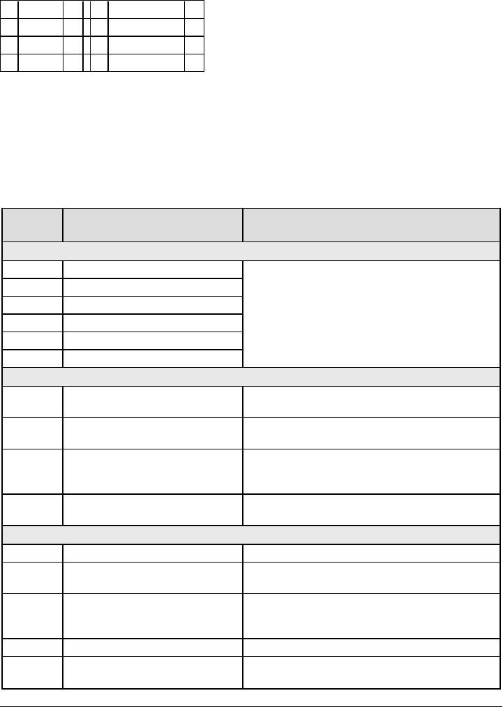
[971] - EEPROM Map Version
[972] - Virtual Keypad Language Version
[976] - Radio Configuration File Version
[977] - Cellular Network Provider - MCC/MNC Code
[978] - Cellular Network Type
00 GPRS 2G 04 LTE 4G
01 EDGE 2G 05 LTE Advanced 4G
02 WCDMA 3G 06 CDMA 2G
03 HSDPA 3G 07 EVDO 3G
[979] - Cellular Network CSQ
[980] - Radio Reset Codes
[981] - Radio Type
[982] - Radio Firmware Version
[983] - Firmware Update Diagnostics Section
Firmware updates for panel and the communicator itself can be made from the communicator.
Table 14: Response Code Descriptions and Corresponding Actions
Response
Code Description of Response Code Corresponding Action
Bad File
00 Version check failed
Contact DSC Tech Support, described the action
attempted with the system and supply them with the
Response Code in Section [983].
01 Image type mismatch
02 Device type mismatch
03 Hardware type mismatch
04 General variant mismatch
05 Firmware header wrong length
Panel is Busy
20 Systemupdate pending - panel is
armed
Disarm the panel to continue with system firmware
update process.
21 System update pending -AC trouble
(Any AC trouble; device/module)
Resolve the AC trouble to continue with system
firmware update process.
22
System update pending -low battery
(Any low battery trouble;
device/module)
Resolve the low battery trouble to continue with
system firmware update process.
25 System update pending -
communication in progress
Retry in a few minutes; if issue persists, contact DSC
Tech Support.
Firmware Update Sequence Change
A0 System firmware update successful None
A1 System firmware update failure At least one module was not updated. Use DLS to
reapply the firmware to the module not updated.
A2 System firmware update failure -
module not found
At least one module was not responding during
firmware update. Ensure all modules enrolled are
physically connected and powered up.
AA Device firmware transfer begin None
AB Device firmware module update
begin None
39
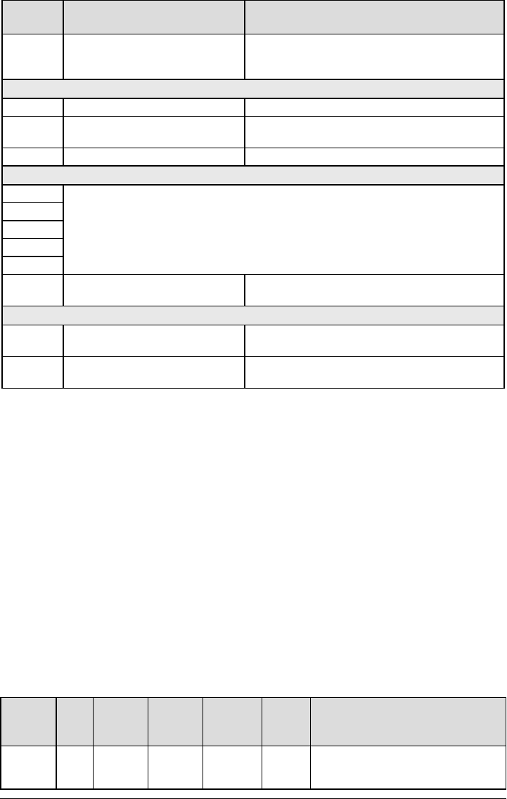
Response
Code Description of Response Code Corresponding Action
AC General device firmware transfer
failure
Contact DSC Tech Support, describe the action
attempted with the system and supply them with the
Response Code in Section [983].
Firmware Update Status
C0 System ready to update. None
C1 System update cancel request
received
The system has received an update cancel request
from DLS.
C2 System update begin None
Firmware Download Request Reject
E0
Reserved
E1
E2
E3
E4
E5 Remote firmware update disabled Enable remote firmware update in the communicator
in order to perform remote system firmware update.
Local Status Update States
FE Firmware file empty No action required. Communicator currently does not
have any firmware files.
FD Firmware download in progress No action required. Communicator is currently
downloading firmware.
The table above displays firmware update indicator codes and meaning of each code. The updates can
be made from communicator. The communicator can update firmware of the panel and also of the com-
municator itself. This section does not provide specific details such as if the image is still stored or erased
due to the cancellation code.
[984] Communicator Status
The communicator status sections provide the installer with the status of the communicator’s func-
tionality, operational readiness, and failures.
The communicator status is displayed as a 6-digit hexadecimal code. The code ranges between 00000F
and 2220CF, though not all numbers in this range are assigned. Each of the 6 digits represents a status
or trouble indicator as below:
1. Digits 1 and 2: Signal strength indicators display the presence/strength of cellular radio.
2. Digit 3: Network Indicator, indicates the operational status of the network.
3. Digits 4 and 5: Trouble Indicator displays the type of issue on the communicator or modules asso-
ciated with and connected to the communicator. See Table 8 for a listing of possible values.
4. Digit 6: Reserved, displays as ‘F’ or ‘-’.
For example, a value of 11002F means:
11- Signal strength is excellent
0 - No network issues
02 - Panel supervision trouble with the communicator
The status code for the radio signal strength, its typical troubles, possible causes and troubleshooting
instructions is displayed in the following table.
Table 15: Radio Signal Strength - Digits 1 and 2
Signal
Strength
CSQ
Level
Signal
Indicator
1
Signal
Indicator
2
Signal
Level
[dBm]
Signal
Level
Status
Action Required
No Signal 0 0 0 -108.8 bad
Check all antenna connections.
Confirm cellular service is active in
area.
40
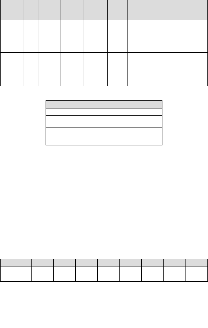
Signal
Strength
CSQ
Level
Signal
Indicator
1
Signal
Indicator
2
Signal
Level
[dBm]
Signal
Level
Status
Action Required
Relocate panel or install external
antenna.
1 Bar 1 - 4 0 2 -108 ~ -
103 weak Relocate panel or install external
antenna if yellow trouble LED has 5
flashes.
2 Bars 5 - 6 0 1 -102 ~ --99 weak
3 Bars 7 - 10 2 1 -98 ~ -91 strong
Location is OK. Cellular signal
strength is greater than CSQ 7.
4 Bars 11 -
13 2 1 -90 ~ -85 strong
5 Bars 14 + 1 1 -84 and
higher excellent
Table 16: Network Indicator - Digit 3
Network Indicator Value Means
OFF No network trouble
ON Ethernet cable disconnected
Ethernet DHCP failed
Flashing
Incoming transmission
Outgoing transmission
Incoming transmission
[985] Radio Initialization Status
The radio initialization status provides installers with the status of radio communication. It is displayed as
an 8-digit toggle option, with each digit indicating a task in the initialization process.
1. Radio power up
2. Received the SMS from C24 Communications
3. Radio reset
4. Radio attached to network
5. Receiver 1 initialized
6. Receiver 2 initialized
7. Receiver 3 initialized
8. Receiver 4 initialized
For example, the radio initialization status code 12-45--- indicates that radio has been powered up, it has
received SMS signal from C24 Communications, the radio is attached to the network, and receiver 1 has
been initialized. This code would update to 12-45678 when receivers 2, 3, and 4 are initialized.
If the radio initialization status code does not indicate any problems, proceed with installation as per this
manual. If troubles are reported, reset the initialization process. If this action does not fix the problem,
refer to the trouble shooting section in this manual.
The following table shows each digit position in the status code, each digit’s value and its assigned mean-
ing in the eight-digit code:
Table 17: Radio Initialization Status - 1-8 bits completion
Bit 1 2 3 4 5 6 7 8
Not Completed - - - - - - - -
Completed 1 2 3 4 5 6 7 8
[987] Language Version
This section will display the current language version of the communicator.
[988] DNS 1 IP Address
This section will display the IP address of DNS Server 1. This is useful when the unit is configured for
DHCP and the IP address assigned to the device by the DHCP Server is needed. This value is pro-
grammed in Section [007] or assigned by DHCP.
41

[989] DNS 2 IP Address
This section will display the IP address of DNS Server 2. This is useful when the unit is configured for
DHCP and the IP address assigned to the device by the DHCP Server is needed. This value is pro-
grammed in section [008] or assigned by DHCP.
[990] Boot Loader Version
This section will display the current boot loader version of the communicator.
[991] Communicator Firmware Version
This section will display the current firmware version of the device. Update worksheets with new version
after a flash update is completed.
[992] Ethernet IP Address
This section will display the IP address of the Ethernet connection. This value is programmed in section
[001] or assigned by DHCP.
[993] Ethernet Gateway Address
This section will display the IP address of the Ethernet gateway. This value is programmed in section
[003] or assigned by DHCP.
[994] Cellular IP Address
This section will display the current dynamic IP address assigned by DHCP to the cellular connection.
NOTE: Cellular uses DHCP (dynamic IP) only. The cellular IP address is always provided by the cellular
network (i.e., not programmable).
[995] SIM Number
This section will display the Subscriber Identity Module (SIM) number of the SIM card installed in the com-
municator. Format is: Major Industry Identifier (2 digits); Mobile Country Code (2 or 3 digits); Mobile Net-
work Code (2 - 3 digits); Unique Number (10 - 12 digits); and Checksum (1 digit). Valid SIM numbers
range is: 18 - 21 numbers. This number is printed on the SIM and the outside of the communicator car-
ton.
NOTE: The checksum digit is omitted on 19-digit SIM card numbers.
[996] Cellular Telephone Number
NOTE: This section will display the cellular telephone number of the SIM. This telephone number is
required by the Installer for DLS and remote firmware (flash) update. User can access this tele-
phone number by entering [*] [6] < > “Cellular Phone No.” to display the phone number.
[997] IMEI Number
This section will display the unique 15-digit International Mobile Equipment Identity (IMEI) of the radio.
Format is: Reporting Body Identifier (2 digits), Allocation Number (4 digits); Final Assembly Code (2
digits); Serial Number (6 digits); and a check digit.
[998] MAC Address
This section will display the unique12-digit, hexadecimal number assigned as the Media Access Control
(MAC) address of the device.
System Reset Defaults
[999] Software Default
Default (99);
The software default allows the installer to refresh the unit after changes and also returns the com-
municator to the default state.
00: Default Module. All programming sections in the module revert to factory settings. This will erase all
existing programming of the unit.
55: Reset. The communicator is reset. This option is equivalent to power cycling the communicator.
42
Ethernet Cellular Programming
Worksheets
System Options
[001] Ethernet IP Address
Default (000.000.000.000)
[002] Ethernet IP Subnet Mask
Default (255.255.255.000)
[003] Ethernet Gateway IP Address
Default (000.000.000.000)
[004] Receiver Supervision Interval
Default (0087/135) Valid range: 0000 - FFFF.
[005] System Toggle Options
[1] Ethernet Receiver 1 Supervised (OFF).
[2] Cellular Receiver 1 Supervised (OFF).
[3] Supervision Type (OFF).
[4] Primary Communications Path.
[OFF] TL2803G(R)E; TL280LE(R)
[ON] 3G2080(R)E; LE2080(R).
[5] Redundant Communications (OFF).
[6] Remote Firmware Upgrade (ON).
[7] Alternate Test Transmission (OFF).
[8] Cellular Low Signal Trouble (OFF).
[006] System Toggle Options 2
[1] Ethernet Receiver 1 Enabled (ON).
[2] Ethernet Receiver 2 Enabled (ON).
[4] Cellular Receiver 1 Enabled (ON).
[5] Cellular Receiver 2 Enabled (ON).
[7] DLS Over Cellular (ON).
[8] Network Trouble Suppression (OFF).
[007] DNS Server IP 1
Default (000.000.000.000)
[008] DNS Server IP 2
Default (000.000.000.000)
[009] Language
Default (01); Program label language 01-29
OPT Language OPT Language OPT Language
01 English 11 Swedish 21 Russian
OPT Language OPT Language OPT Language
02 Spanish 12 Norwegian 22 Bulgarian
03 Portuguese 13 Danish 23 Latvian
04 French 14 Hebrew 24 Lithuanian
05 Italian 15 Greek 25 Ukrainian
06 Dutch 16 Turkish 26 Slovakian
07 Polish 17 Chinese 27 Serbian
08 Czech 18 Croatian 28 Estonian
09 Finnish 19 Hungarian 29 Slovenian
10 German 20 Romanian 30-99 Reserved
Programming Options
[010] System Toggle Options 3
[1] 2-Way Audio Over Cellular (OFF)
[2] Visual Verification Default (OFF).
[3] Video On Demand (OFF)
[011] Installer Code
Default (CAFE) Valid range: 0000 - FFFF.
[012] DLS Incoming Port
Default (0BF6/3062) Valid range: 0000 - FFFF.
[013] DLS Outgoing Port
Default (0BFA/3066) Valid range: 0000 - FFFF.
[015] DLS Call-Up IP
Default (000.000.000.000)
[016] DLS Call-Up Port
Default (0000) Valid range: 0000 - FFFF.
[020] Time Zone
Default (00) Valid range: 00 - 99.
[021] Account Code
Default (FFFFFF) Valid range: 000001 - FFFFFE.
[022] Communications Format
Default (04) Program 03 (CID), 04 (SIA).
[023] Panel Absent Trouble
Default (FF); Program 00 disable or FF enable.
[024] Panel Absent Trouble Restore
Default (FF) Program 00 disable or FF enable.
[025] Radio Activation Restore
Default (FF) Program 00 disable or FF enable.
43

System Test Options
[026] Ethernet 1 Test Transmission
Default (FF) Program 00 disable or FF enable.
[027] Ethernet 2 Test Transmission
Default (00) Program 00 disable or FF enable.
[028] Cellular 1 Test Transmission
Default (FF) Program 00 disable or FF enable.
[029] Cellular 2 Test Transmission
Default (00) Program 00 disable or FF enable.
[030] FTC Restore
Default (FF) Program 00 disable or FF enable.
[033] Communicator Firmware Update Begin
Default (FF) Program 00 disable or FF enable.
[034] Communicator Firmware Update Success
Default (FF) Program 00 disable or FF enable.
[095] SA Incoming Local Port
Default (0C14/3092) Valid range: 0000 - FFFF.
[096] SA Outgoing Local Port
Default (0C15/3093) Valid range: 0000 - FFFF.
[097] SA User Call Up IP
Default (000.000.000.000)
[098] SA User Call Up Port
Default (0000) Valid range: 0000 - FFFF.
[099] SA Password
Default (FFFFFFFF) Valid range: 00000000 -
FFFFFFFF.
Ethernet Receiver 1 Options
[101] Ethernet Receiver 1 Account Code
Default (0000000000)
Valid range: 0000000001 - FFFFFFFFFE.
[102] Ethernet Receiver 1 DNIS
Default (000000) Valid range: 000000 - FFFFFF.
[103] Ethernet Receiver 1 Address
Default (127.000.000.001)
[104] Ethernet Receiver 1 UDP Remote Port
Default (0BF5/3061) Valid range: 0000 - FFFF.
[105] Ethernet Receiver 1 UDP Local Port
Default (0BF4/3060)Valid range: 0000 - FFFF.
[106] Ethernet Receiver 1 Domain Name
Default ( ) 32 ASCII characters.
________________________________
Ethernet Receiver 2 Options
[111] Ethernet Receiver 2 Account Code
Default (0000000000)
Valid range: 0000000001 - FFFFFFFFFE.
[112] Ethernet Receiver 2 DNIS
Default (000000) Valid range: 000000 - 0FFFFF.
[113] Ethernet Receiver 2 Address
Default (000.000.000.000)
[114] Ethernet Receiver 2 UDP Remote Port
Default (0BF5/3061) Valid range: 0000 - FFFF.
[115] Ethernet Receiver 2 UDP Local Port
Default (0BF9/3065) Valid range: 0000 -FFFF.
[116] Ethernet Receiver 2 Domain Name
Default ( ) 32 ASCII characters.
____________________________________
Ethernet Options
[124] Ethernet Test Transmission Time
Default (9999) Valid: 00-23(HH); 00-59(MM)
[125] Ethernet Test Transmission Cycle
Default (000000)
Valid range: 000000 - 999999 minutes.
Cellular Receiver 1 Options
[201] Cellular Receiver 1 Account Code
Default (0000000000)
Valid range: 0000000001 - FFFFFFFFFE.
[202] Cellular Receiver 1 DNIS
Default (000000) Valid range: 000000 - 0FFFFF.
[203] Cellular Receiver 1 Address
Default (000.000.000.000)
44

[204] Cellular Receiver 1 Port
Default (0BF5/3061) Valid range: 0000 - FFFF.
[205] Cellular Receiver 1 APN
32 ASCII characters.
____________________________________
[206] Cellular Receiver 1 Domain Name
32 ASCII characters.
____________________________________
Cellular Receiver 2 Options
[211] Cellular Receiver 2 Account Code
Default (0000000000)
Valid range: 0000000001 - FFFFFFFFFE.
[212] Cellular Receiver 2 DNIS
Default (000000)
Valid range: 000000 - 0FFFFF.
[213] Cellular Receiver 2 Address
Default (000.000.000.000)
[214] Cellular Receiver 2 Port
Default (0BF5/3061) Valid range: 0000 - FFFF.
[215] Cellular Receiver 2 APN
Default ( ) 32 ASCII characters.
____________________________________
[216] Cellular Receiver 2 Domain Name
Default ( ) 32 ASCII characters.
____________________________________
Cellular Options
[221] Cellular Public Access Point Name
Default ( ) 32 ASCII characters
____________________________________
[222] Cellular Login User Name
Default ( ) 32 ASCII characters.
____________________________________
[223] Cellular Login Password
Default ( ) 32 ASCII characters.
____________________________________
[224] Cellular Test Transmission Time of Day
Default (9999) Valid range: 00 - 23 hrs. (HH) 00 -
59 min. (MM).
[225] Cellular Test Transmission Cycle
Default (000000)
Valid range: 000000 - 999999 minutes.
[226] Network Trouble Delay
Default (0F)
Valid entries from, 00 to FF.
[227] Voice Call Timeout
Default (00)
Valid entries from, 00 to FF.
[228] Voice Call Back Time
Default (0A)
Valid entries from, 00 to FF.
[229] Voice Call Back Number
________________________________
Command and Control Options
[301] Command and Control Toggle Options
[1] SMS Notification (ON).
[2] Serial Communication Port enabled (OFF)
[3] SMS Command and Control Default (ON).
[4] Interactive (OFF)
[5] SMS Character Format (OFF)
[6] Long SMS Message Handling Default
(OFF).
[7] Reserved
[8] Reserved
[307] SMSDelimiter
Default ()
Valid entries from, 00 to FF.
[308] Outgoing SMS Retry Attempts
Default (19)
Valid entries from, 00 to FF.
[309] Outgoing SMS Retry Counter
Default (000F) Valid range: 0000 - FFFF.
[311]-[342] SMS Phone Number 1-32
_______________________________________
_______
[343]-[374] SMS Phone Number 1-32 Toggle
Options
[1] SMS Notification Alarm/Restore Default
(ON).
[2] SMS Notification Tamper/Restore Default
(ON)
[3] SMS Notification Opening/Closing Default
(ON)
[4] SMS Notification System Maintenance
45

Default (ON)
[5] SMS Notification System Test Default (ON)
[6] SMS Notification Internal Events Default
(ON).
[7] SMS Notification Enabled Default (ON).
[8] SMS Command and Control Enabled
Default (ON).
[375]-[406] SMS Phone Number 1-32 Partition
Assignment
Default (00) Valid range: 00 - FF.
00 - Global; 01-32 - Partition; FF - Disabled
[420] Serial Port Baud Rate ('R' models only)
Default (05)
01=9600 Baud; 02=19200 Baud; 03=38400 Baud;
04=57600 Baud; 05=115200 Baud
[421] Serial Port Settings ('R' models only)
[1] Parity Enabled (OFF)
[2] Parity Type (OFF-Even Parity)
[3] 2 Stop Bit s (OFF-1 Stop Bit)
[4] Flow Control (OFF)
[422] Integration Identification Number
Default (MAC/IMEI)
[423] Session 1 Integration Access Code
Default (12345678) Valid range: 00000000 -
FFFFFFFF
[424] Session 1 SMS Label
Default (11111111)
_______________________________________
_______
[425] Session 1 Integration Toggle Options 2
[1] Integration Over Serial Port (ON)
[2] Integration Over Cellular (OFF)
[3] Integration Over Ethernet (OFF)
[4] Reserved
[5] Integration Protocol (ON)
[6] Interactive Protocol SMA (OFF)
[7] Reserved
[8] Interactive Encryption for SMA (ON)
[426] Session 1 Integration Toggle Options 3
[1] UDP Polling (OFF)
[2] TCP Polling (OFF)
[3] Real-time Notification (OFF)
[4] Notification Follows Pool (OFF)
[5] Reserved
[6] Reserved
[7] Reserved
[8] Reserved
[427] Session 1 Interactive Polling Interval
Default (000A) Valid range: 0000 - FFFF seconds.
[428] Session 1 Integration Server IP
Default (000.000.000.000)
[429] Session 1 Integration Notification Port
Default (0C00/00372) Valid range: 0000 - FFFF.
[430] Session 1 Integration Polling Port
Default (0C01/3073) Valid range: 0000 - FFFF.
[431] Session 1 Integration Server DNS
32 ASCII characters.
____________________________________
[432] Session 1 Integration Outgoing Port
Default (0C04/3076) Valid range: 0000 - FFFF.
[433] Session 1 Integration Incoming Port
Default (0BFF/3071) Valid range: 0000 - FFFF.
[434] Session 1 Notification Zone 1-8 Toggle
[1] Zone 1 Default (ON)
[2] Zone 2 Default (ON)
[3] Zone 3 Default (ON)
[4] Zone 4 Default (ON)
[5] Zone 5 Default (ON)
[6] Zone 6 Default (ON)
[7] Zone 7 Default (ON)
[8] Zone 8 Default (ON)
[435] Session 1 Notification Zone 9-16 Toggle
[1] Zone 9 Default (ON)
[2] Zone 10 Default (ON)
[3] Zone 11 Default (ON)
[4] Zone 12 Default (ON)
[5] Zone 13 Default (ON)
[6] Zone 14 Default (ON)
[7] Zone 15 Default (ON)
[8] Zone 16 Default (ON)
[436] Session 1 Notification Zone 17-24 Toggle
[1] Zone 17 Default (ON)
[2] Zone 18 Default (ON)
[3] Zone 19 Default (ON)
46

[4] Zone 20 Default (ON)
[5] Zone 21 Default (ON)
[6] Zone 22 Default (ON)
[7] Zone 23 Default (ON)
[8] Zone 24 Default (ON)
[437] Session 1 Notification Zone 25-32 Toggle
[1] Zone 25 Default (ON)
[2] Zone 26 Default (ON)
[3] Zone 27 Default (ON)
[4] Zone 28 Default (ON)
[5] Zone 29 Default (ON)
[6] Zone 30 Default (ON)
[7] Zone 31 Default (ON)
[8] Zone 32 Default (ON)
[438] Session 1 Notification Zone 33-40 Toggle
[1] Zone 33 Default (ON)
[2] Zone 34 Default (ON)
[3] Zone 35 Default (ON)
[4] Zone 36 Default (ON)
[5] Zone 37 Default (ON)
[6] Zone 38 Default (ON)
[7] Zone 39 Default (ON)
[8] Zone 40 Default (ON)
[439] Session 1 Notification Zone 41-48 Toggle
[1] Zone 41 Default (ON)
[2] Zone 42 Default (ON)
[3] Zone 43 Default (ON)
[4] Zone 44 Default (ON)
[5] Zone 45 Default (ON)
[6] Zone 46 Default (ON)
[7] Zone 47 Default (ON)
[8] Zone 48 Default (ON)
[440] Session 1 Notification Zone 49-56 Toggle
[1] Zone 49 Default (ON)
[2] Zone 50 Default (ON)
[3] Zone 51 Default (ON)
[4] Zone 52 Default (ON)
[5] Zone 53 Default (ON)
[6] Zone 54 Default (ON)
[7] Zone 55 Default (ON)
[8] Zone 56 Default (ON)
[441] Session 1 Notification Zone 57-64 Toggle
[1] Zone 57 Default (ON)
[2] Zone 58 Default (ON)
[3] Zone 59 Default (ON)
[4] Zone 60 Default (ON)
[5] Zone 61 Default (ON)
[6] Zone 62 Default (ON)
[7] Zone 63 Default (ON)
[8] Zone 64 Default (ON)
[442] Session 1 Notification Zone 65-72 Toggle
[1] Zone 65 Default (ON)
[2] Zone 66 Default (ON)
[3] Zone 67 Default (ON)
[4] Zone 68 Default (ON)
[5] Zone 69 Default (ON)
[6] Zone 70 Default (ON)
[7] Zone 71 Default (ON)
[8] Zone 72 Default (ON)
[443] Session 1 Notification Zone 73-80 Toggle
[1] Zone 73 Default (ON)
[2] Zone 74 Default (ON)
[3] Zone 75 Default (ON)
[4] Zone 76 Default (ON)
[5] Zone 77 Default (ON)
[6] Zone 78 Default (ON)
[7] Zone 79 Default (ON)
[8] Zone 80 Default (ON)
[444] Session 1 Notification Zone 81-88 Toggle
[1] Zone 81 Default (ON)
[2] Zone 82 Default (ON)
[3] Zone 83 Default (ON)
[4] Zone 84 Default (ON)
[5] Zone 85 Default (ON)
[6] Zone 86 Default (ON)
[7] Zone 87 Default (ON)
[8] Zone 88 Default (ON)
[445] Session 1 Notification Zone 89-96 Toggle
[1] Zone 89 Default (ON)
[2] Zone 90 Default (ON)
[3] Zone 91 Default (ON)
[4] Zone 92 Default (ON)
[5] Zone 93 Default (ON)
[6] Zone 94 Default (ON)
[7] Zone 95 Default (ON)
[8] Zone 96 Default (ON)
[446] Session 1 Notification Zone 97-104 Toggle
[1] Zone 97 Default (ON)
47

[2] Zone 98 Default (ON)
[3] Zone 99 Default (ON)
[4] Zone 100 Default (ON)
[5] Zone 101 Default (ON)
[6] Zone 102 Default (ON)
[7] Zone 103 Default (ON)
[8] Zone 104 Default (ON)
[447] Session 1 Notification Zone 105-112 Toggle
[1] Zone 105 Default (ON)
[2] Zone 106 Default (ON)
[3] Zone 107 Default (ON)
[4] Zone 108 Default (ON)
[5] Zone 109 Default (ON)
[6] Zone 110 Default (ON)
[7] Zone 111 Default (ON)
[8] Zone 112 Default (ON)
[448] Session 1 Notification Zone 113-120 Toggle
[1] Zone 113 Default (ON)
[2] Zone 114 Default (ON)
[3] Zone 115 Default (ON)
[4] Zone 116 Default (ON)
[5] Zone 117 Default (ON)
[6] Zone 118 Default (ON)
[7] Zone 119 Default (ON)
[8] Zone 120 Default (ON)
[449] Session 1 Notification Zone 121-128 Toggle
[1] Zone 121 Default (ON)
[2] Zone 122 Default (ON)
[3] Zone 123 Default (ON)
[4] Zone 124 Default (ON)
[5] Zone 125 Default (ON)
[6] Zone 126 Default (ON)
[7] Zone 127 Default (ON)
[8] Zone 128 Default (ON)
[450]-[476] Repeats [423]-[449] for Session 2
[477]-[503] Repeats [423]-[449] for Session 3
[504]-[530] Repeats [423]-[449] for Session 4
[691] Session 1 Notification Control
[1] Alarm and Alarm Restore Notifications
[2] Tamper and Tamper Restore Notifications
[3] Disarming Notifications
[4] Arming Notifications
[5] Trouble and Trouble Restore Notifications
[6] Test Transmission Notifications
[7] Lighting Notifications (Neo 1.4+ only)
[8] Temperature Notifications (Neo 1.4+ only)
[692] Session 2 Notification Control
[1] Alarm and Alarm Restore Notifications
[2] Tamper and Tamper Restore Notifications
[3] Disarming Notifications
[4] Arming Notifications
[5] Trouble and Trouble Restore Notifications
[6] Test Transmission Notifications
[7] Lighting Notifications (Neo 1.4+ only)
[8] Temperature Notifications (Neo 1.4+ only)
[693] Session 3 Notification Control
[1] Alarm and Alarm Restore Notifications
[2] Tamper and Tamper Restore Notifications
[3] Disarming Notifications
[4] Arming Notifications
[5] Trouble and Trouble Restore Notifications
[6] Test Transmission Notifications
[7] Lighting Notifications (Neo 1.4+ only)
[8] Temperature Notifications (Neo 1.4+ only)
[694] Session 4 Notification Control
[1] Alarm and Alarm Restore Notifications
[2] Tamper and Tamper Restore Notifications
[3] Disarming Notifications
[4] Arming Notifications
[5] Trouble and Trouble Restore Notifications
[6] Test Transmission Notifications
[7] Lighting Notifications (Neo 1.4+ only)
[8] Temperature Notifications (Neo 1.4+ only)
[708] Event Report Retry Interval
Default (0A14285000000000)
Valid range: 0000000000000000 -
FFFFFFFFFFFFFFFF.
[709] Event Report Retry Timeout
Default (0000012C) Valid range: 00000000 -
FFFFFFFF.
[710] Lifestyle Event Log Sync Timeout
Default (00015180) Valid range: 00000000 -
FFFFFFFF.
[711] Integration Inactivity Timeout
Default (00000078) Valid range: 00000000 -
FFFFFFFF.
48

[716] Lifestyle Reset Window
Default (0E10) Valid range: 0000 - FFFF.
[720] Local debug TCP Port
Default (0000) Valid range: 0000 - FFFF.
[722] Lifestyle Zone 1-8 Toggle
[1] Zone 1 Default (ON)
[2] Zone 2 Default (ON)
[3] Zone 3 Default (ON)
[4] Zone 4 Default (ON)
[5] Zone 5 Default (ON)
[6] Zone 6 Default (ON)
[7] Zone 7 Default (ON)
[8] Zone 8 Default (ON)
[723] Lifestyle Zone 9-16 Toggle
[1] Zone 9 Default (ON)
[2] Zone 10 Default (ON)
[3] Zone 11 Default (ON)
[4] Zone 12 Default (ON)
[5] Zone 13 Default (ON)
[6] Zone 14 Default (ON)
[7] Zone 15 Default (ON)
[8] Zone 16 Default (ON)
[724] Lifestyle Zone 17-24 Toggle
[1] Zone 17 Default (ON)
[2] Zone 18 Default (ON)
[3] Zone 19 Default (ON)
[4] Zone 20 Default (ON)
[5] Zone 21 Default (ON)
[6] Zone 22 Default (ON)
[7] Zone 23 Default (ON)
[8] Zone 24 Default (ON)
[725] Lifestyle Zone 25-32 Toggle
[1] Zone 25 Default (ON)
[2] Zone 26 Default (ON)
[3] Zone 27 Default (ON)
[4] Zone 28 Default (ON)
[5] Zone 29 Default (ON)
[6] Zone 30 Default (ON)
[7] Zone 31 Default (ON)
[8] Zone 32 Default (ON)
[726] Lifestyle Zone 33-40 Toggle
[1] Zone 33 Default (ON)
[2] Zone 34 Default (ON)
[3] Zone 35 Default (ON)
[4] Zone 36 Default (ON)
[5] Zone 37 Default (ON)
[6] Zone 38 Default (ON)
[7] Zone 39 Default (ON)
[8] Zone 40 Default (ON)
[727] Lifestyle Zone 41-48 Toggle
[1] Zone 41 Default (ON) Default (ON)
[2] Zone 42 Default (ON)
[3] Zone 43 Default (ON)
[4] Zone 44 Default (ON)
[5] Zone 45 Default (ON)
[6] Zone 46 Default (ON)
[7] Zone 47 Default (ON)
[8] Zone 48 Default (ON)
[728] Lifestyle Zone 49-56 Toggle
[1] Zone 49 Default (ON)
[2] Zone 50 Default (ON)
[3] Zone 51 Default (ON)
[4] Zone 52 Default (ON)
[5] Zone 53 Default (ON)
[6] Zone 54 Default (ON)
[7] Zone 55 Default (ON)
[8] Zone 56 Default (ON)
[729] Lifestyle Zone 57-64 Toggle
[1] Zone 57 Default (ON)
[2] Zone 58 Default (ON)
[3] Zone 59 Default (ON)
[4] Zone 60 Default (ON)
[5] Zone 61 Default (ON)
[6] Zone 62 Default (ON)
[7] Zone 63 Default (ON)
[8] Zone 64 Default (ON)
[730] Lifestyle Zone 65-72 Toggle
[1] Zone 65 Default (ON)
[2] Zone 66 Default (ON)
[3] Zone 67 Default (ON)
[4] Zone 68 Default (ON)
[5] Zone 69 Default (ON)
[6] Zone 70 Default (ON)
[7] Zone 71 Default (ON)
[8] Zone 72 Default (ON)
[731] Lifestyle Zone 73-80 Toggle
[1] Zone 73 Default (ON)
49

[2] Zone 74 Default (ON)
[3] Zone 75 Default (ON)
[4] Zone 76 Default (ON)
[5] Zone 77 Default (ON)
[6] Zone 78 Default (ON)
[7] Zone 79 Default (ON)
[8] Zone 80 Default (ON)
[732] Lifestyle Zone 81-88 Toggle
[1] Zone 81 Default (ON)
[2] Zone 82 Default (ON)
[3] Zone 83 Default (ON)
[4] Zone 84 Default (ON)
[5] Zone 85 Default (ON)
[6] Zone 86 Default (ON)
[7] Zone 87 Default (ON)
[8] Zone 88 Default (ON)
[733] Lifestyle Zone 89-96 Toggle
[1] Zone 89 Default (ON)
[2] Zone 90 Default (ON)
[3] Zone 91 Default (ON)
[4] Zone 92 Default (ON)
[5] Zone 93 Default (ON)
[6] Zone 94 Default (ON)
[7] Zone 95 Default (ON)
[8] Zone 96 Default (ON)
[734] Lifestyle Zone 97-104 Toggle
[1] Zone 97 Default (ON)
[2] Zone 98 Default (ON)
[3] Zone 99 Default (ON)
[4] Zone 100 Default (ON)
[5] Zone 101 Default (ON)
[6] Zone 102 Default (ON)
[7] Zone 103 Default (ON)
[8] Zone 104 Default (ON)
[735] Lifestyle Zone 105-112 Toggle
[1] Zone 105 Default (ON)
[2] Zone 106 Default (ON)
[3] Zone 107 Default (ON)
[4] Zone 108 Default (ON)
[5] Zone 109 Default (ON)
[6] Zone 110 Default (ON)
[7] Zone 111 Default (ON)
[8] Zone 112 Default (ON)
[736] Lifestyle Zone 113-120 Toggle
[1] Zone 113 Default (ON)
[2] Zone 114 Default (ON)
[3] Zone 115 Default (ON)
[4] Zone 116 Default (ON)
[5] Zone 117 Default (ON)
[6] Zone 118 Default (ON)
[7] Zone 119 Default (ON)
[8] Zone 120 Default (ON)
[737] Lifestyle Zone 121-128 Toggle
[1] Zone 121 Default (ON)
[2] Zone 122 Default (ON)
[3] Zone 123 Default (ON)
[4] Zone 124 Default (ON)
[5] Zone 125 Default (ON)
[6] Zone 126 Default (ON)
[7] Zone 127 Default (ON)
[8] Zone 128 Default (ON)
External Event Label Programming
[738] Burglary Alarm
Default (Burglary Alarm)
______________________________________
[739] Burglary Alarm Restore
Default (Burglary Alarm Restore)
______________________________________
[740] Fire Alarm
Default (Fire Alarm)
______________________________________
[741] Fire Alarm Restore
Default (Fire Alarm Restore)
______________________________________
[742] 24 Hour Alarm
Default (24 Hour Alarm)
______________________________________
[743] 24 Hour Alarm Restore
Default (24 Hour Alarm Restore)
______________________________________
[744] Holdup Alarm
Default (Holdup Alarm)
______________________________________
[745] Holdup Alarm Restore
Default (Holdup Alarm Restore)
______________________________________
[746] Gas Alarm
Default (Gas Alarm)
______________________________________
[747] Gas Alarm Restore
Default (Gas Alarm Restore)
______________________________________
50

[748] High Temperature Alarm
Default (High Temperature Alarm)
_______________________________________
[749] High Temperature Alarm Restore
Default (High Temperature Alarm Restore)
_______________________________________
[750] Medical Alarm
Default (Medical Alarm)
______________________________________
[751] Medical Alarm Restore
Default (Medical Alarm Restore)
______________________________________
[752] Panic Alarm
Default (Panic Alarm)
______________________________________
[753] Panic Alarm Restore
Default (Panic Alarm Restore)
______________________________________
[754] Emergency Alarm
Default (Emergency Alarm)
_______________________________________
[755] Emergency Alarm Restore
Default (Emergency Alarm Restore)
______________________________________
[756] Sprinkler Alarm
Default (Sprinkler Alarm)
_______________________________________
[757] Sprinkler Alarm Restore
Default (Sprinkler Alarm Restore)
_______________________________________
[758] Water Level Alarm
Default (Water Level Alarm)
_______________________________________
[759] Water Level Alarm Restore
Default (Water Level Alarm Restore)
_______________________________________
[760] Low Temperature Alarm
Default (Low Temperature Alarm)
_______________________________________
[761] Low Temperature Alarm Restore
Default (Low Temperature Alarm Restore)
_______________________________________
[762] Fire Supervisory
Default (Fire Supervisory)
_______________________________________
[763] Fire Supervisory Restore
Default (Fire Supervisory Restore)
_______________________________________
[764] CO Alarm
Default (CO Alarm)
_______________________________________
[765] CO Alarm Restore
Default (CO Alarm Restore)
_______________________________________
[766] Water Alarm
Default (Flood Alarm)
_______________________________________
[767] Water Alarm Restore
Default (Flood Alarm Restore)
_______________________________________
[768] Quick Bypass Alarm
Default (Quick Bypass Alarm)
_______________________________________
[769] Quick Bypass Alarm Restore
Default (Quick Bypass Alarm Restore)
_______________________________________
[770] Aux Alarm
Default (Aux Alarm)
_______________________________________
[771] Aux Alarm Restore
Default (Aux Alarm Restore)
_______________________________________
[772] Zone Expander Supervisory Alarm
Default (Zone Expander Supervisory Alarm)
_______________________________________
[773] Zone Expander Sup. Alarm Restore
Default (Zone Expander Sup. Alarm Restore)
_______________________________________
[774] Duress Alarm
Default (Duress Alarm)
_______________________________________
[775] Account Label
Default (Security System)
_______________________________________
[776] General System Tamper
Default (General System Tamper)
_______________________________________
[777] General System Tamper Restore
Default (General System Tamper Restore)
_______________________________________
[778] General System Trouble
Default (General System Trouble)
_______________________________________
[779] General System Restore
Default (General System Restore)
_______________________________________
[780] Panel AC Power Trouble Label
Default (AC Power Trouble)
_______________________________________
[781] Panel AC Power Restore Label
Default (AC Power Restore)
_______________________________________
[782] Panel Auxiliary Power Trouble
Default (Auxiliary Power Trouble)
______________________________________
51

[783] Panel Auxiliary Power Restore
Default (Auxiliary Power Restore)
_______________________________________
[784] Panel Battery Trouble
Default (Battery Trouble)
_______________________________________
[785] Panel Battery Restore
Default (Battery Trouble Restore)
_______________________________________
[786] Panel Bell Circuit Trouble
Default (Bell Circuit Trouble)
_______________________________________
[787] Panel Bell Circuit Restore
Default (Bell Circuit Restore)
_______________________________________
[788] Panel Telephone Line Trouble
Default (Telephone Line Failure)
_______________________________________
[789] Panel Telephone Line Restore
Default (Telephone Line Restore)
_______________________________________
[790] Fail to Communicate Trouble
Default (Fail to Communicate Trouble)
_______________________________________
[791] Fail to Communicate Restore
Default (Fail to Communicate Restore)
_______________________________________
[792] Fire Trouble
Default (Fire Trouble)
_______________________________________
[793] Fire Trouble Restore
Default (Fire Trouble Restore)
_______________________________________
[794] Zone Tamper
Default (Zone Tamper)
_______________________________________
795] Zone Tamper Restore
Default (Zone Tamper Restore)
_______________________________________
[796] Zone Fault
Default (Zone Fault)
_______________________________________
[797] Zone Fault Restore
Default (Zone Fault Restore)
_______________________________________
[798] Alternate Communicator Trouble
Default (Alternate Communicator Trouble)
_______________________________________
[799] Alternate Communicator Restore
Default (Alternate Communicator Restore)
_______________________________________
[800] Module Trouble
Default (Module Trouble)
______________________________________
[801] Module Trouble Restore
Default (Module Trouble Restore)
_______________________________________
[802] Wireless/AML Device Trouble
Default (Device Trouble)
_______________________________________
[803] Wireless/AML Device Restore
Default (Device Trouble Restore)
_______________________________________
[804] Disarmed By
Default (Disarmed By)
_______________________________________
[805] Armed By
Default (Armed By)
_______________________________________
[806] Disarmed
Default (Disarmed)
_______________________________________
[807] Armed
Default (Armed)
_______________________________________
[808] Automatic Disarming
Default (Automatic Disarming)
_______________________________________
[809] Automatic Arming
Default (Automatic Arming)
_______________________________________
[810] Automatic Arming Cancelled
Default (Automatic Arming Cancelled)
_______________________________________
[811] Late to Open
Default (Late to Open)
_______________________________________
[812] Late to Close
Default (Late to Close)
_______________________________________
[813] Disarmed After Alarm
Default (Disarmed After Alarm)
_______________________________________
[814] Alarm Ocurred After Arming
Default (Alarm Ocurred After Arming)
_______________________________________
[815] Exit Fault
Default (Exit Fault)
_______________________________________
[816] Cold Start
Default (Cold Start)
_______________________________________
[817] Armed With Zones Bypassed
Default (Armed With Zones Bypassed)
_______________________________________
52

[818] Zone Bypassed
Default (Zone Bypassed)
_______________________________________
[819] Zone Unbypassed
Default (Zone Unbypassed)
_______________________________________
[820] Burglary Verified
Default (Burglary Verified)
_______________________________________
[821] Burglary Not Verified
Default (Burglary Not Verified)
_______________________________________
[822] Alarm Cancelled
Default (Alarm Cancelled)
_______________________________________
[823] Holdup Verified
Default (Holdup Verified)
_______________________________________
[824] Walk Test Begin
Default (Walk Test Begin)
_______________________________________
[825] Walk Test End
Default (Walk Test End)
_______________________________________
[826] System Test
Default (Test Message)
_______________________________________
[827] Periodic Test Transmission
Default (Periodic Test)
_______________________________________
[828] Periodic Test With Trouble
Default (Periodic Test With Trouble)
_______________________________________
[829] DLS Remote Programming Begin
Default (Remote Programming Begin)
_______________________________________
[830] DLS Remote Programming End
Default (Remote Programming End)
_______________________________________
[831] SA Remote Programming Begin
Default (Remote Programming Begin)
_______________________________________
[832] SA Remote Programming End
Default (Remote Programming End)
_______________________________________
[833] Installer Lead In
Default (Local Programming Begin)
_______________________________________
[834] Installer Lead Out
Default (Local Programming End)
_______________________________________
[835] Firmware Update Begin
Default (Firmware Update Begin)
_______________________________________
[836] Firmware Update Successful
Default (Firmware Update Successful)
_______________________________________
[837] Firmware Update Fail
Default (Firmware Update Fail)
_______________________________________
[838] Delinquency
Default (Delinquency)
_______________________________________
[839] Keypad Lockout
Default (Keypad Lockout)
_______________________________________
[840] Event Log 75% full
Default (Event Log Near Full)
_______________________________________
[841] FTC Trouble
Default (fail to communicate trouble)
_______________________________________
[842] FTC Restore
Default (fail to communicate restore)
_______________________________________
[843] Panel Absent Trouble
Default (Panel Communications Trouble)
_______________________________________
[844] Panel Absent Trouble Restore
Default (Panel Communications Restore)
_______________________________________
[845] Module Reprogramming
Default (Communicator Programming Updated)
_______________________________________
[846] Firmware Update
Default (Communicator Programming Updated)
_______________________________________
[850] Module
Default (Module)
_______________________________________
[851] Stay Arm
Default (Stay Arm)
_______________________________________
[852] Away Arm
Default (Away Arm)
_______________________________________
[853] Night Arm
Default (Night Arm)
_______________________________________
[854] Disarm
Default (Disarm)
_______________________________________
[855] Activate Command Output 1
Default (Activate Command Output 1)
_______________________________________
53

[856] Activate Command Output 2
Default (Activate Command Output 2)
_______________________________________
[857] Activate Command Output 3
Default (Activate Command Output 3)
_______________________________________
[858] Activate Command Output 4
Default (Activate Command Output 4)
_______________________________________
[859] Deactivate Command Output 1
Default (Deactivate Command Output 1)
_______________________________________
[860] Deactivate Command Output 2
Default (Deactivate Command Output 2)
_______________________________________
[861] Deactivate Command Output 3
Default (Deactivate Command Output 3)
_______________________________________
[862] Deactivate Command Output 4
Default (Deactivate Command Output 4)
_______________________________________
[863] Bypass
Default (Bypass)
_______________________________________
[864] Unbypass
Default (Unbypass)
_______________________________________
[865] Status Request
Default (Status Request)
_______________________________________
[866] Alarm Memory Request
Default (Alarm Memory Request)
_______________________________________
[867] Help
Default (Help)
_______________________________________
[868] Pay As You Go Balance Request
Default (Balance Request)
_______________________________________
[869] Keypad Message
Default (Keypad Message)
_______________________________________
[870] Function Successful
Default (Successful)
_______________________________________
[871] Function Failure
Default (Unsuccessful)
_______________________________________
[872] Invalid Command
Default (Invalid Command)
_______________________________________
[873] System Stay Armed
Default (Stay Armed)
_______________________________________
[874] System Away Armed
Default (Away Armed)
_______________________________________
[875] System Night Armed
Default (Night Armed)
_______________________________________
[876] System Disarmed Ready
Default (Disarmed Ready)
_______________________________________
[877] System Disarmed, Not Ready
Default (Disarmed Not Ready)
_______________________________________
[878] System In Alarm
Default (is in Alarm)
_______________________________________
[879] Trouble Label
Default (Service is Required)
_______________________________________
[880] No Alarms in Memory
Default (No Alarms in Memory)
_______________________________________
[881] Pay As You Go Balance
Default (Pay as you go balance:)
_______________________________________
[882] Pay As You Go Message
Default (*123#)
_______________________________________
[883] Response Code
Default (Response Code)
_______________________________________
Receiver Diagnostic Testing
[901] Diagnostic Test Transmission
[1] Ethernet 1 Default (OFF).
[2] Ethernet 2 Default (OFF).
[3] Cellular 1 Default (OFF).
[4] Cellular 2 Default (OFF).
[961] Cellular Inactivity Timeout
Default (41)
Valid entries from, 00 to FF.
[962] CREG Max Registration
Default (C8)
Valid entries from, 00 to FF.
[963] Retransmission Delay
Default (2D)
Valid entries from, 00 to FF.
54

[964] Voice Volume
Default (04)
Valid entries from, 00 to FF.
[965] Microphone Gain
Default (01)
Valid entries from, 00 to FF.
[966] SMS Recovery Hour
Default (0018) Valid range: 0000 - FFFF.
[967] SMS Threshold 1
Default (0032) Valid range: 0000 - FFFF.
[968] SMS Threshold 2
Default (0064) Valid range: 0000 - FFFF.
[969] Debug Mask Timeout
Default (2760) Valid range: 0000 - FFFF.
[970] Monitoring Heartbeat Interval
Default (0060) Valid range: 0000 - FFFF.
System Information (Read Only)
[971] EEPROM version
Default (04000201)
[972] Virtual Keypad Language Version
[976] Radio Configuration File Version
[977] Cellular Network Provider - MCC/MNC Code
[978] Cellular Network Type
00 GPRS (2G)
01 EDGE (2G)
02 WCDMA (3G)
03 HSDPA (3G)
04 LTE (4G)
05 LTE Advanced (4G)
06 CDMA (2G)
07 EVDO (3G)
[979] Cellular Network CSQ
[980] Radio Reset Codes
[981] Radio Type
[982] Radio Firmware Version
[983] Firmware Update Diagnostics Section
[984] Communicator Status
[985] Radio Initialization Status
[986] System Toggle Options 4
[1] Remote Shutdown Enable Default (OFF).
[2] - [8] Reserved
[987] Language Version
[988] DNS 1 IP Address
[989] DNS 2 IP Address
[990] Boot Loader Version
[991] Communicator Firmware Version
[992] Ethernet IP Address
[993] Ethernet Gateway Address
[994] Cellular IP Address
[995] SIM Number
____________________________________
[996] Cellular Telephone Number
This number is required for DLS and Firmware
upgrades.
____________________________________
[997] IMEI Number
____________________________________
[998] MAC Address
System Reset Defaults
[999] Software Default
Default (99); Valid entries are 00- Default or 55-
Reset
55

Limited Warranty
Digital Security Controls warrants the original purchaser that for a
period of twelve months from the date of purchase, the product shall be
free of defects in materials and workmanship under normal use. Dur-
ing the warranty period, Digital Security Controls shall, at its option,
repair or replace any defective product upon return of the product to its
factory, at no charge for labour and materials. Any replacement and/or
repaired parts are warranted for the remainder of the original warranty
or ninety (90) days, whichever is longer. The original purchaser must
promptly notify Digital Security Controls in writing that there is defect
in material or workmanship, such written notice to be received in all
events prior to expiration of the warranty period. There is absolutely no
warranty on software and all software products are sold as a user
license under the terms of the software license agreement included
with the product. The Customer assumes all responsibility for the
proper selection, installation, operation and maintenance of any
products purchased from DSC. Custom products are only warranted to
the extent that they do not function upon delivery. In such cases, DSC
can replace or credit at its option.
International Warranty
The warranty for international customers is the same as for any cus-
tomer within Canada and the United States, with the exception that
Digital Security Controls shall not be responsible for any customs fees,
taxes, or VAT that may be due.
Warranty Procedure
To obtain service under this warranty, please return the item(s) in ques-
tion to the point of purchase. All authorized distributors and dealers
have a warranty program. Anyone returning goods to Digital Security
Controls must first obtain an authorization number. Digital Security
Controls will not accept any shipment whatsoever for which prior
authorization has not been obtained.
Conditions to Void Warranty
This warranty applies only to defects in parts and workmanship relat-
ing to normal use. It does not cover:
ldamage incurred in shipping or handling;
ldamage caused by disaster such as fire, flood, wind, earthquake
or lightning;
ldamage due to causes beyond the control of Digital Security Con-
trols such as excessive voltage, mechanical shock or water dam-
age;
ldamage caused by unauthorized attachment, alterations, modi-
fications or foreign objects;
ldamage caused by peripherals (unless such peripherals were sup-
plied by Digital Security Controls);
ldefects caused by failure to provide a suitable installation envir-
onment for the products;
ldamage caused by use of the products for purposes other than
those for which it was designed;
ldamage from improper maintenance;
ldamage arising out of any other abuse, mishandling or improper
application of the products.
Items Not Covered by Warranty
In addition to the items which void the Warranty, the following items
shall not be covered by Warranty: (i) freight cost to the repair centre;
(ii) products which are not identified with DSC's product label and lot
number or serial number; (iii) products disassembled or repaired in
such a manner as to adversely affect performance or prevent adequate
inspection or testing to verify any warranty claim. Access cards or tags
returned for replacement under warranty will be credited or replaced at
DSC's option. Products not covered by this warranty, or otherwise out
of warranty due to age, misuse, or damage shall be evaluated, and a
repair estimate shall be provided. No repair work will be performed
until a valid purchase order is received from the Customer and a
Return Merchandise Authorisation number (RMA) is issued by DSC's
Customer Service.
Digital Security Controls’s liability for failure to repair the product
under this warranty after a reasonable number of attempts will be lim-
ited to a replacement of the product, as the exclusive remedy for
breach of warranty. Under no circumstances shall Digital Security Con-
trols be liable for any special, incidental, or consequential damages
based upon breach of warranty, breach of contract, negligence, strict
liability, or any other legal theory. Such damages include, but are not
limited to, loss of profits, loss of the product or any associated equip-
ment, cost of capital, cost of substitute or replacement equipment, facil-
ities or services, down time, purchaser’s time, the claims of third
parties, including customers, and injury to property. The laws of some
jurisdictions limit or do not allow the disclaimer of consequential dam-
ages. If the laws of such a jurisdiction apply to any claim by or against
DSC, the limitations and disclaimers contained here shall be to the
greatest extent permitted by law. Some states do not allow the exclu-
sion or limitation of incidental or consequential damages, so that the
above may not apply to you.
Disclaimer of Warranties
This warranty contains the entire warranty and shall be in lieu of
any and all other warranties, whether expressed or implied
(including all implied warranties of merchantability or fitness for
a particular purpose) And of all other obligations or liabilities on
the part of Digital Security Controls Digital Security Controls
neither assumes responsibility for, nor authorizes any other per-
son purporting to act on its behalf to modify or to change this
warranty, nor to assume for it any other warranty or liability con-
cerning this product.
This disclaimer of warranties and limited warranty are governed
by the laws of the province of Ontario, Canada.
Digital Security Controls recommends that the entire system be com-
pletely tested on a regular basis. However, despite frequent testing, and
due to, but not limited to, criminal tampering or electrical disruption, it
is possible for this product to fail to perform as expected.
Installer’s Lockout
Any products returned to DSC which have the Installer’s Lockout option
enabled and exhibit no other problems will be subject to a service
charge.
Out of Warranty Repairs
Digital Security Controls will at its option repair or replace out-of- war-
ranty products which are returned to its factory according to the fol-
lowing conditions. Anyone returning goods to Digital Security Controls
must first obtain an authorization number. Digital Security Controls will
not accept any shipment whatsoever for which prior authorization has
not been obtained.
Products which Digital Security Controls determines to be repairable
will be repaired and returned. A set fee which Digital Security Controls
has predetermined and which may be revised from time to time, will
be charged for each unit repaired.
Products which Digital Security Controls determines not to be repair-
able will be replaced by the nearest equivalent product available at that
time. The current market price of the replacement product will be
charged for each replacement unit.
EULA
IMPORTANT - READ CAREFULLY: DSC Software purchased with
or without Products and Components is copyrighted and is purchased
under the following license terms:
This End- User License Agreement (“EULA”) is a legal agreement
between You (the company, individual or entity who acquired the Soft-
ware and any related Hardware) and Digital Security Controls, a divi-
sion of Tyco Safety Products Canada Ltd. (“DSC”), the manufacturer of
the integrated security systems and the developer of the software and
any related products or components (“HARDWARE”) which You
acquired.
If the DSC software product (“SOFTWARE PRODUCT” or
“SOFTWARE”) is intended to be accompanied by HARDWARE, and
is NOT accompanied by new HARDWARE, You may not use, copy or
install the SOFTWARE PRODUCT. The SOFTWARE PRODUCT
includes computer software, and may include associated media, prin-
ted materials, and “online” or electronic documentation.
Any software provided along with the SOFTWARE PRODUCT that is
associated with a separate end- user license agreement is licensed to
You under the terms of that license agreement.
By installing, copying, downloading, storing, accessing or otherwise
using the SOFTWARE PRODUCT, You agree unconditionally to be
bound by the terms of this EULA, even if this EULA is deemed to be a
modification of any previous arrangement or contract. If You do not
agree to the terms of this EULA, DSC is unwilling to license the
SOFTWARE PRODUCT to You, and You have no right to use it.
SOFTWARE PRODUCT LICENSE
The SOFTWARE PRODUCT is protected by copyright laws and inter-
national copyright treaties, as well as other intellectual property laws
and treaties. The SOFTWARE PRODUCT is licensed, not sold.
1. GRANT OF LICENSE This EULA grants You the following
rights:
Software Installation and Use - For each license You acquire, You
may have only one copy of the SOFTWARE PRODUCT installed.
Storage/Network Use - The SOFTWARE PRODUCT may not be
installed, accessed, displayed, run, shared or used concurrently on or
from different computers, including a workstation, terminal or other
digital electronic device (“Device”). In other words, if You have several
workstations, You will have to acquire a license for each workstation
where the SOFTWARE will be used.
56
Backup Copy - You may make back- up copies of the SOFTWARE
PRODUCT, but You may only have one copy per license installed at
any given time. You may use the back-up copy solely for archival pur-
poses. Except as expressly provided in this EULA, You may not oth-
erwise make copies of the SOFTWARE PRODUCT, including the
printed materials accompanying the SOFTWARE.
2. DESCRIPTION OF OTHER RIGHTS AND LIMITATIONS
Limitations on Reverse Engineering, Decompilation and Disas-
sembly - You may not reverse engineer, decompile, or disassemble
the SOFTWARE PRODUCT, except and only to the extent that such
activity is expressly permitted by applicable law notwithstanding this
limitation. You may not make any changes or modifications to the Soft-
ware, without the written permission of an officer of DSC. You may not
remove any proprietary notices, marks or labels from the Software
Product. You shall institute reasonable measures to ensure compliance
with the terms and conditions of this EULA.
Separation of Components - The SOFTWARE PRODUCT is
licensed as a single product. Its component parts may not be separated
for use on more than one HARDWARE unit.
Single INTEGRATED PRODUCT - If You acquired this SOFTWARE
with HARDWARE, then the SOFTWARE PRODUCT is licensed with
the HARDWARE as a single integrated product. In this case, the
SOFTWARE PRODUCT may only be used with the HARDWARE as
set forth in this EULA.
Rental - You may not rent, lease or lend the SOFTWARE PRODUCT.
You may not make it available to others or post it on a server or web
site.
Software Product Transfer - You may transfer all of Your rights
under this EULA only as part of a permanent sale or transfer of the
HARDWARE, provided You retain no copies, You transfer all of the
SOFTWARE PRODUCT (including all component parts, the media
and printed materials, any upgrades and this EULA), and provided the
recipient agrees to the terms of this EULA. If the SOFTWARE
PRODUCT is an upgrade, any transfer must also include all prior ver-
sions of the SOFTWARE PRODUCT.
Termination - Without prejudice to any other rights, DSC may ter-
minate this EULA if You fail to comply with the terms and conditions of
this EULA. In such event, You must destroy all copies of the
SOFTWARE PRODUCT and all of its component parts.
Trademarks - This EULA does not grant You any rights in connection
with any trademarks or service marks of DSC or its suppliers.
3. COPYRIGHT
All title and intellectual property rights in and to the SOFTWARE
PRODUCT (including but not limited to any images, photographs, and
text incorporated into the SOFTWARE PRODUCT), the accom-
panying printed materials, and any copies of the SOFTWARE
PRODUCT, are owned by DSC or its suppliers. You may not copy the
printed materials accompanying the SOFTWARE PRODUCT. All title
and intellectual property rights in and to the content which may be
accessed through use of the SOFTWARE PRODUCT are the property
of the respective content owner and may be protected by applicable
copyright or other intellectual property laws and treaties. This EULA
grants You no rights to use such content. All rights not expressly gran-
ted under this EULA are reserved by DSC and its suppliers.
EXPORT RESTRICTIONS - You agree that You will not export or re-
export the SOFTWARE PRODUCT to any country, person, or entity
subject to Canadian export restrictions.
CHOICE OF LAW - This Software License Agreement is governed by
the laws of the Province of Ontario, Canada.
ARBITRATION - All disputes arising in connection with this Agree-
ment shall be determined by final and binding arbitration in accordance
with the Arbitration Act, and the parties agree to be bound by the arbit-
rator’s decision. The place of arbitration shall be Toronto, Canada, and
the language of the arbitration shall be English.
LIMITED WARRANTY
NO WARRANTY - DSC PROVIDES THE SOFTWARE “AS IS”
WITHOUT WARRANTY. DSC DOES NOT WARRANT THAT THE
SOFTWARE WILL MEET YOUR REQUIREMENTS OR THAT
OPERATION OF THE SOFTWARE WILL BE UNINTERRUPTED
OR ERROR-FREE.
CHANGES IN OPERATING ENVIRONMENT - DSC shall not be
responsible for problems caused by changes in the operating char-
acteristics of the HARDWARE, or for problems in the interaction of the
SOFTWARE PRODUCT with non- DSC- SOFTWARE or
HARDWARE PRODUCTS.
LIMITATION OF LIABILITY; WARRANTY REFLECTS
ALLOCATION OF RISK - IN ANY EVENT, IF ANY STATUTE
IMPLIES WARRANTIES OR CONDITIONS NOT STATED IN THIS
LICENSE AGREEMENT, DSC’S ENTIRE LIABILITY UNDER ANY
PROVISION OF THIS LICENSE AGREEMENT SHALL BE LIMITED
TO THE GREATER OF THE AMOUNT ACTUALLY PAID BY YOU
TO LICENSE THE SOFTWARE PRODUCT AND FIVE CANADIAN
DOLLARS (CAD$5.00). BECAUSE SOME JURISDICTIONS DO
NOT ALLOW THE EXCLUSION OR LIMITATION OF LIABILITY
FOR CONSEQUENTIAL OR INCIDENTAL DAMAGES, THE ABOVE
LIMITATION MAY NOT APPLY TO YOU.
DISCLAIMER OF WARRANTIES - THIS WARRANTY CONTAINS
THE ENTIRE WARRANTY AND SHALL BE IN LIEU OF ANY AND
ALL OTHER WARRANTIES, WHETHER EXPRESSED OR
IMPLIED (INCLUDING ALL IMPLIED WARRANTIES OF
MERCHANTABILITY OR FITNESS FOR A PARTICULAR
PURPOSE) AND OF ALL OTHER OBLIGATIONS OR LIABILITIES
ON THE PART OF DSC. DSC MAKES NO OTHER WARRANTIES.
DSC NEITHER ASSUMES NOR AUTHORIZES ANY OTHER
PERSON PURPORTING TO ACT ON ITS BEHALF TO MOD8IFY
OR TO CHANGE THIS WARRANTY, NOR TO ASSUME FOR IT
ANY OTHER WARRANTY OR LIABILITY CONCERNING THIS
SOFTWARE PRODUCT.
EXCLUSIVE REMEDY AND LIMITATION OF WARRANTY -
UNDER NO CIRCUMSTANCES SHALL DSC BE LIABLE FOR ANY
SPECIAL, INCIDENTAL, CONSEQUENTIAL OR INDIRECT
DAMAGES BASED UPON BREACH OF WARRANTY, BREACH OF
CONTRACT, NEGLIGENCE, STRICT LIABILITY, OR ANY OTHER
LEGAL THEORY. SUCH DAMAGES INCLUDE, BUT ARE NOT
LIMITED TO, LOSS OF PROFITS, LOSS OF THE SOFTWARE
PRODUCT OR ANY ASSOCIATED EQUIPMENT, COST OF
CAPITAL, COST OF SUBSTITUTE OR REPLACEMENT
EQUIPMENT, FACILITIES OR SERVICES, DOWN TIME,
PURCHASERS TIME, THE CLAIMS OF THIRD PARTIES,
INCLUDING CUSTOMERS, AND INJURY TO PROPERTY.
DSC recommends that the entire system be completely tested on a reg-
ular basis. However, despite frequent testing, and due to, but not limited
to, criminal tampering or electrical disruption, it is possible for this
SOFTWARE PRODUCT to fail to perform as expected.
Regulatory Information
Modification statement
Digital Security Controls has not approved any changes or modi-
fications to this device by the user. Any changes or modifications could
void the user’s authority to operate the equipment. Digital Security Con-
trols n’approuve aucune modification apportée à l’appareil par l’util-
isateur, quelle qu’en soit la nature. Tout changement ou modification
peuvent annuler le droit d’utilisation de l’appareil par l’utilisateur.
Interference Statement
This device complies with Part 15 of the FCC Rules and Industry
Canada licence- exempt RSS standard(s). Operation is subject to the
following two conditions: (1) this device may not cause interference,
and (2) this device must accept any interference, including interference
that may cause undesired operation of the device.
Le présent appareil est conforme aux CNR d'Industrie Canada applic-
ables aux appareils radio exempts de licence. L'exploitation est autor-
isée aux deux conditions suivantes : (1) l'appareil ne doit pas produire
de brouillage, et (2) l'utilisateur de l'appareil doit accepter tout brouil-
lage radioélectrique subi, même si le brouillage est susceptible d'en
compromettre le fonctionnement.
Wireless notice
This equipment complies with FCC and IC radiation exposure limits
set forth for an uncontrolled environment. The antenna should be
installed and operated with minimum distance of 20 cm between the
radiator and your body. This transmitter must not be co-located or oper-
ating in conjunction with any other antenna or transmitter.
Cet appareil est conforme aux limites d'exposition aux rayonnements
de la IC pour un environnement non contrôlé. L'antenne doit être
installé de façon à garder une distance minimale de 20 centimètres
entre la source de rayonnements et votre corps. L'émetteur ne doit pas
être colocalisé ni fonctionner conjointement avec à autre antenne ou
autre émetteur.
Antenna gain must be below / Gain de l'antenne doit être ci-dessous:
Frequency
Band/Bande de
fréquence
TL2803GRE,
TL2803GE, 3G2080RE,
3G2080E
TL280LE,
TL280LER, LE2080,
LE2080R
GSM 850 / FDD V 3.84 dBi -
PCS 1900 / FDD II 2.51 dBi -
LTE B2 - 8.51 dBi
LTE B4 - 6.00 dBi
LTE B5 / B12 / B13 - 6.63 dBi
FCC Class B digital device notice
This equipment has been tested and found to comply with the limits for
a Class B digital device, pursuant to part 15 of the FCC Rules. These
limits are designed to provide reasonable protection against harmful
57

interference in a residential installation. This equipment generates uses
and can radiate radio frequency energy and, if not installed and used in
accordance with the instructions, may cause harmful interference to
radio communications. However, there is no guarantee that inter-
ference will not occur in a particular installation. If this equipment does
cause harmful interference to radio or television reception, which can
be determined by turning the equipment off and on, the user is encour-
aged to try to correct the interference by one or more of the following
measures:
lReorient or relocate the receiving antenna.
lIncrease the separation between the equipment and receiver.
lConnect the equipment into an outlet on a circuit different from that
to which the receiver is connected.
lConsult the dealer or an experienced radio/TV technician for help
CAN ICES-3 (B) / NMB-3 (B)
TL2803G(R) E - EU /3G2080(R) E-
EU/TL280(R)E LE2080(R)/TL280LE(R)
FCC ID:F5316TL2803GRE FCC ID:F5317TL280LER
IC: 160A-TL2803GRE IC:160A-TL280LER
Notes for EN50131-1:2006/A1:2009 Compliant installations:
Models TL2803G(R) E- EU/3G2080(R) E- EU/TL280(R) E are an SPT
Type Y - the module is mounted within CIE or PS housing and it
receives power from the compatible CIE or Power Supply source that
are in compliance with EN50131- 6:2008 Type A requirements for a
Grade 2, Class II application. This product has no replacement parts
and software programmable options are accessible at level 3 (installer
mode), section [851].
The TL2803G(R)E-EU/3G2080(R)E- EU/TL280(R)E connects to com-
patible DSC alarm control panels using the DSC proprietary serial
interface and protocol PC-Link (converted also to RS- 422). The mod-
ule operates in pass-through mode and it does acknowledge the alarm
to the compatible control panel after an acknowledgement has been
received from the compatible alarm receiver.
1. The TL2803G(R)E-EU/3G2080(R)E-EU/TL280(R)E module is
monitored by the control panel and it is programmed via the pro-
gramming menu (* 8, section [851] in the control panel. The
interface is connected to the PC-Link bus as shown in the dia-
gram included in this manual.
2. The HSPA 3G Cellular path is immune to conducted and radi-
ated RF fields with levels up to 10V/m as tested per EN50130- 4
Standard.
3. The TL2803G(R)E-EU/3G2080(R)E-EU/TL280(R)E module
conforms with radiated emissions levels for Class B equipment
as per standards EN61000- 6-3/EN55022/CISPR22.
4. The TL2803G(R)E-EU/3G2080(R)E-EU/TL280(R)E module
uses AES128 encryption and heartbeat supervision for HSPA
3G Cellular communication paths and it meets security levels
S2 as per EN50136-2:2013. It also uses authentication for each
message exchanged with the compatible receiver equipment at
ARC and it meets level I2 for information security.
5. The 3G2080(R)E-EU module has only one communication
path:
HSPA 3G Cellular communication path using
900/1800/2100MHz Public Cellular Network. The HSPA 3G Cel-
lular communication path that can be used in a standalone mode
in conjunction with a DSC alarm system (compatible DSC
alarm control panel models: HS2128/064/032/016). The sup-
ported ATS configuration is: custom category C.
6. The TL280(R)E module has only one communication path: Eth-
ernet communication path using Internet. The communication
path that can be used in a standalone mode in conjunction with a
DSC alarm system (compatible DSC alarm control panel mod-
els: HS2128/064/032/016). The supported ATS configuration is:
custom category C.
7. The TL2803G(R)E-EU module has two communication paths:
HSPA 3G Cellular communication path using
900/1800/2100MHz Public Cellular Network and Ethernet com-
munication path using Internet. The communication paths can
be used in a standalone mode in conjunction with a DSC alarm
system (compatible DSC alarm control panel models:
HS2128/064/032/016). The supported ATS configuration is: cus-
tom category C.
8. TL2803G(R)E-EU/3G2080(R)E-EU/TL280(R)E has been
tested for compliance in conjunction with the following applic-
able standards: EN50136-1:2012, EN50136- 2:2013, EN50131-
10:2014, ATS configuration: C.
For EN50131- 1:2006/A1:2009 compliant installations, the following pro-
gramming options shall be set as described.
Supervision Heartbeat: shall be set to 180 seconds
NOTE: The compatible receiver at ARC location shall have super-
vision window programmed for 180 seconds. TL2803G (R) E-
EU/3G2080 (R) E- EU/TL280 (R) E has been certified by
TELEFICATION in accordance with EN50131- 1:2006/A1:2009,
EN50131-10:2014 requirements for Grade 2, Class II and EN50136-
2:2013 Configuration: C
ATS Custom Category C Level
EN50136-1:2012 Annex D Table
D.1 D3
EN50136-1:2012 Annex D Table
D.2 M3
EN50136-1:2012 Annex D Table
D.3 T4
EN50136-1:2012 Annex D Table
D.4
A4 (Depending on cellular carrier
used)
EN50136-1:2012 Annex D Table
D.5
S2 (use AES- 128 and
authentication/sequential
information in each message
transmitted to the SG receiver)
EN50136-1:2012 Annex D Table
D.6 I2 (use AES-128 encryption)
EN50136-1:2012 Table 1
Use single communication path for
models 3G2080(R)E- EU (cellular
network), TL280 (R) E (Ethernet
port) and two communication
paths for model TL2803G(R)E- EU
(cell/Ethernet).
EN50136-1:2012 Table 4 ATS failure reported to ARC
EN50136-1:2012 Table 5
ATS failure reported to AS (DSC
compatible control panel
HS2128/HS2064/HS2032/HS2016)
EN50136-1:2012 Table 6 There is no recording of
availability failure
EN50136-2:2013 Table 1 No logging function provided
EN50136-2:2013 Table 2 No memory provided for logging
function
EN50136-2:2013 Table 3 ATS failure reported to ARC
+HUHE\ '6& GHFODUHV WKDW WKLV GHYLFH LV LQ FRPSOLDQFH ZLWK WKH HVVHQWLDO
UHTXLUHPHQWVDQGRWKHUUHOHYDQWSURYLVLRQVRI'LUHFWLYH(&
7KH FRPSOHWH 577( 'HFODUDWLRQ RI &RQIRUPLW\ FDQ EH IRXQG DW
KWWSZZZGVFFRPOLVWLQJVBLQGH[DVS[
&=( '6& MDNR Y¿UREFH SURKODģXMH ŀH WHQWR Y¿UREHN MH Y VRXODGX VH YģHPL
UHOHYDQWQ¯PLSRŀDGDYN\VPÝUQLFH(&
'$1'6&HUNO¨UHUKHUYHGDWGHQQHNRPSRQHQWHQRYHUKROGHUDOOHYLNWLJHNUDYVDPW
DQGUHEHVWHPPHOVHUJLWWLGLUHNWLY(&
'87+LHUELMYHUNODDUW'6&GDW GLWWRHVWHO LQRYHUHHQVWHPPLQJLV PHWGHHLVHQHQ
EHSDOLQJHQYDQULFKWOLMQ(&
),1'6&YDNXXWWDDODLWWHHQW¦\WW¦Y¦QGLUHNWLLYLQ(&ROHQQDLVHWYDDWLPXNVHW
)5(3DUOD SU«VHQWH'6& G«FODUHTXHFH GLVSRVLWLI HVWFRQIRUPH DX[H[LJHQFHV
HVVHQWLHOOHVHWDXWUHVVWLSXODWLRQVSHUWLQHQWHVGHOD'LUHFWLYH(&
*(5+LHUGXUFKHUNO¦UW'6&GD¡GLHVHV*HU¦WGHQHUIRUGHUOLFKHQ%HGLQJXQJHQXQG
9RUUDXVHW]XQJHQGHU5LFKWOLQLH(&HQWVSULFKW
*5(˂˜˞˱ˬ˲˭˞ˮ˹˪˱ˬ˯ˤ'6&ˡˤ˨˻˪ˢ˦˹˱˦˞˲˱˛ˤ˰˲˰˧ˢ˲˛ˢ˜˪˞˦˰˺˩˳˶˪ˤ˩ˢ˱˦˯
ˬ˲˰˦˻ˡˤ˯˞˭˞˦˱˛˰ˢ˦˯˧˞˦˩ˢ˹˨ˢ˯˱˦˯˙˨˨ˢ˯˰˴ˢ˱˦˧˚˯˞˪˞˳ˬˮ˚˯˱ˤ˯ˍˡˤˠ˜˞˯(&
,7$ &RQ OD SUHVHQWH OD 'LJLWDO 6HFXULW\ &RQWUROV GLFKLDUD FKH TXHVWR SURGRWWR ª
FRQIRUPH DL UHTXLVLWL HVVHQ]LDOL HG DOWUH GLVSRVL]LRQL ULOHYDQWL UHODWLYH DOOD 'LUHWWLYD
&(
125'6&HUNO¨UHUDWGHQQHHQKHWHQHULVDPVYDUPHGGHJUXQQOHJJHQGHNUDYRJ
ºYULJHUHOHYDQWHNUDYLGLUHNWLY()
32/'6&RĝZLDGF]DľHXU]ÇG]HQLHMHVWZ]JRGQRĝFL]]DVDGQLF]\PLZ\PDJDQLDPL
RUD]SR]RVWDĄ\PLVWRVRZQ\PLSRVWDQRZLHQLDPL'\UHNW\Z\:(
3253RUHVWHPHLRD'6&GHFODUDTXHHVWHHTXLSDPHQWRHVW£HPFRQIRUPLGDGH
FRP RV UHTXLVLWRV HVVHQFLDLV H RXWUDV GHWHUPLQD©·HV UHOHYDQWHV GD 'LUHFWLYD
(&
63$3RUODSUHVHQWH'6&GHFODUDTXHHVWHHTXLSRHVW£HQFRQIRUPLGDGFRQORV
UHTXLVLWRVHVHQFLDOHV\RWURVUHTXLVLWRVUHOHYDQWHVGHOD'LUHFWLYD(&
6:('6&EHNU¦IWDUK¦UPHGDWWGHQQDDSSDUDWXSSI\OOHUGHY¦VHQWOLJDNUDYHQRFK
DQGUDUHOHYDQWDEHVW¦PPHOVHUL'LUHNWLYHW(&
UL/ULC Installation Requirements
NOTE: For equipment used at the protected premises and intended to
facilitate IP communications (hubs, routers, NIDs, Digital Subscriber
Line (DSL), cable modems), 24 hour backup power is required. Where
such cannot be facilitated, a secondary (back-up) communication chan-
nel is required.
Domain Name Service (DNS) programming is not permitted in
UL1610 listed systems.
Technical Specifications
The input voltage to the Communicator can be drawn from the Under-
writers Laboratories/Underwriters Laboratories Canada (UL/ULC) lis-
ted control panel.
58

Notes for using Private, Corporate, and High Speed Data Networks:
Network access and domain access policies shall be set to restrict
unauthorized network access, and spoofing or Denial of Service (DoS)
attacks. Select an Internet Service Provider (ISP) that has redundant
servers/systems, back-up power, routers with firewalls enabled, and
methods to identify and protect against DoS attacks (e.g., via spoofing).
Notes for using Public Switched and Cellular Data Networks:
Communication channels shall be facilitated such that the com-
municator will restrict unauthorized access, which could otherwise
compromise security. The communicator shall be located in a secured
area.
• For ULC Residential Fire and Burglary applications the TL2803G
(R)E/3G2080(R)E/TL280(R)E/LE2080(R)/TL280LE(R) can be used
as primary communication channel via either cellular or Ethernet or as
a back-up in conjunction with the Digital Alarm Communicator Trans-
mitter (DACT). Test transmission every 24 hours shall be enabled on
each channel.
• For ULC Commercial Fire and Burglary applications the TL2803G
(R)E/3G2080(R)E/TL280(R)E/LE2080(R)/TL280LE(R) can be used
as a passive communication module with the following security levels:
lP1 (each channel cellular or Ethernet is independent)
lP2 (cellular and Ethernet in back-up configuration, panel section
[851][005] toggle option [5] OFF).
lP3 (cellular and Ethernet in redundant configuration, panel section
[851][005] toggle option [5] ON).
The communicator can also be used as an active communication sys-
tem with the security levels A1- A4 (each channel cellular or Ethernet
independent or together in a back-up/redundant configuration). For act-
ive line security systems AES128 bit encryption shall be enabled (at
the monitoring station receiver) and the supervision heartbeat rate shall
be set as 90 seconds (panel section [851][004] = 005A/90). The super-
vision window at the Signal Receiver Center (SRC)'s receiver shall be
programmed as maximum of 180 (00B4/180) seconds.
• For UL Residential Fire and Burglary applications the TL2803G
(R)E/3G2080R/TL280(R)E/LE2080(R)/TL280LE(R) can be used as
the primary communication channel via either cellular or Ethernet, or
as a back-up in conjunction with the DACT (30 day test transmission is
required on each channel).
• For UL Commercial Burglaryapplications the TL2803G (R) E/
3G2080R / TL280(R)E / LE2080(R) / TL280LE(R) can be used as
dual signalling line communication system (cellular and Ethernet chan-
nels used in redundant configuration), standard line security and as
encrypted line security.
• The supervision heartbeat shall be enabled (panel section [851][005]
toggle option [1] (Ethernet) and/or toggle option [2] (cellular) shall be
ON), toggle option [3] (supervision type) shall be ON and the super-
vision heartbeat rate shall be selected as 135 (0087/135) seconds.
Option [004] = 0087. The supervision window at the supervising station
shall be maximum 200 (00C8/200) seconds. For encrypted line secur-
ity systems the encryption AES128 bit shall be enabled at the mon-
itoring station receiver.
• For UL Commercial Burglary installations, the TL2803G (R)
E/3G2080(R) E/TL280(R) E/LE2080(R) /TL280LE(R) is listed as a
primary (sole) communication means (heartbeat must be enabled) or
for supplementary (back- up) use in conjunction with a Plain Old Tele-
phone Service (POTS) line dialer. When the heartbeat transmission
over the Ethernet or cellular network is enabled, using the TL2803G(R)
E/3G2080(R) E/TL280(R) E with a compatible control unit listed for
standard/encrypted line security, it can provide line security for the
alarm system over the primary line.
• The TL2803G(R) E/3G2080(R) E/TL280(R) E/LE2080(R) /TL280LE
(R) is also suitable to be used with a compatible control unit listed for
dual line security transmission when used in conjunction with a DACT
or a Public Switched Data Network (PSDN) transmitter, where the
PSDN provides the line security and is the primary line. In this mode,
alarm signals are required to be sent simultaneously over both com-
munication methods.
59

© 2017 Tyco Security Products. All Rights Reserved.
Tech Support: 1-800-387-3630 (Canada & U.S.) or 905-760-3000
www.dsc.com
The trademarks, logos, and service marks displayed on this document are registered in the United States [or other countries]. Any misuse of the
trademarks is strictly prohibited and Tyco will aggressively enforce its intellectual property rights to the fullest extent of the law, including pursuit
of criminal prosecution wherever necessary. All trademarks not owned by Tyco are the property of their respective owners, and are used with
permission or allowed under applicable laws.
Product offerings and specifications are subject to change without notice. Actual products may vary from photos. Not all products include all fea-
tures. Availability varies by region; contact your sales representative.
29009549R002