Tyco Safety Canada 99SS9001 User Manual Draft manual
Digital Security Controls Ltd. Draft manual
UserManual.wiki
>
Tyco Safety Canada
>
99SS9001 User Manual
Draft manual
Navigation menu
Upload a User Manual
Namespaces
Wiki Guide
HTML
PDF
Info
Views
User Manual
Discussion / Help
Navigation
![Digital Security Controls Ltd. 2 Private and ConfidentialInstallation Manual DATE : 09/30/97 DRAFTTable of Contents1.0 INTRODUCTION.............................................................................................................................................................41.1 PRODUCT INTENTIONS .....................................................................................................................................................................44.1 HARDWARE DESCRIPTION................................................................................................................................................................ 54.2 WLS9000 Main Controller..........................................................................................................................................................54.3 Spread Spectrum Wireless...........................................................................................................................................................54.4 Voice Prompting Components..................................................................................................................................................... 54.5 Speaker Control ..........................................................................................................................................................................54.6 Piezo............................................................................................................................................................................................ 54.1.10 Remote Sounder ...................................................................................................................................................................... 54.1.11 Microphone for Central Station Talk/Listen ........................................................................................................................... 64.1 Terminal/Jack Connections.........................................................................................................................................................64.4 MISCELLANEOUS ............................................................................................................................................................................. 64.3 PLASTICS ......................................................................................................................................................................................... 65.0 DETAILED DESCRIPTION OF SOFTWARE FEATURE SET....................................................................................... 75.2.1 New Function Key Types......................................................................................................................................................... 75.2.2 Installer Programming ‘Wizard’............................................................................................................................................. 85.2.2.1 Serial Number Programming................................................................................................................................................................... 85.2.2.2 Zone Label Programming........................................................................................................................................................................ 85.2.2.3 Communications Programming............................................................................................................................................................... 95.2.2.4 Module Placement Test........................................................................................................................................................................... 95.2.3 Internal or External Annunciation Selection........................................................................................................................... 95.2.4 Voice Prompting......................................................................................................................................................................95.2.5 Volume of Annunciation.......................................................................................................................................................... 95.2.7 Verbal Chime ........................................................................................................................................................................ 105.2.8 Verbal Alarm.........................................................................................................................................................................105.2.9 Function Keys While in Installer’s Programming.................................................................................................................115.2.10 Memo Feature....................................................................................................................................................................... 115.2.11 Recording of Custom Labels .................................................................................................................................................115.2.13 Function Key Programming in ESCORT Programming....................................................................................................... 125.2.14 New Logs...............................................................................................................................................................................128.0 FUNCTIONAL DESCRIPTION OF….........................................................................................................................128.1 STANDARD FEATURES....................................................................................................................................................................128.2 FEATURE SET.................................................................................................................................................................................138.2.1 Zone Definitions [001]-[004] ............................................................................................................................................... 148.2.2 System Times [005] ............................................................................................................................................................... 158.2.3 Special Access Codes [006]-[008]........................................................................................................................................ 168.2.4 Keypad Lockout Options [012].............................................................................................................................................168.2.5 System Options Codes...........................................................................................................................................................168.2.6 Hardwired Zone Assignment [804] Subsections [71] and [72]............................................................................................218.2.7 Remote/Local Annunciation Options (Section [017] Options 4 and 5).................................................................................218.2.8 Zone Attributes [101]-[132] .................................................................................................................................................218.2.9 Telephone Numbers...................................................................................................................................................................... 238.2.10 Reporting Codes.........................................................................................................................................................................238.2.11 Communicator Format Options [360].......................................................................................................................................268.2.12 Communicator Call Directions [361]-[368].............................................................................................................................. 308.2.13 Communication Variables [370]................................................................................................................................................ 318.2.14 Communicator Option Codes..................................................................................................................................................... 328.2.15 Downloading Options ................................................................................................................................................................34](https://usermanual.wiki/Tyco-Safety-Canada/99SS9001/User-Guide-68638-Page-2.png)
![Digital Security Controls Ltd. 3 Private and ConfidentialInstallation Manual DATE : 09/30/97 DRAFT8.2.16 International Programming Sections......................................................................................................................................... 36[807] ESCORT Programming......................................................................................................................................................... 39[000] Function Key Programming........................................................................................................................................................ 398.2.17 Special Installer Functions.........................................................................................................................................................41.4 USER “STAR” FUNCTIONS..................................................................................................................................................................429.0 DOWNLOADING SUPPORT.....................................................................................................................................489.1 Downloading Software Version Support...................................................................................................................................489.2 New Product Support and Structure .........................................................................................................................................489.3 PC-LINK Support...................................................................................................................................................................... 489.4 New DLS Identifier.................................................................................................................................................................... 4810.0 PROGRAMMING WORKSHEETS ............................................................................................................................4915.0 DOCUMENT REVISION ENDNOTES........................................................................................................................75](https://usermanual.wiki/Tyco-Safety-Canada/99SS9001/User-Guide-68638-Page-3.png)
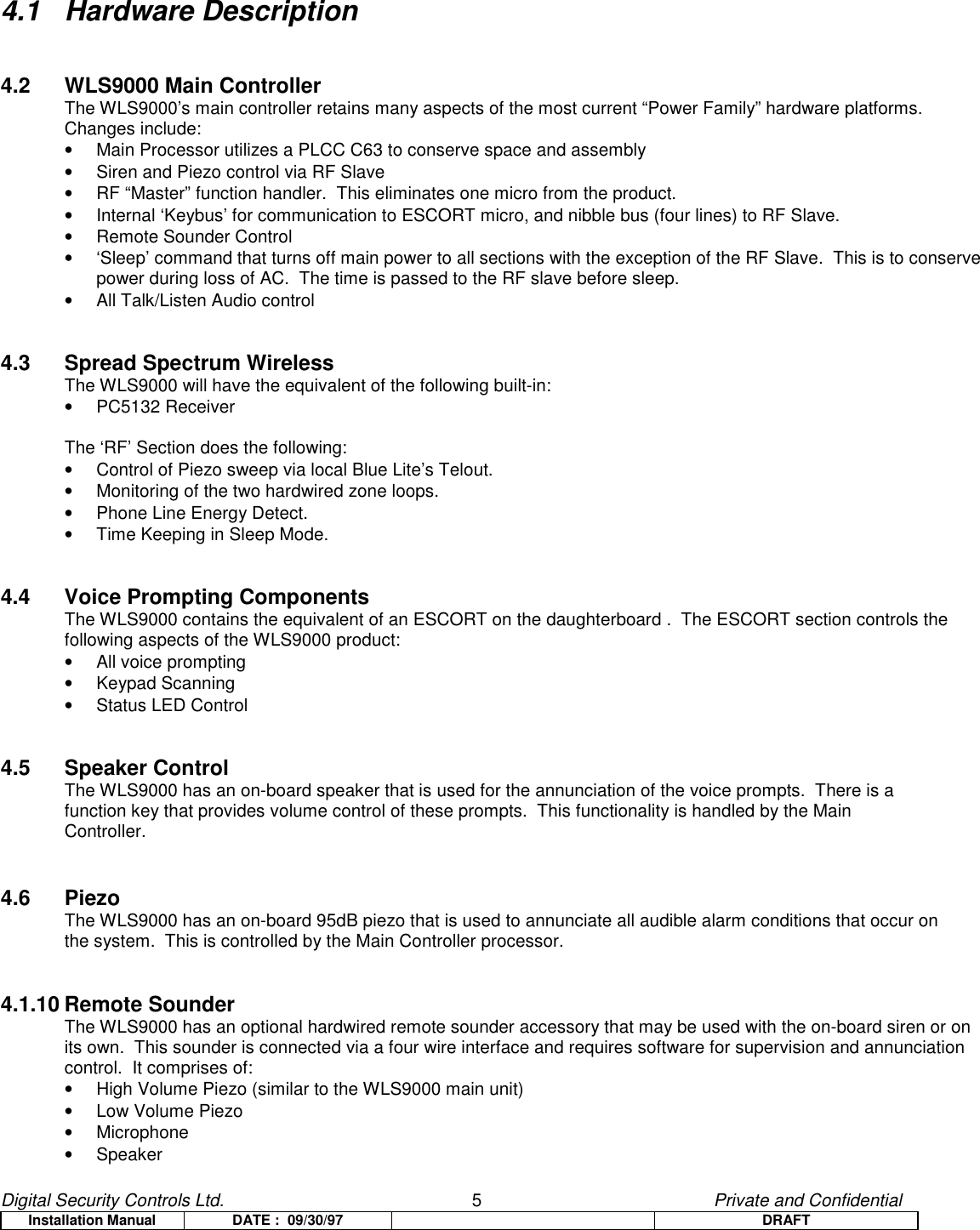
![Digital Security Controls Ltd. 7 Private and ConfidentialInstallation Manual DATE : 09/30/97 DRAFTThe WLS9000 will also use the Acuity Shroud (08-686) for supporting the microphone on the main unit.iiThe Remote Sounder will use the existing WLS902/911 Wireless Sounder plastics. They comprise of:• RF Siren Case Front (08-166)• RF Controller/Siren Strain Relief (08-223)• RF Siren Jack Cover (08-225)• RF Siren Wall Mounting Plate (08-643)• Sounder Back Cover (08-746)5.0 Detailed Description of Software Feature Set5.2.1 New Function Key TypesThe WLS9000 has the following new Function Key Types:Status –The Status button on the WLS9000 may be pressed to annunciate the current status of the system. Forexample:“Zones are open. Zone 1. System is OFF. To turn ON, enter your access code. Formore options, press star.”iiiPressing this key will internally create a link between the panel, ESCORT5580, and audio portionsof the WLS9000. When voice help is active, the keypad may be used to change status or program anyfunction of the system. This new key is programmable on WLSKeys to allow wireless initiation of Status.Status is function key definition [27], and will use Mode Request %1C.Volume Control – A new function key has been created to allow easy volume control of the voice prompts. Whenthis function key is pressed for two seconds, the WLS9000 will increment through the four different volumelevels from lowest to highest, cycling back to the lowest after the highest volume is reached.For example, if the Volume key is pressed for two seconds, and the current Volume is Medium, theWLS9000 will prompt:“Volume is High.”…at the new volume. If the key is held for another two seconds, the WLS9000 will state:“Volume is Highest.”…and so on.iv This Function Key is Type [28], and uses Mode Request %1D.Note: this function key only controls the volume of the main WLS9000 unit. Volume for the ESCORTprompts heard via the phone line are still handled in [*][6].Memo Record – When pressed, this function key will initiate recording (via the local microphone) of a message.Recording begins after the three acknowledgement tones are annunciated. The recording can also be endedby pressing this same function key. This Function Key is Type [29], and uses Mode Request %1E.Memo Playback – When pressed, this function key will annunciate the recorded message. If there is no message](https://usermanual.wiki/Tyco-Safety-Canada/99SS9001/User-Guide-68638-Page-7.png)
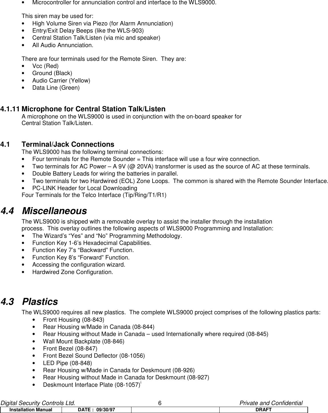
![Digital Security Controls Ltd. 8 Private and ConfidentialInstallation Manual DATE : 09/30/97 DRAFTrecorded, an error tone will be heard. This Function Key is Type [30], and uses Mode Request %1F.5.2.2 Installer Programming ‘Wizard’In order to facilitate an easy method to program the WLS9000, a Front End Installer’s Programming Wizard isimplemented into the WLS9000.The Wizard is designed to:• Accommodate the requirements of the mass marketer (i.e. 4-10 devices per system)• Reduce installation time, even for those who may not be familiar with the DSC line of Products.• Reduce the possibility of Programming errors.• Provide easy RF and Hardwired Zone enrollment and placement.5.2.2.1 Serial Number ProgrammingOnce Installer’s Programming is successfully entered, and the Wizard selection is made, the Installer will beprompted to enter the Serial Number of their first device. After the number is confirmed, the software will analyze thenumber and make the following programming change based off of the Serial Number entered:Transmitter Type Definition Other2 (UTX) Define as Delay 1 (Type [01])3 (Detector) Define as Interior Stay/Away (Type [05])4 (Smoke) Define as Delayed 24 Hour Fire (Type [87])5 (Panic Pendant) Define as 24 Hour Panic (Type [16]) Disable Zone Supervision (Section[804])Note: this chart is the Programming Actions found in the Wizard Flowchart provided by Marketing.Hardwired Zone ‘Enrolling’ – The Wizard can also be used to enroll Hardwired zones. Serial Numbers X00001and X00002 have been reserved for the two on-board zones.When a zone is enrolled in the Wizard as one of these zones, the WLS9000 will automatically assign the nextavailable zone number and enter it in Section [020].For example, if the Installer entered 200001 as the seventh zone, the WLS9000 will assign Zone 7 as being thefirst Hardwired zone in Section [20] (first entry 07).Note: Production must be advised to no longer use X00001 and X00002 as active serial numbers.5.2.2.2 Zone Label ProgrammingIf an enrolled device is a detector (i.e. not a WLSKey nor HHK), the Wizard will then prompt the Installer to enterthe Zone Label for the newly enrolled zone.The WLS9000 has five presets for each type of detector programmed that may be selected via pressing the “A” to“E” keys. Pressing the “F” key will allow the Installer to manually program the label from a chart found in themanual.The preset table is as follows:Selection Type 2 (UTX) Type 3 (Detector) Type 4 (Smoke) Type 5 (Panic Pend)“A” Preset Front Door Main Floor Motion Main Floor Fire No Presetsv“B” Preset Back Door Upstairs Motion Upstairs Fire“C” Preset Garage Door Downstairs Motion Downstairs Fire“D” Preset Window Hallway Motion Hallway Fire“E” Preset Patio Door Garage Motion Garage FireAs soon as a Label is programmed (and confirmed) either via Preset or manual entry, it is immediately stored inEEPROM.](https://usermanual.wiki/Tyco-Safety-Canada/99SS9001/User-Guide-68638-Page-8.png)
![Digital Security Controls Ltd. 9 Private and ConfidentialInstallation Manual DATE : 09/30/97 DRAFT5.2.2.3 Communications ProgrammingAfter all of the Serial Numbers have been entered, The Wizard will proceed into Communications Programming.Here the Installer is prompted for the First Telephone Number and it’s corresponding Account Code. As with allWizard Programming, each data entry is followed by a confirmation routine to ensure the data is properly entered.5.2.2.4 Module Placement TestThe Module Placement Test of the WLS9000 is quite different from previous Power-Based products as itincorporated the following changes and enhancements:• Each Detector Must pass three Consecutive Tests before being enabled on the system.• Each Detector is enabled in Section [202]-[205] only after passing the three tests mentioned above. There is noway to manually override this enrollment process.• There are only “Good” and “Bad” Placements. “Fair” has been removed; it’s former status internal to thesoftware is considered a “Bad”.• The piezo will squawk once for “Good” and three times for “Bad”.• If the Placement is exited before all zones are properly enrolled, a General System Trouble is generated at thekeypad. This trouble can only be cleared by re-entering the Module Placement Test and testing the un-enrolleddevices.• Zones can be disabled via Section [202]-[205], but they cannot be enabled.When Module Placement Test is entered, the system will annunciate all of the zones which have been enrolled onthe system, but are not enabled in Sections [202]-[205]. This allows the Placement Test to be entered afteradditional devices have been enrolled on the system without the hassle or re-testing ‘placed’ zones.As each device receives three “Good” placements, it is removed from the annunciation list and it’s corresponding bitin Section [202]-[205] is toggled to enable the zone on the system.After all zones have passed the Module Placement Test, the Wizard will end and the Installer will find him/herself inbase Standard Programming, where he/she may do additional programming not covered by the Wizard. “#” may bepressed to exit.5.2.3 Internal or External Annunciation SelectionA method of selecting either the internal piezo/speaker or external remote sounder for the annunciation ofalarms and Audio has been implemented in the WLS9000. This feature is to deter thieves from “homing in” on thesource of the alarm and tampering with the WLS9000, thus resulting in a potential security breech.The settings are as follows:• Local Annunciation (main unit: Section [040] Option 1)• Remote Annunciation (Remote Sounder: Section [040] Option 2)• Both (Section [040] Options 1 and 2 ON)This feature is found in Section [040], Options 1 and 2, with Option 1 defaulted ON and Option 2 defaulted OFF.5.2.4 Voice PromptingThe WLS9000 will have a complete library of prompts similar to the ESCORT5580 to assist the user through variousfunctions of the system. This will also include Installer programming prompting similar to ESCORT programming inthe ESCORT5580.5.2.5 Volume of AnnunciationThere is several different levels of volume for the on-board piezos and speaker.• Full Siren (siren; as loud as possible for alarm conditions)• Full Voice (speaker; used to verbosely annunciate alarms. Always = highest speaker volume setting)• Conversational Audio (speaker; Voice Prompted Help = four selectable levels)• Low “Beeps” (small piezo; trouble conditions)The volume of the voice prompts may be selected one of two ways:• Using the Volume Function Key (Type [28]) to toggle through the different volume settings.](https://usermanual.wiki/Tyco-Safety-Canada/99SS9001/User-Guide-68638-Page-9.png)
![Digital Security Controls Ltd. 10 Private and ConfidentialInstallation Manual DATE : 09/30/97 DRAFT• Within [*][6] User Programming under selection 7.5.2.7 Verbal ChimeA feature has been added to the WLS9000 that allows Door Chime to annunciate the Zone that has beenviolated/restored as opposed to a series of beeps.If the Verbal Chime Feature is enabled, whenever a zone with the Chime attribute enabled is violated, a series ofbeeps will sound and the WLS9000 will prompt:“Zone X”When the zone is restored, the WLS9000 will only sound a series of beeps similar to how Door Chime functions inour current products.If a label was programmed for the above Zone, the WLS9000 would annunciate (after the beeps):“Back Porch Window”…and so on.If this option is disabled, only the series of beeps will be heard upon the violation and restore of zones that areprogrammed to chime. If Chime is disabled via [*][4], no beeps nor prompts will be heard.This option can be found in Section [017], Option 2, and is enabled (ON) at default.5.2.8 Verbal AlarmA feature has been added to the WLS9000 that provides verbal annunciation of alarm conditions on the system.When an audible non-fire zone goes into alarm with this feature is enabled, the WLS9000 will sound the alarmcondition via the high volume piezo, but every 5 seconds (as programmed for Alarm Tone Period – Section [807],Subsection [030])vi it will pause siren and the speaker an annunciate the alarm condition verbally:“Alarm Zone 4”or, if the label is programmed,“Alarm South Bedroom Window”When the zone is in alarm, the software automatically inserts the word “Alarm” in front of the appropriate zone label.When an audible fire zone goes into alarm, the WLS9000 will sound the alarm condition via the high volumepiezo, but every 5 seconds (as programmed for Alarm Tone Period – Section [807], Subsection [030]) itwill pause siren and the speaker an annunciate the alarm condition verbally:“Fire Alarm Zone 4”or, if the label is programmed,“Fire Alarm South Bedroom Smoke”When the zone is in alarm, the WLS9000 automatically inserts the words “Fire” and “Alarm” in front of theappropriate zone label.In the case of multiple alarms, the WLS9000 will annunciate the first and latest zone that has gone into alarm.Fire Zones will override Burglary Zones, similar as a Pulsing Bell will override a steady one.This option can be found in Section [017], Option 3 and is enabled (ON) at default.Notes: Fire annunciation always overrides any Burglary Zone alarm annunciation.Verbal Alarm will cease with the Siren at Bell Time Out.](https://usermanual.wiki/Tyco-Safety-Canada/99SS9001/User-Guide-68638-Page-10.png)
![Digital Security Controls Ltd. 11 Private and ConfidentialInstallation Manual DATE : 09/30/97 DRAFT5.2.9 Function Keys While in Installer’s ProgrammingIn order to facilitate a more Installer-friendly user interface, the Eight Function Keys of the WLS9000 will performthe following functions in Installer’s Programming:FunctionKey Number Default Function KeyOption Installer’sProgramming Function Used For:1 Stay Hexadecimal ‘A’2 Away Hexadecimal ‘B’3 Chime Hexadecimal ‘C’4 Exit Hexadecimal ‘D’5 Status Hexadecimal ‘E’6 Volume Hexadecimal ‘F’Programming thecorresponding Hex Entryfor Account Codes,Reporting Codes, PhoneNumbers, etc.7 Memo Record Forward Moving ahead in theProgramming Wizard.8 Memo Playback Back Moving backwards in theProgramming Wizard.• Pressing any key that performs hexadecimal functions will generate a ‘Function Not Available” prompt if thecurrent section does not support Hex entries.• The Forward and Back keys are used for:1. Reviewing and editing previously entered data.2. Advancing through sections to get to a certain Wizard Section.Note: Only the Forward Key can be used outside of the Wizard.5.2.10 Memo FeatureThe WLS9000 will have a feature that allows the recording and playback of a verbal memorandum.A user, while armed or disarmed, can record a memo via the “Memo Record” function key. To record a memo, press and hold the Memo Record key for two seconds. After the acknowledgement beeps,speak the desired message in the direction of the WLS9000. When finished, press the “Memo Record” functionkey again (note: the two second debounce is not required here).To hear the last memo recorded, press and hold the “Memo Playback” key for two seconds.Note: Although the target record duration is 60 seconds, the exact numbers are under development by theSoftware department.5.2.11 Recording of Custom LabelsThe WLS9000 has the capability of recording custom labels that may be assigned to a zone like any otherESCORT Label. Labels [246] to [253] are reserved for Custom Labels 1-8.These labels can be recorded via Installer’s Programming in Sections [701]-[708] using the following format:When in Sections [701]-[708], the ‘Record’ key (Function Key 7) may be pressed to begin recording. After thedesired label is verbally annunciated by the Installer, ‘Playback’ (Function Key 8) may be pressed to end therecording and annunciate the label. ‘Playback’ can be pressed again to re-annunciate the Labelrecording.Notes: Even if Function Keys 7 and 8 have been reprogrammed, they will still retain the same above functions inthese sections.The quantities and length of the labels recorded will directly affect the total amount of time that a Memocan be recorded. This is due to the fact as they share the same resources.](https://usermanual.wiki/Tyco-Safety-Canada/99SS9001/User-Guide-68638-Page-11.png)
![Digital Security Controls Ltd. 12 Private and ConfidentialInstallation Manual DATE : 09/30/97 DRAFT5.2.13 Function Key Programming in ESCORT ProgrammingviiFunction Key programming has been moved out of the main panel and into Section [807], Sub-section [000]. Thishas been done in order to keep the corresponding programming in the ESCORT section of the product. Thisallows the desired functionality to be obtained without major impact to the existing architecture of the software.5.2.14 New LogsviiiIn order to support the new Module Placement functionality, a new log has been implemented for:Event %1D5 Module Placement Test Unsuccessful8.0 Functional Description of…8.1 Standard FeaturesTWO MINUTE BYPASS ON POWER UPWhen power is first applied to the system, all zones will be bypassed for two minutes. This is to allow time for thedevices to “settle” without causing false alarms. If after 2 minutes any zones are still unrestored, they will bedetected as open and will generate the respective alarm sequence, if applicable.ALARMS ANNUCIATED WHILE ARMEDZone Alarm conditions will be annunciated on all the WLS9000 by Verbally annunciating them as they occur.This also occurs for 24 Hour alarms while disarmed.ACCESS CODE REQUIRED TO CANCEL AUTO ARMINGAn access code must be entered to cancel (postpone) the Auto-Arm sequence during the 1-minute Auto-ArmWarning time.HARDWIRED ZONE LOOP RESPONSE TIMEThe hardwired zone loop response time is fixed at approximately 500ms.Note: The WLS9000 hardwired zones require a single 5.6K EOL resistor.TIME-OUTSThe general system time-out for Installers mode is 20 minutes. If the unit is left in Installer’s for twenty minuteswithout a keypress, it will return to its base menu.SILENT EXIT DELAY IF STAY ARMINGIf the system Stay armed using any of the following methods, all audible exit features (keypad buzzer) that areenabled will be silent for the exit delay time. Bell Squawk on Exit Delay will also be silent if Home or [*][9] Armed.Bell Squawk on Arm/Disarm will still sound regardless of how the panel is armed/disarmed.[*][9][Access Code][Stay Arm Function Key (Option 03)][No Entry Arm Function Key (Option 05)]SPECIAL ENTRY IF ALARM IN MEMORYIf any entry delay begins on the system and there are alarms in memory, the entry tone shall sound a pulsing tone for the entire entry delay (as per Entry Delay Urgency).SWINGER SHUTDOWN RESETIf Swinger Shutdown is enabled on the system, all counters will be reset when the system time changes from 23:59 (11:59 PM) to 00:00 (12:00 AM) OR any time the system is armed (expiration of the exit delay).ENTRY DELAY URGENCY](https://usermanual.wiki/Tyco-Safety-Canada/99SS9001/User-Guide-68638-Page-12.png)
![Digital Security Controls Ltd. 13 Private and ConfidentialInstallation Manual DATE : 09/30/97 DRAFTThe keypad will sound a steady tone during the Entry Delay. During the last 10 seconds of the Entry Delay, thekeypad buzzer will sound a pulsing tone (3 tones per second) to warn that the Entry Delay is about to expire.SIREN FOLLOWS SWINGER SHUTDOWNThe siren will not be activated for alarms on zones that have exceeded the limit of alarms set in the SwingerShutdown counter.ROTATING KEYPRESS BUFFER ON DISARMThe WLS9000 has a method to solve the problem of someone entering a code to disarm and getting out ofsequence. The end result of this on other products when the user does not press [#] before re-entering their code isa false alarm. What the panel does now is look for any 4 digits in a row which match a valid code. If this is deemeda security risk, Keypad Lockout can be enabled and every fourth or sixth key will count as one bad attemptdepending on the code length. The panel includes this feature while disarmed with the Bell active. This is useful foraudible alarms that may occur in the disarmed state. This feature is hardcoded.CROSS ZONE POLICE CODEThis event is logged and the reporting code is transmitted to the central station (if enabled) when there are twodifferent alarms during any armed-to-armed period. This means that if there is one alarm while the panel is armed,and a second alarm on a different zone after it is disarmed, this code will still be sent. Previous software versionsused to transmit this event for any two different alarms during either an armed or disarmed period, but NOT on acombination of both.If two different zones are violated, if both or either have them have the Transmission Delay Attribute enabled, thenthe transmission of the Cross Zone Police Code should be delayed for the appropriate time programmed. If neitherof the two zones have Transmission Delay, then the Cross Zone Police Code should be transmitted immediately withthe two zone alarms.IDENTIFIED WIRELESS KEY ARMING/DISARMINGA method has been developed to identify openings and closings by Wireless Keys. This has been done by relatingeach Key to an access code. Wireless Keys 1 to 16 are represented by Access Codes 17 through 32 respectively. Ifone of these access codes are programmed via [*][5] programming in the WLS9000, the panel will then log andtransmit the opening/closing by access code, as opposed to opening/closing by keyswitch.Note: The Function Keys Require Code Option must be on (Section [015], Option 4 OFF) in order for Wireless Keysto be identified for arming. Disarming will always be logged by access code, if one is programmed for the Key,regardless of this option.PANIC PENDANT TESTWhen a Pendant Test is executed, the WLS9000 will sound a steady 1 second tone.Note: the LED update is not kept up for the duration of the test. The WLS9000 will not be returned to the ready statefor 30 seconds or when the “#” key is pressed.ONE TIME RESTART OF EXIT DELAYA hardcoded feature has been implemented that allows a single restart of the exit delay with the press of theAway key during the Exit Delay. This feature will not be permitted if Arming With No Entry ([*][9]) or with the Staykey.HARDWARE DEFAULTixThe WLS9000 may be defaulted via hardware by shorting the Remote Sounder Data Terminal (Green) to Black. Theshort must be present for 1 second on power-up for the system to properly default.Note: This only defaults the main controller. All other defaulting must be done individually through Installer’sProgramming.8.2 Feature Set](https://usermanual.wiki/Tyco-Safety-Canada/99SS9001/User-Guide-68638-Page-13.png)
![Digital Security Controls Ltd. 14 Private and ConfidentialInstallation Manual DATE : 09/30/97 DRAFT8.2.1 Zone Definitions [001]-[004] Each of these sections require 8 two digit entries. Each two digit number entered describes how a zone willoperate.00 Null Zone is for zones that are not used and does not require a closed loop or EOL resistor01 Delay 1 follows the Entry Delay 1 and Exit Delay programmed in Section [005] and is normally used for Entry/Exit doors. The exit delay starts as soon as the panel is armed. The zone may be opened and closed during the delay time without causing an alarm. After the exit delay time has expired, opening the zone will start the Entry Delay timer. During the Entry Delay time, the keypad buzzer will sound steadily to advise the user that the system should be disarmed. If the panel is disarmed before the Entry Delay expires, no alarm will be generated.02 Delay 2 operates the same as Type [01] zone except the Entry Delay time can be independently set in Section [005]. The Exit Delay time is common to both zone types. 03 Instant is normally used for door and window contacts and has the standard Exit Delay, but is instant when opened after the Exit Delay expires.04 Interior are used with interior motion detectors. Interior zones feature both an Exit Delay and an Entry Delay provided that any Delay type zone has been tripped first. If the protected area is entered without coming through the a delayed entrance and an Interior zone is tripped, an immediate alarm will be generated.05 Interior Stay/Away. If the system is armed and a Delay zone is NOT tripped during the exit delay time, this zone type will be bypassed. If the [*][1] command is used to activate all Stay/Away type zones, this zone will have the standard exit delay. Once armed, this zone will act like an Interior type zone [04]. 06 Delay Stay/Away If the system is armed and a Delay zone is NOT tripped during the exit delay time, this zone type will be bypassed. If the [*][1] command is used to activate all Stay/Away type zones, this zone will have the standard exit delay. Once armed, this zone will always have follow the Entry Delaytime for Entry Delay 1 when tripped.Note: The automatic bypass on Stay/Away type zones will not be removed by any event otherthan a valid exit through a Delay type 1 zone during the exit delay or by pressing [*][1] whilearmed.07-08 Not Used x10 24 Hour Supervisory Buzzer is active at all times and will report an alarm at all times. Once tripped, the keypad buzzer will sound until a valid access code is entered. If configured for Global operation, an access code will be required on each partition to silence the buzzer on the corresponding partition.Note: This zone type should not be used on a Keyswitch ONLY system.11 24 Hour Burglary is active at all times and will report an alarm if the panel is armed or disarmed. This type will sound the bell for the length of Bell cutoff if the audible attribute is enabled.12 24 Hour Holdup is similar to 24 Hour Burglary except for System Event output type and SIA identifier.13 24 Hour Gas is similar to 24 Hour Burglary except for System Event output type and SIA identifier.14 24 Hour Heat is similar to 24 Hour Burglary except for System Event output type and SIA identifier.15 24 Hour Medical is similar to 24 Hour Burglary except for System Event output type and SIA identifier.16 24 Hour Panic is similar to 24 Hour Burglary except for System Event output type and SIA identifier.](https://usermanual.wiki/Tyco-Safety-Canada/99SS9001/User-Guide-68638-Page-14.png)
![Digital Security Controls Ltd. 15 Private and ConfidentialInstallation Manual DATE : 09/30/97 DRAFT17 24 Hour Emergency is similar to 24 Hour Burglary except for System Event output type and SIA identifier.18 24 Hour Sprinkler is similar to 24 Hour Burglary except for System Event output type and SIA identifier.19 24 Hour Water is similar to 24 Hour Burglary except for System Event output type and SIA identifier.20 24 Hour Freeze is similar to 24 Hour Burglary except for System Event output type and SIA identifier.21 24 Hour Latching Tamper. This zone type, when violated, will cause arming of the system (both partitions) to be inhibited until the valid Installer code is entered. If this zone type is violated, the Installers code must be entered ([*][8] Installers Code) before the system can be armed.22 Momentary Keyswitch Arm. A keyswitch module may be connected to the zone programmed as Momentary Keyswitch arm. Momentary activation of this zone will alternatively arm and disarm the system and silence alarms. Note that the keypad will not display an indication when this type of zone is activated.23 Maintained Keyswitch Arm. A Normally Open Keyswitch module may be connected to the zone programmed as Maintained Keyswitch arm. In the restored state, the panel is disarmed. Any violation of the zone will cause the system to arm (Alarm, Tamper, Fault).24-26 Not Used87 Delayed 24 Hour Fire (Wireless) works the same way as the Standard fire zone, except the alarm memory and transmission by the communicator is delayed by 30 seconds. If the alarm is acknowledged by pressing any key within 30 seconds, the bells will silence and the transmission will be aborted. If afterthe alarm has been acknowledged, and the smoke detector has not been restored to normal, after 90seconds the bell output will be activated again, in which the user then has another 30 second delay beforethe bell output latches and communications is activated. A code would then be required to silence the belloutput.Note: The Fire Delay will be terminated if a 2nd Fire zone is tripped or if the [F] key is pressed during adelay.88 Standard 24 Hour Fire (Wireless) is a fire zone that is specially used for pull station type circuits. On alarm, the bell output will sound to indicate that the fire loop has been activated. If enabled, the communicator will immediately transmit the alarm to the monitoring station.Note: For all Fire type zones the Zone Attributes should not be changed from the defaultsettings.8.2.2 System Times [005]This section requires 4 three digit entries.Note: Entry of 000 in these sections will result in 255 second times.Entry Delay 1: (001-255) SecondsThis value determines the Entry delay time for Delay 1 type zones. The default Entry Delay 1 time is 30 seconds.Entry Delay 2: (001-255) SecondsThis value determines the Entry delay time for Delay 2 type zones. The default Entry Delay 2 time is 45 seconds.Exit Delay: (001-255) Seconds](https://usermanual.wiki/Tyco-Safety-Canada/99SS9001/User-Guide-68638-Page-15.png)
![Digital Security Controls Ltd. 16 Private and ConfidentialInstallation Manual DATE : 09/30/97 DRAFTThe system will use one common exit delay time that must be programmed to accommodate the longest possible exit time required. The default Exit delay time is 120 seconds.Bell Cut-off: (001-255) MinutesThis value determines the time the bell / siren will sound before automatically turning off. The default bell cutoff time is 4 minutes.Alarms/Events which cause the Keypad Buzzer to sound (System Tampers, 24 Hour Buzzer Zone, etc) do not follow this Bell Cutoff Timer. The buzzer will sound until an access code is entered to silence the condition.8.2.3 Special Access Codes [006]-[008] Each of these sections require 4 or 6 digits to be entered.Installer’s Code.Master Code.Maintenance Code. This is a Arm/Disarm only code. It can not be used to bypass program other usercodes or enter the [*][6] menu. Openings or Closings using this code report as a Special Opening/Closingand will log to the event buffer as “Maintenance Code”.8.2.4 Keypad Lockout Options [012] This section determines how the keypad lockout function operates.Number of Invalid Codes Before LockoutProgram a number from 000 to 255 to determine the number of invalid master, duress, user or installer access code entries to reach keypad lockout. When keypad lockout occurs, the system is rendered inoperative via keypad for the programmed duration. When any keys are pressed, an error tone willsound. Entering 000 disables the feature.Lockout DurationProgram a time from 000 to 255 minutes to determine the length of time before lockout resets and the keypad can once again be used. Note: If lockout is not reached within the hour roll-over, the number of invalid attempts is resetto 0.FAP keys are still active during Keypad Lockout.8.2.5 System Options Codes[013] First System Options Code[1] Hardwired Zone Supervision OptionON = Hardwired Zones are EOLBoth hardwired zone loops on the WLS9000 use EOL supervision.OFF = Hardwired Zones are Normally ClosedBoth hardwired zone loops on the WLS9000 use Normally Closed loops.[2]-[3] Not Used[4] Tampers/Faults Annunciation OptionON = Tampers and Faults Do Not Annunciate as OpenThe panel will not annunciate the respective Zone if the zone is in the Tamper or Fault states,](https://usermanual.wiki/Tyco-Safety-Canada/99SS9001/User-Guide-68638-Page-16.png)
![Digital Security Controls Ltd. 17 Private and ConfidentialInstallation Manual DATE : 09/30/97 DRAFTonly the Trouble LED will be on.OFF = Tampers and Faults Annunciate as OpenThe panel will annunciate the respective Zone if the zone is in the Tamper or Fault states.The Trouble LED will also be lit.[5] Not Used[6] Audible Exit Fault OptionON = Audible Exit Fault is Enabled.If a non force-armable Delay 1 or Delay 2 type zone is left open at the end of the Exit Delay, theEntry Delay will begin immediately and the bell or siren will sound a steady alarm for the timeprogrammed as Bell Timeout. This feature is designed to immediately alert the user that theirsystem has been armed incorrectly.OFF = Audible Exit Fault is Disabled.Note: For [*][9] arming, if Audible Exit Fault is enabled a violated zone will begin entry delay asper Audible Exit Fault functionality. If this option is disabled, a violated delay zone at the end ofthe exit delay will cause an instant alarm.[7] Event Buffer Swinger OptionsON = Event Buffer Follows Swinger Shutdown.Once an event reaches its Swinger Shutdown limit programmed in Section [370], it will no longerlog to the Event Buffer until the Swinger Shutdown is reset. This avoids filling the Event Bufferwith useless events.OFF = Event Buffer Logs Events past Swinger Shutdown.[8] Fire Signaling OptionsON = Temporal Three Fire Signal.In order to comply fully with NFPA 72, all Fire Bells will sound in the Temporal Three Pattern asdescribed in the NFPA standard if this option is enabled. This cadence is as follows: 500ms ON,500ms OFF, 500ms ON, 500ms OFF, 500ms ON, 1.5 s OFF.OFF = Standard Pulsed Fire Signal.All fire bells will sound with the standard 1 second on/1 second off fire bell cadence.[014] Second System Options Code[1] Bell Squawk OptionsON = Arm / Disarm Bell Squawk Enabled.The Bell output will sound a single squawk when armed in any manner, incl Auto-arm, and adouble squawk upon disarming the system. If there are alarms in memory, the bell will emit a seriesof three squawk pairs to indicate the alarm memory.OFF = Arm / Disarm Bell Squawk Disabled.The Bell output will not squawk when the system is armed or disarmed in any manner.[2] Bell During Auto-Arm OptionsON = Bell Squawk During Auto-Arm Enabled.The Bell output will sound a single squawk every 10 seconds during the 1 minute Auto-Arm Pre-alert time.OFF = Bell Squawk During Auto-Arm Disabled.The Bell output will not be activated during the 1-minute Auto-Arm warning time.[3] Bell Squawk On Exit OptionsON = Bell Squawk On Exit Delay.The Bell output will squawk once per second during the Exit Delay time. The bell will also sound3 squawks per second for the final 10 seconds.OFF = No Bell Squawk On Exit Delay.Note: This audible option applies to ALL manual arming modes (Stay, Away, No Entry, etc)](https://usermanual.wiki/Tyco-Safety-Canada/99SS9001/User-Guide-68638-Page-17.png)
![Digital Security Controls Ltd. 18 Private and ConfidentialInstallation Manual DATE : 09/30/97 DRAFT[4] Bell Squawk On Entry OptionsON = Bell Squawk On Entry Delay.The Bell output will pulse with the same timing as the keypad buzzer during the Entry Delay time.The bell will sound 3 squawks per second for the final 10 seconds if Option 6 in this section isenabled.OFF = No Bell Squawk On Entry Delay.[5] Bell Squawk on Trouble OptionsON = Bell Squawks on Trouble.Whenever there is a Trouble condition enunciated on the system keypads, the Bell will squawk 2times every 10 seconds (as per the keypad buzzer). The Bell will be silenced when the keypadbeeps are silenced (any key pressed on keypad).OFF = No Bell Squawks on Trouble.[6] Audible Exit BeepsON = Audible Exit With Urgency.The keypad will sound a pulsing tone (once per second) during the Exit Delay. For the last 10seconds of the Exit Delay, the keypad and bell / siren (if enabled) will sound a different tone (3 tonesper second) to warn that the Exit Delay is about to expire.OFF = Silent Exit Delay.The keypad will not sound during the Exit Delay.[7] Exit Delay Termination OptionsON = Exit Delay Termination Enabled.The Exit Delay will be terminated once a Delay 1 Zone for the entry/exit door or area is restored. Allaudible options associated with the exit delay will be silenced when the Exit Delay is terminated.Force-Armable Delay 1 type zones will also terminate the exit delay.OFF = Exit Delay Termination Disabled.The Exit Delay timer will continue to count even after the Delay Zone for the entry/exit door or area isrestored. All audible options associated with the Exit Delay will function until the time programmedfor the Exit Delay has elapsed.[8] Fire Bell Timeout OptionsON = Fire Bell is Continuous.For all Fire type alarms, the Bell output will sound until an access code is entered to silence thealarm or disarm the system regardless of the time programmed for Bell Timeout in Section [005].OFF = Fire Bell Follows Timeout.For all Fire type alarms, the Bell output will sound for the length of Bell timeout or until an accesscode is entered.[015] Third System Options Code[1] [F] Key OptionsON = [F] Key Enabled. Pressing and holding the [F] keys for 2 seconds will generate a Fire alarm. The keypad will sound aset of 3 beeps to acknowledge the valid alarm and the bell or siren will sound with a pulsing tone forthe length of Bell time-out. An alarm reporting code (if programmed) will be transmitted.OFF = [F] Key Disabled.The [F] key will not sound or report an alarm when pressed.[2] [P] Key Annunciation OptionsON = [P] Key Audible.When a valid [P] key alarm is generated, the Keypad buzzer will sound a series of 3 beeps to acknowledge the alarm and the bell or siren will sound for the length of Bell timeout.OFF = [P] Key Silent.](https://usermanual.wiki/Tyco-Safety-Canada/99SS9001/User-Guide-68638-Page-18.png)
![Digital Security Controls Ltd. 19 Private and ConfidentialInstallation Manual DATE : 09/30/97 DRAFTWhen a valid [P] key alarm is generated, the Keypad buzzer and the bell output will remain silent,but the alarm transmission will still be transmitted (if programmed).[3] Quick Exit OptionsON = Quick Exit Enabled.When the system is armed, users may enter the [*][0] Command to allow a single Delay 1 or Delay 2Zone to be activated so they may leave the premises. Only one Delay zone may be activated; anyadditional activity on another Delay zone will cause its respective alarm sequence. If the Delay zoneis still open two minutes after the [*][0] command is entered, the Entry Delay will be initiated. Ifarmed in the Stay mode, the automatic bypass on Stay/Away zones will not be removed.OFF = Quick Exit Disabled.[4] Quick Arming/Function Key OptionsON = Quick Arming Enabled/Function Keys Do Not Require Code. [*][0] arming and Stay/Away Function Keys may be used to arm the system without theentry of a valid access code. All other function Keys may also be used without the entry of anaccess code.OFF = Quick Arming Disabled/Function Keys Require Code.[*][0] arming is not permitted, and all Function Keys require the entry of an access code toactivate (including Stay/Away keys).[5] Bypass Access Code OptionsON = Access Code Required to Bypass Zones.After entering the [*][1] Bypass Zones Command, an access code must be entered before zonesmay be bypassed.OFF = Access Code Not Required to Bypass Zones.Enter the [*][1] Bypass Zones Command to bypass zones.Note: this option is supplemental to Option 4.[6] Master Code OptionsON = Master Code Not User Changeable.The Master Code (Access Code 40) may not be changed by the user, and may only be programmedin the Installer’s Programming Mode.OFF = Master Code User-Changeable.The Master Code (#40) may be programmed by the user using the [*][5][Master Code] command.The Master Code may also be programmed in the Installer’s Programming Mode.[7] Telephone Line Monitor OptionsON = Telephone Line Monitor enabled.The TLM function will be active and the system will indicate a Trouble #3 condition when using the[*][2] View Trouble Conditions Command.OFF = Telephone Line Monitor disabled.The TLM function will be shut off and telephone line troubles will not be indicated by the system.[8] Telephone Line Monitor Trouble OptionsON = TLM Audible When Armed.When the system is disarmed, a telephone line monitor trouble will generate a trouble indication asdescribed above. If the system is armed, a telephone line monitor trouble will generate an audiblealarm on the bell or siren for the duration programmed for Bell Timeout or until an access code isentered to disarm.OFF = TLM Trouble Only.A telephone line trouble will generate a trouble indication, the Trouble LED will come ON and thekeypad sounder will beep until a key is pressed.[016] Fourth System Options Code](https://usermanual.wiki/Tyco-Safety-Canada/99SS9001/User-Guide-68638-Page-19.png)
![Digital Security Controls Ltd. 20 Private and ConfidentialInstallation Manual DATE : 09/30/97 DRAFT[1]-[2] Not Used[3] Blanking OptionsON = Blank WLS9000 When Not Used.If no keys are pressed for 30 seconds, all on board lights except backlighting (if enabled) will be shutOFF until the next keypress, Entry delay, Audible Alarm or keypad buzzer condition.OFF = WLS9000 Always Active.The on-board lights will remain ON at all times.[4] Blanking Restore OptionsON = Access Code Required to remove WLS9000 Blanking.Before a blanked WLS9000 can be used, a valid access code must be entered.OFF = Access Code Not Required.Pressing any key on a WLS9000 will remove the blanking.[5] Backlighting OptionsON = Backlighting is Enabled.The system will have backlighting on all of the time.OFF = Backlighting is Disabled.[6] Not Used[7] Bypass Status Display OptionsON = Bypass Status Displayed While Armed.The Bypass status light will be ON if there are zones bypassed when the system is armed.OFF = Bypass Status Not Displayed While Armed.The Bypass light will be ON only while the system is disarmed to indicate that there are bypassedzones on the system. When the system is armed, the Bypass light will be OFF.Note: The Bypass status LED will be ON if there are Stay/Away zones auto bypassed at the timeof arming regardless of whether or not this option is enabled. This option only enables anddisables manual bypass display.[8] Not Used[017] Fifth System Options Code[1] WLSKey Disarming OptionsA toggle option has been added to prohibit the use the Disarm key on an unidentified Wireless Key.ON = WLSKeys Does Not Use Access Codes.The WLS9000 will accept the disarm keycode from an unidentified Wireless Key, thereby allowingarming/disarming without a code.OFF = WLSKeys Uses Access Codes.The WLS9000 will NOT accept the disarm keycode from an unidentified Wireless Key, thereby anaccess code must be associated to a WKEY for proper operation.[2] Verbal Door Chime OptionON = Verbal Door Chime is Enabled.The WLS9000 will verbally annunciate the zone (or programmed label) when it is eitherviolated or restored if Door Chime is programmed.OFF = Verbal Door Chime is Disabled.The WLS9000 will only annunciate a series of beeps whenever a zone programmed for Chimeis either violated or restored.](https://usermanual.wiki/Tyco-Safety-Canada/99SS9001/User-Guide-68638-Page-20.png)
![Digital Security Controls Ltd. 21 Private and ConfidentialInstallation Manual DATE : 09/30/97 DRAFTThis option is defaulted ON.[3] Verbal Alarm OptionON = Verbal Alarm is Enabled.The WLS9000 will verbally annunciate audible zone alarms via their zone number (or programmedlabel) in conjunction with the high volume piezo.OFF = Verbal Alarm is Disabled.The WLS9000 will only annunciate the high volume piezo during an audible alarm condition.This option is defaulted ON.[4]-[7] Not Used[8] Bell Squawk on Away Arming OptionON = Bell Squawk on Away Arming/Disarming OnlyBell Squawks will only be annunciated on Away Arming, as well as upon Disarming after being aredin the Away Mode.OFF = Bell Squawk on All Arming/DisarmingBell Squawks will be annunciated on all types of Arming and Disarming (if programmed in Section[014]).This feature is defaulted OFF.Notes: This feature is to prevent the Bell from being activated when arming from inside the premises. This option follows the “Bell Squawk on Arming/Disarming” and “Bell Squawk Attribute” features.8.2.6 Hardwired Zone Assignment [804] Subsections [71] and [72]xiThis section determines which zone number corresponds to the Hardwired zones found on the main unit.Enter the 2 digit zone number to be designated for each loop.Please note that this section has moved to Sections [71] and [72] of the RF Slave (Section [804]).Default[71] Hardwired Zone Loop #1 Assignment 00 I___II___I (Valid entries are Zones 01-32)[72] Hardwired Zone Loop #2 Assignment 00 I___II___I8.2.7 Remote/Local Annunciation Options (Section [017] Options 4 and 5)xiiNew toggle options have been added in Section [017] has been added to the WLS9000 that allows the Installer tohave alarm/audio annunciation at the Local Unit, Remote Sounder, or both.[4] Local AnnunciationON = Annunciation Sounds LocallyAll Audio and alarm annunciation is emitted from the main WLS9000 unit.OFF = Annunciation Does Not Sound LocallyNo alarm or audio annunciation is emitted from the main unit.This Option is defaulted ON.[5] Remote AnnunciationON = Annunciation Sounds RemotelyAll Audio and alarm annunciation is emitted from the Remote Sounder.OFF = Annunciation Does Not Sound RemotelyNo audio and alarm annunciation is emitted from the Remote Sounder.This option is defaulted OFF.8.2.8 Zone Attributes [101]-[132] The following options can be enabled or disabled by zone.](https://usermanual.wiki/Tyco-Safety-Canada/99SS9001/User-Guide-68638-Page-21.png)
![Digital Security Controls Ltd. 22 Private and ConfidentialInstallation Manual DATE : 09/30/97 DRAFT[1] Bell OptionsON = An alarm causes the bell output to activate.OFF = Silent Alarm.[2] Bell TypeON = The bell output will be steady when the zone is in alarm.OFF = The bell output will pulse when the zone is in alarm.[3] Chime OptionsON = The WLS9000 will chime both when the zone is violated and when the zone is secured. Door Chime will work in both the armed and disarmed states.OFF = The zone will not chime the keypads.[4] Bypass OptionsON = The zone may be manually bypassed.OFF = The zone cannot be bypassed.[5] Force Arming OptionsON = The system may be armed with the zone violated. The zone will be temporarily bypassed, and when the zone is secured it will be added back into the system.OFF = The partition cannot be armed if this zone is open.[6] Swinger Shutdown OptionsON = After the zone causes a programmed number of alarms, the zone will shut down so that no further transmissions are sent to the monitoring station. The bell can follow Swinger Shutdown if programmed.OFF = Swinger Shutdown disabled[7] Transmission Delay OptionsON = The reporting of zone alarms will be delayed for the programmed time. If a valid access code is entered within this time, no alarm signal will be communicated.OFF = When an alarm occurs, the reporting code is transmitted immediately.[8] Wireless OptionON = Zone is Wireless.All Zones on the WLS9000 are wireless with the exception of the two Hardwired loops. Enabled isthe default condition of all Zone DefinitionsOFF = Not UsedxiiiNote: Fire Zones attributes should not be changed. They should remain as defined by thedefault settings.[160] Maximum Dialing Attempts To Each Phone Number This value represents the number of attempts that will be made to each telephone number when communicating.The default value is 008 attempts. Valid entries are 001-015.[161] Post Dial Wait For HandshakeThis value represents the time the communicator waits for a valid initial handshake from the receiver after dialing the programmed telephone number. The default value is 040 seconds.[202]-[205] System Zone AssignmentsThese eight bit toggle section determines which zones on the system are enabled. All zones that are enabled will](https://usermanual.wiki/Tyco-Safety-Canada/99SS9001/User-Guide-68638-Page-22.png)
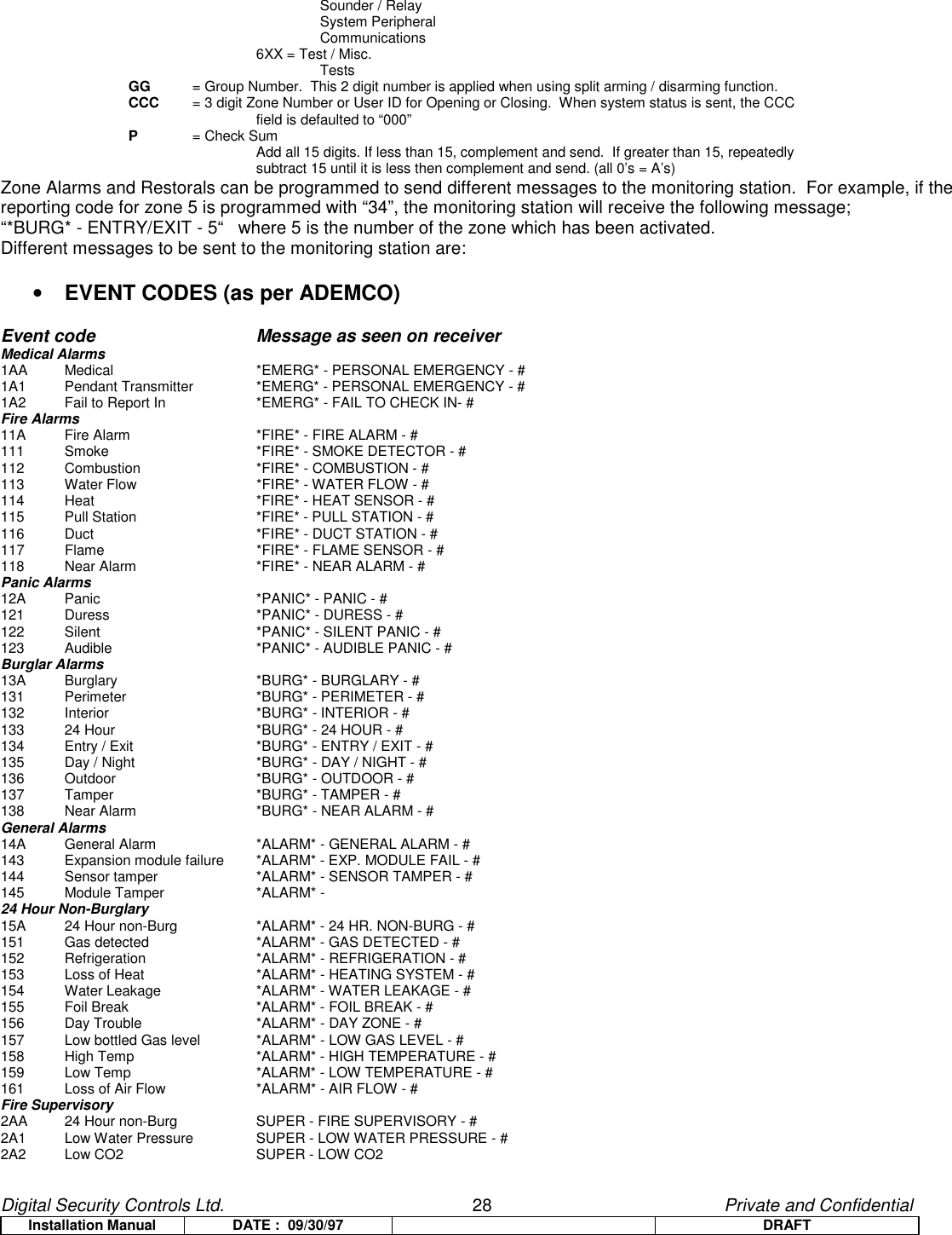
![Digital Security Controls Ltd. 23 Private and ConfidentialInstallation Manual DATE : 09/30/97 DRAFTbe supervised via the panel’s EOL supervision, and will operate according to the zone type programmed. If a zone isdisabled, it will not be supervised and all activity on the zone will be ignored by the panel.8.2.9 Telephone Numbers[301] First Telephone Number[302] Second Telephone Number[303] Third Telephone NumberAll telephone numbers are 32 digits in length.Hexadecimal digits may be programmed in the telephone number to perform certain functions.Enter [*2*] - HEX B to dial “*”Enter [*3*] - HEX C to dial “#”Enter [*4*] - HEX D for an additional dial tone search, as is required for PBX telephone systems.Enter [*5*] - HEX E to insert a 2 Second Pause in the telephone number.Notes: -There is a static delay of 2 seconds before any additional dialtone search in a phone number.-HEX A is not used; HEX F represents the end of the Phone Number (everything after F is ignored)-In order to comply with European PTT specification requirements, the panel will not attempt tocommunicate, if no phone number is programmed. This applies to Phone Numbers 1 and 2.[310] Telephone Number 1/3 Account CodeThis is the Account Code used by the panel when communicating via Phone Numbers 1 and 3.[311] Telephone Number 2 Account CodeThis is the Account Code used by the panel when communicating via Phone Number 2.Note: Both Account Codes are 4 digits in length. Valid entries are 0000-FFFE.8.2.10 Reporting CodesZone Alarms & Alarm RestoralsThese reporting codes are used by the communicator to transmit zone alarms and restorals for zones 1 to 32.These reporting codes are sent to the Alarm & Restoral call direction group.Duress AlarmThis reporting code will be transmitted to the monitoring station whenever either Duress code is used to perform any function on the system.This reporting code is sent to the Alarm & Restoral call direction group.Opening After AlarmIf programmed, this reporting code will be transmitted to the monitoring station on Opening if an alarm occurred during the previous armed period. This reporting code is sent to the Alarm & Restoral call direction group of the System.Recent Closing](https://usermanual.wiki/Tyco-Safety-Canada/99SS9001/User-Guide-68638-Page-23.png)
![Digital Security Controls Ltd. 24 Private and ConfidentialInstallation Manual DATE : 09/30/97 DRAFTA Recent Closing transmission shall be sent if an alarm occurs within 2 minutes of an exit time expiration. The Recent Closing report will be sent for the first alarm only.This reporting code is sent to the Alarm & Restoral call direction group of the System.[F], [A], [P] Alarms & RestoralsIf enabled, these reporting codes will be sent if the keys are used to generate manual alarms.These reporting codes are sent to the Alarm & Restoral call direction group of Partition 1.Zone Tampers & Tamper RestoralsThese reporting codes are used by the communicator to transmit zone tampers and restorals for zones 1 to 32.These reporting codes are sent to the system Tamper Alarm & Tamper Restoral call direction group of the System.Keypad LockoutThis reporting code is sent whenever the System enters Keypad Lockout.This reporting code is sent to the system Tamper Alarm & Tamper Restoral call direction group of the System.Closing by Users 1-32, 40, 41, 42A closing by any of these access codes will result in transmission of the corresponding reporting code.These reporting codes are sent to the Opening and Closing call direction group of the System. Thissoftware version will log either “Armed in Stay Mode” or “Armed in Away Mode” for this closing type.Closing by Users 33 & 34 (Duress)Similarly, a closing by these access codes will result in transmission of the corresponding reporting code.These reporting codes are sent to the Opening and Closing call direction group of the System.See also Duress Alarm Reporting Code.Partial ClosingIf programmed, this reporting code will be transmitted to the Central Station with the Closing code if there were zones manually bypassed at the time of arming to warn of a security compromise. Automatic bypasses caused by Stay Arming will not cause this code to be transmitted. Zones force armed by Automatic Arming will transmit in the manner described above. If SIA is used, each zone will be identified using the UB-XX (Untyped Bypass) identifier. The identified zones will follow the partial closing code and precede the closing transmission.Special ClosingIf the system is closed (armed) using any of the following methods, this reporting code will be transmitted.Maintenance Code, Keyswitch Zone, Downloading, Quick Arm (*0), Auto Arming. This software versionwill also log either “Armed in Stay Mode” or “Armed in Away Mode” for all closing types.Opening by Users 1-32, 40, 41, 42An opening by any of these access codes will result in transmission of the corresponding reporting code.These reporting codes are sent to the Opening and Closing call direction group of the System.Opening by Users 33 & 34 (Duress)Similarly, an opening by these access codes will result in transmission of the corresponding reporting code.These reporting codes are sent to the Opening and Closing call direction group of the System.See also Duress Alarm Reporting Code.Auto Arm Cancellation](https://usermanual.wiki/Tyco-Safety-Canada/99SS9001/User-Guide-68638-Page-24.png)
![Digital Security Controls Ltd. 26 Private and ConfidentialInstallation Manual DATE : 09/30/97 DRAFTwireless zone. These reporting codes are sent to the System Maintenance Call Direction Group.Periodic Test TransmissionWhen the programmed interval and time of day have elapsed, this reporting code will be transmitted to the central monitoring station. This reporting code is sent to the System Test Transmission Call Direction Group.System TestWhen the [*][6][Master Code][4] command is used to perform a manual system test, this reporting code is sent to test the communicator. This reporting code is sent to the System Test Transmission Call Direction Group.Wireless Maintenance Reporting CodesThe following reporting codes are sent to report a Low Battery condition on the system. Individual zones are not described using the Pulse formats however the individual zones will be logged to the event buffer. SIA and Contact I.D. formats will identify the zone with the condition.General Zone Low Battery Alarm and Restore CodesA low battery alarm occurs when the system component’s battery voltage supply drops below 3.3 (3.5) Volts. A zone trouble will be displayed immediately but the transmission may be delayed (see Section [370]). A low battery restoral may only take place after the alarm sensing device has been tampered and the batteries have been changed. These reporting codes are transmitted to the System Maintenance Call Direction group.8.2.11 Communicator Format Options [360]This section requires 2 two digit entries (1 per phone number). The 3rd telephone number uses the format programmed forthe 1st telephone number.01 20 BPS, 1400 HZ handshake02 20 BPS, 2300 HZ handshake03 CONTACT I.D.04 SIA FSK05 PagerREPORTING CODESSIA - 0 is valid in Account or Rep Code (not 00 in a Reporting code though)ADEMCO Contact ID - 0 is not valid in Account or Rep Code (A must be used, 10 in checksum)BPS Formats - 0 is not valid in Account or Rep Code (A must be used)SIAThis format uses 300 Baud FSK as the communication media.The Account Codes must be 4 hexidecimal digits in length all reporting codes must be 2 digits in length.The SIA format will transmit a 4 digit account code, a 2 digit identifier code and a 2 digit reporting code.The 2 digit identifier is preprogrammed by the panel.Reporting CodesFor the programmable reporting codes, if the reporting code contains the data FF, the communicator will automatically construct the default reporting code to be sent for the SIA format (please see Appendix A). If thereporting code contains the data 00, the event is disabled and not transmitted. If the reporting code contains anyother data between 01 and FE, this is sent as the reporting code (also see option SIA Transmits Automatic orProgrammed Reporting codes).Appendix A has all identifiers and the automatically constructed reporting codes.Note: XX represents the Zone/User Number.00 represents a System Event which is not specific to a zone or user number.](https://usermanual.wiki/Tyco-Safety-Canada/99SS9001/User-Guide-68638-Page-26.png)
![Digital Security Controls Ltd. 27 Private and ConfidentialInstallation Manual DATE : 09/30/97 DRAFTLevel 2 (Hardcoded)The SIA communication format used in this product follows the Level 2 specifications of the latest SIA Digital CommunicationStandard – July 1997 (Draft Only). This format will send the Partition 1 Identifier (Account Code) along with a PartitionIdentifier (1 or 2) in its data transmission. At the receiver, the transmission would look like .........N Ri01/BA 01XX XXEtc.N = New EventRi01 = System Area (or Partition One on partitioned panels)BA = Burglary Alarm01 = Zone 1XX = Next event from the same area in the same transmission.CONTACT I.D.The Account Codes must be 4 decimal digits in length all reporting codes must be 2 digits in length.This format uses DTMF touch tone as the communication media. It requires a Dual-Tone initial handshake (1400/2300) andafter sending the message, it requires a 1400 Hz kissoff.This software has a built in Automatic Contact I.D. reporting Code table similar to SIA. This table may be found in its entiretyin Appendix C. An option exists that determines whether or not the Contact I.D. format will transmit Automatic orProgrammed reporting codes (please see Section [381] Option 7).Contact I.D. behaves similarly to SIA with respect to reporting codes; if [00] is programmed for any event, it will notcommunicate. If [FF] is programmed the automatic reporting code will be transmitted (if programmed). If the “Contact I.D.Sends Programmed Codes” option is enabled, the panel will not send anything for the event as valid entries are [01]-[FE].Please see both Appendices B and C for a total list of both suggested and automatic Contact I.D. reporting codes.Note: The Australian Automatic Contact I.D. is different than that of the Standard Product. Please see Appendix C fordifferences.The format is: AAAA 18 Q XXX GG CCC PWhere: AAAA = 4 digit Account Code18 = Unique format identifier (not programmed, displayed, or printed)Q= Qualifier, which gives specific event information1 = New Event or Opening3 = New Restore or Closing6 = Previously reported off normal eventXXX = Event CodeNote: XX represents the Reporting Code programmed by Installer 1XX = AlarmsMedicalPanicBurglaryGeneral24 Hour2XX = SupervisoriesFire3XX = TroublesSystemSounder / RelaySystem PeripheralCommunicationsProtective LoopSensor4XX = Open / Close GroupOpen / CloseRemote AccessAccess Control5XX = Disables / BypassesSystem](https://usermanual.wiki/Tyco-Safety-Canada/99SS9001/User-Guide-68638-Page-27.png)
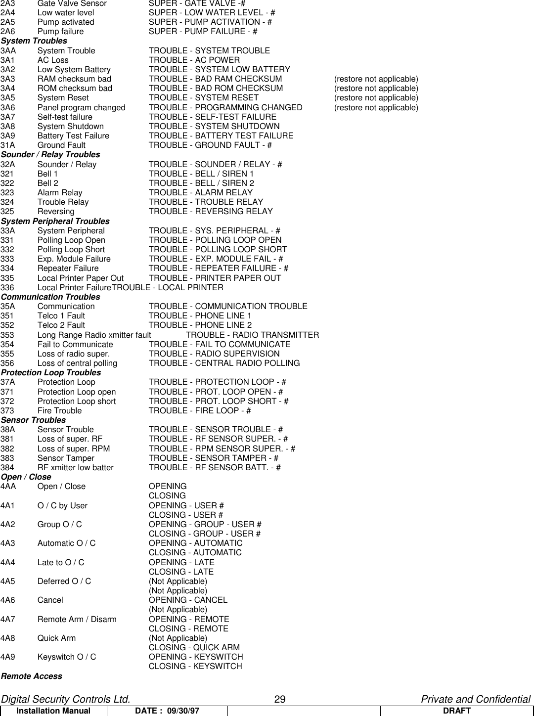
![Digital Security Controls Ltd. 30 Private and ConfidentialInstallation Manual DATE : 09/30/97 DRAFT411 Callback request made REMOTE - CALLBACK REQUESTED (restore not applicable)412 Successful Download access REMOTE - SUCCESSFUL ACCESS (restore not applicable)413 Unsuccessful access REMOTE - UNSUCCESSFUL ACCESS (restore not applicable)414 System Shutdown REMOTE - SYSTEM SHUTDOWN415 Dialer Shutdown REMOTE - DIALER SHUTDOWNAccess Control421 Access denied ACCESS - ACCESS DENIED - USER #422 Access report by user ACCESS - ACCESS GAINED - USER #System Disables5AA-51ASounder / Relay Disables52A Sounder / Relay disable DISABLE - SOUNDER / RELAY #521 Bell 1 disable DISABLE - BELL / SIREN 1522 Bell 2 disable DISABLE - BELL / SIREN 2523 Alarm relay disable DISABLE - ALARM RELAY524 Trouble relay disable DISABLE - TROUBLE RELAY525 Reversing relay disable DISABLE - REVERSING RELAYSystem Peripheral Disables53A-54ACommunication Disables551 Dialer disabled DISABLE - DIALER DISABLE552 Radio xmitter disabled DISABLE - RADIO DISABLEBypasses57A Zone bypass BYPASS - ZONE BYPASS - #571 Fire bypass BYPASS - FIRE BYPASS - #572 24 Hour zone bypass BYPASS - 24 HOUR BYPASS - #573 Burg bypass BYPASS - BURG. BYPASS - #574 Group bypass BYPASS - GROUP BYPASSTest / Misc.6A1 Manual Trigger TestTEST - MANUALLY TRIGGERED (restore not applicable)6A2 Periodic Test report TEST - PERIODIC (restore not applicable)6A3 Periodic RF xmission TEST - PERIODIC RADIO (restore not applicable)6A4 Fire test TEST - FIRE TEST (restore not applicable)6A5 Status report to follow TEST - STATUS FOLLOWS (restore not applicable)6A6 Listen-in to follow TEST - LISTEN-IN ACTIVE (restore not applicable)6A7 Walk test mode TEST - WALK TEST MODEPagerPager format uses SurGard 4/3 DTMF timing parameters.It sends the Account Code, reporting code and a [#] (Hex “C”) 1 time only.There is no checksum, parity or handshake.This communication format cannot be used for Backup or Alternate dialing (Phone Number 3).Communication of this format shall not generate or clear any FTC conditions.Note: If an Automatic Communications format is used for any other phone number, the desired reporting code to betransmitted via Pager must be programmed for the event!8.2.12 Communicator Call Directions [361]-[368]For events from each Call Direction group the control panel can call 2 different phone numbers and use the LINKS as backupor as a redundant communicator for one or both numbers. The Third phone number can only be used as a backup oralternate of the first.Each report falls under one of the following 5 Groups:System Alarms & RestoralsSystem Openings & ClosingsSystem Tampers & RestoralsSystem Maintenance Alarms & RestoralsSystem Test TransmissionsEach group can be assigned to the following Call DirectionsOption 1 1st Telephone Number (and 3rd Telephone Number if enabled for Alternate or Backup)Option 2 2nd Telephone Number](https://usermanual.wiki/Tyco-Safety-Canada/99SS9001/User-Guide-68638-Page-30.png)
![Digital Security Controls Ltd. 31 Private and ConfidentialInstallation Manual DATE : 09/30/97 DRAFT8.2.13 Communication Variables [370]Swinger Shutdown (Alarms & Restorals)This value defines the number of attempts (alarm and restoral pairs) per zone that the communicator will make before it shuts down for that zone (“swinger shutdown”). Program a 3 digit number from 000 to 014. When programmed as 000, the communicator will not be shut down and all alarms will be transmitted.Note: The Bell and Event Buffer can follow Swinger Shutdown if enabled.Swinger Shutdown (Tampers & Restorals)This value defines the number of times the same system Tamper type event will occur before stopping transmissions.Swinger Shutdown (Maintenance Troubles & Restorals)This value defines the number of times the same system Maintenance (Trouble) type event will occur before stopping transmissions.Notes: Fire Troubles will follow the Maintenance Swinger Shutdown Variable.Communication Delay (seconds)This value defines the delay before transmission. The delay is for zones which have the Transmission Delay attribute enabled. Program a time from 000 to 255 seconds.AC Failure Communication Delay (minutes)This value determines the delay before an AC FAILURE or AC RESTORE is reported. The AC failure or restoral is still displayed immediately. Program a time from 000 to 255 minutes.TLM Trouble DelayThe number of valid checks (10 second interval) required before a Telephone Line trouble is generated is programmed here. Valid entries are 000-255 for trouble annunciation and transmission (LINKS) delays of 10 to 2550 Seconds (42.5 Minutes).Test Transmission Cycle (Land-line)This value determines the period between Test Transmissions for the Land Line. Valid entries are [000]-[255]. Whether this interval is in minutes or days is determined on Section [702], Option 3.Wireless Zone Low Battery Transmission Delay (in days)When a zone reports a low battery condition, the trouble condition will be indicated immediately on thekeypad, but the transmission to the monitoring station will be delayed by the number of days programmed inthis section. If the user does not correct the low battery condition before the delay expires,the low battery condition will be transmitted.The Low battery alarm and restoral codes will only be reported once per armed period.The Low Battery Restore transmission is not delayed.Delinquency Transmission DelayThe value in this section determines the period of time that the Delinquency Event will be postponed until itlogged to the Event Buffer and transmitted. Whether this value is in hours or days is determined ifDelinquency is for Activity (hours) or Closing (days) as specified in Section [380] Option 8.[371] Test Transmission Time of DayProgram the time of the test transmission in this section. Enter a 4-digit time using the 24 hour clock format (HH:MM). Validentries are from 00 to 23 for the hours (HH) and 00 to 59 for the minutes (MM).To disable the test transmission, enter [9999] in this section.](https://usermanual.wiki/Tyco-Safety-Canada/99SS9001/User-Guide-68638-Page-31.png)
![Digital Security Controls Ltd. 32 Private and ConfidentialInstallation Manual DATE : 09/30/97 DRAFT8.2.14 Communicator Option Codes[380] First Communicator Options Code[1] Communications OptionsON = Communicator Enabled.The system’s communicator will be enabled and all events with reporting codes will be reported tothe monitoring station. Refer to the Telephone Number, Reporting Code and Call DirectionProgramming Sections.OFF = Communicator Disabled.The system’s communicator will be shut off and events will not be transmitted to the monitoringstation. Downloading may still be performed if enabled.[2] Restoral Transmission OptionsON = Restoral Transmissions on Bell-Time-out.Zone restoral reporting codes will not be transmitted until the zone has been restored and the Bellcut-off time has expired. If the zone is not restored when the bell cut-off time expires, the restoralwill be transmitted when the zone physically restores or when the system is disarmed. Note that 24Hour zones will not restore until the zone is physically restored.OFF = Restoral Transmissions Follow Zones.Zone restoral reporting codes will be transmitted when the zone is physically restored. If thezones are still active when the system is disarmed, the restoral codes will be transmitted when thesystem is disarmed. Note that 24 Hour zones will not restore until the zone is physically restored.[3] Dialing Format OptionsON = Pulse Dialing.The WLS9000 will dial telephone numbers using pulse (rotary) dialing.OFF = DTMF Dialing.The WLS9000 will dial telephone numbers using DTMF (dual tone multi-frequency) dialing.[4] DTMF Crossover OptionsON = Switch to Pulse Dialing after 4 DTMF attempts.If DTMF dialing is enabled, the WLS9000 will dial telephone numbers using DTMF dialing forthe first 4 attempts. If unsuccessful, the system will switch to pulse (rotary) dialing for the final 4attempts.OFF = DTMF Dial for all Attempts.If DTMF dialing is enabled, the WLS9000 will dial telephone numbers using DTMF dialing for alldialing attempts.[5] 3rd Phone Number Enabled / DisableON = 3rd Phone Number Enabled.The 3rd Phone number will be used for Alternate Dialing with the 1st Phone Number or as a Backupof the 1st Phone Number (see light 6).OFF = 3rd Phone Number Disabled.The 3rd Phone number will not be used.[6] 3rd Phone Number OptionsON = Alternate Dialing Enabled (1st & 3rd).After each dialing attempt, the communicator switches between the 1st Phone Number and 3rdPhone Number until 8 attempts have been made to each number.OFF = Call 1st Number, Backup to 3rd Number.If 8 attempts to communicate to the First Telephone Number fail, up to 8 attempts will be made tocommunicate to the Third Telephone Number. If all 8 attempts to communicate to the ThirdTelephone Number fail, a Failure to Communicate Trouble will be generated.](https://usermanual.wiki/Tyco-Safety-Canada/99SS9001/User-Guide-68638-Page-32.png)
![Digital Security Controls Ltd. 33 Private and ConfidentialInstallation Manual DATE : 09/30/97 DRAFT[7] Not Used[8] Delinquency OptionsON = Delinquency Follows Zone Activity (Activity Delinquency).This feature assists in the monitoring of the elderly and the handicapped. If there is no zone activityon the system, the Delinquency Transmission Delay timer in Section [370] will begin counting inhours. When the counter reaches the programmed time, the panel will communicate theDelinquency Code to the central station, if programmed. If there is zone activity present on thesystem at any time, the counter will be reset. If this option is used, the Closing Delinquency option isnot available.Notes: This code will not be transmitted for panels that are “Away” armed.Activity on Bypassed zones does not affect this timer.This timer is also reset upon arming.OFF = Delinquency Follows Arming (Closing Delinquency).This reporting code is sent whenever the programmed number of days for Delinquency hasexpired without the panel being Armed. The timer for this feature is programmed in Section [370].This value programmed in this section determines the number of days the panel counts when notbeing armed before sending the Delinquency reporting code to the central station. Once this code issent, the timer will not be started again until the panel has been armed. Each day programmed inthe counter represents one day PLUS the time it takes for the panel to reach midnight. This featuremay disabled by programming 000 in Section [370].[381] Second Communicator Options Code[1] Opening After Alarm Keypad Ringback Options ON = Opening After Alarm Keypad Ringback Enabled.When the Opening After Alarm reporting code is successfully transmitted to a programmedtelephone number, the keypad will sound a series of 8 beeps to confirm to the end user that theOpening After Alarm Code was sent and received. This Ringback will occur for each Opening AfterAlarm code successfully reported.OFF = Opening After Alarm Keypad Ringback Disabled[2] Opening After Alarm Bell Ringback OptionsON = Opening After Alarm Bell Ringback Enabled.When the Opening After Alarm reporting code is successfully transmitted to a programmedtelephone number, the Bell will sound a series of 8 squawks to confirm to the end user that theOpening After Alarm Code was sent and received. This Ringback will occur for each Opening AfterAlarm code successfully transmitted.OFF = Opening After Alarm Bell Ringback Disabled[3] SIA Reporting Code OptionsThis option is for use with the SIA communication format.). If 00 is programmed in the reporting code section, the event will not be communicated.ON = SIA Sends Programmed Rep. Codes.When this option is ON and there is a valid reporting code programmed in the reporting codesection, the programmed reporting code will be transmitted.If FF is programmed as a reporting code, the event will not be communicated.OFF = SIA Sends Automatic Rep. Codes.When this option is OFF and there is a valid reporting code (01-FE) or FF programmed in thereporting code section, the panel will transmit an automatic reporting code for SIA only. This wouldbe used when automatic reporting codes are required but there is a requirement for a differentreporting code (ie Pager Format, etc).Reporting Code Entry Option ON Option OFF](https://usermanual.wiki/Tyco-Safety-Canada/99SS9001/User-Guide-68638-Page-33.png)
![Digital Security Controls Ltd. 34 Private and ConfidentialInstallation Manual DATE : 09/30/97 DRAFT00 No Transmission No TransmissionFF No Transmission Auto Rep Code sent01-FE 01-FE sent Auto Rep Code sent[4] Closing Confirmation OptionsON = Closing Confirmation Enabled.When a Closing reporting code is successfully transmitted to a programmed telephone number, thekeypad will sound a series of 8 beeps to confirm to the end user that the Closing Code was sent andreceived.OFF = Closing Confirmation Disabled.There will be no keypad ringback when a Closing reporting code is successfully transmitted to aprogrammed telephone number.[5] Talk/Listen Options for Phone Number One/ThreeON = Talk/Listen (PC5928) on Phone #1/3 Enabled.If Talk/Listen is requested for an event by the PC5928, the panel will request the session on thenext communication on Phone Number 1/3 (via L-Block) to the central station.OFF = Talk/Listen (PC5928) on Phone #1/3 Disabled.The panel will not request a Talk/Listen session for an event even if the PC5928 has requested it.[6] Talk/Listen Options for Phone Number TwoON = Talk/Listen (PC5928) on Phone #2 Enabled.If Talk/Listen is requested for an event by the PC5928, the panel will request the session on thenext communication on Phone Number 2 (via L-Block) to the central station.OFF = Talk/Listen (PC5928) on Phone #2 Disabled.The panel will not request a Talk/Listen session for an event even if the PC5928 has requested it.[7] Contact I.D. OptionsON = Contact I.D. Uses Programmed Reporting Codes.The Contact I.D. communications format will use programmed reporting codes when transmittingto central station.OFF = Contact I.D. Uses Automatic Reporting Codes.The Contact I.D. communications format will use the automatic reporting codes as shown inAppendix C when transmitting to central station.Note: The Australian Automatic Contact I.D. is different than that of the Standard Product. Pleasesee Appendix C for differences.[8] For Future Use.8.2.15 Downloading Options[401] First Downloading Option Code[1] Downloading Answer OptionsON = Downloading Answer Enabled.The system will answer calls for downloading if a successful Double call routine is detected. Havethe downloading computer call the system and let the telephone line ring once or twice. After 1 or 2rings, hang up. If called back within the programmed Double Call Time (000-255 seconds), thepanel will answer on the first ring.OFF = Downloading Answer Disabled.The system will not answer incoming calls using the Double Call routine unless the User enables theDLS window. This option can be enabled by turning Option 2 ON.[2] DLS Window OptionsON = User Can Enable DLS Window.](https://usermanual.wiki/Tyco-Safety-Canada/99SS9001/User-Guide-68638-Page-34.png)
![Digital Security Controls Ltd. 35 Private and ConfidentialInstallation Manual DATE : 09/30/97 DRAFTThe user can use the [*][6][Master Code][6] Command to enable a 6 hour window in which the panelwill answer calls for downloading if a successful Double Call routine is detected. If this option isenabled, the window is open upon power up. The window is on for the full 6 hours if enabled.OFF = User Can Not Enable DLS Window.The user can not enable a window for DLS calls.Note: Options 1 and 2 are not related. One does not need to be enabled for the other to perform its function.[3] Call-Back OptionsON = Call-Back Enabled.When the system answers the downloading computer’s call, both the computer and the WLS9000will hang up. The panel will then call the Downloading Telephone Number and connect with thecomputer at that number. If more than one downloading computer is to be used, this function shouldbe disabled.OFF = Call-Back Disabled.The downloading computer will have immediate access to the WLS9000 once it is identified as avalid system.[5] Auto Event Buffer UploadON = Auto Event Buffer Upload Enabled.After the panel has communicated the “Event Buffer 75% Full” event to central station, the panelwill call the Downloading Computer’s telephone number. DLS software will then perform an eventbuffer upload upon successful connection.OFF = Auto Event Buffer Upload Disabled.After the panel has communicated the “Event Buffer 75% Full” event to central station, the panelwill not call the Downloading Computer’s telephone number.[6]-[8] For Future Use[402] Downloading Computer’s Telephone NumberThis telephone number is 32 digits in length.[403] Downloading Access CodeThis 4-digit Hexadecimal code allows the panel to confirm that it is communicating with a valid downloading computer.[404] Panel Identification CodeThis 4-digit Hexadecimal code allows the downloading computer to confirm the identity of the control panel.[405] Double-Call TimerThis timer sets the amount of time that can be taken between calls when using Double Call to contact the WLS9000.Valid entries are 001 to 255 (seconds)[406] Number of Rings to Answer OnThe value in this section determines how many rings that the WLS9000 will automatically pick up on in order toestablish a DLS connection. Default value is 000 rings. Valid entries are [000]-[020].NOTE: If both Section [401] Option 1 and Section [406] are enabled, either one will work depending onhow the installer calls the premises.](https://usermanual.wiki/Tyco-Safety-Canada/99SS9001/User-Guide-68638-Page-35.png)
![Digital Security Controls Ltd. 36 Private and ConfidentialInstallation Manual DATE : 09/30/97 DRAFT8.2.16 International Programming Sections[700] Automatic Clock AdjustIn order to compensate for Crystal/Ceramic Resonator inaccuracies, Software has implemented a solution. Thevalue here is designed to add or subtract seconds at the end of each day. Valid entries are 00-99 with 60 secondsbeing the default minute. To determine the value to be programmed in this section, the installer will need to monitorthe time lost by the panel over a length of time. The installer will then be required to calculate the average amount oftime per day that the panel gains or loses. Once the installer has this value, it may be compensated for through thisfeature.Example: Panel loses an average of 9 seconds a day.Instead of loading 60 seconds for the last minute of each day, program the panel to load 51seconds with the use of Section [700]; this will speed up the panel by 9 seconds everyday,thereby fixing the problem.[701] First International Options Code[1] AC OptionsON = 50 Hz AC.The incoming AC power cycles at 50 Hz.OFF = 60 Hz AC.This is the North American standard where the incoming AC power cycles at 60 Hz.[2] Time Base OptionsON = The timebase is the internal crystal oscillator.In cases of unstable AC power input, the internal crystal can be used to keep the most accuratetimebase.OFF = The timebase is the AC power input.The 50 or 60 Hz AC power input is normally very stable and can be used as the timebase.[3] Arming Inhibit OptionsON = AC/DC Arming Inhibit with Battery Check Enabled.When an AC or DC trouble is present, the system will not arm. This includes Keypad, Keyswitch,Automatic, and Downloading Arming. If enabled and arming is attempted, the system will perform aSystem Battery check as well as a Battery Check on all peripheral modules supported by a backupbattery.OFF = Arming not Inhibited.The system can be armed, regardless of the presence of an AC or DC trouble and will not checkall system batteries upon arming.NOTE: If this option is enabled, it is strongly recommended that AC Troubles be displayed (Section [017], Option 1 ON).[4] Latching System Tamper OptionsON = System Tampers Require Installer Reset and Inhibit Arming.If any system tamper condition occurs, the Installer’s code must be entered [*][8][Installer Code] andthe tamper condition must be restored before the system can be armed. This also includes AutoArming and Keyswitch. If Auto Arming is attempted with a latched tamper, the panel will not arm.The Auto Arm Cancellation code is not transmitted however because a user did not cancel the AutoArming sequence.Note: If enabled, the manual bypassing of a zone will not bypass the tamper or fault states(DEOL).OFF = System Tampers Do Not Require Installer Reset.[5] Access Code Length OptionsON = 6-digit Access Codes.](https://usermanual.wiki/Tyco-Safety-Canada/99SS9001/User-Guide-68638-Page-36.png)
![Digital Security Controls Ltd. 37 Private and ConfidentialInstallation Manual DATE : 09/30/97 DRAFTAll access codes on the system will be 6 digits in length except the Panel I.D. Code and theDownloading Access Code. If this option is selected, the last digit of each code will no longer beused, the codes will remain programmed.System Master Code = XXXX56 XXXX = previous code, (1234)Installer Code = YYYY00 YYYY = previous code, (5010)OFF = 4-digit Access Codes.All access codes on the system will be 4 digits in length. For any existing codes, the last 2 digits areremoved.[6] Busy Tone OptionsON = Busy Tone Detection Enabled.If these tones are detected, the communicator will disengage the phone line and try to place the callagain following the “Delay Between Dialing Attempts”.OFF = Busy Tone Detection Disabled.The communicator will use the standard dialing procedure for every attempt.[7] Battery Current Charge OptionsON = High Current Battery ChargeThe panel will charge the battery at a higher current rate than the DSC standard (approx 650-700mA).. This support was added in the BlueLite ASIC.OFF = Standard Current Battery ChargeThe panel will charge the battery at the DSC standard rate of approximately 350 mA.[8] For Future Use[702] Second International Options Code[1] Pulse Dial OptionsON = Pulse Dialing Make/Break Ratio is 33/67OFF = Pulse Dialing Make/Break Ratio is 40/60[2] Force Dial OptionsON = Force Dialing Enabled.If the first attempt by the panel to call the monitoring station fails, on every subsequent attempt thepanel will dial regardless of the presence of dialtone.Note: The panel will go off-hook, search for dialtone for 5 seconds, hang-up for 20 seconds, go off-hook, search for dialtone for 5 seconds, then dial (assuming no presence of dialtone).OFF = Force Dialing Disabled.The panel will not dial the programmed telephone number if dialtone is not present.[3] Land Line Test Transmission OptionsON = Land Line Test Transmission Interval is in Minutes.The value programmed in Section [370] Seventh entry is in Minutes.OFF = Land Line Test Transmission Interval is in Days.The value programmed in Section [370] Seventh entry is in Days.[4] Handshake OptionsON = 1600 Hz Handshake.The communicator responds to a 1600 Hz handshake for BPS formats.OFF = Standard Handshake.The communicator responds to the handshake designated by the format selected (1400 or 2300Hz).[5] I.D. Tone OptionsON = I.D. Tone Enabled.After the telephone number is dialed, the panel will emit a tone (as specified by Option 6) for 500](https://usermanual.wiki/Tyco-Safety-Canada/99SS9001/User-Guide-68638-Page-37.png)
![Digital Security Controls Ltd. 38 Private and ConfidentialInstallation Manual DATE : 09/30/97 DRAFTms every two seconds to indicate that it is a digital equipment call, not voice.OFF = I.D. Tone Disabled.[6] I.D. Tone FrequencyON = 2100 Hz I.D. ToneOFF = 1300 Hz I.D. Tone[7] DLS Window OptionsON = One Time 1-hour user Enabled DLS Window.The User Enabled DLS Window is 1 hour in length and will be closed after a successful hang-upfrom a downloading call.OFF = Full 6-hour User Enabled DLS Window.The User Enabled DLS Window is 6 hours in length and remains open after a successful hang-upfrom a downloading call.Note: this option also determines the length of the DLS window available on power up.[8] FTC Bell OptionsON = Bell on FTC when armed.If a Failure to Communicate Trouble is generated while EITHER Partition is armed, the Bell outputwill sound for the length of Bell time-out or until the system is disarmed.OFF = FTC Trouble only when armed.If a Failure to Communicate Trouble is generated while the panel is armed, the Bell output will notsound but the keypad buzzer will sound trouble beeps until a key is pressed.[703] Delay Between Dialing AttemptsFor standard (force) dialing, the panel will go off-hook, search for dialtone for 5 seconds, hang-up for 20 seconds, gooff-hook, search for dialtone for 5 seconds, then dial. If there is no initial handshake recognized within 40 seconds,the panel will hang up. This programmable timer adds a delay before the next call is attempted.[704] Dialtone Search Time This is the maximum amount of time the panel searches for dial tone.Valid Entries are 001-255 seconds. Default is 005[705] Dialtone DurationThis is the minimum amount of tone required before the panel qualifies it as dialtone.Valid entries are 004-255 (x25 milliseconds). Default is 004.[706] Lower Dialtone CutoffThis is the lower dialtone cutoff frequency.Valid entries are 050-250. Default is 250.Notes: The value entered does not correspond to the frequency value. A table is required (value X = frequency Y)This value MUST be greater than that programmed in Section [707].[707] Upper Dialtone CutoffThis is the upper dialtone cutoff frequency.Valid entries are 050-250. Default is 062.NOTE: The value entered does not correspond to the frequency value. A table is required (value X = frequency Y)This value MUST be less than that programmed in Section [706].[708] Delay Between Force Dialing AttemptsThis is the time the panel waits between the first dialing attempt and the force dialattempt. Valid Entries are 001-255 seconds. Default is 020.[709] Busy Tone Duration](https://usermanual.wiki/Tyco-Safety-Canada/99SS9001/User-Guide-68638-Page-38.png)
![Digital Security Controls Ltd. 39 Private and ConfidentialInstallation Manual DATE : 09/30/97 DRAFTThis the minimum amount of tone required before the panel qualifies it as busy tone.Valid entries are 004-255 (x25 milliseconds). Default is 026.Note: Sections [704] to [709] will NOT be documented. Any changes required to theseparameters will be handled by ATE and/or Technical Support. All values programmed[807] ESCORT Programming[000] Function Key ProgrammingxivThis section is used to program the Function Keys of the WLS9000. Upon entering this section, a 1 digit entry from1 to 8 is required to select the function key to be programmed:[0] Not Used[1] Function Key 1 Assignment[2] Function Key 2 Assignment[3] Function Key 3 Assignment[4] Function Key 4 Assignment[5] Function Key 5 Assignment[6] Function Key 6 Assignment[7] Function Key 7 Assignment[8] Function Key 8 AssignmentUpon selecting [1-8], a 2 digit entry is required to assign a function to the key (F1-F8)After 2 digits are entered, the system will return to the previous section (in Section [000]).Function KeysBelow are the options available for the Function Keys. If enabled, the function key must be held for 2 seconds in order to perform the described function.00 Null Key (Not Used)The key is not used and will not perform any function when pressed.01 Not Used02 Not Used03 Stay ArmThe system is Armed with all Stay/Away zones auto-bypassed regardless of whether or not delay zones are tripped during the exit delay. This key only works while the system isdisarmed. The panel will log “Armed in Stay Mode” for this closing type.04 Away ArmThe system is Armed with all Stay/Away zones active regardless of whether or not delay zones are tripped during the exit delay. This key only works while the system is disarmed. The panel will log “Armed in Away Mode” for this closing type.05 [*][9] No-Entry ArmAfter pressing this key, entry of a valid access code is required. Then the system will be Armed with No Entry on Delay zones and all Stay/Away zones auto-bypassed regardless of whether or not delay zones are tripped during the exit delay.This key only works while the system is disarmed. Entry of a valid access is required following this key to perform the function.06 [*][4] Chime On / OffThis key Enables (3 beeps) and Disables (tone) just like pressing [*][4].This key will work while the system is armed or disarmed.](https://usermanual.wiki/Tyco-Safety-Canada/99SS9001/User-Guide-68638-Page-39.png)
![Digital Security Controls Ltd. 40 Private and ConfidentialInstallation Manual DATE : 09/30/97 DRAFT07 [*][6][----][4] System TestThis key will perform the System test when pressed. It is the equivalent of entering [*][6][Master Code][4]. This key only works while the system is disarmed.08 [*][1] Bypass ModePressing this key will put the keypad in the Zone Bypass mode. It is the equivalent of pressing [*][1] while disarmed. If an access code is required for bypassing (Section [016], Option 5), theuser must enter the access code before entry will be permitted. This key only works while thesystem is disarmed.09 [*][2] Trouble DisplayPressing this key will put the keypad into the Trouble display. It is the equivalent of pressing [*][2]. This key will work while the system is armed or disarmed.10 [*][3] Alarm MemoryPressing this key will put the keypad into the Alarm Memory display. It is the equivalent of pressing [*][3]. This key only works while the system is disarmed.11 [*][5] User ProgrammingPressing this key is the equivalent of entering [*][5]. An access code will be required before entry to this section is allowed to the User Programming menu. This key only works while the system is disarmed.12 [*][6] User FunctionsPressing this key is the equivalent of entering [*][6]. An access code will be required before entry to this section is allowed to the User Functions menu. This key only works while the system is disarmed.13-15 Not Used (Reserved)16 [*][0] Quick ExitPressing this button will perform the Quick Exit function (if enabled). It is the equivalent of pressing [*][0] while armed. This key only works while the system is armed.The Quick Exit feature must be enabled (Section [015], Option 3).17 [*][1] Activate Stay/Away ZonesPressing this key will remove the automatic bypass on all Stay/Away zones on the system.It is the equivalent of pressing [*][1] while armed. This key only works while the system is armed.18-26 Not Used (Reserved)27 Status (Query)Pressing this key will result in the WLS9000 annunciating its current status. The user can thenproceed to do other functions by pressing the corresponding keys on the WLS9000, or wait for theWLS9000’s audio prompting to time out.28 Volume ControlWhen this function key is pressed for two seconds, the WLS9000 will increment through the fourdifferent volume levels from lowest to highest, cycling back to the lowest after the highest volume isreached.29 Memo RecordWhen pressed, this function key will initiate recording (via the local microphone) of a message.Recording begins after the three acknowledgement tones are annunciated.30 Memo Playback](https://usermanual.wiki/Tyco-Safety-Canada/99SS9001/User-Guide-68638-Page-40.png)
![Digital Security Controls Ltd. 41 Private and ConfidentialInstallation Manual DATE : 09/30/97 DRAFTWhen pressed, this function key will annunciate the recorded message. If there is no messagerecorded, an error tone will be heard.8.2.17 Special Installer Functions[901] Installer Walk Test ModeTo initiate the Walk Test Mode, enter this section, then exit Installer’s mode completely. When this mode is ON, allzones become 24 hour non-force arm-able zones that will sound the bell (steady or pulsed attribute) for 2 secondsand transmit their programmed alarm reporting codes when violated.To cancel the test mode, re-enter this section. If the user attempts to arm while in Walk Test, the WLS9000 willsound an error tone and prompt that the function is not available.Note: Alarm Memory is cleared upon entering Walk Test.[902]-[903] NOT USED[904] Module Placement TestThe Module Placement Test of the WLS9000 is quite different from previous Power-Based products as itincorporated the following changes and enhancements:• Each Detector Must pass three Consecutive Tests before being enabled on the system.• Each Detector is enabled in Section [202]-[205] only after passing the three tests mentioned above. There is noway to manually override this enrollment process.• There is only “Good” and “Bad” Placements. “Fair” has been removed; it’s former status internal to the softwareis considered a “Bad”.• The piezo will squawk once for “Good” and three times for “Bad”.• If the Placement is exited before all zones are properly enrolled, a General System Trouble is generated at thekeypad. This trouble can only be cleared by re-entering the Module Placement Test and testing the un-enrolleddevices.• Zones can be disabled via Section [202]-[205], but they cannot be enabled.When Module Placement Test is entered, the system will annunciate all of the zones which have been enrolled onthe system, but are not enabled in Sections [202]-[205]. This allows the Placement Test to be entered afteradditional devices have been enrolled on the system without the hassle or re-testing ‘placed’ zones.As each device receives three “Good” placements, it is removed from the annunciation list and it’s corresponding bitin Section [202]-[205] is toggled to enable the zone on the system.[990][Installer Code][990] Installer Lockout EnableIf enabled, the WLS9000 will give a distinctive audible indication on power up (the phone line relay will click 10 times).This feature will have no effect on a Software Default (all programming will return to the factory defaults).However, if a Hardware default is attempted while lockout is enabled, the default will not occur, and the fraudulentattempt will be logged to the event buffer.[991][Installer Code][991] Installer Lockout DisableThis disables the Installer Lockout feature described above.[992][Installer Code][992] Restore Main Controller ProgrammingWhen this section is successfully entered, all programming within the Main Controller will be returned to factory default. This does not include programming found in the Rx Slave uP (i.e. Serial Numbers) or in the ESCORT (i.e.Zone descriptions, Automation programming). Section [998] and [995] may be used to perform these functions.[995][Installer Code][995] Restore ESCORT to Factory Default Programming](https://usermanual.wiki/Tyco-Safety-Canada/99SS9001/User-Guide-68638-Page-41.png)
![Digital Security Controls Ltd. 42 Private and ConfidentialInstallation Manual DATE : 09/30/97 DRAFTWhen this section is successfully entered, all programming in the ESCORT VPM Module will be returned to the factory defaults.[996][Installer Code][996] Restore Wireless Receiver Factory Default ProgrammingWhen this section is successfully entered, all programming in the Wireless Rx Slave will be returned to the factorydefaults.[999][Installer Code][999] Restore All WLS9000 Factory Default ProgrammingxvWhen this section is successfully entered, all programming within the WLS9000 will be returned to factory default. This includes programming found in the Rx Slave uP (i.e. Serial Numbers) and in the ESCORT (i.e.Zone descriptions, Automation programming). Sections [992], [995], and [996] may be used if only some areas ofthe WLS9000 are to be defaulted (i.e. Serial Number default would use [996])..4 User “Star” Functions“QUICK ARM” COMMAND[*][0] ... When DisarmedEntering [*][0] is accepted as a valid arming code when the “Quick Arm” feature is enabled by the installer. Quickarm may be used as a convenience for regular users or when the system is to be armed by individuals who are notauthorized to disarm the system. The software will log either “Armed in Stay Mode” or “Armed in Away Mode” for thisclosing type, depending on how the premises were armed.ZONE BYPASSING[*][1] or [*][1][Access Code] ... When DisarmedA bypassed zone will not cause an alarm. If a zone is bypassed the panel may be armed (“Ready” light will be on)even if the zone is open. Use zone bypass when access is needed to part of the protected area. Also, damagedwiring or contacts on a zone may be temporarily bypassed until repairs can be made so that the panel can be armed.To bypass zones, enter [*][1]. An access code may be required in order to gain access, if enabled.Then enter the TWO digit zone number.The individual bypassed zones are not shown while armed.TROUBLE DISPLAY[*][2] ... When DisarmedThe panel continuously monitors a number of possible trouble conditions. If one of these conditions occurs, thekeypad “Trouble” indicator will light and the audible indication will sound, two short beeps every 10 seconds (exceptAC failure). When the [#] key is pressed the audible indication will stop but the trouble is not cleared. Troubleconditions are logged to the Event Buffer and most troubles can also be transmitted to the monitoring station.To view troubles, press [*] then [2]. The WLS9000 will verbally prompt you with the trouble conditions on the system.Troubles 1, 5, 6 and 7 can be expanded for more details by pressing the corresponding [1][5][6] or [7] key.Press [#] to return to the “Ready” mode. There is no Trouble memory. The Event Buffer can be uploaded to achievethis function.Annunciation of troubles is permitted while armed.TROUBLE #1 SERVICE REQUIRED1. Low BatteryThe standby Battery’s voltage is measured under load every 4 minutes and during a System Test. The limits of Alarms and Restores are determined by the Swinger Shutdown (Maintenance Troubles & Restorals) counter. Set at 3 by default, there will be 3 Low Battery Troublesand 3 Low Battery Restores before latching. The latching is reset at Midnight or upon Arming.2. Bell Circuit TroubleIf the bell circuit is overdrawn or the bell circuit is open, a keypad trouble is generated and a Bell Circuit Trouble can be reported.3. General System Trouble](https://usermanual.wiki/Tyco-Safety-Canada/99SS9001/User-Guide-68638-Page-42.png)
![Digital Security Controls Ltd. 43 Private and ConfidentialInstallation Manual DATE : 09/30/97 DRAFTAny peripheral module trouble will be indicated and communicated with a General Trouble but logged to the event buffer with a detailed description.Module Placement Test Unsuccessful4. General System TamperAny peripheral module tamper will be indicated and communicated with a General Tamper but logged to the event buffer with a detailed description.5. General System SupervisoryModule Supervisory ..... If the system loses Supervisory signals from a peripheral module, this will be indicated and communicated with a General Supervisory but logged to the event buffer with a detailed description.6-8. Not UsedNote: The WLS9000 does not prompt the individual troubles within Trouble #1. The user should call forassistance in the case of a “Service Required” trouble. Please note that the specific trouble will belogged in the Event Buffer.TROUBLE #2 AC FAILUREThere is no audible annunciation on AC power failure. The system “Trouble” light will come ON but the audible indication will not sound until there is a low battery condition. Transmission delay can be programmed for 000 to 255 minutes. If the AC Fails, the battery will be continuously checked until thepanel shuts down.TROUBLE #3 TELEPHONE LINE TROUBLEThe telephone line voltage is measured every 10 seconds. If the voltage drops below 1 to 3 volts for the number of consecutive checks programmed in Section [370] plus 3 additional checks, a Telephone Line Trouble is generated. If TLM is enabled, it must perform at least 3 checks (settings of 000 and 001 in Section [370] will result in 4 checks, setting of 002 will result in 5 checks, setting of 003 will result in 6 checks, etc) The actual display can be delayed via Installer’s Programming. This additional checkdenomination may fluctuate from board to board, as it is dependant on hardware component tolerances.The TLM Restore shall occur when the value in Section [370] is reached.TROUBLE #4 FAILURE TO COMMUNICATEIf the digital communicator is unsuccessful in communicating with any of the programmed telephone numbers, a failure to communicate trouble will be generated. If a later attempt to communicate is successful, the panel can also transmit the FTC restore reporting code and all previous unsuccessfulevents.TROUBLE #5 ZONE FAULT (Fire Zone Fault)If any zone on the system is in the Trouble state, this trouble will be generated.For hardwired zones (excluding Fire) using double end of line supervision, this is the shorted state, for RF sensors, this is a loss of Supervisory signals. If DEOL is not used, Zone Troubles can still be generated on Fire Zones (open state).If [5] is pressed in the Trouble mode, the keypad will now display all of the zones in trouble.Fire Zone Faults are identified in the Event Buffer. They log a “Fault Zone X” followed by a generic“Fire Trouble”. This has been done so that intermittent wiring problems may be tracked down via theEvent Buffer.If any zone enters this Trouble state (fault), the keypad buzzers will sound trouble beeps to annunciate thecondition.TROUBLE #6 ZONE TAMPERThis trouble is used with DEOL Zone Supervision only.If any zone is in the Tamper state (Hardwired or RF), this trouble will be generated. Zones excluded from this are Fire and zones not supporting the DEOL configuration (LINKS answer, keyswitch).If [6] is pressed in the Trouble mode, the keypad will now display all of the tampered zones.If any zone enters this Tamper state (open), the keypad buzzers will sound trouble beeps to annunciate thecondition.](https://usermanual.wiki/Tyco-Safety-Canada/99SS9001/User-Guide-68638-Page-43.png)
![Digital Security Controls Ltd. 44 Private and ConfidentialInstallation Manual DATE : 09/30/97 DRAFTTROUBLE #7 DEVICE LOW BATTERYIf an RF Device reports a Low Battery signal to the panel, this trouble will be generated.When the user enters [*][2][7] to view troubles, the following then will occur. ...... Keypad Beeps 1 time .......... Shows Zones (lights) 1-8Press [7] ...... Keypad Beeps 2 times ........ Shows Handheld Keypads (lights) 1-4Press [7] ...... Keypad Beeps 3 times ........ Shows Wireless Keys (lights) 1-16 Press [7] ...... Return to Zones 1-8Note: an LCD keypad is required to view Wireless Key Low Batteries 9-16.TROUBLE #8 LOSS OF SYSTEM TIMEWhen the panel is powered up, the internal time of day clock needs to be set to the correct time. Thistrouble is cleared when an attempt is made to reset the internal time of day clock.ALARM MEMORY DISPLAY[*][3] ... When DisarmedPress [*] then [3] to enter the alarm memory mode. The WLS9000 will prompt the alarms by Zone Number (or labelif programmed) that are in memory.Press [#] to return to the “Ready” mode. If [#] is not pressed, the WLS9000 will time out in 30 seconds.There is no memory of previous armed states. The Event Buffer can be uploaded to achieve this function.DOOR CHIME ON / OFF COMMAND[*][4] ... When Armed/DisarmedThe Door Chime feature is used to sound a tone from the keypad whenever a zone programmed as a Chime type isactivated. When the Door Chime feature is turned ON, the WLS9000 will beep several times whenever a Chimezone is activated. This applies to both violating and restoring the zone.If the Verbal Chime Feature is enabled, whenever a zone with the Chime attribute enabled is violated, a series ofbeeps will sound and the WLS9000 will prompt:“Zone X”When the zone is restored, the WLS9000 will only sound a series of beeps similar to how Door Chime functions inour current products.If a label was programmed for the above Zone, the WLS9000 would annunciate (after the beeps):“Back Porch Window”…and so on.If this option is disabled, only the series of beeps will be heard upon the violation and restore of zones that areprogrammed to chime.To turn the feature on or off, enter [*][4]. If the feature is being turned ON, the WLS9000 will prompt “Door Chime isON”. If the feature is being turned OFF, the WLS9000 will prompt “Door Chime is OFF”.USER’S PROGRAMMING COMMAND[*][5][Master Code] ... When DisarmedThe [*][5] user’s programming command is used to access User code programming.User Code ProgrammingThe user be prompted to enter a Master or Supervisory code. This is required to gain access to the section.User Codes (Access Codes 1-32)](https://usermanual.wiki/Tyco-Safety-Canada/99SS9001/User-Guide-68638-Page-44.png)
![Digital Security Controls Ltd. 45 Private and ConfidentialInstallation Manual DATE : 09/30/97 DRAFTMaster Code (Access Code 40)The Master code can only be changed by the Master or the Installer if the code is changeable (Installer Option).Supervisor Codes (Access Codes 41 & 42)Program Codes (Blank or Lesser only). These codes are always valid when entering the [*][5] User CodeProgramming section. However, these codes can only program codes which have equal or lesser attributes.Once programmed, the Supervisor Codes receive the Master’s attributes. These attributes are changeable.Duress Codes (Access Codes 33 & 34)Duress codes 33 and 34 are standard user codes that will transmit the Duress Reporting Code whenever the code isentered to perform any function on the system.NOTE: Duress codes are not valid when entering [*][5], [*][6] or [*][8] sections.User Code AttributesNotes: 1) The default attributes of a new code will be the attributes of the code used to enter [*][5] whether it is a new code or an existing code being programmed.2) System Master (Code 40) has attributes 1-4 ON by default and they are not changeableInherent Attributes (All codes except Installer and Maintenance)Arm / Disarm - Any Access Code with (Option 1) enabled will be valid for Arming and Disarming thesystem.Bell Squawk on Arming/DisarmingAttribute 7 will be used to determine whether an access code should generate an arming/disarming BellSquawk upon entry of the code. This is so that Wireless Keys with Access Codes associated with them maygenerate Arming/Disarming Bell squawks, but a normally entered access code at a keypad will not. Ifdesired, this option may be used with codes that are manually entered. This option is defaulted off for allaccess codes.Notes: The “Bell Squawk on Arming/Disarming” option (Section [014], Option 1) overrides this feature.This feature cannot prevent the Arm/Disarming Squawks to be generated if an access codeassigned to a WLSKey is manually entered at a keypad.The Master Code cannot use the Bell Squawk attribute.Programmable Attributes1 User Enabled (Arming, Disarming, Alarm Reset, Auto Arm Cancel)2 Not Used3 Zone Bypassing enabled4-6 Reserved (Not Used)7 Bell Squawk upon Arming/Disarming8For Future UseNotes on Access Codes and Programming1) There will still be 39 codes if option selected for 6 digit access codes (see also Installers and Maintenance).[*][5][MASTER CODE] [01 to 32, 33, 34, 40, 41, 42] to program access codes[*][5][MASTER CODE][9] Enters the Attribute Mode [01 to 32, 33, 34, 41, 42] to edit access codes2) The Master Code’s attributes cannot be changed.Note: the Master Code cannot use the Bell Squawk attribute.Erasing an Access CodeTo erase a code, select the code and enter [*] as the first digit. If [*] is entered, the system willdelete the code immediately and the user will be prompted to select another code.USER’S FUNCTIONS COMMAND](https://usermanual.wiki/Tyco-Safety-Canada/99SS9001/User-Guide-68638-Page-45.png)
![Digital Security Controls Ltd. 46 Private and ConfidentialInstallation Manual DATE : 09/30/97 DRAFT[*][6][Master Code] ... When DisarmedThe [*][6] command is used to gain access to the following list of Master functions of the system.[1] Time and Date Enter 4 digits for 24 Hour System TimeEnter 2 digits each for Month, Day and Year (HH-MM-MM-DD-YY)Valid entries for the Hour are 00-23. Valid entries for the Minute are 00-59.[2] Auto-Arm Control Pressing [2] while in the User Function menu will enable (3 beeps) or disable (one long beep) the Auto-arm feature. With this feature enabled, the panel will automatically arm in the Away mode (Stay Away zones active) at the same time each day. The Auto Arm time is programmed with the [*][6][Master Code][3]command.NOTES: All arming inhibit features such as Latching Tampers, AC & DC inhibit, etc. shall also inhibit the Auto Arm and send the Auto Arm Cancellation code.Keypads are required if Auto-Arm is to be used.[3] Auto-Arm Time The system can be programmed to arm at the same time . Upon entry of this section, enter 4 digits for the 24 Hour Auto-Arm time.At the selected Auto-Arm time, the WLS9000 will sound for 1 minute to warnthat an Auto-Arm is in progress. The siren can also be programmed to squawk onceevery 10 seconds during this warning period. When the warning period is complete,the system will arm with no exit delay and Stay Away zones active (if programmed).Auto-Arming can be canceled only by entering a valid access code duringthe 1-minute warning period. When the code has been entered, the warning will besilenced and Auto-Arming will be canceled. Auto-Arming will be attempted at thesame time the next day. During the 1 minute warning period, keyswitch arming orQuick arming will cancel the Auto-Arm process and will initiate the exit delay beforearming the system. Whenever the Auto-Arming process is canceled, the Auto ArmCancellation Reporting Code will be transmitted (if programmed).If arming is inhibited by one of the following, the Auto Arm Cancellation transmission will be communicated.- AC / DC Inhibit Arm- Latching System Tampers- Zone Expander Supervisory Fault[4] System Test The system’s Bell Output (2sec), Keypad Lights and Communicator are tested.This test will also measure the panel’s standby battery.[5] Enable DLS If enabled, this will open a window where rings will be detected by the panel. Thelength and frequency of this window is dependant on the state of Option 7 in Section[701].[6] User Call-up If enabled by the Installer, when this command is executed, the panel willmake 1 attempt to call the downloading computer. The downloading computer mustbe waiting for the panel to call before downloading can be performed.[7] Volume Control The volume in which the ESCORT prompts can be controlled by entering thissection. Options are ‘Low’, ‘Medium’, ‘High’ and “Highest”, with Low as the default.Note: Better control of the WLS9000’s volume can be achieved via the VolumeFunction Key.[8] Speech Rate The rate or speech can be changed upon entry of this section. Options are ‘fast’and ‘slow’, with fast as the default.[9] Not Used[0] Not Used](https://usermanual.wiki/Tyco-Safety-Canada/99SS9001/User-Guide-68638-Page-46.png)
![Digital Security Controls Ltd. 47 Private and ConfidentialInstallation Manual DATE : 09/30/97 DRAFTINSTALLER’S PROGRAMMING COMMAND[*][8][Installer Code] ... When DisarmedThe WLS9000 is completely programmable from the Main Unit Interface using this command.As described in Section 5.2.2, a Simple Installer’s Programming Front End Interface (the Wizard) has been added tothe WLS9000. Please see Section 5.2.2 for more information.ARMING WITHOUT ENTRY DELAY[*][9][Access Code] ... When DisarmedEntering [*][9] or pressing a function key programmed for No Entry Arm before entering an access code, arms thepanel without any entry delay on the perimeter delay zones and bypasses zones that are defined as “Stay/Away”.This command is used to arm the system while at home. When the system is armed in this mode, the “Armed” lightwill be ON flashing and WLS9000 will prompt that there are zones bypassed. Once the panel is armed in this mode,using [*][1] will remove the bypass from the “Stay/Away” zones if they were NOT manually bypassed. The [*][1]command used here only removes the bypass from zones that have been automatically bypassed with the [*][9]command.Note: Delay Stay/Away and Interior Delay Zones will still have Entry Delay on a [*][9] armed panel.QUICK EXIT[*][0] ... When ArmedEntering [*][0] when the system is armed will allow the user 2 minutes to exit the premises through any delay zonewithout altering the status of the system if the quick exit feature is enabled. After [*][0] is entered, one and only onedelay zone may be tripped. If the delay zone is left unrestored at the end of the 2 minutes, it will begin its entry delaysequence. Any additional activity on any other active zone will cause that zone to begin its alarm or delay sequence.Quick Exit is not designed to extend the standard Exit Delay.ACTIVATE AUTO BYPASSED STAY/AWAY ZONES[*][1] ... When ArmedWhen the system is armed in the Stay mode by arming and not exiting through a Delay zone during the exit delay orby pressing a function key programmed for Stay Arm or Arming Without Entry Delay (*9), the zones programmed as“Stay/Away” type zones are automatically bypassed. This [*][1] command is used to remove the automatic bypassfrom these zones to fully arm the system. Once this command is executed, all “Stay/Away” type zones will becomeactive after the programmed Exit Delay time.](https://usermanual.wiki/Tyco-Safety-Canada/99SS9001/User-Guide-68638-Page-47.png)
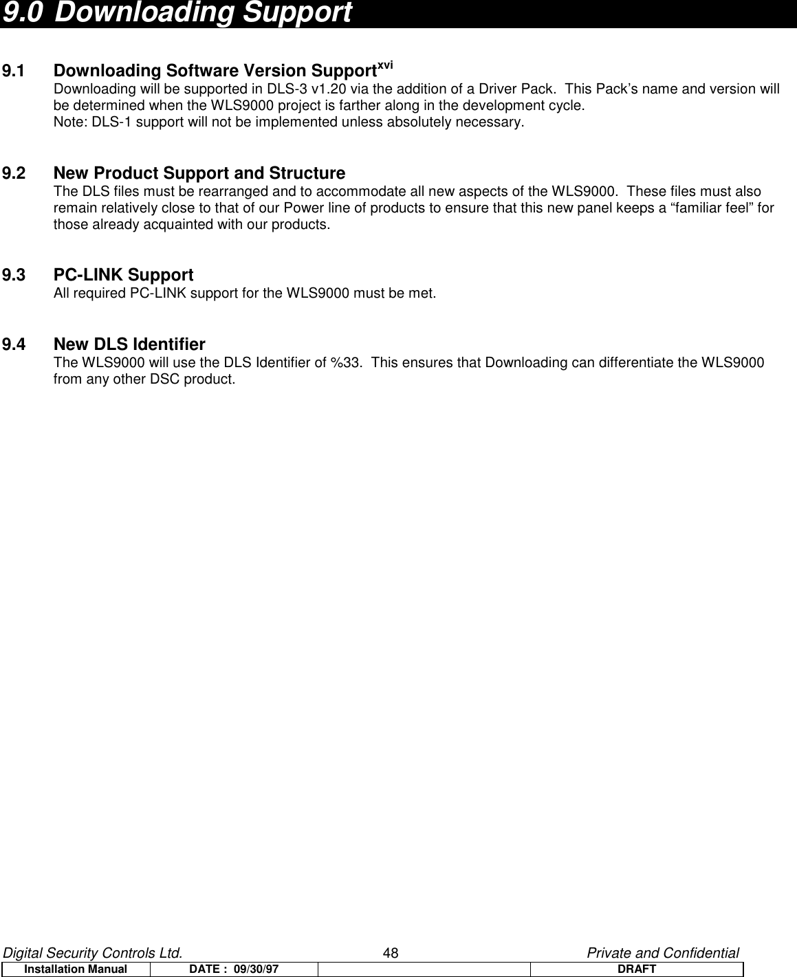
![Digital Security Controls Ltd. 49 Private and ConfidentialInstallation Manual DATE : 09/30/97 DRAFT 10.0 Programming WorksheetsNote: All digits must be entered in a Programming Section for a change to be valid.xviiZONE DEFINITIONS00 Null Zone (Not Used) 10 24 Hour Supervisory Buzzer 20 24 Hour Freeze 01 Delay 1 11 24 Hour Burglary 21 24 Hour Latching Tamper02 Delay 2 12 24 Hour Holdup 22 Momentary Keyswitch Arm03 Instant 13 24 Hour Gas 23 Maintained Keyswitch Arm04 Interior 14 24 Hour Heat 24 Not Used (Reserved)05 Interior, Stay-Away 15 24 Hour Medical 25 Interior Delay06 Delay, Stay-Away 16 24 Hour Panic 87 Delayed 24 Hour Fire (Wireless)07 Not Used 17 24 Hour Emergency 88 Standard 24 Hour Fire (Wireless)08 Not Used 18 24 Hour Sprinkler09 24 Hour Supervisory 19 24 Hour Water[001] ZONE 1-8 DEFINITIONSDefault Default01 I___II___I Zone 1 04 I___II___I Zone 503 I___II___I Zone 2 04 I___II___I Zone 603 I___II___I Zone 3 04 I___II___I Zone 703 I___II___I Zone 4 04 I___II___I Zone 8[002] ZONE 9-16 DEFINITIONSDefault Default00 I___II___I Zone 9 00 I___II___I Zone 1300 I___II___I Zone 10 00 I___II___I Zone 1400 I___II___I Zone 11 00 I___II___I Zone 1500 I___II___I Zone 12 00 I___II___I Zone 16[003] ZONE 17-24 DEFINITIONSDefault Default00 I___II___I Zone 17 00 I___II___I Zone 2100 I___II___I Zone 18 00 I___II___I Zone 2200 I___II___I Zone 19 00 I___II___I Zone 2300 I___II___I Zone 20 00 I___II___I Zone 24[004] ZONE 25-32 DEFINITIONSDefault Default00 I___II___I Zone 25 00 I___II___I Zone 2900 I___II___I Zone 26 00 I___II___I Zone 3000 I___II___I Zone 27 00 I___II___I Zone 3100 I___II___I Zone 28 00 I___II___I Zone 32Note: Zone Definitions can also be programmed via the Wizard.[005] SYSTEM TIMESDefault [001-255]030 I___II___II___I Entry Delay 1 Enter 3 digits from 001-255045 I___II___II___I Entry Delay 2 Enter 3 digits from 001-255120 I___II___II___I Exit Delay Enter 3 digits from 001-255004 I___II___II___I Bell Cut-off Enter 3 digits from 001-255[006] INSTALLER'S CODEDefault 5555 I___II___II___II___I[007] MASTER CODEDefault1234 I___II___II___II___I](https://usermanual.wiki/Tyco-Safety-Canada/99SS9001/User-Guide-68638-Page-49.png)
![Digital Security Controls Ltd. 50 Private and ConfidentialInstallation Manual DATE : 09/30/97 DRAFT[008] MAINTENANCE CODEDefaultAAAA I___II___II___II___I[012] KEYPAD LOCKOUT OPTIONSDefault000 I___II___II___I Number of Invalid Codes Before Lockout (Valid entries are 000-255)000 I___II___II___I Lockout Duration (in minutes) (Valid entries are 000-255)[013] FIRST SYSTEM OPTION CODEDefault Option ON Option OffOFF I___I Option 1 Hardwired Zones are NC Hardwired Zones are EOLOFF I___I Option 2 Not UsedON I___I Option 3 Not UsedOFF I___I Option 4 Tampers/Faults Do Not Sound as Open Tampers/Faults Sound as OpenOFF I___I Option 5 Not UsedON I___I Option 6 Audible Exit Fault Enabled Audible Exit Fault DisabledON I___I Option 7 Event Buffer Follows Swinger Shutdown Event Buffer Logs Events Past shutdownON I___I Option 8 Temporal Three Fire Signal Enabled Standard Pulsed Fire Signal[014] SECOND SYSTEM OPTION CODEDefault Option ON Option OffOFF I___I Option 1 Arm/Disarm Bell Squawk Enabled Arm/Disarm Bell Squawk DisabledOFF I___I Option 2 Bell Squawk During Auto Arm No Bell Squawk During Auto ArmOFF I___I Option 3 Bell Squawk On Exit Delay No Bell Squawk On Exit DelayOFF I___I Option 4 Bell Squawk On Entry Delay No Bell Squawk On Entry DelayOFF I___I Option 5 Bell Squawk on Trouble No Bell Squawk on TroubleON I___I Option 6 Audible Exit With Urgency Silent Exit DelayOFF I___I Option 7 Exit Delay Termination Enabled Exit Delay Termination DisabledOFF I___I Option 8 Fire Bell is Continuous Fire Bell follows Bell Cut-off[015] THIRD SYSTEM OPTION CODEDefault Option ON Option OFFON I___I Option 1 [F] Key Enabled [F] Key DisabledOFF I___I Option 2 [P] Key Audible (Bell / Beeps) [P] Key SilentOFF I___I Option 3 Quick Exit Enabled Quick Exit DisabledON I___I Option 4 Quick Arming Enabled (*0 and Function Keys) Quick Arming Disabled (Keys Req. Code)OFF I___I Option 5 Code Required For Bypassing No Code RequiredOFF I___I Option 6 Master Code Not Changeable Master Code ChangeableON I___I Option 7 TLM Enabled TLM DisabledOFF I___I Option 8 TLM Audible When Armed TLM Trouble Only When Armed[016] FOURTH SYSTEM OPTION CODEDefault Option ON Option OFFOFF I___I Option 1 Not UsedOFF I___I Option 2 Not UsedOFF I___I Option 3 Blank Unit When Not Used Unit Always ActiveOFF I___I Option 4 Code Required to Remove Blanking No Code RequiredON I___I Option 5 Backlighting is Enabled Backlighting is DisabledOFF I___I Option 6 Not UsedOFF I___I Option 7 Bypass Status Displayed While Armed Bypass Status Not Displayed While ArmedOFF I___I Option 8 Not Used](https://usermanual.wiki/Tyco-Safety-Canada/99SS9001/User-Guide-68638-Page-50.png)
![Digital Security Controls Ltd. 51 Private and ConfidentialInstallation Manual DATE : 09/30/97 DRAFT[017] FIFTH SYSTEM OPTION CODEDefault Option ON Option OFFOFF I___I Option 1 WLSKey Does Not Use Access Codes WLSKey Uses Access CodesON I___I Option 2 Verbal Chime is Enabled Verbal Chime is Disabled (Beeps only)ON I___I Option 3 Verbal Alarm is Enabled Verbal Alarm is Disabled (Siren Only)ON I___I Option 4 Local Annunciation Enabled Local Annunciation DisabledxviiiOFF I___I Option 5 Remote Annunciation Enabled Remote Annunciation DisabledOFF I___I Option 6 For Future UseOFF I___I Option 7 For Future UseOFF I___I Option 8 Squawk on Away Arming/Disarming Only Bell Squawk on all Arming/DisarmingADVANCED SYSTEM PROGRAMMINGZONE ATTRIBUTE DEFAULTSZone Type On OffOpt. 1AudibleSilentOpt. 2SteadyPulsedOpt. 3ChimeNoOpt. 4BypassNoOpt. 5ForceNoOpt. 6Swing.NoOpt 7Tx Del.NoOpt. 8WirelessNo00 Null Zone Off Off Off Off Off Off Off On01 Delay 1 On On On On Off On Off On02 Delay 2 On On On On Off On Off On03 Instant On On On On Off On Off On04 Interior On On Off On Off On Off On05 Interior, Stay-Away On On Off On On On Off On06 Delay, Stay-Away On On Off On On On Off On07-08 Not Usedxix Off Off Off Off Off Off Off Off09 24 Hour Supervisory Off On Off Off On Off Off On10 24 Hr Superv. Buzzer Off On Off On Off Off Off On11 24 Hour Burglary On On Off On Off Off Off On12 24 Hour Holdup Off On Off Off Off Off Off On13 24 Hour Gas On Off Off Off Off Off Off On14 24 Hour Heat On Off Off Off Off Off Off On15 24 Hour Medical On On Off Off Off Off Off On16 24 Hour Panic On On Off Off Off Off Off On17 24 Hour Emergency On On Off Off Off Off Off On18 24 Hour Sprinkler On On Off Off Off Off Off On19 24 Hour Water On On Off Off Off Off Off On20 24 Hour Freeze On On Off Off Off Off Off On21 24 Hour Latching Tamper On On Off Off Off Off Off On22 Momentary Keyswitch Off Off Off Off On Off Off On23 Maintained Keyswitch Off Off Off Off On Off Off On24 Not Used Off Off Off Off Off Off Off On25 Interior Delay On On Off On Off On Off On87 Delayed 24Hr Fire (Wireless) On Off Off Off Off Off Off On88 Standard 24Hr Fire (Wireless) On Off Off Off Off Off Off On](https://usermanual.wiki/Tyco-Safety-Canada/99SS9001/User-Guide-68638-Page-51.png)
![Digital Security Controls Ltd. 52 Private and ConfidentialInstallation Manual DATE : 09/30/97 DRAFTZONE 1-32 ATTRIBUTES On OffOpt. 1AudibleSilentOpt. 2SteadyPulsedOpt. 3ChimeNoOpt. 4BypassNoOpt. 5ForceNoOpt. 6Swing.NoOpt 7Tx Del.NoOpt. 8WirelessNo[101] ZONE 1 I____I I____I I____I I____I I____I I____I I____I I____I[102] ZONE 2 I____I I____I I____I I____I I____I I____I I____I I____I[103] ZONE 3 I____I I____I I____I I____I I____I I____I I____I I____I[104] ZONE 4 I____I I____I I____I I____I I____I I____I I____I I____I[105] ZONE 5 I____I I____I I____I I____I I____I I____I I____I I____I[106] ZONE 6 I____I I____I I____I I____I I____I I____I I____I I____I[107] ZONE 7 I____I I____I I____I I____I I____I I____I I____I I____I[108] ZONE 8 I____I I____I I____I I____I I____I I____I I____I I____I[109] ZONE 9 I____I I____I I____I I____I I____I I____I I____I I____I[110] ZONE 10 I____I I____I I____I I____I I____I I____I I____I I____I[111] ZONE 11 I____I I____I I____I I____I I____I I____I I____I I____I[112] ZONE 12 I____I I____I I____I I____I I____I I____I I____I I____I[113] ZONE 13 I____I I____I I____I I____I I____I I____I I____I I____I[114] ZONE 14 I____I I____I I____I I____I I____I I____I I____I I____I[115] ZONE 15 I____I I____I I____I I____I I____I I____I I____I I____I[116] ZONE 16 I____I I____I I____I I____I I____I I____I I____I I____I[117] ZONE 17 I____I I____I I____I I____I I____I I____I I____I I____I[118] ZONE 18 I____I I____I I____I I____I I____I I____I I____I I____I[119] ZONE 19 I____I I____I I____I I____I I____I I____I I____I I____I[120] ZONE 20 I____I I____I I____I I____I I____I I____I I____I I____I[121] ZONE 21 I____I I____I I____I I____I I____I I____I I____I I____I[122] ZONE 22 I____I I____I I____I I____I I____I I____I I____I I____I[123] ZONE 23 I____I I____I I____I I____I I____I I____I I____I I____I[124] ZONE 24 I____I I____I I____I I____I I____I I____I I____I I____I[125] ZONE 25 I____I I____I I____I I____I I____I I____I I____I I____I[126] ZONE 26 I____I I____I I____I I____I I____I I____I I____I I____I[127] ZONE 27 I____I I____I I____I I____I I____I I____I I____I I____I[128] ZONE 28 I____I I____I I____I I____I I____I I____I I____I I____I[129] ZONE 29 I____I I____I I____I I____I I____I I____I I____I I____I[130] ZONE 30 I____I I____I I____I I____I I____I I____I I____I I____I[131] ZONE 31 I____I I____I I____I I____I I____I I____I I____I I____I[132] ZONE 32 I____I I____I I____I I____I I____I I____I I____I I____I](https://usermanual.wiki/Tyco-Safety-Canada/99SS9001/User-Guide-68638-Page-52.png)
![Digital Security Controls Ltd. 53 Private and ConfidentialInstallation Manual DATE : 09/30/97 DRAFT[160] MAXIMUM DIALING ATTEMPTS TO EACH PHONE NUMBER Default008 I___II___II___I Valid entries are 001-015 attempts[161] POST DIAL WAIT FOR HANDSHAKE (ALL FORMATS)Default040 I___II___II___I Valid entries are 001-255 seconds[202] SYSTEM ZONE ASSIGNMENTSDefault Option ON Option OFFON I___I Option 1 Zone 1 is Enabled Zone 1 is DisabledON I___I Option 2 Zone 2 is Enabled Zone 2 is DisabledON I___I Option 3 Zone 3 is Enabled Zone 3 is DisabledON I___I Option 4 Zone 4 is Enabled Zone 4 is DisabledON I___I Option 5 Zone 5 is Enabled Zone 5 is DisabledON I___I Option 6 Zone 6 is Enabled Zone 6 is DisabledON I___I Option 7 Zone 7 is Enabled Zone 7 is DisabledON I___I Option 8 Zone 8 is Enabled Zone 8 is Disabled[203] SYSTEM ZONE ASSIGNMENTS 09-16Default Option ON Option OFFOFF I___I Option 1 Zone 9 is Enabled Zone 9 is DisabledOFF I___I Option 2 Zone 10 is Enabled Zone 10 is DisabledOFF I___I Option 3 Zone 11 is Enabled Zone 11 is DisabledOFF I___I Option 4 Zone 12 is Enabled Zone 12 is DisabledOFF I___I Option 5 Zone 13 is Enabled Zone 13 is DisabledOFF I___I Option 6 Zone 14 is Enabled Zone 14 is DisabledOFF I___I Option 7 Zone 15 is Enabled Zone 15 is DisabledOFF I___I Option 8 Zone 16 is Enabled Zone 16 is Disabled[204] SYSTEM ZONE ASSIGNMENTS 17-24Default Option ON Option OFFOFF I___I Option 1 Zone 17 is Enabled Zone 17 is DisabledOFF I___I Option 2 Zone 18 is Enabled Zone 18 is DisabledOFF I___I Option 3 Zone 19 is Enabled Zone 19 is DisabledOFF I___I Option 4 Zone 20 is Enabled Zone 20 is DisabledOFF I___I Option 5 Zone 21 is Enabled Zone 21 is DisabledOFF I___I Option 6 Zone 22 is Enabled Zone 22 is DisabledOFF I___I Option 7 Zone 23 is Enabled Zone 23 is DisabledOFF I___I Option 8 Zone 24 is Enabled Zone 24 is Disabled[205] SYSTEM ZONE ASSIGNMENTS 25-32Default Option ON Option OFFOFF I___I Option 1 Zone 25 is Enabled Zone 25 is DisabledOFF I___I Option 2 Zone 26 is Enabled Zone 26 is DisabledOFF I___I Option 3 Zone 27 is Enabled Zone 27 is DisabledOFF I___I Option 4 Zone 28 is Enabled Zone 28 is DisabledOFF I___I Option 5 Zone 29 is Enabled Zone 29 is DisabledOFF I___I Option 6 Zone 30 is Enabled Zone 30 is DisabledOFF I___I Option 7 Zone 31 is Enabled Zone 31 is DisabledOFF I___I Option 8 Zone 32 is Enabled Zone 32 is Disabled](https://usermanual.wiki/Tyco-Safety-Canada/99SS9001/User-Guide-68638-Page-53.png)
![Digital Security Controls Ltd. 54 Private and ConfidentialInstallation Manual DATE : 09/30/97 DRAFTCOMMUNICATIONS PROGRAMMING* For Sections [301] to [353], the contents of every section by default is [F].[301] FIRST TELEPHONE NUMBER (32 Digits)I__II__II__II__II__II__II__II__II__II__II__II__II__II__II__II__II__II__II__II__II__II__II__II__II__II__II__II__II__II__II__II__I[302] SECOND TELEPHONE NUMBER (32 Digits)I__II__II__II__II__II__II__II__II__II__II__II__II__II__II__II__II__II__II__II__II__II__II__II__II__II__II__II__II__II__II__II__I[303] THIRD TELEPHONE NUMBER (32 Digits)I__II__II__II__II__II__II__II__II__II__II__II__II__II__II__II__II__II__II__II__II__II__II__II__II__II__II__II__II__II__II__II__I[310] TELEPHONE NUMBER 1/3 ACCOUNT CODE (4 Digits)I__II__II__II__I[311] TELEPHONE NUMBER 2 ACCOUNT CODE (4 Digits)I__II__II__II__I[320] ALARM REPORTING CODES, ZONES 1-8I___II___I Zone 1 Alarm I___II___I Zone 5 AlarmI___II___I Zone 2 Alarm I___II___I Zone 6 AlarmI___II___I Zone 3 Alarm I___II___I Zone 7 AlarmI___II___I Zone 4 Alarm I___II___I Zone 8 Alarm[321] ALARM REPORTING CODES, ZONES 9-16I___II___I Zone 9 Alarm I___II___I Zone 13 AlarmI___II___I Zone 10 Alarm I___II___I Zone 14 AlarmI___II___I Zone 11 Alarm I___II___I Zone 15 AlarmI___II___I Zone 12 Alarm I___II___I Zone 16 Alarm[322] ALARM REPORTING CODES, ZONES 17-24I___II___I Zone 17 Alarm I___II___I Zone 21 AlarmI___II___I Zone 18 Alarm I___II___I Zone 22 AlarmI___II___I Zone 19 Alarm I___II___I Zone 23 AlarmI___II___I Zone 20 Alarm I___II___I Zone 24 Alarm[323] ALARM REPORTING CODES, ZONES 25-32I___II___I Zone 25 Alarm I___II___I Zone 29 AlarmI___II___I Zone 26 Alarm I___II___I Zone 30 AlarmI___II___I Zone 27 Alarm I___II___I Zone 31 AlarmI___II___I Zone 28 Alarm I___II___I Zone 32 Alarm[324] ALARM RESTORAL REPORTING CODES, ZONES 1-8I___II___I Zone 1 Alarm Restore I___II___I Zone 5 Alarm RestoreI___II___I Zone 2 Alarm Restore I___II___I Zone 6 Alarm RestoreI___II___I Zone 3 Alarm Restore I___II___I Zone 7 Alarm RestoreI___II___I Zone 4 Alarm Restore I___II___I Zone 8 Alarm Restore[325] ALARM RESTORAL REPORTING CODES, ZONES 9-16I___II___I Zone 9 Alarm Restore I___II___I Zone 13 Alarm RestoreI___II___I Zone 10 Alarm Restore I___II___I Zone 14 Alarm RestoreI___II___I Zone 11 Alarm Restore I___II___I Zone 15 Alarm RestoreI___II___I Zone 12 Alarm Restore I___II___I Zone 16 Alarm Restore](https://usermanual.wiki/Tyco-Safety-Canada/99SS9001/User-Guide-68638-Page-54.png)
![Digital Security Controls Ltd. 55 Private and ConfidentialInstallation Manual DATE : 09/30/97 DRAFT[326] ALARM RESTORE REPORTING CODES, ZONES 17-24I___II___I Zone 17 Alarm Restore I___II___I Zone 21 Alarm RestoreI___II___I Zone 18 Alarm Restore I___II___I Zone 22 Alarm RestoreI___II___I Zone 19 Alarm Restore I___II___I Zone 23 Alarm RestoreI___II___I Zone 20 Alarm Restore I___II___I Zone 24 Alarm Restore[327] ALARM REPORTING CODES, ZONES 25-32I___II___I Zone 25 Alarm Restore I___II___I Zone 29 Alarm RestoreI___II___I Zone 26 Alarm Restore I___II___I Zone 30 Alarm RestoreI___II___I Zone 27 Alarm Restore I___II___I Zone 31 Alarm RestoreI___II___I Zone 28 Alarm Restore I___II___I Zone 32 Alarm Restore[328] MISCELLANEOUS ALARM REPORTING CODESI___II___I Duress Alarm I___II___I Not UsedI___II___I Opening After Alarm I___II___I Not UsedI___II___I Recent Closing I___II___I Cross Zone Police Code Alarm[329] PRIORITY ALARM AND RESTORAL REPORTING CODESI___II___I Keypad [F]ire Alarm I___II___I Keypad [F]ire RestoralI___II___I Keypad [A]uxiliary Alarm I___II___I Keypad [A]uxiliary RestoralI___II___I Keypad [P]anic Alarm I___II___I Keypad [P]anic RestoralI___II___I Not Used I___II___I Not Used[330] TAMPER REPORTING CODES, ZONES 1-8I___II___I Zone 1 Tamper I___II___I Zone 5 TamperI___II___I Zone 2 Tamper I___II___I Zone 6 TamperI___II___I Zone 3 Tamper I___II___I Zone 7 TamperI___II___I Zone 4 Tamper I___II___I Zone 8 Tamper[331] TAMPER REPORTING CODES, ZONES 9-16I___II___I Zone 9 Tamper I___II___I Zone 13 TamperI___II___I Zone 10 Tamper I___II___I Zone 14 TamperI___II___I Zone 11 Tamper I___II___I Zone 15 TamperI___II___I Zone 12 Tamper I___II___I Zone 16 Tamper[332] TAMPER REPORTING CODES, ZONES 17-24I___II___I Zone 17 Tamper I___II___I Zone 21 TamperI___II___I Zone 18 Tamper I___II___I Zone 22 TamperI___II___I Zone 19 Tamper I___II___I Zone 23 TamperI___II___I Zone 20 Tamper I___II___I Zone 24 Tamper[333] TAMPER REPORTING CODES, ZONES 17-24I___II___I Zone 25 Tamper I___II___I Zone 29 TamperI___II___I Zone 26 Tamper I___II___I Zone 30 TamperI___II___I Zone 27 Tamper I___II___I Zone 31 TamperI___II___I Zone 28 Tamper I___II___I Zone 32 Tamper[334] TAMPER RESTORAL REPORTING CODES, ZONES 1-8I___II___I Zone 1 Tamper Restoral I___II___I Zone 5 Tamper RestoralI___II___I Zone 2 Tamper Restoral I___II___I Zone 6 Tamper RestoralI___II___I Zone 3 Tamper Restoral I___II___I Zone 7 Tamper RestoralI___II___I Zone 4 Tamper Restoral I___II___I Zone 8 Tamper Restoral](https://usermanual.wiki/Tyco-Safety-Canada/99SS9001/User-Guide-68638-Page-55.png)
![Digital Security Controls Ltd. 56 Private and ConfidentialInstallation Manual DATE : 09/30/97 DRAFT[335] TAMPER RESTORAL REPORTING CODES, ZONES 9-16I___II___I Zone 9 Tamper Restoral I___II___I Zone 13 Tamper RestoralI___II___I Zone 10 Tamper Restoral I___II___I Zone 14 Tamper RestoralI___II___I Zone 11 Tamper Restoral I___II___I Zone 15 Tamper RestoralI___II___I Zone 12 Tamper Restoral I___II___I Zone 16 Tamper Restoral[336] TAMPER RESTORAL REPORTING CODES, ZONES 17-24I___II___I Zone 17 Tamper Restoral I___II___I Zone 21 Tamper RestoralI___II___I Zone 18 Tamper Restoral I___II___I Zone 22 Tamper RestoralI___II___I Zone 19 Tamper Restoral I___II___I Zone 23 Tamper RestoralI___II___I Zone 20 Tamper Restoral I___II___I Zone 24 Tamper Restoral[337] TAMPER RESTORAL REPORTING CODES, ZONES 17-24I___II___I Zone 25 Tamper Restoral I___II___I Zone 29 Tamper RestoralI___II___I Zone 26 Tamper Restoral I___II___I Zone 30 Tamper RestoralI___II___I Zone 27 Tamper Restoral I___II___I Zone 31 Tamper RestoralI___II___I Zone 28 Tamper Restoral I___II___I Zone 32 Tamper Restoral[338] MISCELLANEOUS TAMPER REPORTING CODESI___II___I Keypad Lockoutxx[339] CLOSING (ARMING) REPORTING CODES, ACCESS CODES 1-8I___II___I Closing by Access Code 1 I___II___I Closing by Access Code 5I___II___I Closing by Access Code 2 I___II___I Closing by Access Code 6I___II___I Closing by Access Code 3 I___II___I Closing by Access Code 7I___II___I Closing by Access Code 4 I___II___I Closing by Access Code 8[340] CLOSING (ARMING) REPORTING CODES, ACCESS CODES 9-16I___II___I Closing by Access Code 9 I___II___I Closing by Access Code 13I___II___I Closing by Access Code 10 I___II___I Closing by Access Code 14I___II___I Closing by Access Code 11 I___II___I Closing by Access Code 15I___II___I Closing by Access Code 12 I___II___I Closing by Access Code 16[341] CLOSING (ARMING) REPORTING CODES, ACCESS CODES 17-24I___II___I Closing by Access Code 17 I___II___I Closing by Access Code 21I___II___I Closing by Access Code 18 I___II___I Closing by Access Code 22I___II___I Closing by Access Code 19 I___II___I Closing by Access Code 23I___II___I Closing by Access Code 20 I___II___I Closing by Access Code 24[342] CLOSING (ARMING) REPORTING CODES, ACCESS CODES 25-32I___II___I Closing by Access Code 25 I___II___I Closing by Access Code 29I___II___I Closing by Access Code 26 I___II___I Closing by Access Code 30I___II___I Closing by Access Code 27 I___II___I Closing by Access Code 31I___II___I Closing by Access Code 28 I___II___I Closing by Access Code 32[343] MISCELLANEOUS CLOSING (ARMING) REPORTING CODESI___II___I Closing by Duress Code 33 I___II___I Closing by System Code 42I___II___I Closing by Duress Code 34 I___II___I Partial ClosingI___II___I Closing by System Code 40 I___II___I Special ClosingI___II___I Closing by System Code 41](https://usermanual.wiki/Tyco-Safety-Canada/99SS9001/User-Guide-68638-Page-56.png)
![Digital Security Controls Ltd. 57 Private and ConfidentialInstallation Manual DATE : 09/30/97 DRAFT[344] OPENING (DISARMING) REPORTING CODES, ACCESS CODES 1-8I___II___I Opening by Access Code 1 I___II___I Opening by Access Code 5I___II___I Opening by Access Code 2 I___II___I Opening by Access Code 6I___II___I Opening by Access Code 3 I___II___I Opening by Access Code 7I___II___I Opening by Access Code 4 I___II___I Opening by Access Code 8[345] OPENING (DISARMING) REPORTING CODES, ACCESS CODES 9-16I___II___I Opening by Access Code 9 I___II___I Opening by Access Code 13I___II___I Opening by Access Code 10 I___II___I Opening by Access Code 14I___II___I Opening by Access Code 11 I___II___I Opening by Access Code 15I___II___I Opening by Access Code 12 I___II___I Opening by Access Code 16[346] OPENING (DISARMING) REPORTING CODES, ACCESS CODES 17-24I___II___I Opening by Access Code 17 I___II___I Opening by Access Code 21I___II___I Opening by Access Code 18 I___II___I Opening by Access Code 22I___II___I Opening by Access Code 19 I___II___I Opening by Access Code 23I___II___I Opening by Access Code 20 I___II___I Opening by Access Code 24[347] OPENING (DISARMING) REPORTING CODES, ACCESS CODES 25-32I___II___I Opening by Access Code 25 I___II___I Opening by Access Code 29I___II___I Opening by Access Code 26 I___II___I Opening by Access Code 30I___II___I Opening by Access Code 27 I___II___I Opening by Access Code 31I___II___I Opening by Access Code 28 I___II___I Opening by Access Code 32[348] MISCELLANEOUS OPENING (DISARMING) REPORTING CODESI___II___I Opening by Duress Code 33 I___II___I Opening by System Code 42I___II___I Opening by Duress Code 34 I___II___I Auto-arm CancellationI___II___I Opening by System Code 40 I___II___I Special OpeningI___II___I Opening by System Code 41[349] MAINTENANCE ALARM REPORTING CODESI___II___I Battery Trouble Alarm I___II___I Not UsedI___II___I AC Failure Trouble Alarm I___II___I Not UsedI___II___I Remote Sounder Trouble Alarm I___II___I General System TroubleI___II___I Fire Trouble Alarm I___II___I Not Used[350] MAINTENANCE RESTORAL REPORTING CODESI___II___I Battery Trouble Restoral I___II___I Not UsedI___II___I AC Failure Trouble Restoral I___II___I TLM RestoralI___II___I Remote Sounder Restoral I___II___I General System Trouble RestoreI___II___I Fire Trouble Restoral I___II___I Not Used[351] MISCELLANEOUS MAINTENANCE REPORTING CODESI___II___I Phone #1 FTC Restore I___II___I DLS Lead OUTI___II___I Phone #2 FTC Restore I___II___I Zone Fault AlarmI___II___I Event Buffer 75% Full I___II___I Zone Fault RestoreI___II___I DLS Lead IN I___II___I Delinquency Reporting Code[352] TEST TRANSMISSION REPORTING CODESI___II___I Periodic Test Transmission I___II___I Not UsedI___II___I System Test[353] WIRELESS MAINTENANCE REPORTING CODESI___II___I General Zone Low Battery Alarm I___II___I General Zone Low Battery Restore[360] COMMUNICATOR FORMAT OPTIONS](https://usermanual.wiki/Tyco-Safety-Canada/99SS9001/User-Guide-68638-Page-57.png)
![Digital Security Controls Ltd. 58 Private and ConfidentialInstallation Manual DATE : 09/30/97 DRAFT01 20 BPS, 1400 Hz handshake Note: 3rd Phone Number follows the02 20 BPS, 2300 Hz handshake format of the 1st Phone Number03 DTMF CONTACT I.D. 04 SIA FSK05 PagerDefault04 I___II___I 1st Phone Number04 I___II___I 2nd Phone Number[361] ALARM / RESTORE COMMUNICATOR CALL DIRECTIONSDefault Option ON Option OFFON I___I Option 1 1st Telephone Number DisabledOFF I___I Option 2 2nd Telephone Number DisabledOFF I___I Option 3-8 For Future Use[363] TAMPER ALARM / RESTORE COMMUNICATOR CALL DIRECTIONSDefault Option ON Option OFFON I___I Option 1 1st Telephone Number DisabledOFF I___I Option 2 2nd Telephone Number DisabledOFF I___I Option 3-8 For Future Use[365] OPENING / CLOSING COMMUNICATOR CALL DIRECTIONSDefault Option ON Option OFFON I___I Option 1 1st Telephone Number DisabledOFF I___I Option 2 2nd Telephone Number DisabledOFF I___I Option 3-8 For Future Use[367] SYSTEM MAINTENANCE ALARM / RESTORE COMMUNICATOR CALL DIRECTIONSDefault Option ON Option OFFON I___I Option 1 1st Telephone Number DisabledOFF I___I Option 2 2nd Telephone Number DisabledOFF I___I Option 3-8 For Future Use[368] SYSTEM TEST TRANSMISSIONS COMMUNICATOR CALL DIRECTIONSDefault Option ON Option OFFON I___I Option 1 1st Telephone Number DisabledOFF I___I Option 2 2nd Telephone Number DisabledOFF I___I Option 3-8 For Future Use[370] COMMUNICATION VARIABLESDefault003 I___II___II___I Swinger Shutdown (Alarms & Rest) (000-255 Transmissions, 000=disabled)003 I___II___II___I Swinger Shutdown (Tampers & Rest) (000-255 Transmissions, 000=disabled)003 I___II___II___I Swinger Shutdown (Maint & Rest) (000-255 Transmissions, 000=disabled)000 I___II___II___I Communication Delay (000-255 seconds)030 I___II___II___I AC Failure Communication Delay (000-255 minutes)003 I___II___II___I TLM Trouble Delay (# of valid checks required +3= 003-255x10s)030 I___II___II___I Test Transmission Cycle (land-line) (000-255 days)/(000-255 mins)007 I___II___II___I Zone Low Battery Transmission Delay (000-255 days)030 I___II___II___I Delinquency Transmission Delay (000-255 days/hours)[371] TEST TRANSMISSION TIME OF DAY](https://usermanual.wiki/Tyco-Safety-Canada/99SS9001/User-Guide-68638-Page-58.png)
![Digital Security Controls Ltd. 59 Private and ConfidentialInstallation Manual DATE : 09/30/97 DRAFTDefault9999 I___II___II___II___I (Valid entries are 0000-2359, 9999 to disable)[380] FIRST COMMUNICATOR OPTION CODEDefault Option ON Option OFFON I___I Option 1 Communications Enabled Communications DisabledOFF I___I Option 2 Restorals on Bell Time-out Restorals Follow ZonesOFF I___I Option 3 Pulse Dialing DTMF DialingON I___I Option 4 Switch to Pulse Dialing on 5th Attempt DTMF Dial For All 8 AttemptsOFF I___I Option 5 3rd Phone Number Enabled 3rd Phone Number DisabledOFF I___I Option 6 Alternate Dial (1st & 3rd) Call 1st Number, Backup to 3rdOFF I___I Option 7 Not UsedOFF I___I Option 8 Delinquency Follows Zone Activity (Hours) Delinquency Follows Arming (Days)[381] SECOND COMMUNICATOR OPTION CODEDefault Option ON Option OFFOFF I___I Option 1 Opening After Alarm Kypd Ringback Enabled Opn After Alrm Kypd Ringback DisabledOFF I___I Option 2 Opening After Alarm Bell Ringback Enabled Opn After Alrm Bell Ringback DisabledOFF I___I Option 3 SIA Uses Programmed Rep. Codes SIA Uses Automatic Rep. CodesOFF I___I Option 4 Closing Confirmation Enabled Closing Confirmation DisabledON I___I Option 5 Talk/Listen on Phone #1/3 Enabled Talk/Listen on Phone #1/3 DisabledOFF I___I Option 6 Talk/Listen on Phone #2 Enabled Talk/Listen on Phone #2 DisabledON I___I Option 7 Contact I.D. Uses Pgm’d Rep. Codes Contact I.D. Uses Auto Rep. CodesOFF I___I Option 8 For Future UseDOWNLOADING PROGRAMMING[401] FIRST DOWNLOADING OPTION CODEDefault Option ON Option OFFOFF I___I Option 1 Answering Machine / Double Call Enabled Answ. Machine / Double Call DisabledON I___I Option 2 User Can Enable DLS Window User Can Not Enable DLS WindowOFF I___I Option 3 Call-Back Enabled Call-Back DisabledOFF I___I Option 4 User Initiated Call-up Enabled User Initiated Call-up DisabledOFF I___I Option 5 Auto Event Buffer Upload Enabled Auto Event Buffer Upload DisabledOFF I___I Option 6 For Future UseOFF I___I Option 7 For Future UseOFF I___I Option 8 For Future Use[402] DOWNLOADING COMPUTER'S TELEPHONE NUMBER (32 Digits)I__II__II__II__II__II__II__II__II__II__II__II__II__II__II__II__II__II__II__II__II__II__II__II__II__II__II__II__II__II__II__II__I[403] DOWNLOADING ACCESS CODEDefault 9000 I__II__II__II__I Enter 4 Hexadecimal Digits.[404] PANEL IDENTIFICATION CODEDefault 9000 I__II__II__II__I Enter 4 Hexadecimal Digits.](https://usermanual.wiki/Tyco-Safety-Canada/99SS9001/User-Guide-68638-Page-59.png)
![Digital Security Controls Ltd. 60 Private and ConfidentialInstallation Manual DATE : 09/30/97 DRAFT[405] ANSWERING MACHINE DOUBLE-CALL TIMERDefault060 I__II__II__I (Valid entries are 001-255 seconds)[406] NUMBER OF RINGS TO ANSWER ONDefault000 I__II__II__I (Valid entries are 000-255 rings)[499][Installer Code][499] INITIATE PCLINK• ENTER [499] [INSTALLER CODE] [499]INTERNATIONAL PROGRAMMING[700] AUTOMATIC CLOCK ADJUSTDefault 60 I___II___I (Valid entries are 00-99)[701] FIRST INTERNATIONAL OPTIONS CODEDefault Option ON Option OFFOFF I___I Option 1 50 Hz AC 60 Hz ACOFF I___I Option 2 Time Base is Internal Crystal Time Base is AC LineOFF I___I Option 3 AC/DC Arming Inhibit Enabled AC/DC Arming Inhibit DisabledOFF I___I Option 4 All System Tampers Require Installer Reset All System Tampers follow RestoreOFF I___I Option 5 6-Digit User Access Codes 4-Digit User Access CodesOFF I___I Option 6 Busy Tone Detection Enabled Busy Tone Detection DisabledOFF I___I Option 7 High Current Battery Charge Standard Current Battery ChargeOFF I___I Option 8 For Future Use[702] SECOND INTERNATIONAL OPTIONS CODEDefault Option ON Option OFFOFF I___I Option 1 Pulse Dialing Make/Break Ratio is 33/67 Pulse Dialing Make/Break Ratio is 40/60ON I___I Option 2 Force Dialing Enabled Force Dialing DisabledOFF I___I Option 3 Land Line Test Tx Interval is in Minutes Land Line Test Tx Interval is in DaysOFF I___I Option 4 1600 Hz Handshake Standard HandshakeOFF I___I Option 5 ID Tone Enabled ID Tone DisabledOFF I___I Option 6 2100 HZ ID Tone 1300 Hz ID ToneOFF I___I Option 7 One Time 1-Hr User Enabled DLS Window Full 6-Hr User Enabled DLS WindowOFF I___I Option 8 Bell on FTC when armed FTC Trouble only when armed[703] DELAY BETWEEN DIALING ATTEMPTSDefault001 I___II___II___I (Valid entries are 000-255 seconds) [801] NOT USED[802] AUDIO INTERFACE[10] Port Assignments, Zones 1-8• Enter the nearest Intercom Port Number (01= Main Unit, 02= Remote Sounder, 00 = Not Used)](https://usermanual.wiki/Tyco-Safety-Canada/99SS9001/User-Guide-68638-Page-60.png)
![Digital Security Controls Ltd. 61 Private and ConfidentialInstallation Manual DATE : 09/30/97 DRAFTDefault00 I___II___I Zone 1 Port Assignment00 I___II___I Zone 2 Port Assignment00 I___II___I Zone 3 Port Assignment00 I___II___I Zone 4 Port Assignment00 I___II___I Zone 5 Port Assignment00 I___II___I Zone 6 Port Assignment00 I___II___I Zone 7 Port Assignment00 I___II___I Zone 8 Port Assignment[11] Port Assignments, Zones 9-16• Enter the nearest Intercom Port Number (01= Main Unit, 02= Remote Sounder, 00 = Not Used)Default00 I___II___I Zone 9 Port Assignment00 I___II___I Zone 10 Port Assignment00 I___II___I Zone 11 Port Assignment00 I___II___I Zone 12 Port Assignment00 I___II___I Zone 13 Port Assignment00 I___II___I Zone 14 Port Assignment00 I___II___I Zone 15 Port Assignment00 I___II___I Zone 16 Port Assignment [12] Port Assignments, Zones 17-24• Enter the nearest Intercom Port Number (01= Main Unit, 02= Remote Sounder, 00 = Not Used)Default00 I___II___I Zone 17 Port Assignment00 I___II___I Zone 18 Port Assignment00 I___II___I Zone 19 Port Assignment00 I___II___I Zone 20 Port Assignment00 I___II___I Zone 21 Port Assignment00 I___II___I Zone 22 Port Assignment00 I___II___I Zone 23 Port Assignment00 I___II___I Zone 24 Port Assignment[13] Port Assignments, Zones 25-32• Enter the nearest Intercom Port Number (01= Main Unit, 02= Remote Sounder, 00 = Not Used)Default00 I___II___I Zone 25 Port Assignment00 I___II___I Zone 26 Port Assignment00 I___II___I Zone 27 Port Assignment00 I___II___I Zone 28 Port Assignment00 I___II___I Zone 29 Port Assignment00 I___II___I Zone 30 Port Assignment00 I___II___I Zone 31 Port Assignment00 I___II___I Zone 32 Port Assignment[20] General Broadcast MaskDefault Option ON Option OFFOff I___I Option 1 For Future UseOn I___I Option 2 Incoming Sounds on Main Unit Enabled Incoming Sounds on Main Unit DisabledOff I___I Option 3 Incoming Sounds on Rem. Sndr Enab. Incoming Sounds on Rem Sndr. DisabledOff I___I Option 4-8 Not Used](https://usermanual.wiki/Tyco-Safety-Canada/99SS9001/User-Guide-68638-Page-61.png)
![Digital Security Controls Ltd. 62 Private and ConfidentialInstallation Manual DATE : 09/30/97 DRAFTAUDIO CONTROL TELEPHONE KEY FUNCTIONS[00] Unused Key[01] Talk To All Speakers[02] Not Used[03] High Gain Listen To All[04] Not Used[05] Not Used[06] Low Gain Listen To All[07] Extend Time[08] For Future Use[09] Terminate Session[10] For Future Use[11] Cancel First Keypress[12] For Future Use[13] Zone Select (0 3 only)[14] Increment Selected Microphone (Input)[15] Decrement Selected Microphone (Input)[16]-[17] Not Used[40] Audio Control Telephone Key ProgrammingDefault01 I___II___I [1] Key00 I___II___I [2] Key03 I___II___I [3] Key14 I___II___I [4] Key15 I___II___I [5] Key 06 I___II___I [6] Key07 I___II___I [7] Key00 I___II___I [8] Key17 I___II___I [9] Key00 I___II___I [0] Key17 I___II___I [*] Key11 I___II___I [#] Key[54] Fifth Audio Control Option CodeDefault Option ON Option OFFOFF I___I Option 1 Tampers Enabled Disabled OFF I___I Option 2 Openings & Closings Enabled DisabledOFF I___I Option 3 [A] Key Alarm Enabled DisabledOFF I___I Option 4 [P] Key Alarm Enabled (Listen) DisabledOFF I___I Option 5 Duress Alarm Enabled (Listen) DisabledOFF I___I Option 6 Not UsedOFF I___I Option 7 Opening After Alarm Enabled DisabledOFF I___I Option 8 For Future UseNOTE: If any event is enabled for Talk/Listen In, Communications MUST be enabled.[55] Audio DurationDefault90 I___II___I (Valid entries are 01-99 Seconds)[60] Telephone Ring MaskDefault Option ON Option OFF](https://usermanual.wiki/Tyco-Safety-Canada/99SS9001/User-Guide-68638-Page-62.png)
![Digital Security Controls Ltd. 63 Private and ConfidentialInstallation Manual DATE : 09/30/97 DRAFTOff I___I Option 1 For Future UseOff I___I Option 2 Main Unit Telephone Ring Enabled Main Unit Telephone Ring DisabledOff I___I Option 3 Remote Sounder Telephone Ring Enab. Remote Sounder Telephone Ring DisabledOff I___I Option 4-8 Not Used[803] NOT USED[804] WIRELESS RECEIVER PROGRAMMING[01] Zone 1 Serial Number 000000 I___II___II___II___II___II___I• 6 digit Hexadecimal entry is required• 1st digit represents Transmitter Type:2 = UTX 5 = Panic Pendant3 = Sensors (PIR, Glassbreak) 6/9 = WLSKey4 = Smoke 7 = Handheld Keypad• 0 must be entered in front of transmitters that have only 5 digit serial numbers[02] Zone 2 Serial Number 000000 I___II___II___II___II___II___I[03] Zone 3 Serial Number 000000 I___II___II___II___II___II___I[04] Zone 4 Serial Number 000000 I___II___II___II___II___II___I[05] Zone 5 Serial Number 000000 I___II___II___II___II___II___I[06] Zone 6 Serial Number 000000 I___II___II___II___II___II___I[07] Zone 7 Serial Number 000000 I___II___II___II___II___II___I[08] Zone 8 Serial Number 000000 I___II___II___II___II___II___I[09] Zone 9 Serial Number 000000 I___II___II___II___II___II___I[10] Zone 10 Serial Number 000000 I___II___II___II___II___II___I[11] Zone 11 Serial Number 000000 I___II___II___II___II___II___I[12] Zone 12 Serial Number 000000 I___II___II___II___II___II___I[13] Zone 13 Serial Number 000000 I___II___II___II___II___II___I[14] Zone 14 Serial Number 000000 I___II___II___II___II___II___I[15] Zone 15 Serial Number 000000 I___II___II___II___II___II___I[16] Zone 16 Serial Number 000000 I___II___II___II___II___II___I[17] Zone 17 Serial Number 000000 I___II___II___II___II___II___I[18] Zone 18 Serial Number 000000 I___II___II___II___II___II___I[19] Zone 19 Serial Number 000000 I___II___II___II___II___II___I[20] Zone 20 Serial Number 000000 I___II___II___II___II___II___I[21] Zone 21 Serial Number 000000 I___II___II___II___II___II___I[22] Zone 22 Serial Number 000000 I___II___II___II___II___II___I[23] Zone 23 Serial Number 000000 I___II___II___II___II___II___I[24] Zone 24 Serial Number 000000 I___II___II___II___II___II___I[25] Zone 25 Serial Number 000000 I___II___II___II___II___II___I[26] Zone 26 Serial Number 000000 I___II___II___II___II___II___I[27] Zone 27 Serial Number 000000 I___II___II___II___II___II___I[28] Zone 28 Serial Number 000000 I___II___II___II___II___II___I[29] Zone 29 Serial Number 000000 I___II___II___II___II___II___I[30] Zone 30 Serial Number 000000 I___II___II___II___II___II___I[31] Zone 31 Serial Number 000000 I___II___II___II___II___II___I[32] Zone 32 Serial Number 000000 I___II___II___II___II___II___IHANDHELD KEYPAD SERIAL NUMBERS[33] Keypad #1 Serial Number 000000 I___II___II___II___II___II___I[34] Keypad #2 Serial Number 000000 I___II___II___II___II___II___I](https://usermanual.wiki/Tyco-Safety-Canada/99SS9001/User-Guide-68638-Page-63.png)
![Digital Security Controls Ltd. 64 Private and ConfidentialInstallation Manual DATE : 09/30/97 DRAFT[35] Keypad #3 Serial Number 000000 I___II___II___II___II___II___I[36] Keypad #4 Serial Number 000000 I___II___II___II___II___II___IWIRELESS KEY SERIAL NUMBERS[41] Wireless Key #01 Serial Number 000000 I___II___II___II___II___II___I[42] Wireless Key #02 Serial Number 000000 I___II___II___II___II___II___I[43] Wireless Key #03 Serial Number 000000 I___II___II___II___II___II___I[44] Wireless Key #04 Serial Number 000000 I___II___II___II___II___II___I[45] Wireless Key #05 Serial Number 000000 I___II___II___II___II___II___I[46] Wireless Key #06 Serial Number 000000 I___II___II___II___II___II___I[47] Wireless Key #07 Serial Number 000000 I___II___II___II___II___II___I[48] Wireless Key #08 Serial Number 000000 I___II___II___II___II___II___I[49] Wireless Key #09 Serial Number 000000 I___II___II___II___II___II___I[50] Wireless Key #10 Serial Number 000000 I___II___II___II___II___II___I[51] Wireless Key #11 Serial Number 000000 I___II___II___II___II___II___I[52] Wireless Key #12 Serial Number 000000 I___II___II___II___II___II___I[53] Wireless Key #13 Serial Number 000000 I___II___II___II___II___II___I[54] Wireless Key #14 Serial Number 000000 I___II___II___II___II___II___I[55] Wireless Key #15 Serial Number 000000 I___II___II___II___II___II___I[56] Wireless Key #16 Serial Number 000000 I___II___II___II___II___II___INote: Serial Numbers are also Programmed via the Wizard.](https://usermanual.wiki/Tyco-Safety-Canada/99SS9001/User-Guide-68638-Page-64.png)
![Digital Security Controls Ltd. 65 Private and ConfidentialInstallation Manual DATE : 09/30/97 DRAFTHANDHELD KEYPAD / WIRELESS KEY FUNCTION KEY OPTIONSEntry Description Handheld Keypad Wireless Key00 Null Key (Key Not Used) YES YES01 Partition 1 Select (Not Used) NO NO02 Partition 2 Select (Not Used) NO NO03 Stay Arm YES YES04 Away Arm YES YES05 [*][9] No-Entry Arm YES NO06 [*][4] Chime On / Off YES YES07 [*][6][----][4] System Test YES YES08 [*][1] Bypass Mode (Not Used) NO NO09 [*][2] Trouble Display (Not Used) NO NO10 [*][3] Alarm Memory (Not Used) NO NO11 [*][5] User Programming (Not Used) NO NO12 [*][6] User Functions (Not Used) NO NO13 Command Output 1 [*][7][1] YES YES14 Command Output 2 [*][7][2] YES YES15 General Voice Prompted Help (Not Used) NO NO16 [*][0] Quick Exit YES YES17 [*][1] Activate Stay Aways YES YES18 Identified Voice Prompted Help (Not Used) NO NO19 Command Output 3 [*][7][3] YES YES20 Pendant Test (Not Used) NO NO21 Command Output 4 [*][7][4] YES YES22-26 For Future Use/Not Used NO NO27 Disarm (Off) NO YES28 Fire Alarm NO YES29 Auxiliary Alarm NO YES30 Panic Alarm NO YESNote: If using Unidentified Wireless Keys for arming, Quick Arming must be enabled.If using Unidentified Wireless Keys for activating PGM Outputs, the option for requiring access code for activation MUST be OFF.Defaultxxi[57] Keypad Function Key 1 03 I___I I___I[58] Keypad Function Key 2 04 I___I I___I[59] Keypad Function Key 3 16 I___I I___I[60] Keypad Function Key 4 31 I___I I___I[61] Wireless Key Function Key 1 03 I___I I___I[62] Wireless Key Function Key 2 04 I___I I___I[63] Wireless Key Function Key 3 27 I___I I___I[64] Wireless Key Function Key 4 31 I___I I___I](https://usermanual.wiki/Tyco-Safety-Canada/99SS9001/User-Guide-68638-Page-65.png)
![Digital Security Controls Ltd. 66 Private and ConfidentialInstallation Manual DATE : 09/30/97 DRAFTDefaultxxii[71] Hardwired Zone Loop #1 Assignment 00 I___II___I (Valid entries are Zones 01-32)[72] Hardwired Zone Loop #2 Assignment 00 I___II___INote: Hardwired Zones override any Wireless Zones that may be programmed for the same zone number.Fire Zones are not supported on these Zone Loops.SUPERVISION[81] WIRELESS SUPERVISORY WINDOWDefault03 I___II___I RF Transmitter Supervisory Window (hours), Valid entries are 01-24MANUAL NOTE: Panic Transmitters are NOT supervised and must be disabled in these sections.[82] ZONE TRANSMITTER SUPERVISION OPTIONS (1-8)Default Option ON Option OFFON I___I Option 1 Zone 01 Supervision Enabled Zone 01 Superv. DisabledON I___I Option 2 Zone 02 Supervision Enabled Zone 02 Superv. DisabledON I___I Option 3 Zone 03 Supervision Enabled Zone 03 Superv. DisabledON I___I Option 4 Zone 04 Supervision Enabled Zone 04 Superv. DisabledON I___I Option 5 Zone 05 Supervision Enabled Zone 05 Superv. DisabledON I___I Option 6 Zone 06 Supervision Enabled Zone 06 Superv. DisabledON I___I Option 7 Zone 07 Supervision Enabled Zone 07 Superv. DisabledON I___I Option 8 Zone 08 Supervision Enabled Zone 08 Superv. Disabled[83] ZONE TRANSMITTER SUPERVISION OPTIONS (9-16)Default Option ON Option OFFON I___I Option 1 Zone 09 Supervision Enabled Zone 09 Superv. DisabledON I___I Option 2 Zone 10 Supervision Enabled Zone 10 Superv. DisabledON I___I Option 3 Zone 11 Supervision Enabled Zone 11 Superv. DisabledON I___I Option 4 Zone 12 Supervision Enabled Zone 12 Superv. DisabledON I___I Option 5 Zone 13 Supervision Enabled Zone 13 Superv. DisabledON I___I Option 6 Zone 14 Supervision Enabled Zone 14 Superv. DisabledON I___I Option 7 Zone 15 Supervision Enabled Zone 15 Superv. DisabledON I___I Option 8 Zone 16 Supervision Enabled Zone 16 Superv. Disabled[84] ZONE TRANSMITTER SUPERVISION OPTIONS (17-24)Default Option ON Option OFFON I___I Option 1 Zone 17 Supervision Enabled Zone 17 Superv. DisabledON I___I Option 2 Zone 18 Supervision Enabled Zone 18 Superv. DisabledON I___I Option 3 Zone 19 Supervision Enabled Zone 19 Superv. DisabledON I___I Option 4 Zone 20 Supervision Enabled Zone 20 Superv. DisabledON I___I Option 5 Zone 21 Supervision Enabled Zone 21 Superv. DisabledON I___I Option 6 Zone 22 Supervision Enabled Zone 22 Superv. DisabledON I___I Option 7 Zone 23 Supervision Enabled Zone 23 Superv. DisabledON I___I Option 8 Zone 24 Supervision Enabled Zone 24 Superv. Disabled[85] ZONE TRANSMITTER SUPERVISION OPTIONS (25-32)Default Option ON Option OFFON I___I Option 1 Zone 25 Supervision Enabled Zone 25 Superv. DisabledON I___I Option 2 Zone 26 Supervision Enabled Zone 26 Superv. Disabled](https://usermanual.wiki/Tyco-Safety-Canada/99SS9001/User-Guide-68638-Page-66.png)
![Digital Security Controls Ltd. 67 Private and ConfidentialInstallation Manual DATE : 09/30/97 DRAFTON I___I Option 3 Zone 27 Supervision Enabled Zone 27 Superv. DisabledON I___I Option 4 Zone 28 Supervision Enabled Zone 28 Superv. DisabledON I___I Option 5 Zone 29 Supervision Enabled Zone 29 Superv. DisabledON I___I Option 6 Zone 30 Supervision Enabled Zone 30 Superv. DisabledON I___I Option 7 Zone 31 Supervision Enabled Zone 31 Superv. DisabledON I___I Option 8 Zone 32 Supervision Enabled Zone 32 Superv. Disabled[90] WIRELESS KEYPAD (1-4) ENABLE/DISABLEDefault Option ON Option OFFOFF I___I Option 1 Keypad #1 is Disabled Keypad #1 is Enabled OFF I___I Option 2 Keypad #2 is Disabled Keypad #2 is Enabled OFF I___I Option 3 Keypad #3 is Disabled Keypad #3 is Enabled OFF I___I Option 4 Keypad #4 is Disabled Keypad #4 is Enabled[91] WIRELESS KEYS (1-8) ENABLE/DISABLEDefault Option ON Option OFFOFF I___I Option 1 Wireless Key #01 is Disabled Key #01 is EnabledOFF I___I Option 2 Wireless Key #02 is Disabled Key #02 is EnabledOFF I___I Option 3 Wireless Key #03 is Disabled Key #03 is EnabledOFF I___I Option 4 Wireless Key #04 is Disabled Key #04 is EnabledOFF I___I Option 5 Wireless Key #05 is Disabled Key #05 is EnabledOFF I___I Option 6 Wireless Key #06 is Disabled Key #06 is EnabledOFF I___I Option 7 Wireless Key #07 is Disabled Key #07 is EnabledOFF I___I Option 8 Wireless Key #08 is Disabled Key #08 is Enabled[92] WIRELESS KEYS (9-16) ENABLE/DISABLEDefault Option ON Option OFFOFF I___I Option 1 Wireless Key #09 is Disabled Key #09 is EnabledOFF I___I Option 2 Wireless Key #10 is Disabled Key #10 is EnabledOFF I___I Option 3 Wireless Key #11 is Disabled Key #11 is EnabledOFF I___I Option 4 Wireless Key #12 is Disabled Key #12 is EnabledOFF I___I Option 5 Wireless Key #13 is Disabled Key #13 is EnabledOFF I___I Option 6 Wireless Key #14 is Disabled Key #14 is EnabledOFF I___I Option 7 Wireless Key #15 is Disabled Key #15 is EnabledOFF I___I Option 8 Wireless Key #16 is Disabled Key #16 is Enabled[93] RF JAM DETECT ZONEDefault00 I___II___I Select an unused zone that will go open when a jamming signal is present. (Valid entry = 01 – 32, 00 = Jam Detect disabled)[805]-[806] NOT USED](https://usermanual.wiki/Tyco-Safety-Canada/99SS9001/User-Guide-68638-Page-67.png)
![Digital Security Controls Ltd. 68 Private and ConfidentialInstallation Manual DATE : 09/30/97 DRAFT[807] ESCORT PROGRAMMING SECTION[000] Function Key Programmingxxiii[0] Not Used[1] Function Key 1 Assignment (Valid entries are 00-30)[2] Function Key 2 Assignment (Valid entries are 00-30)[3] Function Key 3 Assignment (Valid entries are 00-30)[4] Function Key 4 Assignment (Valid entries are 00-30)[5] Function Key 5 Assignment (Valid entries are 00-30)[6] Function Key 6 Assignment (Valid entries are 00-30)[7] Function Key 7 Assignment (Valid entries are 00-30)[8] Function Key 8 Assignment (Valid entries are 00-30)00 Null Key (Key Not Used)01 Not Used02 Not Used03 Stay Arm04 Away Arm05 [*][9] No Entry Arm06 [*][4] Chime On / Off07 [*][6][----][4] System Test08 [*][1] Bypass Mode09 [*][2] Trouble Display10 [*][3] Alarm Memory11 [*][5] User Programming12 [*][6] User Functions13 Not Used14 Not Used15 Not Used16 [*][0] Quick Exit17 [*][1] Activate Stay/Aways18-26 Not Used (Reserved)27 Status (Query)28 Volume Control29 Memo Record30 Memo PlaybackFunctionKey 1 FunctionKey 2 FunctionKey 3 FunctionKey 4 FunctionKey 5 FunctionKey 6 FunctionKey 7 FunctionKey 8WLS9000 Defaults 03 04 06 16 27 28 29 30[001] NOT USEDxxiv[002] FIRST SYSTEM OPTION CODExxvDefault Option ON Option OffON I___I Option 01 Clock Is AM/PM Clock is 24 HourON I___I Option 02 Chime Enabled for Zone Openings Door Chime Disabled for Zone OpeningsON I___I Option 03 Chime Enabled for Zone Closings Door Chime Disabled for Zone ClosingsOFF I___I Option 04-08 Not Used (For Future Use)](https://usermanual.wiki/Tyco-Safety-Canada/99SS9001/User-Guide-68638-Page-68.png)
![Digital Security Controls Ltd. 69 Private and ConfidentialInstallation Manual DATE : 09/30/97 DRAFT[003] STATUS PROMPT MASKDefault Option ON Option OffON I___I Option 01 WARNING, BYPASS ON Prompt enabled Prompt disabledON I___I Option 02 SYSTEM TROUBLE .... Prompt enabled Prompt disabledON I___I Option 03 SYSTEM OPEN, ZONE .... Prompt enabled Prompt disabledON I___I Option 04 ALARMS IN MEMORY Prompt enabled Prompt disabledON I___I Option 05 SERVICE REQUIRED Prompt enabled Prompt disabledON I___I Option 06 AC POWER TROUBLE Prompt enabled Prompt disabledON I___I Option 07 PHONE LINE TROUBLE Prompt enabled Prompt disabledON I___I Option 08 COMMUNICATION TROUBLE Prompt enab. Prompt disabledON I___I Option 09 ZONE FAULT Prompt enabled Prompt disabledON I___I Option 10 ZONE TAMPER Prompt enabled Prompt disabledON I___I Option 11 ZONE LOW BATTERY Prompt enabled Prompt disabledON I___I Option 12 TIME AND DATE INCORRECT Prompt enab. Prompt disabled[004] STAR FUNCTION PROMPT MASKDefault Option ON Option OffON I___I Option 01 FOR ZONE BYPASSING Prompt enabled Prompt disabledON I___I Option 02 FOR SYSTEM TROUBLES Prompt enabled Prompt disabledON I___I Option 03 FOR ALARM MEMORY Prompt enabled Prompt disabledON I___I Option 04 FOR DOOR CHIME CONTROL Prompt enab. Prompt disabledOFF I___I Option 05 Not UsedON I___I Option 06 FOR SPECIAL FUNCTIONS Prompt enabled Prompt disabledOFF I___I Option 07 Not UsedON I___I Option 08 FOR ARMING WITHOUT ENTRY Prompt enab. Prompt disabledON I___I Option 09 FOR QUICK ARMING Prompt enabled Prompt disabledON I___I Option 10 FOR QUICK EXIT Prompt enabled Prompt disabledON I___I Option 11 TO ARM INTERIOR ZONES Prompt enabled Prompt disabledON I___I Option 12 FOR VOLUME CONTROL Prompt enabled Prompt disabledON I___I Option 13 FOR SPEECH RATE CONTROL Prompt enab. Prompt disabledOFF I___I Option 14 Not UsedOFF I___I Option 15 Not UsedON I___I Option 16 FOR USER PROGRAMMING Prompt enabled Prompt disabledxxvi[020] LOCAL/REMOTE PHONE ACCESS CODEDefault* * * I___II___II___I Enter 3 digits (0,1,2,3,4,5,6,7,8,9,*,#)WARNING- Avoid Codes that coincide with local telephone company 3-digit telephone numbers and services.[021] PHONE ACCESS OPTIONSDefault Option ON Option OffOFF I___I Option 01 Local Access Only Remote and Local Access enabledOFF I___I Option 02 Code always Req’d for Local Access No code Required for Local Access[030] ALARM TONE PERIOD FOR VERBAL ALARMxxviiDefault005 I___II___II___I Valid entries are 001-255 seconds](https://usermanual.wiki/Tyco-Safety-Canada/99SS9001/User-Guide-68638-Page-69.png)
![Digital Security Controls Ltd. 70 Private and ConfidentialInstallation Manual DATE : 09/30/97 DRAFTSYSTEM LABEL Default[561] SYSTEM LABEL _ _ _ _ _ _ _ _ _ _ _ _ _ _ _ _ _ _ SystemSYSTEM ZONE LABELS Default[601] ZONE 1 LABEL _ _ _ _ _ _ _ _ _ _ _ _ _ _ _ _ _ _ Zone 1[602] ZONE 2 LABEL _ _ _ _ _ _ _ _ _ _ _ _ _ _ _ _ _ _ Zone 2[603] ZONE 3 LABEL _ _ _ _ _ _ _ _ _ _ _ _ _ _ _ _ _ _ Zone 3[604] ZONE 4 LABEL _ _ _ _ _ _ _ _ _ _ _ _ _ _ _ _ _ _ Zone 4[605] ZONE 5 LABEL _ _ _ _ _ _ _ _ _ _ _ _ _ _ _ _ _ _ Zone 5[606] ZONE 6 LABEL _ _ _ _ _ _ _ _ _ _ _ _ _ _ _ _ _ _ Zone 6[607] ZONE 7 LABEL _ _ _ _ _ _ _ _ _ _ _ _ _ _ _ _ _ _ Zone 7[608] ZONE 8 LABEL _ _ _ _ _ _ _ _ _ _ _ _ _ _ _ _ _ _ Zone 8[609] ZONE 9 LABEL _ _ _ _ _ _ _ _ _ _ _ _ _ _ _ _ _ _ Zone 9[610] ZONE 10 LABEL _ _ _ _ _ _ _ _ _ _ _ _ _ _ _ _ _ _ Zone 10[611] ZONE 11 LABEL _ _ _ _ _ _ _ _ _ _ _ _ _ _ _ _ _ _ Zone 11[612] ZONE 12 LABEL _ _ _ _ _ _ _ _ _ _ _ _ _ _ _ _ _ _ Zone 12[613] ZONE 13 LABEL _ _ _ _ _ _ _ _ _ _ _ _ _ _ _ _ _ _ Zone 13[614] ZONE 14 LABEL _ _ _ _ _ _ _ _ _ _ _ _ _ _ _ _ _ _ Zone 14[615] ZONE 15 LABEL _ _ _ _ _ _ _ _ _ _ _ _ _ _ _ _ _ _ Zone 15[616] ZONE 16 LABEL _ _ _ _ _ _ _ _ _ _ _ _ _ _ _ _ _ _ Zone 16[617] ZONE 17 LABEL _ _ _ _ _ _ _ _ _ _ _ _ _ _ _ _ _ _ Zone 17[618] ZONE 18 LABEL _ _ _ _ _ _ _ _ _ _ _ _ _ _ _ _ _ _ Zone 18[619] ZONE 19 LABEL _ _ _ _ _ _ _ _ _ _ _ _ _ _ _ _ _ _ Zone 19[620] ZONE 20 LABEL _ _ _ _ _ _ _ _ _ _ _ _ _ _ _ _ _ _ Zone 20[621] ZONE 21 LABEL _ _ _ _ _ _ _ _ _ _ _ _ _ _ _ _ _ _ Zone 21[622] ZONE 22 LABEL _ _ _ _ _ _ _ _ _ _ _ _ _ _ _ _ _ _ Zone 22[623] ZONE 23 LABEL _ _ _ _ _ _ _ _ _ _ _ _ _ _ _ _ _ _ Zone 23[624] ZONE 24 LABEL _ _ _ _ _ _ _ _ _ _ _ _ _ _ _ _ _ _ Zone 24[625] ZONE 25 LABEL _ _ _ _ _ _ _ _ _ _ _ _ _ _ _ _ _ _ Zone 25[626] ZONE 26 LABEL _ _ _ _ _ _ _ _ _ _ _ _ _ _ _ _ _ _ Zone 26[627] ZONE 27 LABEL _ _ _ _ _ _ _ _ _ _ _ _ _ _ _ _ _ _ Zone 27[628] ZONE 28 LABEL _ _ _ _ _ _ _ _ _ _ _ _ _ _ _ _ _ _ Zone 28[629] ZONE 29 LABEL _ _ _ _ _ _ _ _ _ _ _ _ _ _ _ _ _ _ Zone 29[630] ZONE 30 LABEL _ _ _ _ _ _ _ _ _ _ _ _ _ _ _ _ _ _ Zone 30[631] ZONE 31 LABEL _ _ _ _ _ _ _ _ _ _ _ _ _ _ _ _ _ _ Zone 31[632] ZONE 32 LABEL _ _ _ _ _ _ _ _ _ _ _ _ _ _ _ _ _ _ Zone 32[633] FIRE ALARM LABEL _ _ _ _ _ _ _ _ _ _ _ _ _ _ _ _ _ _ Fire ZoneNote: Zone Labels are also Programmed Via the Wizard!](https://usermanual.wiki/Tyco-Safety-Canada/99SS9001/User-Guide-68638-Page-70.png)
![Digital Security Controls Ltd. 71 Private and ConfidentialInstallation Manual DATE : 09/30/97 DRAFTCustom Label Record SectionWhen in one of the following sections, press ‘Record’ (Function Key 7) to begin recording, and ‘Playback’ (FunctionKey 8) to end the recording an annunciate the label. ‘Playback’ can be pressed several times to re-annunciate theLabel recording.Note: Even if Function Keys 7 and 8 have been reprogrammed, they will still retain the same above functions inthese sections.[701] RECORD CUSTOM LABEL #1[702] RECORD CUSTOM LABEL #2[703] RECORD CUSTOM LABEL #3[704] RECORD CUSTOM LABEL #4[705] RECORD CUSTOM LABEL #5[706] RECORD CUSTOM LABEL #6[707] RECORD CUSTOM LABEL #7[708] RECORD CUSTOM LABEL #8](https://usermanual.wiki/Tyco-Safety-Canada/99SS9001/User-Guide-68638-Page-71.png)
![Digital Security Controls Ltd. 72 Private and ConfidentialInstallation Manual DATE : 09/30/97 DRAFTESCORT5580 Label Library[000] ( Combined # Command ) [062] ELEVATOR [124] LIGHT [186] SCHEDULE[001] ( Ordered # Command ) [063] EMPLOYEE [125] LIGHTS [187] SENSOR [002] ( Individual # Command ) [064] ENERGY-SAVE [126] LIQUOR [188] SERVICE[003] ACCESS [065] ENTERTAINMENT [127] LIVING [189] SHED[004] AIR-CONDITIONING [066] ENTRY [128] LOADING [190] SHIPPING[005] ALCOVE [067] EQUIPMENT [129] LOBBY [191] SHOP [006] AND [068] EXERCISE [130] LOT [192] SHUTTER[007] APARTMENT [069] EXHAUST [131] LOW [193] SIDE [008] APPLIANCE [070] EXIT [132] LOWER [194] SILENT[009] AREA [071] EXTERIOR [133] MACHINE [195] SKYLIGHT[010] ATRIUM [072] EXTINGUISHER [134] MAIDS [196] SLIDING[011] ATTIC [073] FACTORY [135] MAIL [197] SMOKE[012] AUTOMATIC [074] FAMILY [136] MAIN [198] SOLARIUM[013] AWAY [075] FAN [137] MAINTENANCE [199] SOUNDER[014] BACK [076] FENCE [138] MASTER [200] SOUTH[015] BACKYARD [077] FILE [139] MAT [201] SPRINKLER[016] BALCONY [078] FIRE * [140] MEDICAL [202] STAFF[017] BAR [079] FLOOR [141] MEETING [203] STAIRS[018] BARN [080] FLORIDA [142] MEN'S [204] STEREO[019] BASEMENT [081] FLOW [143] MIDDLE [205] STOCK[020] BATHROOM [082] FOIL [144] MODE * [206] STORAGE[021] BAY [083] FOUNTAIN [145] MOTION [207] STRIKE[022] BEAM [084] FOYER [146] NIGHT [208] SUMP[023] BEDROOM [085] FREEZER [147] NORTH [209] SUPERVISION[024] BLINDS [086] FRENCH [148] NUMBER [210] SWIMMING-POOL[025] BOAT [087] FRONT [149] NURSERY [211] SYSTEM *[026] BOILER [088] FURNACE [150] OFFICE [212] TAMPER[027] BOTTOM [089] GAME [151] OUTER [213] TELEVISION[028] BOYS [090] GARAGE [152] OUTLET [214] TEMPERATURE[029] BUILDING [091] GARBAGE [153] OUTPUT * [215] TIME[030] CABINET [092] GAS [154] OVER [216] TOOL[031] CAFETERIA [093] GATE [155] OVERFLOW [217] TOP[032] CAMERA [094] GIRLS [156] OVERHEAD [218] TRACK[033] CASH [095] GLASSBREAK [157] PANEL [219] TRAP[034] CEILING [096] GREENHOUSE [158] PANIC-BUTTON [220] UNDER[035] CENTER [097] GROUND [159] PARKING [221] UNIT[036] CHANGEROOM [098] GUARD [160] PARTITION * [222] UP[037] CHINA [099] GUEST [161] PATIO [223] UPPER[038] CIRCUIT [100] GUN [162] PERIMETER [224] UTILITY[039] CLASSROOM [101] GYM [163] PHOTOCOPIER [225] VAULT[040] COFFEE-MAKER [102] HALLWAY [164] PICTURE [226] VENT[041] COLD [103] HEAT [165] PLACE [227] VIBRATION[042] COLLECTION [104] HEATER [166] PLAY [228] WALKWAY[043] COMPRESSOR [105] HIGH [167] PORCH [229] WAREHOUSE[044] COMPUTER [106] HOLIDAY [168] PORTABLE [230] WASHROOM[045] CONTACT [107] HOME [169] POWER [231] WATER[046] CONTROL * [108] HOSE [170] PRESSURE [232] WEEKEND[047] CRAWL-SPACE [109] HOT TUB [171] PROXIMITY [233] WELL[048] CURTAIN [110] HOUSE [172] PULL-STATION [234] WEST [049] DARK [111] HUMIDITY [173] PUMP [235] WINDOW[050] DAY [112] INTERIOR [174] RAMP [236] WINE-CELLAR[051] DECK [113] INTRUSION [175] REAR [237] WORK[052] DEGREES [114] ITEM * [176] RECEIVING [238] YARD[053] DEN [115] JEWELRY [177] RECREATION [239] ZONE *[054] DETECTOR [116] KITCHEN [178] REFRIGERATOR [240] THERMOSTAT *[055] DINING [117] LADIES' [179] RESET [241] Not Used[056] DISHWASHER [118] LAMP [180] RESTRICTED [242] Not Used[057] DOOR [119] LAUNDRY [181] RIGHT [243] Not Used[058] DOWN [120] LAWN [182] ROOF [244] Not Used[059] DRIVEWAY [121] LEFT [183] ROOM [245] (2 Second Pause)[060] EAST [122] LEVEL [184] SAFE [246] Custom Record #1[061] ELECTRIC [123] LIBRARY [185] SAUNA [247] Custom Record #2[248] Custom Record #3[249] Custom Record #4[250] Custom Record #5[251] Custom Record #6[252] Custom Record #7[253] Custom Record #8](https://usermanual.wiki/Tyco-Safety-Canada/99SS9001/User-Guide-68638-Page-72.png)
![Digital Security Controls Ltd. 74 Private and ConfidentialInstallation Manual DATE : 09/30/97 DRAFTSPECIAL INSTALLER FUNCTIONS[901] INSTALLER WALK TEST MODE ENABLE / DISABLENOTES: Walk Test should always be entered from the normal state ([*][8][INS Code][901]). Fire Troubles are not supported in Walk Test. The option “Fire Bell is Continuous” should not be used in Walk Test.[904] WIRELESS MODULE PLACEMENT TEST[990][Installer’s Code][990] INSTALLER LOCKOUT ENABLE• ENTER [990] [INSTALLER’S CODE] [990][991][Installer’s Code][991] INSTALLER LOCKOUT DISABLE• ENTER [991] [INSTALLER’S CODE] [991][992][Installer’s Code][992] RESTORE MAIN CONTROLLER DEFAULT PROGRAMMING• ENTER [992] [INSTALLER’S CODE] [992][995][Installer’s Code][995] RESTORE ESCORT FACTORY DEFAULT PROGRAMMING• ENTER [995] [INSTALLER'S CODE] [995][996][Installer’s Code][996] RESTORE RF FACTORY DEFAULT PROGRAMMING• ENTER [996] [INSTALLER’S CODE] [996][999][Installer’s Code][999] RESTORE ALL WLS9000 FACTORY DEFAULT PROGRAMMINGxxviii• ENTER [999] [INSTALLER’S CODE] [999]](https://usermanual.wiki/Tyco-Safety-Canada/99SS9001/User-Guide-68638-Page-74.png)
![Digital Security Controls Ltd. 75 Private and ConfidentialInstallation Manual DATE : 09/30/97 DRAFT15.0 Document Revision EndnotesNote # Revision Section Changes i 1.01 Section 4.3 Added new plastic numbers for Deflector and interface plate.ii 1.01 Section 4.3 Added the Acuity microphone shroud to the Plastic section.iii 1.01 Section 5.2.1 Elaborated on Status.iv 1.01 Section 5.2.1 Elaborated on the Volume Function Key.v 1.01 Section 5.2.2.2 Removed “TBD” and replaced with “no presets” for the labelprogramming of the Panic Pendant.vi 1.01 Section 5.2.8 Changed section of Alarm Tone Period to Section [807], Sub [030].vii 1.01 Section 5.2.13 Added Function Key Programming in the ESCORT.viii 1.01 Section 5.2.14 Added new log for Module Placement Test Unsuccessful.ix 1.01 Section 8.1 Changed Hardware Default to use Green to Black.x 1.01 Section 8.2.1 Removed Zone Definitions 7 and 8.xi 1.01 Section 8.2.6 Redefined the Hardwired Zone Loops’ location/programming.xii 1.01 Section 8.2.7 Updated the Annunciation Options.xiii 1.01 Section 8.2.9 Changed the Wireless Bit = OFF to Not Used.xiv 1.01 Section 8.2.18 Added function key programming.xv 1.01 Section 8.2.17 Exchanged Sections 992 and 999 (999 now defaults all; 992defaults the Controller).xvi 1.01 Section 9.1 Changed the DLS-3 version from v1.10 to v1.20; added the DriverPack, and removed DLS-1 support.xvii 1.01 Section 10.0 Moved Function Key Programming.xviii 1.01 Section 10.0 Local and Remote Annunciation has been moved from Section[040] to Section [017].xix 1.01 Section 10.0 Made Zone Definitions 7 and 8 not used.xx 1.01 Section 10.0 Removed redundant Not Used Reporting Codes.xxi 1.01 Section 10.0 Restructured the Handheld Keypad/WLSKey Function Key Options.xxii 1.01 Section 10.0 Changed Hardwired Zone Programming from the mainprogramming into Section [804].xxiii 1.01 Section 10.0 Moved Function Key Programming to the ESCORT (Section [807]).xxiv 1.01 Section 10.0 Removed Service Code.xxv 1.01 Section 10.0 Removed [*][5] access and System Access; moved Clock Optionsto Bit 1; added Door Chime Control.xxvi 1.01 Section 10.0 Removed Programming Lockout Count and Duration.xxvii 1.01 Section 10.0 Moved Alarm Tone Period feature to the ESCORT (Section [030]).xxviii 1.01 Section 10.0 Exchanged Sections 992 and 999 (999 now defaults all; 992defaults the Controller).](https://usermanual.wiki/Tyco-Safety-Canada/99SS9001/User-Guide-68638-Page-75.png)