Tyco Safety Canada 99SS9001 User Manual Draft manual
Digital Security Controls Ltd. Draft manual
Draft manual

WLS9000
Integral Wireless Alarm System
DRAFT Manual
Revision 0.01 – Sept 30th, 1999
WARNING: THIS DOCUMENT IS THE PRIVATE
PROPERTY OF DIGITAL SECURITY CONTROLS LTD.
IT CONTAINS CONFIDENTIAL INFORMATION AND IS
NOT TO BE COPIED OR DISTRIBUTED.

Digital Security Controls Ltd. 2 Private and Confidential
Installation Manual DATE : 09/30/97 DRAFT
Table of Contents
1.0 INTRODUCTION.............................................................................................................................................................4
1.1 PRODUCT INTENTIONS .....................................................................................................................................................................4
4.1 HARDWARE DESCRIPTION................................................................................................................................................................ 5
4.2 WLS9000 Main Controller..........................................................................................................................................................5
4.3 Spread Spectrum Wireless...........................................................................................................................................................5
4.4 Voice Prompting Components..................................................................................................................................................... 5
4.5 Speaker Control ..........................................................................................................................................................................5
4.6 Piezo............................................................................................................................................................................................ 5
4.1.10 Remote Sounder ...................................................................................................................................................................... 5
4.1.11 Microphone for Central Station Talk/Listen ........................................................................................................................... 6
4.1 Terminal/Jack Connections.........................................................................................................................................................6
4.4 MISCELLANEOUS ............................................................................................................................................................................. 6
4.3 PLASTICS ......................................................................................................................................................................................... 6
5.0 DETAILED DESCRIPTION OF SOFTWARE FEATURE SET....................................................................................... 7
5.2.1 New Function Key Types......................................................................................................................................................... 7
5.2.2 Installer Programming ‘Wizard’............................................................................................................................................. 8
5.2.2.1 Serial Number Programming................................................................................................................................................................... 8
5.2.2.2 Zone Label Programming........................................................................................................................................................................ 8
5.2.2.3 Communications Programming............................................................................................................................................................... 9
5.2.2.4 Module Placement Test........................................................................................................................................................................... 9
5.2.3 Internal or External Annunciation Selection........................................................................................................................... 9
5.2.4 Voice Prompting......................................................................................................................................................................9
5.2.5 Volume of Annunciation.......................................................................................................................................................... 9
5.2.7 Verbal Chime ........................................................................................................................................................................ 10
5.2.8 Verbal Alarm.........................................................................................................................................................................10
5.2.9 Function Keys While in Installer’s Programming.................................................................................................................11
5.2.10 Memo Feature....................................................................................................................................................................... 11
5.2.11 Recording of Custom Labels .................................................................................................................................................11
5.2.13 Function Key Programming in ESCORT Programming....................................................................................................... 12
5.2.14 New Logs...............................................................................................................................................................................12
8.0 FUNCTIONAL DESCRIPTION OF….........................................................................................................................12
8.1 STANDARD FEATURES....................................................................................................................................................................12
8.2 FEATURE SET.................................................................................................................................................................................13
8.2.1 Zone Definitions [001]-[004] ............................................................................................................................................... 14
8.2.2 System Times [005] ............................................................................................................................................................... 15
8.2.3 Special Access Codes [006]-[008]........................................................................................................................................ 16
8.2.4 Keypad Lockout Options [012].............................................................................................................................................16
8.2.5 System Options Codes...........................................................................................................................................................16
8.2.6 Hardwired Zone Assignment [804] Subsections [71] and [72]............................................................................................21
8.2.7 Remote/Local Annunciation Options (Section [017] Options 4 and 5).................................................................................21
8.2.8 Zone Attributes [101]-[132] .................................................................................................................................................21
8.2.9 Telephone Numbers...................................................................................................................................................................... 23
8.2.10 Reporting Codes.........................................................................................................................................................................23
8.2.11 Communicator Format Options [360].......................................................................................................................................26
8.2.12 Communicator Call Directions [361]-[368].............................................................................................................................. 30
8.2.13 Communication Variables [370]................................................................................................................................................ 31
8.2.14 Communicator Option Codes..................................................................................................................................................... 32
8.2.15 Downloading Options ................................................................................................................................................................34

Digital Security Controls Ltd. 3 Private and Confidential
Installation Manual DATE : 09/30/97 DRAFT
8.2.16 International Programming Sections......................................................................................................................................... 36
[807] ESCORT Programming......................................................................................................................................................... 39
[000] Function Key Programming........................................................................................................................................................ 39
8.2.17 Special Installer Functions.........................................................................................................................................................41
.4 USER “STAR” FUNCTIONS..................................................................................................................................................................42
9.0 DOWNLOADING SUPPORT.....................................................................................................................................48
9.1 Downloading Software Version Support...................................................................................................................................48
9.2 New Product Support and Structure .........................................................................................................................................48
9.3 PC-LINK Support...................................................................................................................................................................... 48
9.4 New DLS Identifier.................................................................................................................................................................... 48
10.0 PROGRAMMING WORKSHEETS ............................................................................................................................49
15.0 DOCUMENT REVISION ENDNOTES........................................................................................................................75
Digital Security Controls Ltd. 4 Private and Confidential
Installation Manual DATE : 09/30/97 DRAFT
1.0 Introduction
1.1 Product Intentions
The WLS9000 is an integrated wall or desk mounted security system. This panel is designed to conserve time in its
installation, but yet retain a large variety of user-friendly features found in our modular systems. The WLS9000
incorporates a number of features not available in other DSC products, especially those that are intended to
decrease installation time and increase end user friendliness. The WLS9000 is available in both wallmount and
deskmount configurations, both of which will have wireless receiver and voice prompting capabilities.
The WLS9000 is a power platform that has been packaged into one stylish controller unit.
• Alarm Panel and Communicator
• Wireless Receiver capabilities
• Voice Prompt Navigation System
• Voice Prompt User Interface with Help and Status
• Piezo Alarm to Annunciate Alarm Conditions
• Eight Programmable Function Keys
• Hardwired Remote Sounder Support
• 32 Wireless Zone Support
Included in this kit
• Two WLS915 Door/Window contacts
• One WLS904 PIR motion detector
• One AC wall adapter
• One battery for 24 hour backup
• Hardware Package, i.e. wall mounting screws
• And one set of manuals
Other Supported system Components
The WLS9000 supports 32 wireless zones and other DSC wireless peripherals and devices including:
WLS 904 Wireless Passive Infrared Detector (PIR)
WLS 906 Wireless Photoelectric Smoke Detector
WLS 907 Wireless Slimline Universal Transmitter
WLS 908 Wireless Panic Pendant
WLS 909 Wireless Key FOB
WLS 910 Wireless Handheld Keypad
WLS 912 Wireless Glassbreak Detector (future release)
WLS 914 Wireless Pet Immune PIR Motion (future release)
WLS 915 Wireless Mini Slimline Transmitter (future release)
WLS 917 Wireless Drill Mount Universal Transmitter (future release)
Remote Sounder
Accessory Hardwired Remote Sounder for use with the WLS9000 (future release)

Digital Security Controls Ltd. 5 Private and Confidential
Installation Manual DATE : 09/30/97 DRAFT
4.1 Hardware Description
4.2 WLS9000 Main Controller
The WLS9000’s main controller retains many aspects of the most current “Power Family” hardware platforms.
Changes include:
• Main Processor utilizes a PLCC C63 to conserve space and assembly
• Siren and Piezo control via RF Slave
• RF “Master” function handler. This eliminates one micro from the product.
• Internal ‘Keybus’ for communication to ESCORT micro, and nibble bus (four lines) to RF Slave.
• Remote Sounder Control
• ‘Sleep’ command that turns off main power to all sections with the exception of the RF Slave. This is to conserve
power during loss of AC. The time is passed to the RF slave before sleep.
• All Talk/Listen Audio control
4.3 Spread Spectrum Wireless
The WLS9000 will have the equivalent of the following built-in:
• PC5132 Receiver
The ‘RF’ Section does the following:
• Control of Piezo sweep via local Blue Lite’s Telout.
• Monitoring of the two hardwired zone loops.
• Phone Line Energy Detect.
• Time Keeping in Sleep Mode.
4.4 Voice Prompting Components
The WLS9000 contains the equivalent of an ESCORT on the daughterboard . The ESCORT section controls the
following aspects of the WLS9000 product:
• All voice prompting
• Keypad Scanning
• Status LED Control
4.5 Speaker Control
The WLS9000 has an on-board speaker that is used for the annunciation of the voice prompts. There is a
function key that provides volume control of these prompts. This functionality is handled by the Main
Controller.
4.6 Piezo
The WLS9000 has an on-board 95dB piezo that is used to annunciate all audible alarm conditions that occur on
the system. This is controlled by the Main Controller processor.
4.1.10 Remote Sounder
The WLS9000 has an optional hardwired remote sounder accessory that may be used with the on-board siren or on
its own. This sounder is connected via a four wire interface and requires software for supervision and annunciation
control. It comprises of:
• High Volume Piezo (similar to the WLS9000 main unit)
• Low Volume Piezo
• Microphone
• Speaker

Digital Security Controls Ltd. 6 Private and Confidential
Installation Manual DATE : 09/30/97 DRAFT
• Microcontroller for annunciation control and interface to the WLS9000.
This siren may be used for:
• High Volume Siren via Piezo (for Alarm Annunciation)
• Entry/Exit Delay Beeps (like the WLS-903)
• Central Station Talk/Listen (via mic and speaker)
• All Audio Annunciation.
There are four terminals used for the Remote Siren. They are:
• Vcc (Red)
• Ground (Black)
• Audio Carrier (Yellow)
• Data Line (Green)
4.1.11 Microphone for Central Station Talk/Listen
A microphone on the WLS9000 is used in conjunction with the on-board speaker for
Central Station Talk/Listen.
4.1 Terminal/Jack Connections
The WLS9000 has the following terminal connections:
• Four terminals for the Remote Sounder = This interface will use a four wire connection.
• Two terminals for AC Power – A 9V (@ 20VA) transformer is used as the source of AC at these terminals.
• Double Battery Leads for wiring the batteries in parallel.
• Two terminals for two Hardwired (EOL) Zone Loops. The common is shared with the Remote Sounder Interface.
• PC-LINK Header for Local Downloading
Four Terminals for the Telco Interface (Tip/Ring/T1/R1)
4.4 Miscellaneous
The WLS9000 is shipped with a removable overlay to assist the installer through the installation
process. This overlay outlines the following aspects of WLS9000 Programming and Installation:
• The Wizard’s “Yes” and “No” Programming Methodology.
• Function Key 1-6’s Hexadecimal Capabilities.
• Function Key 7’s “Backward” Function.
• Function Key 8’s “Forward” Function.
• Accessing the configuration wizard.
• Hardwired Zone Configuration.
4.3 Plastics
The WLS9000 requires all new plastics. The complete WLS9000 project comprises of the following plastics parts:
• Front Housing (08-843)
• Rear Housing w/Made in Canada (08-844)
• Rear Housing without Made in Canada – used Internationally where required (08-845)
• Wall Mount Backplate (08-846)
• Front Bezel (08-847)
• Front Bezel Sound Deflector (08-1056)
• LED Pipe (08-848)
• Rear Housing w/Made in Canada for Deskmount (08-926)
• Rear Housing without Made in Canada for Deskmount (08-927)
• Deskmount Interface Plate (08-1057)i

Digital Security Controls Ltd. 7 Private and Confidential
Installation Manual DATE : 09/30/97 DRAFT
The WLS9000 will also use the Acuity Shroud (08-686) for supporting the microphone on the main unit.ii
The Remote Sounder will use the existing WLS902/911 Wireless Sounder plastics. They comprise of:
• RF Siren Case Front (08-166)
• RF Controller/Siren Strain Relief (08-223)
• RF Siren Jack Cover (08-225)
• RF Siren Wall Mounting Plate (08-643)
• Sounder Back Cover (08-746)
5.0 Detailed Description of Software Feature Set
5.2.1 New Function Key Types
The WLS9000 has the following new Function Key Types:
Status –The Status button on the WLS9000 may be pressed to annunciate the current status of the system. For
example:
“Zones are open. Zone 1. System is OFF. To turn ON, enter your access code. For
more options, press star.”iii
Pressing this key will internally create a link between the panel, ESCORT5580, and audio portions
of the WLS9000. When voice help is active, the keypad may be used to change status or program any
function of the system. This new key is programmable on WLSKeys to allow wireless initiation of Status.
Status is function key definition [27], and will use Mode Request %1C.
Volume Control – A new function key has been created to allow easy volume control of the voice prompts. When
this function key is pressed for two seconds, the WLS9000 will increment through the four different volume
levels from lowest to highest, cycling back to the lowest after the highest volume is reached.
For example, if the Volume key is pressed for two seconds, and the current Volume is Medium, the
WLS9000 will prompt:
“Volume is High.”
…at the new volume. If the key is held for another two seconds, the WLS9000 will state:
“Volume is Highest.”
…and so on.iv This Function Key is Type [28], and uses Mode Request %1D.
Note: this function key only controls the volume of the main WLS9000 unit. Volume for the ESCORT
prompts heard via the phone line are still handled in [*][6].
Memo Record – When pressed, this function key will initiate recording (via the local microphone) of a message.
Recording begins after the three acknowledgement tones are annunciated. The recording can also be ended
by pressing this same function key. This Function Key is Type [29], and uses Mode Request %1E.
Memo Playback – When pressed, this function key will annunciate the recorded message. If there is no message
Digital Security Controls Ltd. 8 Private and Confidential
Installation Manual DATE : 09/30/97 DRAFT
recorded, an error tone will be heard. This Function Key is Type [30], and uses Mode Request %1F.
5.2.2 Installer Programming ‘Wizard’
In order to facilitate an easy method to program the WLS9000, a Front End Installer’s Programming Wizard is
implemented into the WLS9000.
The Wizard is designed to:
• Accommodate the requirements of the mass marketer (i.e. 4-10 devices per system)
• Reduce installation time, even for those who may not be familiar with the DSC line of Products.
• Reduce the possibility of Programming errors.
• Provide easy RF and Hardwired Zone enrollment and placement.
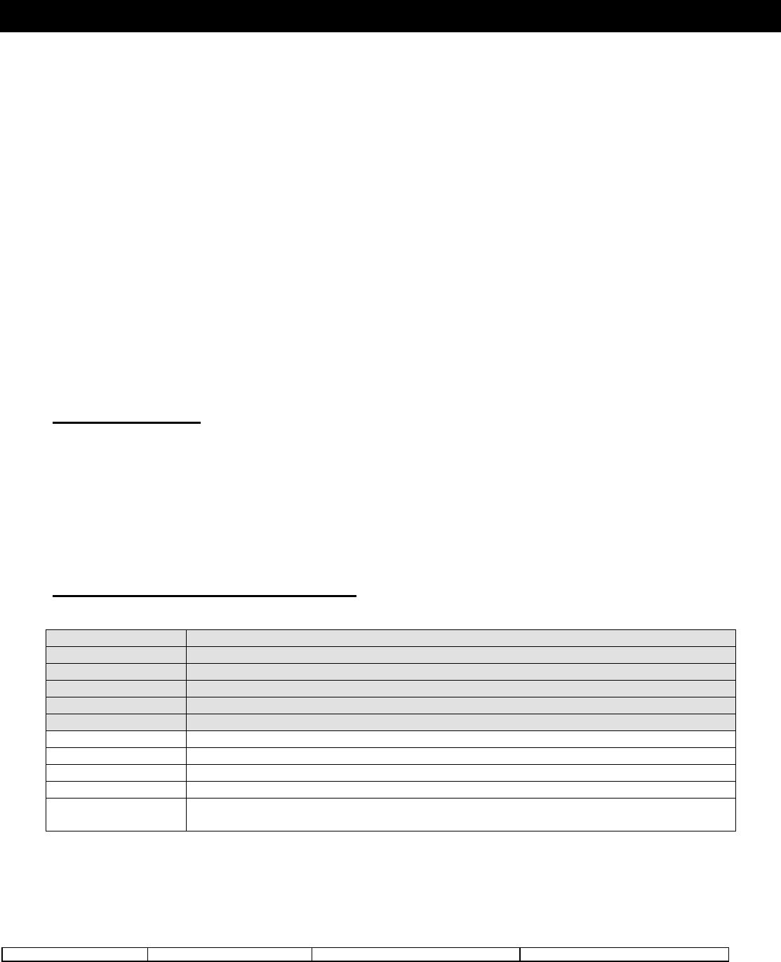
5.2.2.1 Serial Number Programming
Once Installer’s Programming is successfully entered, and the Wizard selection is made, the Installer will be
prompted to enter the Serial Number of their first device. After the number is confirmed, the software will analyze the
number and make the following programming change based off of the Serial Number entered:
Transmitter Type Definition Other
2 (UTX) Define as Delay 1 (Type [01])
3 (Detector) Define as Interior Stay/Away (Type [05])
4 (Smoke) Define as Delayed 24 Hour Fire (Type [87])
5 (Panic Pendant) Define as 24 Hour Panic (Type [16]) Disable Zone Supervision (Section
[804])
Note: this chart is the Programming Actions found in the Wizard Flowchart provided by Marketing.
Hardwired Zone ‘Enrolling’ – The Wizard can also be used to enroll Hardwired zones. Serial Numbers X00001
and X00002 have been reserved for the two on-board zones.
When a zone is enrolled in the Wizard as one of these zones, the WLS9000 will automatically assign the next
available zone number and enter it in Section [020].
For example, if the Installer entered 200001 as the seventh zone, the WLS9000 will assign Zone 7 as being the
first Hardwired zone in Section [20] (first entry 07).
Note: Production must be advised to no longer use X00001 and X00002 as active serial numbers.
5.2.2.2 Zone Label Programming
If an enrolled device is a detector (i.e. not a WLSKey nor HHK), the Wizard will then prompt the Installer to enter
the Zone Label for the newly enrolled zone.
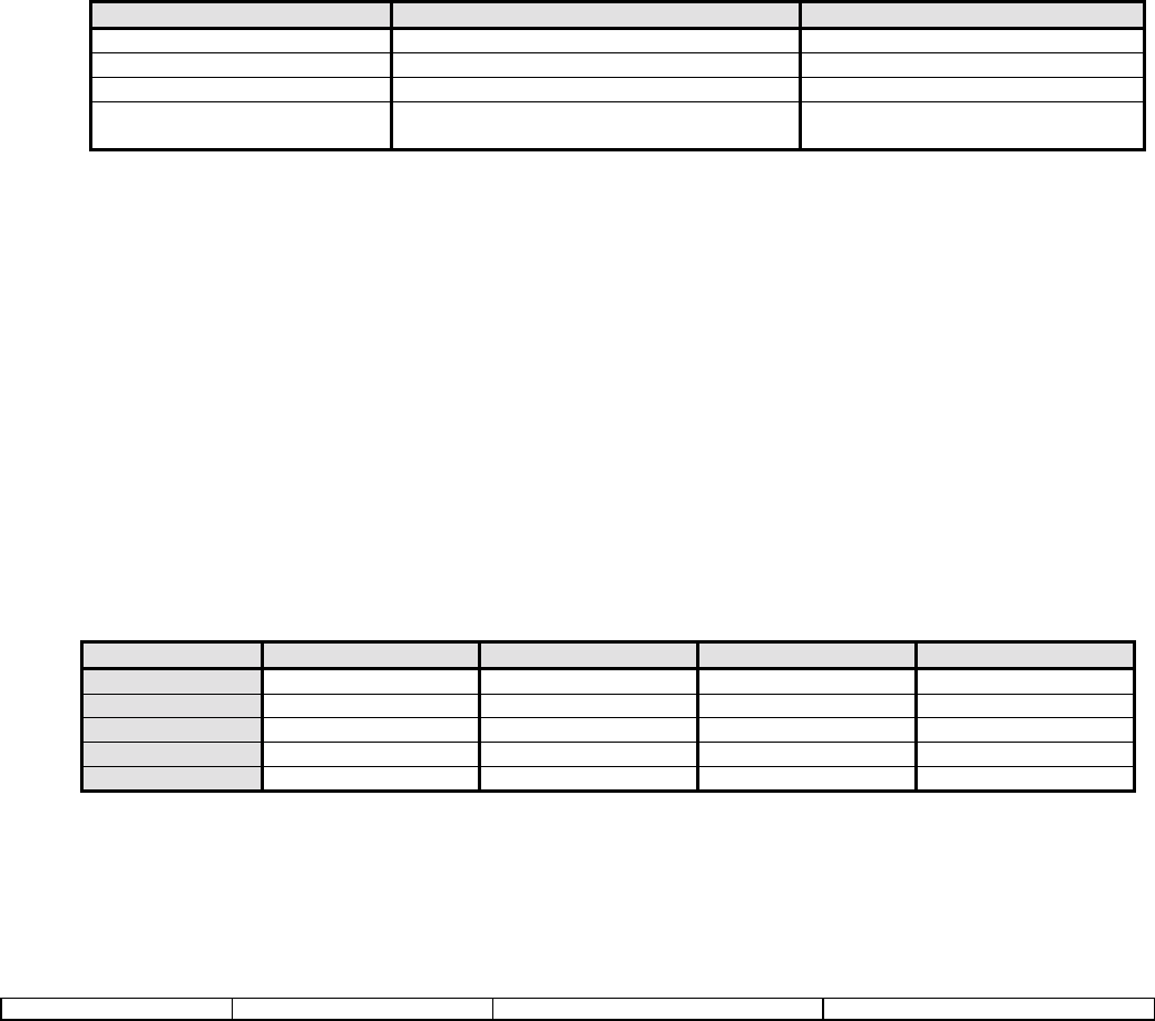
The WLS9000 has five presets for each type of detector programmed that may be selected via pressing the “A” to
“E” keys. Pressing the “F” key will allow the Installer to manually program the label from a chart found in the
manual.
The preset table is as follows:
Selection Type 2 (UTX) Type 3 (Detector) Type 4 (Smoke) Type 5 (Panic Pend)
“A” Preset Front Door Main Floor Motion Main Floor Fire No Presetsv
“B” Preset Back Door Upstairs Motion Upstairs Fire
“C” Preset Garage Door Downstairs Motion Downstairs Fire
“D” Preset Window Hallway Motion Hallway Fire
“E” Preset Patio Door Garage Motion Garage Fire
As soon as a Label is programmed (and confirmed) either via Preset or manual entry, it is immediately stored in
EEPROM.

Digital Security Controls Ltd. 9 Private and Confidential
Installation Manual DATE : 09/30/97 DRAFT
5.2.2.3 Communications Programming
After all of the Serial Numbers have been entered, The Wizard will proceed into Communications Programming.
Here the Installer is prompted for the First Telephone Number and it’s corresponding Account Code. As with all
Wizard Programming, each data entry is followed by a confirmation routine to ensure the data is properly entered.
5.2.2.4 Module Placement Test
The Module Placement Test of the WLS9000 is quite different from previous Power-Based products as it
incorporated the following changes and enhancements:
• Each Detector Must pass three Consecutive Tests before being enabled on the system.
• Each Detector is enabled in Section [202]-[205] only after passing the three tests mentioned above. There is no
way to manually override this enrollment process.
• There are only “Good” and “Bad” Placements. “Fair” has been removed; it’s former status internal to the
software is considered a “Bad”.
• The piezo will squawk once for “Good” and three times for “Bad”.
• If the Placement is exited before all zones are properly enrolled, a General System Trouble is generated at the
keypad. This trouble can only be cleared by re-entering the Module Placement Test and testing the un-enrolled
devices.
• Zones can be disabled via Section [202]-[205], but they cannot be enabled.
When Module Placement Test is entered, the system will annunciate all of the zones which have been enrolled on
the system, but are not enabled in Sections [202]-[205]. This allows the Placement Test to be entered after
additional devices have been enrolled on the system without the hassle or re-testing ‘placed’ zones.
As each device receives three “Good” placements, it is removed from the annunciation list and it’s corresponding bit
in Section [202]-[205] is toggled to enable the zone on the system.
After all zones have passed the Module Placement Test, the Wizard will end and the Installer will find him/herself in
base Standard Programming, where he/she may do additional programming not covered by the Wizard. “#” may be
pressed to exit.
5.2.3 Internal or External Annunciation Selection
A method of selecting either the internal piezo/speaker or external remote sounder for the annunciation of
alarms and Audio has been implemented in the WLS9000. This feature is to deter thieves from “homing in” on the
source of the alarm and tampering with the WLS9000, thus resulting in a potential security breech.
The settings are as follows:
• Local Annunciation (main unit: Section [040] Option 1)
• Remote Annunciation (Remote Sounder: Section [040] Option 2)
• Both (Section [040] Options 1 and 2 ON)
This feature is found in Section [040], Options 1 and 2, with Option 1 defaulted ON and Option 2 defaulted OFF.
5.2.4 Voice Prompting
The WLS9000 will have a complete library of prompts similar to the ESCORT5580 to assist the user through various
functions of the system. This will also include Installer programming prompting similar to ESCORT programming in
the ESCORT5580.
5.2.5 Volume of Annunciation
There is several different levels of volume for the on-board piezos and speaker.
• Full Siren (siren; as loud as possible for alarm conditions)
• Full Voice (speaker; used to verbosely annunciate alarms. Always = highest speaker volume setting)
• Conversational Audio (speaker; Voice Prompted Help = four selectable levels)
• Low “Beeps” (small piezo; trouble conditions)
The volume of the voice prompts may be selected one of two ways:
• Using the Volume Function Key (Type [28]) to toggle through the different volume settings.

Digital Security Controls Ltd. 10 Private and Confidential
Installation Manual DATE : 09/30/97 DRAFT
• Within [*][6] User Programming under selection 7.
5.2.7 Verbal Chime
A feature has been added to the WLS9000 that allows Door Chime to annunciate the Zone that has been
violated/restored as opposed to a series of beeps.
If the Verbal Chime Feature is enabled, whenever a zone with the Chime attribute enabled is violated, a series of
beeps will sound and the WLS9000 will prompt:
“Zone X”
When the zone is restored, the WLS9000 will only sound a series of beeps similar to how Door Chime functions in
our current products.
If a label was programmed for the above Zone, the WLS9000 would annunciate (after the beeps):
“Back Porch Window”
…and so on.
If this option is disabled, only the series of beeps will be heard upon the violation and restore of zones that are
programmed to chime. If Chime is disabled via [*][4], no beeps nor prompts will be heard.
This option can be found in Section [017], Option 2, and is enabled (ON) at default.
5.2.8 Verbal Alarm
A feature has been added to the WLS9000 that provides verbal annunciation of alarm conditions on the system.
When an audible non-fire zone goes into alarm with this feature is enabled, the WLS9000 will sound the alarm
condition via the high volume piezo, but every 5 seconds (as programmed for Alarm Tone Period – Section [807],
Subsection [030])vi it will pause siren and the speaker an annunciate the alarm condition verbally:
“Alarm Zone 4”
or, if the label is programmed,
“Alarm South Bedroom Window”
When the zone is in alarm, the software automatically inserts the word “Alarm” in front of the appropriate zone label.
When an audible fire zone goes into alarm, the WLS9000 will sound the alarm condition via the high volume
piezo, but every 5 seconds (as programmed for Alarm Tone Period – Section [807], Subsection [030]) it
will pause siren and the speaker an annunciate the alarm condition verbally:
“Fire Alarm Zone 4”
or, if the label is programmed,
“Fire Alarm South Bedroom Smoke”
When the zone is in alarm, the WLS9000 automatically inserts the words “Fire” and “Alarm” in front of the
appropriate zone label.
In the case of multiple alarms, the WLS9000 will annunciate the first and latest zone that has gone into alarm.
Fire Zones will override Burglary Zones, similar as a Pulsing Bell will override a steady one.
This option can be found in Section [017], Option 3 and is enabled (ON) at default.
Notes: Fire annunciation always overrides any Burglary Zone alarm annunciation.
Verbal Alarm will cease with the Siren at Bell Time Out.
Digital Security Controls Ltd. 11 Private and Confidential
Installation Manual DATE : 09/30/97 DRAFT
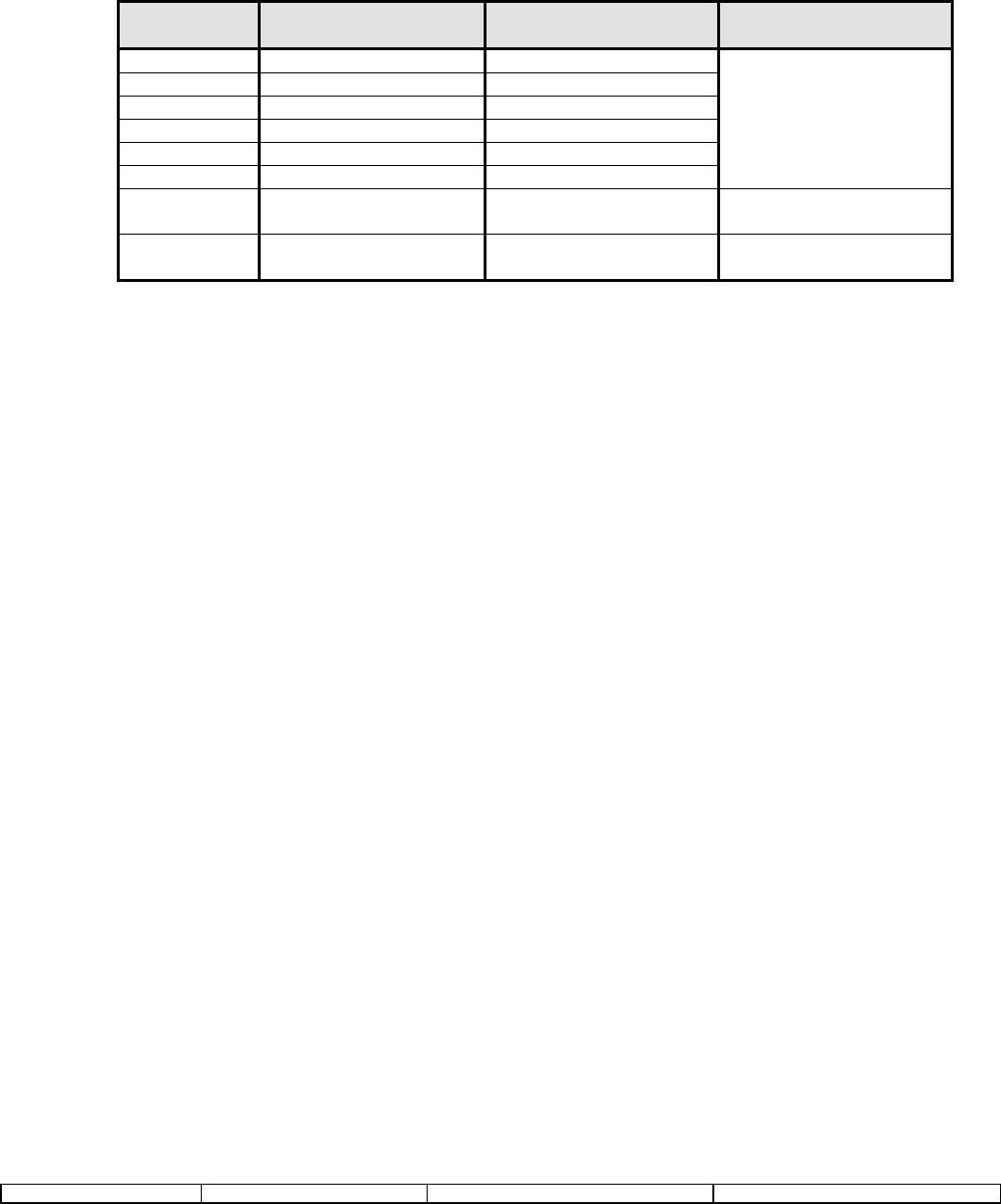
5.2.9 Function Keys While in Installer’s Programming
In order to facilitate a more Installer-friendly user interface, the Eight Function Keys of the WLS9000 will perform
the following functions in Installer’s Programming:
Function
Key Number Default Function Key
Option Installer’s
Programming Function Used For:
1 Stay Hexadecimal ‘A’
2 Away Hexadecimal ‘B’
3 Chime Hexadecimal ‘C’
4 Exit Hexadecimal ‘D’
5 Status Hexadecimal ‘E’
6 Volume Hexadecimal ‘F’
Programming the
corresponding Hex Entry
for Account Codes,
Reporting Codes, Phone
Numbers, etc.
7 Memo Record Forward Moving ahead in the
Programming Wizard.
8 Memo Playback Back Moving backwards in the
Programming Wizard.
• Pressing any key that performs hexadecimal functions will generate a ‘Function Not Available” prompt if the
current section does not support Hex entries.
• The Forward and Back keys are used for:
1. Reviewing and editing previously entered data.
2. Advancing through sections to get to a certain Wizard Section.
Note: Only the Forward Key can be used outside of the Wizard.
5.2.10 Memo Feature
The WLS9000 will have a feature that allows the recording and playback of a verbal memorandum.
A user, while armed or disarmed, can record a memo via the “Memo Record” function key.
To record a memo, press and hold the Memo Record key for two seconds. After the acknowledgement beeps,
speak the desired message in the direction of the WLS9000. When finished, press the “Memo Record” function
key again (note: the two second debounce is not required here).
To hear the last memo recorded, press and hold the “Memo Playback” key for two seconds.
Note: Although the target record duration is 60 seconds, the exact numbers are under development by the
Software department.
5.2.11 Recording of Custom Labels
The WLS9000 has the capability of recording custom labels that may be assigned to a zone like any other
ESCORT Label. Labels [246] to [253] are reserved for Custom Labels 1-8.
These labels can be recorded via Installer’s Programming in Sections [701]-[708] using the following format:
When in Sections [701]-[708], the ‘Record’ key (Function Key 7) may be pressed to begin recording. After the
desired label is verbally annunciated by the Installer, ‘Playback’ (Function Key 8) may be pressed to end the
recording and annunciate the label. ‘Playback’ can be pressed again to re-annunciate the Label
recording.
Notes: Even if Function Keys 7 and 8 have been reprogrammed, they will still retain the same above functions in
these sections.
The quantities and length of the labels recorded will directly affect the total amount of time that a Memo
can be recorded. This is due to the fact as they share the same resources.

Digital Security Controls Ltd. 12 Private and Confidential
Installation Manual DATE : 09/30/97 DRAFT
5.2.13 Function Key Programming in ESCORT Programmingvii
Function Key programming has been moved out of the main panel and into Section [807], Sub-section [000]. This
has been done in order to keep the corresponding programming in the ESCORT section of the product. This
allows the desired functionality to be obtained without major impact to the existing architecture of the software.
5.2.14 New Logsviii
In order to support the new Module Placement functionality, a new log has been implemented for:
Event %1D5 Module Placement Test Unsuccessful
8.0 Functional Description of…
8.1 Standard Features
TWO MINUTE BYPASS ON POWER UP
When power is first applied to the system, all zones will be bypassed for two minutes. This is to allow time for the
devices to “settle” without causing false alarms. If after 2 minutes any zones are still unrestored, they will be
detected as open and will generate the respective alarm sequence, if applicable.
ALARMS ANNUCIATED WHILE ARMED
Zone Alarm conditions will be annunciated on all the WLS9000 by Verbally annunciating them as they occur.
This also occurs for 24 Hour alarms while disarmed.
ACCESS CODE REQUIRED TO CANCEL AUTO ARMING
An access code must be entered to cancel (postpone) the Auto-Arm sequence during the 1-minute Auto-Arm
Warning time.
HARDWIRED ZONE LOOP RESPONSE TIME
The hardwired zone loop response time is fixed at approximately 500ms.
Note: The WLS9000 hardwired zones require a single 5.6K EOL resistor.
TIME-OUTS
The general system time-out for Installers mode is 20 minutes. If the unit is left in Installer’s for twenty minutes
without a keypress, it will return to its base menu.
SILENT EXIT DELAY IF STAY ARMING
If the system Stay armed using any of the following methods, all audible exit features (keypad buzzer) that are
enabled will be silent for the exit delay time. Bell Squawk on Exit Delay will also be silent if Home or [*][9] Armed.
Bell Squawk on Arm/Disarm will still sound regardless of how the panel is armed/disarmed.
[*][9][Access Code]
[Stay Arm Function Key (Option 03)]
[No Entry Arm Function Key (Option 05)]
SPECIAL ENTRY IF ALARM IN MEMORY
If any entry delay begins on the system and there are alarms in memory, the entry tone shall sound a pulsing
tone for the entire entry delay (as per Entry Delay Urgency).
SWINGER SHUTDOWN RESET
If Swinger Shutdown is enabled on the system, all counters will be reset when the system time changes from
23:59 (11:59 PM) to 00:00 (12:00 AM) OR any time the system is armed (expiration of the exit delay).
ENTRY DELAY URGENCY

Digital Security Controls Ltd. 13 Private and Confidential
Installation Manual DATE : 09/30/97 DRAFT
The keypad will sound a steady tone during the Entry Delay. During the last 10 seconds of the Entry Delay, the
keypad buzzer will sound a pulsing tone (3 tones per second) to warn that the Entry Delay is about to expire.
SIREN FOLLOWS SWINGER SHUTDOWN
The siren will not be activated for alarms on zones that have exceeded the limit of alarms set in the Swinger
Shutdown counter.
ROTATING KEYPRESS BUFFER ON DISARM
The WLS9000 has a method to solve the problem of someone entering a code to disarm and getting out of
sequence. The end result of this on other products when the user does not press [#] before re-entering their code is
a false alarm. What the panel does now is look for any 4 digits in a row which match a valid code. If this is deemed
a security risk, Keypad Lockout can be enabled and every fourth or sixth key will count as one bad attempt
depending on the code length. The panel includes this feature while disarmed with the Bell active. This is useful for
audible alarms that may occur in the disarmed state. This feature is hardcoded.
CROSS ZONE POLICE CODE
This event is logged and the reporting code is transmitted to the central station (if enabled) when there are two
different alarms during any armed-to-armed period. This means that if there is one alarm while the panel is armed,
and a second alarm on a different zone after it is disarmed, this code will still be sent. Previous software versions
used to transmit this event for any two different alarms during either an armed or disarmed period, but NOT on a
combination of both.
If two different zones are violated, if both or either have them have the Transmission Delay Attribute enabled, then
the transmission of the Cross Zone Police Code should be delayed for the appropriate time programmed. If neither
of the two zones have Transmission Delay, then the Cross Zone Police Code should be transmitted immediately with
the two zone alarms.
IDENTIFIED WIRELESS KEY ARMING/DISARMING
A method has been developed to identify openings and closings by Wireless Keys. This has been done by relating
each Key to an access code. Wireless Keys 1 to 16 are represented by Access Codes 17 through 32 respectively. If
one of these access codes are programmed via [*][5] programming in the WLS9000, the panel will then log and
transmit the opening/closing by access code, as opposed to opening/closing by keyswitch.
Note: The Function Keys Require Code Option must be on (Section [015], Option 4 OFF) in order for Wireless Keys
to be identified for arming. Disarming will always be logged by access code, if one is programmed for the Key,
regardless of this option.
PANIC PENDANT TEST
When a Pendant Test is executed, the WLS9000 will sound a steady 1 second tone.
Note: the LED update is not kept up for the duration of the test. The WLS9000 will not be returned to the ready state
for 30 seconds or when the “#” key is pressed.
ONE TIME RESTART OF EXIT DELAY
A hardcoded feature has been implemented that allows a single restart of the exit delay with the press of the
Away key during the Exit Delay. This feature will not be permitted if Arming With No Entry ([*][9]) or with the Stay
key.
HARDWARE DEFAULTix
The WLS9000 may be defaulted via hardware by shorting the Remote Sounder Data Terminal (Green) to Black. The
short must be present for 1 second on power-up for the system to properly default.
Note: This only defaults the main controller. All other defaulting must be done individually through Installer’s
Programming.
8.2 Feature Set

Digital Security Controls Ltd. 14 Private and Confidential
Installation Manual DATE : 09/30/97 DRAFT
8.2.1 Zone Definitions [001]-[004]
Each of these sections require 8 two digit entries. Each two digit number entered describes how a zone will
operate.
00 Null Zone is for zones that are not used and does not require a closed loop or EOL resistor
01 Delay 1 follows the Entry Delay 1 and Exit Delay programmed in Section [005] and is normally used for
Entry/Exit doors. The exit delay starts as soon as the panel is armed. The zone may be opened and
closed during the delay time without causing an alarm. After the exit delay time has expired, opening
the zone will start the Entry Delay timer. During the Entry Delay time, the keypad buzzer will sound
steadily to advise the user that the system should be disarmed. If the panel is disarmed before the Entry
Delay expires, no alarm will be generated.
02 Delay 2 operates the same as Type [01] zone except the Entry Delay time can be independently set in
Section [005]. The Exit Delay time is common to both zone types.
03 Instant is normally used for door and window contacts and has the standard Exit Delay, but is instant when
opened after the Exit Delay expires.
04 Interior are used with interior motion detectors. Interior zones feature both an Exit Delay and an Entry Delay
provided that any Delay type zone has been tripped first. If the protected area is entered without coming
through the a delayed entrance and an Interior zone is tripped, an immediate alarm will be generated.
05 Interior Stay/Away. If the system is armed and a Delay zone is NOT tripped during the exit delay time,
this zone type will be bypassed. If the [*][1] command is used to activate all Stay/Away type zones,
this zone will have the standard exit delay. Once armed, this zone will act like an Interior type zone [04].
06 Delay Stay/Away If the system is armed and a Delay zone is NOT tripped during the exit delay time,
this zone type will be bypassed. If the [*][1] command is used to activate all Stay/Away type zones,
this zone will have the standard exit delay. Once armed, this zone will always have follow the Entry Delay
time for Entry Delay 1 when tripped.
Note: The automatic bypass on Stay/Away type zones will not be removed by any event other
than a valid exit through a Delay type 1 zone during the exit delay or by pressing [*][1] while
armed.
07-08 Not Used x
10 24 Hour Supervisory Buzzer is active at all times and will report an alarm at all times. Once tripped, the
keypad buzzer will sound until a valid access code is entered. If configured for Global operation, an
access code will be required on each partition to silence the buzzer on the corresponding partition.
Note: This zone type should not be used on a Keyswitch ONLY system.
11 24 Hour Burglary is active at all times and will report an alarm if the panel is armed or disarmed. This type
will sound the bell for the length of Bell cutoff if the audible attribute is enabled.
12 24 Hour Holdup is similar to 24 Hour Burglary except for System Event output type and SIA identifier.
13 24 Hour Gas is similar to 24 Hour Burglary except for System Event output type and SIA identifier.
14 24 Hour Heat is similar to 24 Hour Burglary except for System Event output type and SIA identifier.
15 24 Hour Medical is similar to 24 Hour Burglary except for System Event output type and SIA identifier.
16 24 Hour Panic is similar to 24 Hour Burglary except for System Event output type and SIA identifier.

Digital Security Controls Ltd. 15 Private and Confidential
Installation Manual DATE : 09/30/97 DRAFT
17 24 Hour Emergency is similar to 24 Hour Burglary except for System Event output type and SIA identifier.
18 24 Hour Sprinkler is similar to 24 Hour Burglary except for System Event output type and SIA identifier.
19 24 Hour Water is similar to 24 Hour Burglary except for System Event output type and SIA identifier.
20 24 Hour Freeze is similar to 24 Hour Burglary except for System Event output type and SIA identifier.
21 24 Hour Latching Tamper. This zone type, when violated, will cause arming of the system (both partitions)
to be inhibited until the valid Installer code is entered. If this zone type is violated, the Installers code
must be entered ([*][8] Installers Code) before the system can be armed.
22 Momentary Keyswitch Arm. A keyswitch module may be connected to the zone programmed as
Momentary Keyswitch arm. Momentary activation of this zone will alternatively arm and disarm the
system and silence alarms. Note that the keypad will not display an indication when this type of zone is
activated.
23 Maintained Keyswitch Arm. A Normally Open Keyswitch module may be connected to the zone
programmed as Maintained Keyswitch arm. In the restored state, the panel is disarmed. Any violation of
the zone will cause the system to arm (Alarm, Tamper, Fault).
24-26 Not Used
87 Delayed 24 Hour Fire (Wireless) works the same way as the Standard fire zone, except the alarm
memory and transmission by the communicator is delayed by 30 seconds. If the alarm is acknowledged
by pressing any key within 30 seconds, the bells will silence and the transmission will be aborted. If after
the alarm has been acknowledged, and the smoke detector has not been restored to normal, after 90
seconds the bell output will be activated again, in which the user then has another 30 second delay before
the bell output latches and communications is activated. A code would then be required to silence the bell
output.
Note: The Fire Delay will be terminated if a 2nd Fire zone is tripped or if the [F] key is pressed during a
delay.
88 Standard 24 Hour Fire (Wireless) is a fire zone that is specially used for pull station type circuits. On
alarm, the bell output will sound to indicate that the fire loop has been activated. If enabled, the
communicator will immediately transmit the alarm to the monitoring station.
Note: For all Fire type zones the Zone Attributes should not be changed from the default
settings.
8.2.2 System Times [005]
This section requires 4 three digit entries.
Note: Entry of 000 in these sections will result in 255 second times.
Entry Delay 1: (001-255) Seconds
This value determines the Entry delay time for Delay 1 type zones. The default Entry
Delay 1 time is 30 seconds.
Entry Delay 2: (001-255) Seconds
This value determines the Entry delay time for Delay 2 type zones. The default Entry
Delay 2 time is 45 seconds.
Exit Delay: (001-255) Seconds

Digital Security Controls Ltd. 16 Private and Confidential
Installation Manual DATE : 09/30/97 DRAFT
The system will use one common exit delay time that must be programmed to accommodate the
longest possible exit time required. The default Exit delay time is 120 seconds.
Bell Cut-off: (001-255) Minutes
This value determines the time the bell / siren will sound before automatically turning off. The default bell
cutoff time is 4 minutes.
Alarms/Events which cause the Keypad Buzzer to sound (System Tampers, 24 Hour Buzzer Zone, etc)
do not follow this Bell Cutoff Timer. The buzzer will sound until an access code is entered to silence the
condition.
8.2.3 Special Access Codes [006]-[008]
Each of these sections require 4 or 6 digits to be entered.
Installer’s Code.
Master Code.
Maintenance Code. This is a Arm/Disarm only code. It can not be used to bypass program other user
codes or enter the [*][6] menu. Openings or Closings using this code report as a Special Opening/Closing
and will log to the event buffer as “Maintenance Code”.
8.2.4 Keypad Lockout Options [012]
This section determines how the keypad lockout function operates.
Number of Invalid Codes Before Lockout
Program a number from 000 to 255 to determine the number of invalid master, duress, user or installer
access code entries to reach keypad lockout. When keypad lockout occurs, the system is rendered
inoperative via keypad for the programmed duration. When any keys are pressed, an error tone will
sound. Entering 000 disables the feature.
Lockout Duration
Program a time from 000 to 255 minutes to determine the length of time before lockout resets and the
keypad can once again be used.
Note: If lockout is not reached within the hour roll-over, the number of invalid attempts is reset
to 0.
FAP keys are still active during Keypad Lockout.
8.2.5 System Options Codes
[013] First System Options Code
[1] Hardwired Zone Supervision Option
ON = Hardwired Zones are EOL
Both hardwired zone loops on the WLS9000 use EOL supervision.
OFF = Hardwired Zones are Normally Closed
Both hardwired zone loops on the WLS9000 use Normally Closed loops.
[2]-[3] Not Used
[4] Tampers/Faults Annunciation Option
ON = Tampers and Faults Do Not Annunciate as Open
The panel will not annunciate the respective Zone if the zone is in the Tamper or Fault states,

Digital Security Controls Ltd. 17 Private and Confidential
Installation Manual DATE : 09/30/97 DRAFT
only the Trouble LED will be on.
OFF = Tampers and Faults Annunciate as Open
The panel will annunciate the respective Zone if the zone is in the Tamper or Fault states.
The Trouble LED will also be lit.
[5] Not Used
[6] Audible Exit Fault Option
ON = Audible Exit Fault is Enabled.
If a non force-armable Delay 1 or Delay 2 type zone is left open at the end of the Exit Delay, the
Entry Delay will begin immediately and the bell or siren will sound a steady alarm for the time
programmed as Bell Timeout. This feature is designed to immediately alert the user that their
system has been armed incorrectly.
OFF = Audible Exit Fault is Disabled.
Note: For [*][9] arming, if Audible Exit Fault is enabled a violated zone will begin entry delay as
per Audible Exit Fault functionality. If this option is disabled, a violated delay zone at the end of
the exit delay will cause an instant alarm.
[7] Event Buffer Swinger Options
ON = Event Buffer Follows Swinger Shutdown.
Once an event reaches its Swinger Shutdown limit programmed in Section [370], it will no longer
log to the Event Buffer until the Swinger Shutdown is reset. This avoids filling the Event Buffer
with useless events.
OFF = Event Buffer Logs Events past Swinger Shutdown.
[8] Fire Signaling Options
ON = Temporal Three Fire Signal.
In order to comply fully with NFPA 72, all Fire Bells will sound in the Temporal Three Pattern as
described in the NFPA standard if this option is enabled. This cadence is as follows: 500ms ON,
500ms OFF, 500ms ON, 500ms OFF, 500ms ON, 1.5 s OFF.
OFF = Standard Pulsed Fire Signal.
All fire bells will sound with the standard 1 second on/1 second off fire bell cadence.
[014] Second System Options Code
[1] Bell Squawk Options
ON = Arm / Disarm Bell Squawk Enabled.
The Bell output will sound a single squawk when armed in any manner, incl Auto-arm, and a
double squawk upon disarming the system. If there are alarms in memory, the bell will emit a series
of three squawk pairs to indicate the alarm memory.
OFF = Arm / Disarm Bell Squawk Disabled.
The Bell output will not squawk when the system is armed or disarmed in any manner.
[2] Bell During Auto-Arm Options
ON = Bell Squawk During Auto-Arm Enabled.
The Bell output will sound a single squawk every 10 seconds during the 1 minute Auto-Arm Pre-
alert time.
OFF = Bell Squawk During Auto-Arm Disabled.
The Bell output will not be activated during the 1-minute Auto-Arm warning time.
[3] Bell Squawk On Exit Options
ON = Bell Squawk On Exit Delay.
The Bell output will squawk once per second during the Exit Delay time. The bell will also sound
3 squawks per second for the final 10 seconds.
OFF = No Bell Squawk On Exit Delay.
Note: This audible option applies to ALL manual arming modes (Stay, Away, No Entry, etc)

Digital Security Controls Ltd. 18 Private and Confidential
Installation Manual DATE : 09/30/97 DRAFT
[4] Bell Squawk On Entry Options
ON = Bell Squawk On Entry Delay.
The Bell output will pulse with the same timing as the keypad buzzer during the Entry Delay time.
The bell will sound 3 squawks per second for the final 10 seconds if Option 6 in this section is
enabled.
OFF = No Bell Squawk On Entry Delay.
[5] Bell Squawk on Trouble Options
ON = Bell Squawks on Trouble.
Whenever there is a Trouble condition enunciated on the system keypads, the Bell will squawk 2
times every 10 seconds (as per the keypad buzzer). The Bell will be silenced when the keypad
beeps are silenced (any key pressed on keypad).
OFF = No Bell Squawks on Trouble.
[6] Audible Exit Beeps
ON = Audible Exit With Urgency.
The keypad will sound a pulsing tone (once per second) during the Exit Delay. For the last 10
seconds of the Exit Delay, the keypad and bell / siren (if enabled) will sound a different tone (3 tones
per second) to warn that the Exit Delay is about to expire.
OFF = Silent Exit Delay.
The keypad will not sound during the Exit Delay.
[7] Exit Delay Termination Options
ON = Exit Delay Termination Enabled.
The Exit Delay will be terminated once a Delay 1 Zone for the entry/exit door or area is restored. All
audible options associated with the exit delay will be silenced when the Exit Delay is terminated.
Force-Armable Delay 1 type zones will also terminate the exit delay.
OFF = Exit Delay Termination Disabled.
The Exit Delay timer will continue to count even after the Delay Zone for the entry/exit door or area is
restored. All audible options associated with the Exit Delay will function until the time programmed
for the Exit Delay has elapsed.
[8] Fire Bell Timeout Options
ON = Fire Bell is Continuous.
For all Fire type alarms, the Bell output will sound until an access code is entered to silence the
alarm or disarm the system regardless of the time programmed for Bell Timeout in Section [005].
OFF = Fire Bell Follows Timeout.
For all Fire type alarms, the Bell output will sound for the length of Bell timeout or until an access
code is entered.
[015] Third System Options Code
[1] [F] Key Options
ON = [F] Key Enabled.
Pressing and holding the [F] keys for 2 seconds will generate a Fire alarm. The keypad will sound a
set of 3 beeps to acknowledge the valid alarm and the bell or siren will sound with a pulsing tone for
the length of Bell time-out. An alarm reporting code (if programmed) will be transmitted.
OFF = [F] Key Disabled.
The [F] key will not sound or report an alarm when pressed.
[2] [P] Key Annunciation Options
ON = [P] Key Audible.
When a valid [P] key alarm is generated, the Keypad buzzer will sound a series
of 3 beeps to acknowledge the alarm and the bell or siren will sound for the length of Bell timeout.
OFF = [P] Key Silent.

Digital Security Controls Ltd. 19 Private and Confidential
Installation Manual DATE : 09/30/97 DRAFT
When a valid [P] key alarm is generated, the Keypad buzzer and the bell output will remain silent,
but the alarm transmission will still be transmitted (if programmed).
[3] Quick Exit Options
ON = Quick Exit Enabled.
When the system is armed, users may enter the [*][0] Command to allow a single Delay 1 or Delay 2
Zone to be activated so they may leave the premises. Only one Delay zone may be activated; any
additional activity on another Delay zone will cause its respective alarm sequence. If the Delay zone
is still open two minutes after the [*][0] command is entered, the Entry Delay will be initiated. If
armed in the Stay mode, the automatic bypass on Stay/Away zones will not be removed.
OFF = Quick Exit Disabled.
[4] Quick Arming/Function Key Options
ON = Quick Arming Enabled/Function Keys Do Not Require Code.
[*][0] arming and Stay/Away Function Keys may be used to arm the system without the
entry of a valid access code. All other function Keys may also be used without the entry of an
access code.
OFF = Quick Arming Disabled/Function Keys Require Code.
[*][0] arming is not permitted, and all Function Keys require the entry of an access code to
activate (including Stay/Away keys).
[5] Bypass Access Code Options
ON = Access Code Required to Bypass Zones.
After entering the [*][1] Bypass Zones Command, an access code must be entered before zones
may be bypassed.
OFF = Access Code Not Required to Bypass Zones.
Enter the [*][1] Bypass Zones Command to bypass zones.
Note: this option is supplemental to Option 4.
[6] Master Code Options
ON = Master Code Not User Changeable.
The Master Code (Access Code 40) may not be changed by the user, and may only be programmed
in the Installer’s Programming Mode.
OFF = Master Code User-Changeable.
The Master Code (#40) may be programmed by the user using the [*][5][Master Code] command.
The Master Code may also be programmed in the Installer’s Programming Mode.
[7] Telephone Line Monitor Options
ON = Telephone Line Monitor enabled.
The TLM function will be active and the system will indicate a Trouble #3 condition when using the
[*][2] View Trouble Conditions Command.
OFF = Telephone Line Monitor disabled.
The TLM function will be shut off and telephone line troubles will not be indicated by the system.
[8] Telephone Line Monitor Trouble Options
ON = TLM Audible When Armed.
When the system is disarmed, a telephone line monitor trouble will generate a trouble indication as
described above. If the system is armed, a telephone line monitor trouble will generate an audible
alarm on the bell or siren for the duration programmed for Bell Timeout or until an access code is
entered to disarm.
OFF = TLM Trouble Only.
A telephone line trouble will generate a trouble indication, the Trouble LED will come ON and the
keypad sounder will beep until a key is pressed.
[016] Fourth System Options Code

Digital Security Controls Ltd. 20 Private and Confidential
Installation Manual DATE : 09/30/97 DRAFT
[1]-[2] Not Used
[3] Blanking Options
ON = Blank WLS9000 When Not Used.
If no keys are pressed for 30 seconds, all on board lights except backlighting (if enabled) will be shut
OFF until the next keypress, Entry delay, Audible Alarm or keypad buzzer condition.
OFF = WLS9000 Always Active.
The on-board lights will remain ON at all times.
[4] Blanking Restore Options
ON = Access Code Required to remove WLS9000 Blanking.
Before a blanked WLS9000 can be used, a valid access code must be entered.
OFF = Access Code Not Required.
Pressing any key on a WLS9000 will remove the blanking.
[5] Backlighting Options
ON = Backlighting is Enabled.
The system will have backlighting on all of the time.
OFF = Backlighting is Disabled.
[6] Not Used
[7] Bypass Status Display Options
ON = Bypass Status Displayed While Armed.
The Bypass status light will be ON if there are zones bypassed when the system is armed.
OFF = Bypass Status Not Displayed While Armed.
The Bypass light will be ON only while the system is disarmed to indicate that there are bypassed
zones on the system. When the system is armed, the Bypass light will be OFF.
Note: The Bypass status LED will be ON if there are Stay/Away zones auto bypassed at the time
of arming regardless of whether or not this option is enabled. This option only enables and
disables manual bypass display.
[8] Not Used
[017] Fifth System Options Code
[1] WLSKey Disarming Options
A toggle option has been added to prohibit the use the Disarm key on an unidentified Wireless Key.
ON = WLSKeys Does Not Use Access Codes.
The WLS9000 will accept the disarm keycode from an unidentified Wireless Key, thereby allowing
arming/disarming without a code.
OFF = WLSKeys Uses Access Codes.
The WLS9000 will NOT accept the disarm keycode from an unidentified Wireless Key, thereby an
access code must be associated to a WKEY for proper operation.
[2] Verbal Door Chime Option
ON = Verbal Door Chime is Enabled.
The WLS9000 will verbally annunciate the zone (or programmed label) when it is either
violated or restored if Door Chime is programmed.
OFF = Verbal Door Chime is Disabled.
The WLS9000 will only annunciate a series of beeps whenever a zone programmed for Chime
is either violated or restored.

Digital Security Controls Ltd. 21 Private and Confidential
Installation Manual DATE : 09/30/97 DRAFT
This option is defaulted ON.
[3] Verbal Alarm Option
ON = Verbal Alarm is Enabled.
The WLS9000 will verbally annunciate audible zone alarms via their zone number (or programmed
label) in conjunction with the high volume piezo.
OFF = Verbal Alarm is Disabled.
The WLS9000 will only annunciate the high volume piezo during an audible alarm condition.
This option is defaulted ON.
[4]-[7] Not Used
[8] Bell Squawk on Away Arming Option
ON = Bell Squawk on Away Arming/Disarming Only
Bell Squawks will only be annunciated on Away Arming, as well as upon Disarming after being ared
in the Away Mode.
OFF = Bell Squawk on All Arming/Disarming
Bell Squawks will be annunciated on all types of Arming and Disarming (if programmed in Section
[014]).
This feature is defaulted OFF.
Notes: This feature is to prevent the Bell from being activated when arming from inside the premises.
This option follows the “Bell Squawk on Arming/Disarming” and “Bell Squawk Attribute” features.
8.2.6 Hardwired Zone Assignment [804] Subsections [71] and [72]xi
This section determines which zone number corresponds to the Hardwired zones found on the main unit.
Enter the 2 digit zone number to be designated for each loop.
Please note that this section has moved to Sections [71] and [72] of the RF Slave (Section [804]).
Default
[71] Hardwired Zone Loop #1 Assignment 00 I___II___I (Valid entries are Zones 01-32)
[72] Hardwired Zone Loop #2 Assignment 00 I___II___I
8.2.7 Remote/Local Annunciation Options (Section [017] Options 4 and 5)xii
New toggle options have been added in Section [017] has been added to the WLS9000 that allows the Installer to
have alarm/audio annunciation at the Local Unit, Remote Sounder, or both.
[4] Local Annunciation
ON = Annunciation Sounds Locally
All Audio and alarm annunciation is emitted from the main WLS9000 unit.
OFF = Annunciation Does Not Sound Locally
No alarm or audio annunciation is emitted from the main unit.
This Option is defaulted ON.
[5] Remote Annunciation
ON = Annunciation Sounds Remotely
All Audio and alarm annunciation is emitted from the Remote Sounder.
OFF = Annunciation Does Not Sound Remotely
No audio and alarm annunciation is emitted from the Remote Sounder.
This option is defaulted OFF.
8.2.8 Zone Attributes [101]-[132]
The following options can be enabled or disabled by zone.

Digital Security Controls Ltd. 22 Private and Confidential
Installation Manual DATE : 09/30/97 DRAFT
[1] Bell Options
ON = An alarm causes the bell output to activate.
OFF = Silent Alarm.
[2] Bell Type
ON = The bell output will be steady when the zone is in alarm.
OFF = The bell output will pulse when the zone is in alarm.
[3] Chime Options
ON = The WLS9000 will chime both when the zone is violated and when the zone is
secured. Door Chime will work in both the armed and disarmed states.
OFF = The zone will not chime the keypads.
[4] Bypass Options
ON = The zone may be manually bypassed.
OFF = The zone cannot be bypassed.
[5] Force Arming Options
ON = The system may be armed with the zone violated. The zone will be temporarily
bypassed, and when the zone is secured it will be added back into the system.
OFF = The partition cannot be armed if this zone is open.
[6] Swinger Shutdown Options
ON = After the zone causes a programmed number of alarms, the zone will shut down so that no further
transmissions are sent to the monitoring station. The bell can follow Swinger Shutdown if
programmed.
OFF = Swinger Shutdown disabled
[7] Transmission Delay Options
ON = The reporting of zone alarms will be delayed for the programmed time. If a valid access code is
entered within this time, no alarm signal will be communicated.
OFF = When an alarm occurs, the reporting code is transmitted immediately.
[8] Wireless Option
ON = Zone is Wireless.
All Zones on the WLS9000 are wireless with the exception of the two Hardwired loops. Enabled is
the default condition of all Zone Definitions
OFF = Not Usedxiii
Note: Fire Zones attributes should not be changed. They should remain as defined by the
default settings.
[160] Maximum Dialing Attempts To Each Phone Number
This value represents the number of attempts that will be made to each telephone number when communicating.
The default value is 008 attempts. Valid entries are 001-015.
[161] Post Dial Wait For Handshake
This value represents the time the communicator waits for a valid initial handshake from the receiver after dialing
the programmed telephone number. The default value is 040 seconds.
[202]-[205] System Zone Assignments
These eight bit toggle section determines which zones on the system are enabled. All zones that are enabled will

Digital Security Controls Ltd. 23 Private and Confidential
Installation Manual DATE : 09/30/97 DRAFT
be supervised via the panel’s EOL supervision, and will operate according to the zone type programmed. If a zone is
disabled, it will not be supervised and all activity on the zone will be ignored by the panel.
8.2.9 Telephone Numbers
[301] First Telephone Number
[302] Second Telephone Number
[303] Third Telephone Number
All telephone numbers are 32 digits in length.
Hexadecimal digits may be programmed in the telephone number to perform certain functions.
Enter [*2*] - HEX B to dial “*”
Enter [*3*] - HEX C to dial “#”
Enter [*4*] - HEX D for an additional dial tone search, as is required for PBX telephone systems.
Enter [*5*] - HEX E to insert a 2 Second Pause in the telephone number.
Notes: -There is a static delay of 2 seconds before any additional dialtone search in a phone number.
-HEX A is not used; HEX F represents the end of the Phone Number (everything after F is ignored)
-In order to comply with European PTT specification requirements, the panel will not attempt to
communicate, if no phone number is programmed. This applies to Phone Numbers 1 and 2.
[310] Telephone Number 1/3 Account Code
This is the Account Code used by the panel when communicating via Phone Numbers 1 and 3.
[311] Telephone Number 2 Account Code
This is the Account Code used by the panel when communicating via Phone Number 2.
Note: Both Account Codes are 4 digits in length. Valid entries are 0000-FFFE.
8.2.10 Reporting Codes
Zone Alarms & Alarm Restorals
These reporting codes are used by the communicator to transmit zone alarms and restorals for zones 1
to 32.
These reporting codes are sent to the Alarm & Restoral call direction group.
Duress Alarm
This reporting code will be transmitted to the monitoring station whenever either Duress code is used to
perform any function on the system.
This reporting code is sent to the Alarm & Restoral call direction group.
Opening After Alarm
If programmed, this reporting code will be transmitted to the monitoring station on Opening if an alarm
occurred during the previous armed period.
This reporting code is sent to the Alarm & Restoral call direction group of the System.
Recent Closing

Digital Security Controls Ltd. 24 Private and Confidential
Installation Manual DATE : 09/30/97 DRAFT
A Recent Closing transmission shall be sent if an alarm occurs within 2 minutes of an exit time
expiration. The Recent Closing report will be sent for the first alarm only.
This reporting code is sent to the Alarm & Restoral call direction group of the System.
[F], [A], [P] Alarms & Restorals
If enabled, these reporting codes will be sent if the keys are used to generate manual alarms.
These reporting codes are sent to the Alarm & Restoral call direction group of Partition 1.
Zone Tampers & Tamper Restorals
These reporting codes are used by the communicator to transmit zone tampers and restorals for zones 1
to 32.
These reporting codes are sent to the system Tamper Alarm & Tamper Restoral call direction group of
the System.
Keypad Lockout
This reporting code is sent whenever the System enters Keypad Lockout.
This reporting code is sent to the system Tamper Alarm & Tamper Restoral call direction group of the
System.
Closing by Users 1-32, 40, 41, 42
A closing by any of these access codes will result in transmission of the corresponding reporting code.
These reporting codes are sent to the Opening and Closing call direction group of the System. This
software version will log either “Armed in Stay Mode” or “Armed in Away Mode” for this closing type.
Closing by Users 33 & 34 (Duress)
Similarly, a closing by these access codes will result in transmission of the corresponding reporting code.
These reporting codes are sent to the Opening and Closing call direction group of the System.
See also Duress Alarm Reporting Code.
Partial Closing
If programmed, this reporting code will be transmitted to the Central Station with the Closing code if there
were zones manually bypassed at the time of arming to warn of a security compromise. Automatic
bypasses caused by Stay Arming will not cause this code to be transmitted. Zones force armed by
Automatic Arming will transmit in the manner described above. If SIA is used, each zone will be
identified using the UB-XX (Untyped Bypass) identifier. The identified zones will follow the partial closing
code and precede the closing transmission.
Special Closing
If the system is closed (armed) using any of the following methods, this reporting code will be
transmitted.
Maintenance Code, Keyswitch Zone, Downloading, Quick Arm (*0), Auto Arming. This software version
will also log either “Armed in Stay Mode” or “Armed in Away Mode” for all closing types.
Opening by Users 1-32, 40, 41, 42
An opening by any of these access codes will result in transmission of the corresponding reporting code.
These reporting codes are sent to the Opening and Closing call direction group of the System.
Opening by Users 33 & 34 (Duress)
Similarly, an opening by these access codes will result in transmission of the corresponding reporting
code.
These reporting codes are sent to the Opening and Closing call direction group of the System.
See also Duress Alarm Reporting Code.
Auto Arm Cancellation

Digital Security Controls Ltd. 25 Private and Confidential
Installation Manual DATE : 09/30/97 DRAFT
This reporting code is transmitted when the Auto Arming sequence is canceled. Cancellation of the
sequence can be achieved by entering an access code (if required), activating a keyswitch zone input,
or by pressing the ‘Disarm’ Key on a WLSKey during the 1 minute pre-alert.
Special Opening
If the system is opened (disarmed) using any of the following methods, this reporting code will be
transmitted. (Maintenance Code, Keyswitch Zone (WLSKey), or Downloading).
Battery Trouble & Restoral
If the standby battery is low or disconnected, this trouble will be reported.
These reporting codes are sent to the System Maintenance Call Direction Group.
AC Failure & Restoral
If the AC supply has failed or has been restored, these reporting codes will be sent. There is a
programmable delay (001-255 minutes) which applies to both the trouble and the restoral.
These reporting codes are sent to the System Maintenance Call Direction Group.
Remote Sounder Trouble & Restoral
If the WLS9000 does not receive a supervisiory signal for ten seconds, this trouble condition will be logged
and communicated.
These reporting codes are sent to the System Maintenance Call Direction Group.
Fire Trouble & Restoral
An open circuit on any Fire Zone or the 2 wire smoke circuit will cause this trouble to be reported.
These reporting codes are sent to the System Maintenance Call Direction Group.
TLM Restoral
The TLM Restoral code is sent when the telephone line is restored from the trouble condition.
These reporting codes are sent to the System Maintenance Call Direction Group.
Failure to Communicate (Phone Numbers 1 & 2)
When events fail to communicate to either telephone number, this reporting code will be transmitted the
next time a communication is successful. The information will be transmitted in the following order.
OLD EVENT(S)
FAILURE TO COMMUNICATE (PHONE #1)
NEW EVENT(S)
If multiple FTC’s occur this FTC reporting code will create blocks of old information.
The FTC reporting code does not follow any call direction “group”. It is sent to every group’s call
directions upon transmissions of failed event transmissions.
When event(s) fail to communicate to a telephone number, there will not be an attempt to communicate
again until another event is sent to that phone number.
Event Buffer is 75% Full Since Last Upload
Whenever the 128 event internal buffer has reached a level of 75% full since the last successful upload
from a downloading computer, this reporting code will be transmitted.
This reporting code is sent to the System Maintenance Call Direction Group.
DLS Lead In and Lead Out
The DLS Lead Out Reporting codes will be transmitted by the panel every time DLS has completed a
successful DLS call to the panel. The DLS Lead In reporting code is transmitted two ways: after the
panel has been successfully called by DLS, but before the panel calls DLS back via the Downloading
Telephone Number when Callback is enabled; or upon a User Initiated Call-up.
These reporting codes are sent to the System Maintenance Call Direction Group with the System
identifier.
Zone Fault & Restoral
This reporting code is sent whenever a zone has entered the Fault state via a loss of supervisory on a

Digital Security Controls Ltd. 26 Private and Confidential
Installation Manual DATE : 09/30/97 DRAFT
wireless zone. These reporting codes are sent to the System Maintenance Call Direction Group.
Periodic Test Transmission
When the programmed interval and time of day have elapsed, this reporting code will be transmitted to
the central monitoring station. This reporting code is sent to the System Test Transmission Call
Direction Group.
System Test
When the [*][6][Master Code][4] command is used to perform a manual system test, this reporting code
is sent to test the communicator. This reporting code is sent to the System Test Transmission Call
Direction Group.
Wireless Maintenance Reporting Codes
The following reporting codes are sent to report a Low Battery condition on the system. Individual zones
are not described using the Pulse formats however the individual zones will be logged to the event
buffer. SIA and Contact I.D. formats will identify the zone with the condition.
General Zone Low Battery Alarm and Restore Codes
A low battery alarm occurs when the system component’s battery voltage supply drops below 3.3 (3.5)
Volts. A zone trouble will be displayed immediately but the transmission may be delayed (see Section
[370]). A low battery restoral may only take place after the alarm sensing device has been tampered and
the batteries have been changed. These reporting codes are transmitted to the System Maintenance
Call Direction group.
8.2.11 Communicator Format Options [360]
This section requires 2 two digit entries (1 per phone number). The 3rd telephone number uses the format programmed for
the 1st telephone number.
01 20 BPS, 1400 HZ handshake
02 20 BPS, 2300 HZ handshake
03 CONTACT I.D.
04 SIA FSK
05 Pager
REPORTING CODES
SIA - 0 is valid in Account or Rep Code (not 00 in a Reporting code though)
ADEMCO Contact ID - 0 is not valid in Account or Rep Code (A must be used, 10 in checksum)
BPS Formats - 0 is not valid in Account or Rep Code (A must be used)
SIA
This format uses 300 Baud FSK as the communication media.
The Account Codes must be 4 hexidecimal digits in length all reporting codes must be 2 digits in length.
The SIA format will transmit a 4 digit account code, a 2 digit identifier code and a 2 digit reporting code.
The 2 digit identifier is preprogrammed by the panel.
Reporting Codes
For the programmable reporting codes, if the reporting code contains the data FF, the communicator will
automatically construct the default reporting code to be sent for the SIA format (please see Appendix A). If the
reporting code contains the data 00, the event is disabled and not transmitted. If the reporting code contains any
other data between 01 and FE, this is sent as the reporting code (also see option SIA Transmits Automatic or
Programmed Reporting codes).
Appendix A has all identifiers and the automatically constructed reporting codes.
Note: XX represents the Zone/User Number.
00 represents a System Event which is not specific to a zone or user number.

Digital Security Controls Ltd. 27 Private and Confidential
Installation Manual DATE : 09/30/97 DRAFT
Level 2 (Hardcoded)
The SIA communication format used in this product follows the Level 2 specifications of the latest SIA Digital Communication
Standard – July 1997 (Draft Only). This format will send the Partition 1 Identifier (Account Code) along with a Partition
Identifier (1 or 2) in its data transmission. At the receiver, the transmission would look like .........
N Ri01/
BA 01
XX XX
Etc.
N = New Event
Ri01 = System Area (or Partition One on partitioned panels)
BA = Burglary Alarm
01 = Zone 1
XX = Next event from the same area in the same transmission.
CONTACT I.D.
The Account Codes must be 4 decimal digits in length all reporting codes must be 2 digits in length.
This format uses DTMF touch tone as the communication media. It requires a Dual-Tone initial handshake (1400/2300) and
after sending the message, it requires a 1400 Hz kissoff.
This software has a built in Automatic Contact I.D. reporting Code table similar to SIA. This table may be found in its entirety
in Appendix C. An option exists that determines whether or not the Contact I.D. format will transmit Automatic or
Programmed reporting codes (please see Section [381] Option 7).
Contact I.D. behaves similarly to SIA with respect to reporting codes; if [00] is programmed for any event, it will not
communicate. If [FF] is programmed the automatic reporting code will be transmitted (if programmed). If the “Contact I.D.
Sends Programmed Codes” option is enabled, the panel will not send anything for the event as valid entries are [01]-[FE].
Please see both Appendices B and C for a total list of both suggested and automatic Contact I.D. reporting codes.
Note: The Australian Automatic Contact I.D. is different than that of the Standard Product. Please see Appendix C for
differences.
The format is: AAAA 18 Q XXX GG CCC P
Where: AAAA = 4 digit Account Code
18 = Unique format identifier (not programmed, displayed, or printed)
Q= Qualifier, which gives specific event information
1 = New Event or Opening
3 = New Restore or Closing
6 = Previously reported off normal event
XXX = Event Code
Note: XX represents the Reporting Code programmed by Installer
1XX = Alarms
Medical
Panic
Burglary
General
24 Hour
2XX = Supervisories
Fire
3XX = Troubles
System
Sounder / Relay
System Peripheral
Communications
Protective Loop
Sensor
4XX = Open / Close Group
Open / Close
Remote Access
Access Control
5XX = Disables / Bypasses
System

Digital Security Controls Ltd. 28 Private and Confidential
Installation Manual DATE : 09/30/97 DRAFT
Sounder / Relay
System Peripheral
Communications
6XX = Test / Misc.
Tests
GG = Group Number. This 2 digit number is applied when using split arming / disarming function.
CCC = 3 digit Zone Number or User ID for Opening or Closing. When system status is sent, the CCC
field is defaulted to “000”
P= Check Sum
Add all 15 digits. If less than 15, complement and send. If greater than 15, repeatedly
subtract 15 until it is less then complement and send. (all 0’s = A’s)
Zone Alarms and Restorals can be programmed to send different messages to the monitoring station. For example, if the
reporting code for zone 5 is programmed with “34”, the monitoring station will receive the following message;
“*BURG* - ENTRY/EXIT - 5“ where 5 is the number of the zone which has been activated.
Different messages to be sent to the monitoring station are:
• EVENT CODES (as per ADEMCO)
Event code Message as seen on receiver
Medical Alarms
1AA Medical *EMERG* - PERSONAL EMERGENCY - #
1A1 Pendant Transmitter *EMERG* - PERSONAL EMERGENCY - #
1A2 Fail to Report In *EMERG* - FAIL TO CHECK IN- #
Fire Alarms
11A Fire Alarm *FIRE* - FIRE ALARM - #
111 Smoke *FIRE* - SMOKE DETECTOR - #
112 Combustion *FIRE* - COMBUSTION - #
113 Water Flow *FIRE* - WATER FLOW - #
114 Heat *FIRE* - HEAT SENSOR - #
115 Pull Station *FIRE* - PULL STATION - #
116 Duct *FIRE* - DUCT STATION - #
117 Flame *FIRE* - FLAME SENSOR - #
118 Near Alarm *FIRE* - NEAR ALARM - #
Panic Alarms
12A Panic *PANIC* - PANIC - #
121 Duress *PANIC* - DURESS - #
122 Silent *PANIC* - SILENT PANIC - #
123 Audible *PANIC* - AUDIBLE PANIC - #
Burglar Alarms
13A Burglary *BURG* - BURGLARY - #
131 Perimeter *BURG* - PERIMETER - #
132 Interior *BURG* - INTERIOR - #
133 24 Hour *BURG* - 24 HOUR - #
134 Entry / Exit *BURG* - ENTRY / EXIT - #
135 Day / Night *BURG* - DAY / NIGHT - #
136 Outdoor *BURG* - OUTDOOR - #
137 Tamper *BURG* - TAMPER - #
138 Near Alarm *BURG* - NEAR ALARM - #
General Alarms
14A General Alarm *ALARM* - GENERAL ALARM - #
143 Expansion module failure *ALARM* - EXP. MODULE FAIL - #
144 Sensor tamper *ALARM* - SENSOR TAMPER - #
145 Module Tamper *ALARM* -
24 Hour Non-Burglary
15A 24 Hour non-Burg *ALARM* - 24 HR. NON-BURG - #
151 Gas detected *ALARM* - GAS DETECTED - #
152 Refrigeration *ALARM* - REFRIGERATION - #
153 Loss of Heat *ALARM* - HEATING SYSTEM - #
154 Water Leakage *ALARM* - WATER LEAKAGE - #
155 Foil Break *ALARM* - FOIL BREAK - #
156 Day Trouble *ALARM* - DAY ZONE - #
157 Low bottled Gas level *ALARM* - LOW GAS LEVEL - #
158 High Temp *ALARM* - HIGH TEMPERATURE - #
159 Low Temp *ALARM* - LOW TEMPERATURE - #
161 Loss of Air Flow *ALARM* - AIR FLOW - #
Fire Supervisory
2AA 24 Hour non-Burg SUPER - FIRE SUPERVISORY - #
2A1 Low Water Pressure SUPER - LOW WATER PRESSURE - #
2A2 Low CO2 SUPER - LOW CO2

Digital Security Controls Ltd. 29 Private and Confidential
Installation Manual DATE : 09/30/97 DRAFT
2A3 Gate Valve Sensor SUPER - GATE VALVE -#
2A4 Low water level SUPER - LOW WATER LEVEL - #
2A5 Pump activated SUPER - PUMP ACTIVATION - #
2A6 Pump failure SUPER - PUMP FAILURE - #
System Troubles
3AA System Trouble TROUBLE - SYSTEM TROUBLE
3A1 AC Loss TROUBLE - AC POWER
3A2 Low System Battery TROUBLE - SYSTEM LOW BATTERY
3A3 RAM checksum bad TROUBLE - BAD RAM CHECKSUM (restore not applicable)
3A4 ROM checksum bad TROUBLE - BAD ROM CHECKSUM (restore not applicable)
3A5 System Reset TROUBLE - SYSTEM RESET (restore not applicable)
3A6 Panel program changed TROUBLE - PROGRAMMING CHANGED (restore not applicable)
3A7 Self-test failure TROUBLE - SELF-TEST FAILURE
3A8 System Shutdown TROUBLE - SYSTEM SHUTDOWN
3A9 Battery Test Failure TROUBLE - BATTERY TEST FAILURE
31A Ground Fault TROUBLE - GROUND FAULT - #
Sounder / Relay Troubles
32A Sounder / Relay TROUBLE - SOUNDER / RELAY - #
321 Bell 1 TROUBLE - BELL / SIREN 1
322 Bell 2 TROUBLE - BELL / SIREN 2
323 Alarm Relay TROUBLE - ALARM RELAY
324 Trouble Relay TROUBLE - TROUBLE RELAY
325 Reversing TROUBLE - REVERSING RELAY
System Peripheral Troubles
33A System Peripheral TROUBLE - SYS. PERIPHERAL - #
331 Polling Loop Open TROUBLE - POLLING LOOP OPEN
332 Polling Loop Short TROUBLE - POLLING LOOP SHORT
333 Exp. Module Failure TROUBLE - EXP. MODULE FAIL - #
334 Repeater Failure TROUBLE - REPEATER FAILURE - #
335 Local Printer Paper Out TROUBLE - PRINTER PAPER OUT
336 Local Printer FailureTROUBLE - LOCAL PRINTER
Communication Troubles
35A Communication TROUBLE - COMMUNICATION TROUBLE
351 Telco 1 Fault TROUBLE - PHONE LINE 1
352 Telco 2 Fault TROUBLE - PHONE LINE 2
353 Long Range Radio xmitter fault TROUBLE - RADIO TRANSMITTER
354 Fail to Communicate TROUBLE - FAIL TO COMMUNICATE
355 Loss of radio super. TROUBLE - RADIO SUPERVISION
356 Loss of central polling TROUBLE - CENTRAL RADIO POLLING
Protection Loop Troubles
37A Protection Loop TROUBLE - PROTECTION LOOP - #
371 Protection Loop open TROUBLE - PROT. LOOP OPEN - #
372 Protection Loop short TROUBLE - PROT. LOOP SHORT - #
373 Fire Trouble TROUBLE - FIRE LOOP - #
Sensor Troubles
38A Sensor Trouble TROUBLE - SENSOR TROUBLE - #
381 Loss of super. RF TROUBLE - RF SENSOR SUPER. - #
382 Loss of super. RPM TROUBLE - RPM SENSOR SUPER. - #
383 Sensor Tamper TROUBLE - SENSOR TAMPER - #
384 RF xmitter low batter TROUBLE - RF SENSOR BATT. - #
Open / Close
4AA Open / Close OPENING
CLOSING
4A1 O / C by User OPENING - USER #
CLOSING - USER #
4A2 Group O / C OPENING - GROUP - USER #
CLOSING - GROUP - USER #
4A3 Automatic O / C OPENING - AUTOMATIC
CLOSING - AUTOMATIC
4A4 Late to O / C OPENING - LATE
CLOSING - LATE
4A5 Deferred O / C (Not Applicable)
(Not Applicable)
4A6 Cancel OPENING - CANCEL
(Not Applicable)
4A7 Remote Arm / Disarm OPENING - REMOTE
CLOSING - REMOTE
4A8 Quick Arm (Not Applicable)
CLOSING - QUICK ARM
4A9 Keyswitch O / C OPENING - KEYSWITCH
CLOSING - KEYSWITCH
Remote Access

Digital Security Controls Ltd. 30 Private and Confidential
Installation Manual DATE : 09/30/97 DRAFT
411 Callback request made REMOTE - CALLBACK REQUESTED (restore not applicable)
412 Successful Download access REMOTE - SUCCESSFUL ACCESS (restore not applicable)
413 Unsuccessful access REMOTE - UNSUCCESSFUL ACCESS (restore not applicable)
414 System Shutdown REMOTE - SYSTEM SHUTDOWN
415 Dialer Shutdown REMOTE - DIALER SHUTDOWN
Access Control
421 Access denied ACCESS - ACCESS DENIED - USER #
422 Access report by user ACCESS - ACCESS GAINED - USER #
System Disables
5AA-51A
Sounder / Relay Disables
52A Sounder / Relay disable DISABLE - SOUNDER / RELAY #
521 Bell 1 disable DISABLE - BELL / SIREN 1
522 Bell 2 disable DISABLE - BELL / SIREN 2
523 Alarm relay disable DISABLE - ALARM RELAY
524 Trouble relay disable DISABLE - TROUBLE RELAY
525 Reversing relay disable DISABLE - REVERSING RELAY
System Peripheral Disables
53A-54A
Communication Disables
551 Dialer disabled DISABLE - DIALER DISABLE
552 Radio xmitter disabled DISABLE - RADIO DISABLE
Bypasses
57A Zone bypass BYPASS - ZONE BYPASS - #
571 Fire bypass BYPASS - FIRE BYPASS - #
572 24 Hour zone bypass BYPASS - 24 HOUR BYPASS - #
573 Burg bypass BYPASS - BURG. BYPASS - #
574 Group bypass BYPASS - GROUP BYPASS
Test / Misc.
6A1 Manual Trigger TestTEST - MANUALLY TRIGGERED (restore not applicable)
6A2 Periodic Test report TEST - PERIODIC (restore not applicable)
6A3 Periodic RF xmission TEST - PERIODIC RADIO (restore not applicable)
6A4 Fire test TEST - FIRE TEST (restore not applicable)
6A5 Status report to follow TEST - STATUS FOLLOWS (restore not applicable)
6A6 Listen-in to follow TEST - LISTEN-IN ACTIVE (restore not applicable)
6A7 Walk test mode TEST - WALK TEST MODE
Pager
Pager format uses SurGard 4/3 DTMF timing parameters.
It sends the Account Code, reporting code and a [#] (Hex “C”) 1 time only.
There is no checksum, parity or handshake.
This communication format cannot be used for Backup or Alternate dialing (Phone Number 3).
Communication of this format shall not generate or clear any FTC conditions.
Note: If an Automatic Communications format is used for any other phone number, the desired reporting code to be
transmitted via Pager must be programmed for the event!
8.2.12 Communicator Call Directions [361]-[368]
For events from each Call Direction group the control panel can call 2 different phone numbers and use the LINKS as backup
or as a redundant communicator for one or both numbers. The Third phone number can only be used as a backup or
alternate of the first.
Each report falls under one of the following 5 Groups:
System Alarms & Restorals
System Openings & Closings
System Tampers & Restorals
System Maintenance Alarms & Restorals
System Test Transmissions
Each group can be assigned to the following Call Directions
Option 1 1st Telephone Number (and 3rd Telephone Number if enabled for Alternate or Backup)
Option 2 2nd Telephone Number

Digital Security Controls Ltd. 31 Private and Confidential
Installation Manual DATE : 09/30/97 DRAFT
8.2.13 Communication Variables [370]
Swinger Shutdown (Alarms & Restorals)
This value defines the number of attempts (alarm and restoral pairs) per zone that the communicator will
make before it shuts down for that zone (“swinger shutdown”). Program a 3 digit number from 000 to
014. When programmed as 000, the communicator will not be shut down and all alarms will be
transmitted.
Note: The Bell and Event Buffer can follow Swinger Shutdown if enabled.
Swinger Shutdown (Tampers & Restorals)
This value defines the number of times the same system Tamper type event will occur before stopping
transmissions.
Swinger Shutdown (Maintenance Troubles & Restorals)
This value defines the number of times the same system Maintenance (Trouble) type event will occur
before stopping transmissions.
Notes: Fire Troubles will follow the Maintenance Swinger Shutdown Variable.
Communication Delay (seconds)
This value defines the delay before transmission. The delay is for zones which have the Transmission
Delay attribute enabled. Program a time from 000 to 255 seconds.
AC Failure Communication Delay (minutes)
This value determines the delay before an AC FAILURE or AC RESTORE is reported. The AC failure or
restoral is still displayed immediately. Program a time from 000 to 255 minutes.
TLM Trouble Delay
The number of valid checks (10 second interval) required before a Telephone Line trouble is generated
is programmed here. Valid entries are 000-255 for trouble annunciation and transmission (LINKS)
delays of 10 to 2550 Seconds (42.5 Minutes).
Test Transmission Cycle (Land-line)
This value determines the period between Test Transmissions for the Land Line. Valid entries are [000]-
[255]. Whether this interval is in minutes or days is determined on Section [702], Option 3.
Wireless Zone Low Battery Transmission Delay (in days)
When a zone reports a low battery condition, the trouble condition will be indicated immediately on the
keypad, but the transmission to the monitoring station will be delayed by the number of days programmed in
this section. If the user does not correct the low battery condition before the delay expires,
the low battery condition will be transmitted.
The Low battery alarm and restoral codes will only be reported once per armed period.
The Low Battery Restore transmission is not delayed.
Delinquency Transmission Delay
The value in this section determines the period of time that the Delinquency Event will be postponed until it
logged to the Event Buffer and transmitted. Whether this value is in hours or days is determined if
Delinquency is for Activity (hours) or Closing (days) as specified in Section [380] Option 8.
[371] Test Transmission Time of Day
Program the time of the test transmission in this section. Enter a 4-digit time using the 24 hour clock format (HH:MM). Valid
entries are from 00 to 23 for the hours (HH) and 00 to 59 for the minutes (MM).
To disable the test transmission, enter [9999] in this section.

Digital Security Controls Ltd. 32 Private and Confidential
Installation Manual DATE : 09/30/97 DRAFT
8.2.14 Communicator Option Codes
[380] First Communicator Options Code
[1] Communications Options
ON = Communicator Enabled.
The system’s communicator will be enabled and all events with reporting codes will be reported to
the monitoring station. Refer to the Telephone Number, Reporting Code and Call Direction
Programming Sections.
OFF = Communicator Disabled.
The system’s communicator will be shut off and events will not be transmitted to the monitoring
station. Downloading may still be performed if enabled.
[2] Restoral Transmission Options
ON = Restoral Transmissions on Bell-Time-out.
Zone restoral reporting codes will not be transmitted until the zone has been restored and the Bell
cut-off time has expired. If the zone is not restored when the bell cut-off time expires, the restoral
will be transmitted when the zone physically restores or when the system is disarmed. Note that 24
Hour zones will not restore until the zone is physically restored.
OFF = Restoral Transmissions Follow Zones.
Zone restoral reporting codes will be transmitted when the zone is physically restored. If the
zones are still active when the system is disarmed, the restoral codes will be transmitted when the
system is disarmed. Note that 24 Hour zones will not restore until the zone is physically restored.
[3] Dialing Format Options
ON = Pulse Dialing.
The WLS9000 will dial telephone numbers using pulse (rotary) dialing.
OFF = DTMF Dialing.
The WLS9000 will dial telephone numbers using DTMF (dual tone multi-frequency) dialing.
[4] DTMF Crossover Options
ON = Switch to Pulse Dialing after 4 DTMF attempts.
If DTMF dialing is enabled, the WLS9000 will dial telephone numbers using DTMF dialing for
the first 4 attempts. If unsuccessful, the system will switch to pulse (rotary) dialing for the final 4
attempts.
OFF = DTMF Dial for all Attempts.
If DTMF dialing is enabled, the WLS9000 will dial telephone numbers using DTMF dialing for all
dialing attempts.
[5] 3rd Phone Number Enabled / Disable
ON = 3rd Phone Number Enabled.
The 3rd Phone number will be used for Alternate Dialing with the 1st Phone Number or as a Backup
of the 1st Phone Number (see light 6).
OFF = 3rd Phone Number Disabled.
The 3rd Phone number will not be used.
[6] 3rd Phone Number Options
ON = Alternate Dialing Enabled (1st & 3rd).
After each dialing attempt, the communicator switches between the 1st Phone Number and 3rd
Phone Number until 8 attempts have been made to each number.
OFF = Call 1st Number, Backup to 3rd Number.
If 8 attempts to communicate to the First Telephone Number fail, up to 8 attempts will be made to
communicate to the Third Telephone Number. If all 8 attempts to communicate to the Third
Telephone Number fail, a Failure to Communicate Trouble will be generated.

Digital Security Controls Ltd. 33 Private and Confidential
Installation Manual DATE : 09/30/97 DRAFT
[7] Not Used
[8] Delinquency Options
ON = Delinquency Follows Zone Activity (Activity Delinquency).
This feature assists in the monitoring of the elderly and the handicapped. If there is no zone activity
on the system, the Delinquency Transmission Delay timer in Section [370] will begin counting in
hours. When the counter reaches the programmed time, the panel will communicate the
Delinquency Code to the central station, if programmed. If there is zone activity present on the
system at any time, the counter will be reset. If this option is used, the Closing Delinquency option is
not available.
Notes: This code will not be transmitted for panels that are “Away” armed.
Activity on Bypassed zones does not affect this timer.
This timer is also reset upon arming.
OFF = Delinquency Follows Arming (Closing Delinquency).
This reporting code is sent whenever the programmed number of days for Delinquency has
expired without the panel being Armed. The timer for this feature is programmed in Section [370].
This value programmed in this section determines the number of days the panel counts when not
being armed before sending the Delinquency reporting code to the central station. Once this code is
sent, the timer will not be started again until the panel has been armed. Each day programmed in
the counter represents one day PLUS the time it takes for the panel to reach midnight. This feature
may disabled by programming 000 in Section [370].
[381] Second Communicator Options Code
[1] Opening After Alarm Keypad Ringback Options
ON = Opening After Alarm Keypad Ringback Enabled.
When the Opening After Alarm reporting code is successfully transmitted to a programmed
telephone number, the keypad will sound a series of 8 beeps to confirm to the end user that the
Opening After Alarm Code was sent and received. This Ringback will occur for each Opening After
Alarm code successfully reported.
OFF = Opening After Alarm Keypad Ringback Disabled
[2] Opening After Alarm Bell Ringback Options
ON = Opening After Alarm Bell Ringback Enabled.
When the Opening After Alarm reporting code is successfully transmitted to a programmed
telephone number, the Bell will sound a series of 8 squawks to confirm to the end user that the
Opening After Alarm Code was sent and received. This Ringback will occur for each Opening After
Alarm code successfully transmitted.
OFF = Opening After Alarm Bell Ringback Disabled
[3] SIA Reporting Code Options
This option is for use with the SIA communication format.). If 00 is programmed in the reporting code
section, the event will not be communicated.
ON = SIA Sends Programmed Rep. Codes.
When this option is ON and there is a valid reporting code programmed in the reporting code
section, the programmed reporting code will be transmitted.
If FF is programmed as a reporting code, the event will not be communicated.
OFF = SIA Sends Automatic Rep. Codes.
When this option is OFF and there is a valid reporting code (01-FE) or FF programmed in the
reporting code section, the panel will transmit an automatic reporting code for SIA only. This would
be used when automatic reporting codes are required but there is a requirement for a different
reporting code (ie Pager Format, etc).
Reporting Code Entry Option ON Option OFF

Digital Security Controls Ltd. 34 Private and Confidential
Installation Manual DATE : 09/30/97 DRAFT
00 No Transmission No Transmission
FF No Transmission Auto Rep Code sent
01-FE 01-FE sent Auto Rep Code sent
[4] Closing Confirmation Options
ON = Closing Confirmation Enabled.
When a Closing reporting code is successfully transmitted to a programmed telephone number, the
keypad will sound a series of 8 beeps to confirm to the end user that the Closing Code was sent and
received.
OFF = Closing Confirmation Disabled.
There will be no keypad ringback when a Closing reporting code is successfully transmitted to a
programmed telephone number.
[5] Talk/Listen Options for Phone Number One/Three
ON = Talk/Listen (PC5928) on Phone #1/3 Enabled.
If Talk/Listen is requested for an event by the PC5928, the panel will request the session on the
next communication on Phone Number 1/3 (via L-Block) to the central station.
OFF = Talk/Listen (PC5928) on Phone #1/3 Disabled.
The panel will not request a Talk/Listen session for an event even if the PC5928 has requested it.
[6] Talk/Listen Options for Phone Number Two
ON = Talk/Listen (PC5928) on Phone #2 Enabled.
If Talk/Listen is requested for an event by the PC5928, the panel will request the session on the
next communication on Phone Number 2 (via L-Block) to the central station.
OFF = Talk/Listen (PC5928) on Phone #2 Disabled.
The panel will not request a Talk/Listen session for an event even if the PC5928 has requested it.
[7] Contact I.D. Options
ON = Contact I.D. Uses Programmed Reporting Codes.
The Contact I.D. communications format will use programmed reporting codes when transmitting
to central station.
OFF = Contact I.D. Uses Automatic Reporting Codes.
The Contact I.D. communications format will use the automatic reporting codes as shown in
Appendix C when transmitting to central station.
Note: The Australian Automatic Contact I.D. is different than that of the Standard Product. Please
see Appendix C for differences.
[8] For Future Use.
8.2.15 Downloading Options
[401] First Downloading Option Code
[1] Downloading Answer Options
ON = Downloading Answer Enabled.
The system will answer calls for downloading if a successful Double call routine is detected. Have
the downloading computer call the system and let the telephone line ring once or twice. After 1 or 2
rings, hang up. If called back within the programmed Double Call Time (000-255 seconds), the
panel will answer on the first ring.
OFF = Downloading Answer Disabled.
The system will not answer incoming calls using the Double Call routine unless the User enables the
DLS window. This option can be enabled by turning Option 2 ON.
[2] DLS Window Options
ON = User Can Enable DLS Window.

Digital Security Controls Ltd. 35 Private and Confidential
Installation Manual DATE : 09/30/97 DRAFT
The user can use the [*][6][Master Code][6] Command to enable a 6 hour window in which the panel
will answer calls for downloading if a successful Double Call routine is detected. If this option is
enabled, the window is open upon power up. The window is on for the full 6 hours if enabled.
OFF = User Can Not Enable DLS Window.
The user can not enable a window for DLS calls.
Note: Options 1 and 2 are not related. One does not need to be enabled for the other to
perform its function.
[3] Call-Back Options
ON = Call-Back Enabled.
When the system answers the downloading computer’s call, both the computer and the WLS9000
will hang up. The panel will then call the Downloading Telephone Number and connect with the
computer at that number. If more than one downloading computer is to be used, this function should
be disabled.
OFF = Call-Back Disabled.
The downloading computer will have immediate access to the WLS9000 once it is identified as a
valid system.
[5] Auto Event Buffer Upload
ON = Auto Event Buffer Upload Enabled.
After the panel has communicated the “Event Buffer 75% Full” event to central station, the panel
will call the Downloading Computer’s telephone number. DLS software will then perform an event
buffer upload upon successful connection.
OFF = Auto Event Buffer Upload Disabled.
After the panel has communicated the “Event Buffer 75% Full” event to central station, the panel
will not call the Downloading Computer’s telephone number.
[6]-[8] For Future Use
[402] Downloading Computer’s Telephone Number
This telephone number is 32 digits in length.
[403] Downloading Access Code
This 4-digit Hexadecimal code allows the panel to confirm that it is communicating with a valid downloading
computer.
[404] Panel Identification Code
This 4-digit Hexadecimal code allows the downloading computer to confirm the identity of the control panel.
[405] Double-Call Timer
This timer sets the amount of time that can be taken between calls when using Double Call to contact the WLS9000.
Valid entries are 001 to 255 (seconds)
[406] Number of Rings to Answer On
The value in this section determines how many rings that the WLS9000 will automatically pick up on in order to
establish a DLS connection. Default value is 000 rings. Valid entries are [000]-[020].
NOTE: If both Section [401] Option 1 and Section [406] are enabled, either one will work depending on
how the installer calls the premises.

Digital Security Controls Ltd. 36 Private and Confidential
Installation Manual DATE : 09/30/97 DRAFT
8.2.16 International Programming Sections
[700] Automatic Clock Adjust
In order to compensate for Crystal/Ceramic Resonator inaccuracies, Software has implemented a solution. The
value here is designed to add or subtract seconds at the end of each day. Valid entries are 00-99 with 60 seconds
being the default minute. To determine the value to be programmed in this section, the installer will need to monitor
the time lost by the panel over a length of time. The installer will then be required to calculate the average amount of
time per day that the panel gains or loses. Once the installer has this value, it may be compensated for through this
feature.
Example: Panel loses an average of 9 seconds a day.
Instead of loading 60 seconds for the last minute of each day, program the panel to load 51
seconds with the use of Section [700]; this will speed up the panel by 9 seconds everyday,
thereby fixing the problem.
[701] First International Options Code
[1] AC Options
ON = 50 Hz AC.
The incoming AC power cycles at 50 Hz.
OFF = 60 Hz AC.
This is the North American standard where the incoming AC power cycles at 60 Hz.
[2] Time Base Options
ON = The timebase is the internal crystal oscillator.
In cases of unstable AC power input, the internal crystal can be used to keep the most accurate
timebase.
OFF = The timebase is the AC power input.
The 50 or 60 Hz AC power input is normally very stable and can be used as the timebase.
[3] Arming Inhibit Options
ON = AC/DC Arming Inhibit with Battery Check Enabled.
When an AC or DC trouble is present, the system will not arm. This includes Keypad, Keyswitch,
Automatic, and Downloading Arming. If enabled and arming is attempted, the system will perform a
System Battery check as well as a Battery Check on all peripheral modules supported by a backup
battery.
OFF = Arming not Inhibited.
The system can be armed, regardless of the presence of an AC or DC trouble and will not check
all system batteries upon arming.
NOTE: If this option is enabled, it is strongly recommended that AC Troubles be displayed (Section [017],
Option 1 ON).
[4] Latching System Tamper Options
ON = System Tampers Require Installer Reset and Inhibit Arming.
If any system tamper condition occurs, the Installer’s code must be entered [*][8][Installer Code] and
the tamper condition must be restored before the system can be armed. This also includes Auto
Arming and Keyswitch. If Auto Arming is attempted with a latched tamper, the panel will not arm.
The Auto Arm Cancellation code is not transmitted however because a user did not cancel the Auto
Arming sequence.
Note: If enabled, the manual bypassing of a zone will not bypass the tamper or fault states
(DEOL).
OFF = System Tampers Do Not Require Installer Reset.
[5] Access Code Length Options
ON = 6-digit Access Codes.

Digital Security Controls Ltd. 37 Private and Confidential
Installation Manual DATE : 09/30/97 DRAFT
All access codes on the system will be 6 digits in length except the Panel I.D. Code and the
Downloading Access Code. If this option is selected, the last digit of each code will no longer be
used, the codes will remain programmed.
System Master Code = XXXX56 XXXX = previous code, (1234)
Installer Code = YYYY00 YYYY = previous code, (5010)
OFF = 4-digit Access Codes.
All access codes on the system will be 4 digits in length. For any existing codes, the last 2 digits are
removed.
[6] Busy Tone Options
ON = Busy Tone Detection Enabled.
If these tones are detected, the communicator will disengage the phone line and try to place the call
again following the “Delay Between Dialing Attempts”.
OFF = Busy Tone Detection Disabled.
The communicator will use the standard dialing procedure for every attempt.
[7] Battery Current Charge Options
ON = High Current Battery Charge
The panel will charge the battery at a higher current rate than the DSC standard (approx 650-700
mA).. This support was added in the BlueLite ASIC.
OFF = Standard Current Battery Charge
The panel will charge the battery at the DSC standard rate of approximately 350 mA.
[8] For Future Use
[702] Second International Options Code
[1] Pulse Dial Options
ON = Pulse Dialing Make/Break Ratio is 33/67
OFF = Pulse Dialing Make/Break Ratio is 40/60
[2] Force Dial Options
ON = Force Dialing Enabled.
If the first attempt by the panel to call the monitoring station fails, on every subsequent attempt the
panel will dial regardless of the presence of dialtone.
Note: The panel will go off-hook, search for dialtone for 5 seconds, hang-up for 20 seconds,
go off-hook, search for dialtone for 5 seconds, then dial (assuming no presence of dialtone).
OFF = Force Dialing Disabled.
The panel will not dial the programmed telephone number if dialtone is not present.
[3] Land Line Test Transmission Options
ON = Land Line Test Transmission Interval is in Minutes.
The value programmed in Section [370] Seventh entry is in Minutes.
OFF = Land Line Test Transmission Interval is in Days.
The value programmed in Section [370] Seventh entry is in Days.
[4] Handshake Options
ON = 1600 Hz Handshake.
The communicator responds to a 1600 Hz handshake for BPS formats.
OFF = Standard Handshake.
The communicator responds to the handshake designated by the format selected (1400 or 2300
Hz).
[5] I.D. Tone Options
ON = I.D. Tone Enabled.
After the telephone number is dialed, the panel will emit a tone (as specified by Option 6) for 500

Digital Security Controls Ltd. 38 Private and Confidential
Installation Manual DATE : 09/30/97 DRAFT
ms every two seconds to indicate that it is a digital equipment call, not voice.
OFF = I.D. Tone Disabled.
[6] I.D. Tone Frequency
ON = 2100 Hz I.D. Tone
OFF = 1300 Hz I.D. Tone
[7] DLS Window Options
ON = One Time 1-hour user Enabled DLS Window.
The User Enabled DLS Window is 1 hour in length and will be closed after a successful hang-up
from a downloading call.
OFF = Full 6-hour User Enabled DLS Window.
The User Enabled DLS Window is 6 hours in length and remains open after a successful hang-up
from a downloading call.
Note: this option also determines the length of the DLS window available on power up.
[8] FTC Bell Options
ON = Bell on FTC when armed.
If a Failure to Communicate Trouble is generated while EITHER Partition is armed, the Bell output
will sound for the length of Bell time-out or until the system is disarmed.
OFF = FTC Trouble only when armed.
If a Failure to Communicate Trouble is generated while the panel is armed, the Bell output will not
sound but the keypad buzzer will sound trouble beeps until a key is pressed.
[703] Delay Between Dialing Attempts
For standard (force) dialing, the panel will go off-hook, search for dialtone for 5 seconds, hang-up for 20 seconds, go
off-hook, search for dialtone for 5 seconds, then dial. If there is no initial handshake recognized within 40 seconds,
the panel will hang up. This programmable timer adds a delay before the next call is attempted.
[704] Dialtone Search Time
This is the maximum amount of time the panel searches for dial tone.
Valid Entries are 001-255 seconds. Default is 005
[705] Dialtone Duration
This is the minimum amount of tone required before the panel qualifies it as dialtone.
Valid entries are 004-255 (x25 milliseconds). Default is 004.
[706] Lower Dialtone Cutoff
This is the lower dialtone cutoff frequency.
Valid entries are 050-250. Default is 250.
Notes: The value entered does not correspond to the frequency value. A table is required (value X = frequency Y)
This value MUST be greater than that programmed in Section [707].
[707] Upper Dialtone Cutoff
This is the upper dialtone cutoff frequency.
Valid entries are 050-250. Default is 062.
NOTE: The value entered does not correspond to the frequency value. A table is required (value X = frequency Y)
This value MUST be less than that programmed in Section [706].
[708] Delay Between Force Dialing Attempts
This is the time the panel waits between the first dialing attempt and the force dial
attempt. Valid Entries are 001-255 seconds. Default is 020.
[709] Busy Tone Duration

Digital Security Controls Ltd. 39 Private and Confidential
Installation Manual DATE : 09/30/97 DRAFT
This the minimum amount of tone required before the panel qualifies it as busy tone.
Valid entries are 004-255 (x25 milliseconds). Default is 026.
Note: Sections [704] to [709] will NOT be documented. Any changes required to these
parameters will be handled by ATE and/or Technical Support. All values programmed
[807] ESCORT Programming
[000] Function Key Programmingxiv
This section is used to program the Function Keys of the WLS9000. Upon entering this section, a 1 digit entry from
1 to 8 is required to select the function key to be programmed:
[0] Not Used
[1] Function Key 1 Assignment
[2] Function Key 2 Assignment
[3] Function Key 3 Assignment
[4] Function Key 4 Assignment
[5] Function Key 5 Assignment
[6] Function Key 6 Assignment
[7] Function Key 7 Assignment
[8] Function Key 8 Assignment
Upon selecting [1-8], a 2 digit entry is required to assign a function to the key (F1-F8)
After 2 digits are entered, the system will return to the previous section (in Section [000]).
Function Keys
Below are the options available for the Function Keys. If enabled, the function key must be held for 2 seconds in
order to perform the described function.
00 Null Key (Not Used)
The key is not used and will not perform any function when pressed.
01 Not Used
02 Not Used
03 Stay Arm
The system is Armed with all Stay/Away zones auto-bypassed regardless of whether or
not delay zones are tripped during the exit delay. This key only works while the system is
disarmed. The panel will log “Armed in Stay Mode” for this closing type.
04 Away Arm
The system is Armed with all Stay/Away zones active regardless of whether or
not delay zones are tripped during the exit delay. This key only works while the system
is disarmed. The panel will log “Armed in Away Mode” for this closing type.
05 [*][9] No-Entry Arm
After pressing this key, entry of a valid access code is required. Then the system will be Armed
with No Entry on Delay zones and all Stay/Away zones auto-bypassed regardless of whether or
not delay zones are tripped during the exit delay.
This key only works while the system is disarmed. Entry of a valid access is required
following this key to perform the function.
06 [*][4] Chime On / Off
This key Enables (3 beeps) and Disables (tone) just like pressing [*][4].
This key will work while the system is armed or disarmed.

Digital Security Controls Ltd. 40 Private and Confidential
Installation Manual DATE : 09/30/97 DRAFT
07 [*][6][----][4] System Test
This key will perform the System test when pressed. It is the equivalent of entering
[*][6][Master Code][4]. This key only works while the system is disarmed.
08 [*][1] Bypass Mode
Pressing this key will put the keypad in the Zone Bypass mode. It is the equivalent of pressing
[*][1] while disarmed. If an access code is required for bypassing (Section [016], Option 5), the
user must enter the access code before entry will be permitted. This key only works while the
system is disarmed.
09 [*][2] Trouble Display
Pressing this key will put the keypad into the Trouble display. It is the equivalent of pressing
[*][2]. This key will work while the system is armed or disarmed.
10 [*][3] Alarm Memory
Pressing this key will put the keypad into the Alarm Memory display. It is the equivalent of
pressing [*][3]. This key only works while the system is disarmed.
11 [*][5] User Programming
Pressing this key is the equivalent of entering [*][5]. An access code will be required before
entry to this section is allowed to the User Programming menu. This key only works while the
system is disarmed.
12 [*][6] User Functions
Pressing this key is the equivalent of entering [*][6]. An access code will be required before
entry to this section is allowed to the User Functions menu. This key only works while the
system is disarmed.
13-15 Not Used (Reserved)
16 [*][0] Quick Exit
Pressing this button will perform the Quick Exit function (if enabled). It is the equivalent of
pressing [*][0] while armed. This key only works while the system is armed.
The Quick Exit feature must be enabled (Section [015], Option 3).
17 [*][1] Activate Stay/Away Zones
Pressing this key will remove the automatic bypass on all Stay/Away zones on the system.
It is the equivalent of pressing [*][1] while armed. This key only works while the system is armed.
18-26 Not Used (Reserved)
27 Status (Query)
Pressing this key will result in the WLS9000 annunciating its current status. The user can then
proceed to do other functions by pressing the corresponding keys on the WLS9000, or wait for the
WLS9000’s audio prompting to time out.
28 Volume Control
When this function key is pressed for two seconds, the WLS9000 will increment through the four
different volume levels from lowest to highest, cycling back to the lowest after the highest volume is
reached.
29 Memo Record
When pressed, this function key will initiate recording (via the local microphone) of a message.
Recording begins after the three acknowledgement tones are annunciated.
30 Memo Playback

Digital Security Controls Ltd. 41 Private and Confidential
Installation Manual DATE : 09/30/97 DRAFT
When pressed, this function key will annunciate the recorded message. If there is no message
recorded, an error tone will be heard.
8.2.17 Special Installer Functions
[901] Installer Walk Test Mode
To initiate the Walk Test Mode, enter this section, then exit Installer’s mode completely. When this mode is ON, all
zones become 24 hour non-force arm-able zones that will sound the bell (steady or pulsed attribute) for 2 seconds
and transmit their programmed alarm reporting codes when violated.
To cancel the test mode, re-enter this section. If the user attempts to arm while in Walk Test, the WLS9000 will
sound an error tone and prompt that the function is not available.
Note: Alarm Memory is cleared upon entering Walk Test.
[902]-[903] NOT USED
[904] Module Placement Test
The Module Placement Test of the WLS9000 is quite different from previous Power-Based products as it
incorporated the following changes and enhancements:
• Each Detector Must pass three Consecutive Tests before being enabled on the system.
• Each Detector is enabled in Section [202]-[205] only after passing the three tests mentioned above. There is no
way to manually override this enrollment process.
• There is only “Good” and “Bad” Placements. “Fair” has been removed; it’s former status internal to the software
is considered a “Bad”.
• The piezo will squawk once for “Good” and three times for “Bad”.
• If the Placement is exited before all zones are properly enrolled, a General System Trouble is generated at the
keypad. This trouble can only be cleared by re-entering the Module Placement Test and testing the un-enrolled
devices.
• Zones can be disabled via Section [202]-[205], but they cannot be enabled.
When Module Placement Test is entered, the system will annunciate all of the zones which have been enrolled on
the system, but are not enabled in Sections [202]-[205]. This allows the Placement Test to be entered after
additional devices have been enrolled on the system without the hassle or re-testing ‘placed’ zones.
As each device receives three “Good” placements, it is removed from the annunciation list and it’s corresponding bit
in Section [202]-[205] is toggled to enable the zone on the system.
[990][Installer Code][990] Installer Lockout Enable
If enabled, the WLS9000 will give a distinctive audible indication on power up (the phone line relay will click 10
times).
This feature will have no effect on a Software Default (all programming will return to the factory defaults).
However, if a Hardware default is attempted while lockout is enabled, the default will not occur, and the fraudulent
attempt will be logged to the event buffer.
[991][Installer Code][991] Installer Lockout Disable
This disables the Installer Lockout feature described above.
[992][Installer Code][992] Restore Main Controller Programming
When this section is successfully entered, all programming within the Main Controller will be returned to factory
default. This does not include programming found in the Rx Slave uP (i.e. Serial Numbers) or in the ESCORT (i.e.
Zone descriptions, Automation programming). Section [998] and [995] may be used to perform these functions.
[995][Installer Code][995] Restore ESCORT to Factory Default Programming

Digital Security Controls Ltd. 42 Private and Confidential
Installation Manual DATE : 09/30/97 DRAFT
When this section is successfully entered, all programming in the ESCORT VPM Module will be returned to
the factory defaults.
[996][Installer Code][996] Restore Wireless Receiver Factory Default Programming
When this section is successfully entered, all programming in the Wireless Rx Slave will be returned to the factory
defaults.
[999][Installer Code][999] Restore All WLS9000 Factory Default Programmingxv
When this section is successfully entered, all programming within the WLS9000 will be returned to factory
default. This includes programming found in the Rx Slave uP (i.e. Serial Numbers) and in the ESCORT (i.e.
Zone descriptions, Automation programming). Sections [992], [995], and [996] may be used if only some areas of
the WLS9000 are to be defaulted (i.e. Serial Number default would use [996]).
.4 User “Star” Functions
“QUICK ARM” COMMAND
[*][0] ... When Disarmed
Entering [*][0] is accepted as a valid arming code when the “Quick Arm” feature is enabled by the installer. Quick
arm may be used as a convenience for regular users or when the system is to be armed by individuals who are not
authorized to disarm the system. The software will log either “Armed in Stay Mode” or “Armed in Away Mode” for this
closing type, depending on how the premises were armed.
ZONE BYPASSING
[*][1] or [*][1][Access Code] ... When Disarmed
A bypassed zone will not cause an alarm. If a zone is bypassed the panel may be armed (“Ready” light will be on)
even if the zone is open. Use zone bypass when access is needed to part of the protected area. Also, damaged
wiring or contacts on a zone may be temporarily bypassed until repairs can be made so that the panel can be armed.
To bypass zones, enter [*][1]. An access code may be required in order to gain access, if enabled.
Then enter the TWO digit zone number.
The individual bypassed zones are not shown while armed.
TROUBLE DISPLAY
[*][2] ... When Disarmed
The panel continuously monitors a number of possible trouble conditions. If one of these conditions occurs, the
keypad “Trouble” indicator will light and the audible indication will sound, two short beeps every 10 seconds (except
AC failure). When the [#] key is pressed the audible indication will stop but the trouble is not cleared. Trouble
conditions are logged to the Event Buffer and most troubles can also be transmitted to the monitoring station.
To view troubles, press [*] then [2]. The WLS9000 will verbally prompt you with the trouble conditions on the system.
Troubles 1, 5, 6 and 7 can be expanded for more details by pressing the corresponding [1][5][6] or [7] key.
Press [#] to return to the “Ready” mode. There is no Trouble memory. The Event Buffer can be uploaded to achieve
this function.
Annunciation of troubles is permitted while armed.
TROUBLE #1 SERVICE REQUIRED
1. Low Battery
The standby Battery’s voltage is measured under load every 4 minutes and during a System
Test. The limits of Alarms and Restores are determined by the Swinger Shutdown (Maintenance
Troubles & Restorals) counter. Set at 3 by default, there will be 3 Low Battery Troubles
and 3 Low Battery Restores before latching. The latching is reset at Midnight or upon Arming.
2. Bell Circuit Trouble
If the bell circuit is overdrawn or the bell circuit is open, a keypad trouble is generated and a Bell
Circuit Trouble can be reported.
3. General System Trouble

Digital Security Controls Ltd. 43 Private and Confidential
Installation Manual DATE : 09/30/97 DRAFT
Any peripheral module trouble will be indicated and communicated with a General Trouble but
logged to the event buffer with a detailed description.
Module Placement Test Unsuccessful
4. General System Tamper
Any peripheral module tamper will be indicated and communicated with a General
Tamper but logged to the event buffer with a detailed description.
5. General System Supervisory
Module Supervisory ..... If the system loses Supervisory signals from a peripheral module, this
will be indicated and communicated with a General Supervisory but
logged to the event buffer with a detailed description.
6-8. Not Used
Note: The WLS9000 does not prompt the individual troubles within Trouble #1. The user should call for
assistance in the case of a “Service Required” trouble. Please note that the specific trouble will be
logged in the Event Buffer.
TROUBLE #2 AC FAILURE
There is no audible annunciation on AC power failure. The system “Trouble” light will come ON but the
audible indication will not sound until there is a low battery condition. Transmission delay can be
programmed for 000 to 255 minutes. If the AC Fails, the battery will be continuously checked until the
panel shuts down.
TROUBLE #3 TELEPHONE LINE TROUBLE
The telephone line voltage is measured every 10 seconds. If the voltage drops below 1 to 3 volts for
the number of consecutive checks programmed in Section [370] plus 3 additional checks, a Telephone
Line Trouble is generated. If TLM is enabled, it must perform at least 3 checks (settings of 000 and 001
in Section [370] will result in 4 checks, setting of 002 will result in 5 checks, setting of 003 will result in 6
checks, etc) The actual display can be delayed via Installer’s Programming. This additional check
denomination may fluctuate from board to board, as it is dependant on hardware component tolerances.
The TLM Restore shall occur when the value in Section [370] is reached.
TROUBLE #4 FAILURE TO COMMUNICATE
If the digital communicator is unsuccessful in communicating with any of the programmed telephone
numbers, a failure to communicate trouble will be generated. If a later attempt to communicate is
successful, the panel can also transmit the FTC restore reporting code and all previous unsuccessful
events.
TROUBLE #5 ZONE FAULT (Fire Zone Fault)
If any zone on the system is in the Trouble state, this trouble will be generated.
For hardwired zones (excluding Fire) using double end of line supervision, this is the shorted state, for
RF sensors, this is a loss of Supervisory signals. If DEOL is not used, Zone Troubles can still be
generated on Fire Zones (open state).
If [5] is pressed in the Trouble mode, the keypad will now display all of the zones in trouble.
Fire Zone Faults are identified in the Event Buffer. They log a “Fault Zone X” followed by a generic
“Fire Trouble”. This has been done so that intermittent wiring problems may be tracked down via the
Event Buffer.
If any zone enters this Trouble state (fault), the keypad buzzers will sound trouble beeps to annunciate the
condition.
TROUBLE #6 ZONE TAMPER
This trouble is used with DEOL Zone Supervision only.
If any zone is in the Tamper state (Hardwired or RF), this trouble will be generated. Zones excluded
from this are Fire and zones not supporting the DEOL configuration (LINKS answer, keyswitch).
If [6] is pressed in the Trouble mode, the keypad will now display all of the tampered zones.
If any zone enters this Tamper state (open), the keypad buzzers will sound trouble beeps to annunciate the
condition.

Digital Security Controls Ltd. 44 Private and Confidential
Installation Manual DATE : 09/30/97 DRAFT
TROUBLE #7 DEVICE LOW BATTERY
If an RF Device reports a Low Battery signal to the panel, this trouble will be generated.
When the user enters [*][2][7] to view troubles, the following then will occur.
...... Keypad Beeps 1 time .......... Shows Zones (lights) 1-8
Press [7] ...... Keypad Beeps 2 times ........ Shows Handheld Keypads (lights) 1-4
Press [7] ...... Keypad Beeps 3 times ........ Shows Wireless Keys (lights) 1-16
Press [7] ...... Return to Zones 1-8
Note: an LCD keypad is required to view Wireless Key Low Batteries 9-16.
TROUBLE #8 LOSS OF SYSTEM TIME
When the panel is powered up, the internal time of day clock needs to be set to the correct time. This
trouble is cleared when an attempt is made to reset the internal time of day clock.
ALARM MEMORY DISPLAY
[*][3] ... When Disarmed
Press [*] then [3] to enter the alarm memory mode. The WLS9000 will prompt the alarms by Zone Number (or label
if programmed) that are in memory.
Press [#] to return to the “Ready” mode. If [#] is not pressed, the WLS9000 will time out in 30 seconds.
There is no memory of previous armed states. The Event Buffer can be uploaded to achieve this function.
DOOR CHIME ON / OFF COMMAND
[*][4] ... When Armed/Disarmed
The Door Chime feature is used to sound a tone from the keypad whenever a zone programmed as a Chime type is
activated. When the Door Chime feature is turned ON, the WLS9000 will beep several times whenever a Chime
zone is activated. This applies to both violating and restoring the zone.
If the Verbal Chime Feature is enabled, whenever a zone with the Chime attribute enabled is violated, a series of
beeps will sound and the WLS9000 will prompt:
“Zone X”
When the zone is restored, the WLS9000 will only sound a series of beeps similar to how Door Chime functions in
our current products.
If a label was programmed for the above Zone, the WLS9000 would annunciate (after the beeps):
“Back Porch Window”
…and so on.
If this option is disabled, only the series of beeps will be heard upon the violation and restore of zones that are
programmed to chime.
To turn the feature on or off, enter [*][4]. If the feature is being turned ON, the WLS9000 will prompt “Door Chime is
ON”. If the feature is being turned OFF, the WLS9000 will prompt “Door Chime is OFF”.
USER’S PROGRAMMING COMMAND
[*][5][Master Code] ... When Disarmed
The [*][5] user’s programming command is used to access User code programming.
User Code Programming
The user be prompted to enter a Master or Supervisory code. This is required to gain access to the section.
User Codes (Access Codes 1-32)

Digital Security Controls Ltd. 45 Private and Confidential
Installation Manual DATE : 09/30/97 DRAFT
Master Code (Access Code 40)
The Master code can only be changed by the Master or the Installer if the code is changeable (Installer Option).
Supervisor Codes (Access Codes 41 & 42)
Program Codes (Blank or Lesser only). These codes are always valid when entering the [*][5] User Code
Programming section. However, these codes can only program codes which have equal or lesser attributes.
Once programmed, the Supervisor Codes receive the Master’s attributes. These attributes are changeable.
Duress Codes (Access Codes 33 & 34)
Duress codes 33 and 34 are standard user codes that will transmit the Duress Reporting Code whenever the code is
entered to perform any function on the system.
NOTE: Duress codes are not valid when entering [*][5], [*][6] or [*][8] sections.
User Code Attributes
Notes: 1) The default attributes of a new code will be the attributes of the code used to enter
[*][5] whether it is a new code or an existing code being programmed.
2) System Master (Code 40) has attributes 1-4 ON by default and they are not changeable
Inherent Attributes (All codes except Installer and Maintenance)
Arm / Disarm - Any Access Code with (Option 1) enabled will be valid for Arming and Disarming the
system.
Bell Squawk on Arming/Disarming
Attribute 7 will be used to determine whether an access code should generate an arming/disarming Bell
Squawk upon entry of the code. This is so that Wireless Keys with Access Codes associated with them may
generate Arming/Disarming Bell squawks, but a normally entered access code at a keypad will not. If
desired, this option may be used with codes that are manually entered. This option is defaulted off for all
access codes.
Notes: The “Bell Squawk on Arming/Disarming” option (Section [014], Option 1) overrides this feature.
This feature cannot prevent the Arm/Disarming Squawks to be generated if an access code
assigned to a WLSKey is manually entered at a keypad.
The Master Code cannot use the Bell Squawk attribute.
Programmable Attributes
1 User Enabled (Arming, Disarming, Alarm Reset, Auto Arm Cancel)
2 Not Used
3 Zone Bypassing enabled
4-6 Reserved (Not Used)
7 Bell Squawk upon Arming/Disarming
8For Future Use
Notes on Access Codes and Programming
1) There will still be 39 codes if option selected for 6 digit access codes (see also Installers and
Maintenance).
[*][5][MASTER CODE] [01 to 32, 33, 34, 40, 41, 42] to program access codes
[*][5][MASTER CODE][9] Enters the Attribute Mode [01 to 32, 33, 34, 41, 42] to edit access codes
2) The Master Code’s attributes cannot be changed.
Note: the Master Code cannot use the Bell Squawk attribute.
Erasing an Access Code
To erase a code, select the code and enter [*] as the first digit. If [*] is entered, the system will
delete the code immediately and the user will be prompted to select another code.
USER’S FUNCTIONS COMMAND

Digital Security Controls Ltd. 46 Private and Confidential
Installation Manual DATE : 09/30/97 DRAFT
[*][6][Master Code] ... When Disarmed
The [*][6] command is used to gain access to the following list of Master functions of the system.
[1] Time and Date Enter 4 digits for 24 Hour System Time
Enter 2 digits each for Month, Day and Year (HH-MM-MM-DD-YY)
Valid entries for the Hour are 00-23. Valid entries for the Minute are 00-59.
[2] Auto-Arm Control Pressing [2] while in the User Function menu will enable (3 beeps) or disable
(one long beep) the Auto-arm feature. With this feature enabled, the panel will
automatically arm in the Away mode (Stay Away zones active) at the same
time each day. The Auto Arm time is programmed with the [*][6][Master Code][3]
command.
NOTES: All arming inhibit features such as Latching Tampers, AC & DC inhibit, etc. shall
also inhibit the Auto Arm and send the Auto Arm Cancellation code.
Keypads are required if Auto-Arm is to be used.
[3] Auto-Arm Time The system can be programmed to arm at the same time . Upon entry of this
section, enter 4 digits for the 24 Hour Auto-Arm time.
At the selected Auto-Arm time, the WLS9000 will sound for 1 minute to warn
that an Auto-Arm is in progress. The siren can also be programmed to squawk once
every 10 seconds during this warning period. When the warning period is complete,
the system will arm with no exit delay and Stay Away zones active (if programmed).
Auto-Arming can be canceled only by entering a valid access code during
the 1-minute warning period. When the code has been entered, the warning will be
silenced and Auto-Arming will be canceled. Auto-Arming will be attempted at the
same time the next day. During the 1 minute warning period, keyswitch arming or
Quick arming will cancel the Auto-Arm process and will initiate the exit delay before
arming the system. Whenever the Auto-Arming process is canceled, the Auto Arm
Cancellation Reporting Code will be transmitted (if programmed).
If arming is inhibited by one of the following, the Auto Arm Cancellation
transmission will be communicated.
- AC / DC Inhibit Arm
- Latching System Tampers
- Zone Expander Supervisory Fault
[4] System Test The system’s Bell Output (2sec), Keypad Lights and Communicator are tested.
This test will also measure the panel’s standby battery.
[5] Enable DLS If enabled, this will open a window where rings will be detected by the panel. The
length and frequency of this window is dependant on the state of Option 7 in Section
[701].
[6] User Call-up If enabled by the Installer, when this command is executed, the panel will
make 1 attempt to call the downloading computer. The downloading computer must
be waiting for the panel to call before downloading can be performed.
[7] Volume Control The volume in which the ESCORT prompts can be controlled by entering this
section. Options are ‘Low’, ‘Medium’, ‘High’ and “Highest”, with Low as the default.
Note: Better control of the WLS9000’s volume can be achieved via the Volume
Function Key.
[8] Speech Rate The rate or speech can be changed upon entry of this section. Options are ‘fast’
and ‘slow’, with fast as the default.
[9] Not Used
[0] Not Used

Digital Security Controls Ltd. 47 Private and Confidential
Installation Manual DATE : 09/30/97 DRAFT
INSTALLER’S PROGRAMMING COMMAND
[*][8][Installer Code] ... When Disarmed
The WLS9000 is completely programmable from the Main Unit Interface using this command.
As described in Section 5.2.2, a Simple Installer’s Programming Front End Interface (the Wizard) has been added to
the WLS9000. Please see Section 5.2.2 for more information.
ARMING WITHOUT ENTRY DELAY
[*][9][Access Code] ... When Disarmed
Entering [*][9] or pressing a function key programmed for No Entry Arm before entering an access code, arms the
panel without any entry delay on the perimeter delay zones and bypasses zones that are defined as “Stay/Away”.
This command is used to arm the system while at home. When the system is armed in this mode, the “Armed” light
will be ON flashing and WLS9000 will prompt that there are zones bypassed. Once the panel is armed in this mode,
using [*][1] will remove the bypass from the “Stay/Away” zones if they were NOT manually bypassed. The [*][1]
command used here only removes the bypass from zones that have been automatically bypassed with the [*][9]
command.
Note: Delay Stay/Away and Interior Delay Zones will still have Entry Delay on a [*][9] armed panel.
QUICK EXIT
[*][0] ... When Armed
Entering [*][0] when the system is armed will allow the user 2 minutes to exit the premises through any delay zone
without altering the status of the system if the quick exit feature is enabled. After [*][0] is entered, one and only one
delay zone may be tripped. If the delay zone is left unrestored at the end of the 2 minutes, it will begin its entry delay
sequence. Any additional activity on any other active zone will cause that zone to begin its alarm or delay sequence.
Quick Exit is not designed to extend the standard Exit Delay.
ACTIVATE AUTO BYPASSED STAY/AWAY ZONES
[*][1] ... When Armed
When the system is armed in the Stay mode by arming and not exiting through a Delay zone during the exit delay or
by pressing a function key programmed for Stay Arm or Arming Without Entry Delay (*9), the zones programmed as
“Stay/Away” type zones are automatically bypassed. This [*][1] command is used to remove the automatic bypass
from these zones to fully arm the system. Once this command is executed, all “Stay/Away” type zones will become
active after the programmed Exit Delay time.

Digital Security Controls Ltd. 48 Private and Confidential
Installation Manual DATE : 09/30/97 DRAFT
9.0 Downloading Support
9.1 Downloading Software Version Supportxvi
Downloading will be supported in DLS-3 v1.20 via the addition of a Driver Pack. This Pack’s name and version will
be determined when the WLS9000 project is farther along in the development cycle.
Note: DLS-1 support will not be implemented unless absolutely necessary.
9.2 New Product Support and Structure
The DLS files must be rearranged and to accommodate all new aspects of the WLS9000. These files must also
remain relatively close to that of our Power line of products to ensure that this new panel keeps a “familiar feel” for
those already acquainted with our products.
9.3 PC-LINK Support
All required PC-LINK support for the WLS9000 must be met.
9.4 New DLS Identifier
The WLS9000 will use the DLS Identifier of %33. This ensures that Downloading can differentiate the WLS9000
from any other DSC product.
Digital Security Controls Ltd. 49 Private and Confidential
Installation Manual DATE : 09/30/97 DRAFT
10.0 Programming Worksheets
Note: All digits must be entered in a Programming Section for a change to be valid.
xvii
ZONE DEFINITIONS
00 Null Zone (Not Used) 10 24 Hour Supervisory Buzzer 20 24 Hour Freeze
01 Delay 1 11 24 Hour Burglary 21 24 Hour Latching Tamper
02 Delay 2 12 24 Hour Holdup 22 Momentary Keyswitch Arm
03 Instant 13 24 Hour Gas 23 Maintained Keyswitch Arm
04 Interior 14 24 Hour Heat 24 Not Used (Reserved)
05 Interior, Stay-Away 15 24 Hour Medical 25 Interior Delay
06 Delay, Stay-Away 16 24 Hour Panic 87 Delayed 24 Hour Fire (Wireless)
07 Not Used 17 24 Hour Emergency 88 Standard 24 Hour Fire (Wireless)
08 Not Used 18 24 Hour Sprinkler
09 24 Hour Supervisory 19 24 Hour Water
[001] ZONE 1-8 DEFINITIONS
Default Default
01 I___II___I Zone 1 04 I___II___I Zone 5
03 I___II___I Zone 2 04 I___II___I Zone 6
03 I___II___I Zone 3 04 I___II___I Zone 7
03 I___II___I Zone 4 04 I___II___I Zone 8
[002] ZONE 9-16 DEFINITIONS
Default Default
00 I___II___I Zone 9 00 I___II___I Zone 13
00 I___II___I Zone 10 00 I___II___I Zone 14
00 I___II___I Zone 11 00 I___II___I Zone 15
00 I___II___I Zone 12 00 I___II___I Zone 16
[003] ZONE 17-24 DEFINITIONS
Default Default
00 I___II___I Zone 17 00 I___II___I Zone 21
00 I___II___I Zone 18 00 I___II___I Zone 22
00 I___II___I Zone 19 00 I___II___I Zone 23
00 I___II___I Zone 20 00 I___II___I Zone 24
[004] ZONE 25-32 DEFINITIONS
Default Default
00 I___II___I Zone 25 00 I___II___I Zone 29
00 I___II___I Zone 26 00 I___II___I Zone 30
00 I___II___I Zone 27 00 I___II___I Zone 31
00 I___II___I Zone 28 00 I___II___I Zone 32
Note: Zone Definitions can also be programmed via the Wizard.
[005] SYSTEM TIMES
Default [001-255]
030 I___II___II___I Entry Delay 1 Enter 3 digits from 001-255
045 I___II___II___I Entry Delay 2 Enter 3 digits from 001-255
120 I___II___II___I Exit Delay Enter 3 digits from 001-255
004 I___II___II___I Bell Cut-off Enter 3 digits from 001-255
[006] INSTALLER'S CODE
Default
5555 I___II___II___II___I
[007] MASTER CODE
Default
1234 I___II___II___II___I

Digital Security Controls Ltd. 50 Private and Confidential
Installation Manual DATE : 09/30/97 DRAFT
[008] MAINTENANCE CODE
Default
AAAA I___II___II___II___I
[012] KEYPAD LOCKOUT OPTIONS
Default
000 I___II___II___I Number of Invalid Codes Before Lockout (Valid entries are 000-255)
000 I___II___II___I Lockout Duration (in minutes) (Valid entries are 000-255)
[013] FIRST SYSTEM OPTION CODE
Default Option ON Option Off
OFF I___I Option 1 Hardwired Zones are NC Hardwired Zones are EOL
OFF I___I Option 2 Not Used
ON I___I Option 3 Not Used
OFF I___I Option 4 Tampers/Faults Do Not Sound as Open Tampers/Faults Sound as Open
OFF I___I Option 5 Not Used
ON I___I Option 6 Audible Exit Fault Enabled Audible Exit Fault Disabled
ON I___I Option 7 Event Buffer Follows Swinger Shutdown Event Buffer Logs Events Past shutdown
ON I___I Option 8 Temporal Three Fire Signal Enabled Standard Pulsed Fire Signal
[014] SECOND SYSTEM OPTION CODE
Default Option ON Option Off
OFF I___I Option 1 Arm/Disarm Bell Squawk Enabled Arm/Disarm Bell Squawk Disabled
OFF I___I Option 2 Bell Squawk During Auto Arm No Bell Squawk During Auto Arm
OFF I___I Option 3 Bell Squawk On Exit Delay No Bell Squawk On Exit Delay
OFF I___I Option 4 Bell Squawk On Entry Delay No Bell Squawk On Entry Delay
OFF I___I Option 5 Bell Squawk on Trouble No Bell Squawk on Trouble
ON I___I Option 6 Audible Exit With Urgency Silent Exit Delay
OFF I___I Option 7 Exit Delay Termination Enabled Exit Delay Termination Disabled
OFF I___I Option 8 Fire Bell is Continuous Fire Bell follows Bell Cut-off
[015] THIRD SYSTEM OPTION CODE
Default Option ON Option OFF
ON I___I Option 1 [F] Key Enabled [F] Key Disabled
OFF I___I Option 2 [P] Key Audible (Bell / Beeps) [P] Key Silent
OFF I___I Option 3 Quick Exit Enabled Quick Exit Disabled
ON I___I Option 4 Quick Arming Enabled (*0 and Function Keys) Quick Arming Disabled (Keys Req. Code)
OFF I___I Option 5 Code Required For Bypassing No Code Required
OFF I___I Option 6 Master Code Not Changeable Master Code Changeable
ON I___I Option 7 TLM Enabled TLM Disabled
OFF I___I Option 8 TLM Audible When Armed TLM Trouble Only When Armed
[016] FOURTH SYSTEM OPTION CODE
Default Option ON Option OFF
OFF I___I Option 1 Not Used
OFF I___I Option 2 Not Used
OFF I___I Option 3 Blank Unit When Not Used Unit Always Active
OFF I___I Option 4 Code Required to Remove Blanking No Code Required
ON I___I Option 5 Backlighting is Enabled Backlighting is Disabled
OFF I___I Option 6 Not Used
OFF I___I Option 7 Bypass Status Displayed While Armed Bypass Status Not Displayed While Armed
OFF I___I Option 8 Not Used
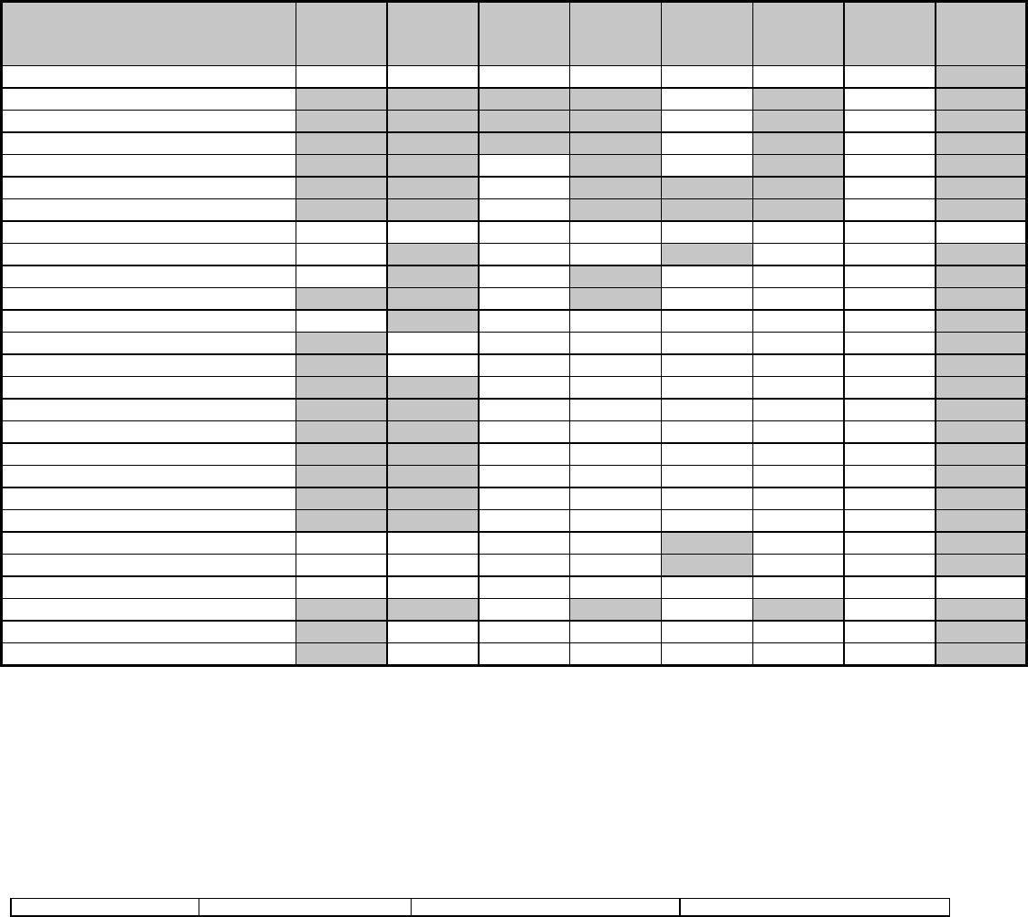
Digital Security Controls Ltd. 51 Private and Confidential
Installation Manual DATE : 09/30/97 DRAFT
[017] FIFTH SYSTEM OPTION CODE
Default Option ON Option OFF
OFF I___I Option 1 WLSKey Does Not Use Access Codes WLSKey Uses Access Codes
ON I___I Option 2 Verbal Chime is Enabled Verbal Chime is Disabled (Beeps only)
ON I___I Option 3 Verbal Alarm is Enabled Verbal Alarm is Disabled (Siren Only)
ON I___I Option 4 Local Annunciation Enabled Local Annunciation Disabledxviii
OFF I___I Option 5 Remote Annunciation Enabled Remote Annunciation Disabled
OFF I___I Option 6 For Future Use
OFF I___I Option 7 For Future Use
OFF I___I Option 8 Squawk on Away Arming/Disarming Only Bell Squawk on all Arming/Disarming
ADVANCED SYSTEM PROGRAMMING
ZONE ATTRIBUTE DEFAULTS
Zone Type
On
Off
Opt. 1
Audible
Silent
Opt. 2
Steady
Pulsed
Opt. 3
Chime
No
Opt. 4
Bypass
No
Opt. 5
Force
No
Opt. 6
Swing.
No
Opt 7
Tx Del.
No
Opt. 8
Wireless
No
00 Null Zone Off Off Off Off Off Off Off On
01 Delay 1 On On On On Off On Off On
02 Delay 2 On On On On Off On Off On
03 Instant On On On On Off On Off On
04 Interior On On Off On Off On Off On
05 Interior, Stay-Away On On Off On On On Off On
06 Delay, Stay-Away On On Off On On On Off On
07-08 Not Usedxix Off Off Off Off Off Off Off Off
09 24 Hour Supervisory Off On Off Off On Off Off On
10 24 Hr Superv. Buzzer Off On Off On Off Off Off On
11 24 Hour Burglary On On Off On Off Off Off On
12 24 Hour Holdup Off On Off Off Off Off Off On
13 24 Hour Gas On Off Off Off Off Off Off On
14 24 Hour Heat On Off Off Off Off Off Off On
15 24 Hour Medical On On Off Off Off Off Off On
16 24 Hour Panic On On Off Off Off Off Off On
17 24 Hour Emergency On On Off Off Off Off Off On
18 24 Hour Sprinkler On On Off Off Off Off Off On
19 24 Hour Water On On Off Off Off Off Off On
20 24 Hour Freeze On On Off Off Off Off Off On
21 24 Hour Latching Tamper On On Off Off Off Off Off On
22 Momentary Keyswitch Off Off Off Off On Off Off On
23 Maintained Keyswitch Off Off Off Off On Off Off On
24 Not Used Off Off Off Off Off Off Off On
25 Interior Delay On On Off On Off On Off On
87 Delayed 24Hr Fire (Wireless) On Off Off Off Off Off Off On
88 Standard 24Hr Fire (Wireless) On Off Off Off Off Off Off On

Digital Security Controls Ltd. 52 Private and Confidential
Installation Manual DATE : 09/30/97 DRAFT
ZONE 1-32 ATTRIBUTES
On
Off
Opt. 1
Audible
Silent
Opt. 2
Steady
Pulsed
Opt. 3
Chime
No
Opt. 4
Bypass
No
Opt. 5
Force
No
Opt. 6
Swing.
No
Opt 7
Tx Del.
No
Opt. 8
Wireless
No
[101] ZONE 1 I____I I____I I____I I____I I____I I____I I____I I____I
[102] ZONE 2 I____I I____I I____I I____I I____I I____I I____I I____I
[103] ZONE 3 I____I I____I I____I I____I I____I I____I I____I I____I
[104] ZONE 4 I____I I____I I____I I____I I____I I____I I____I I____I
[105] ZONE 5 I____I I____I I____I I____I I____I I____I I____I I____I
[106] ZONE 6 I____I I____I I____I I____I I____I I____I I____I I____I
[107] ZONE 7 I____I I____I I____I I____I I____I I____I I____I I____I
[108] ZONE 8 I____I I____I I____I I____I I____I I____I I____I I____I
[109] ZONE 9 I____I I____I I____I I____I I____I I____I I____I I____I
[110] ZONE 10 I____I I____I I____I I____I I____I I____I I____I I____I
[111] ZONE 11 I____I I____I I____I I____I I____I I____I I____I I____I
[112] ZONE 12 I____I I____I I____I I____I I____I I____I I____I I____I
[113] ZONE 13 I____I I____I I____I I____I I____I I____I I____I I____I
[114] ZONE 14 I____I I____I I____I I____I I____I I____I I____I I____I
[115] ZONE 15 I____I I____I I____I I____I I____I I____I I____I I____I
[116] ZONE 16 I____I I____I I____I I____I I____I I____I I____I I____I
[117] ZONE 17 I____I I____I I____I I____I I____I I____I I____I I____I
[118] ZONE 18 I____I I____I I____I I____I I____I I____I I____I I____I
[119] ZONE 19 I____I I____I I____I I____I I____I I____I I____I I____I
[120] ZONE 20 I____I I____I I____I I____I I____I I____I I____I I____I
[121] ZONE 21 I____I I____I I____I I____I I____I I____I I____I I____I
[122] ZONE 22 I____I I____I I____I I____I I____I I____I I____I I____I
[123] ZONE 23 I____I I____I I____I I____I I____I I____I I____I I____I
[124] ZONE 24 I____I I____I I____I I____I I____I I____I I____I I____I
[125] ZONE 25 I____I I____I I____I I____I I____I I____I I____I I____I
[126] ZONE 26 I____I I____I I____I I____I I____I I____I I____I I____I
[127] ZONE 27 I____I I____I I____I I____I I____I I____I I____I I____I
[128] ZONE 28 I____I I____I I____I I____I I____I I____I I____I I____I
[129] ZONE 29 I____I I____I I____I I____I I____I I____I I____I I____I
[130] ZONE 30 I____I I____I I____I I____I I____I I____I I____I I____I
[131] ZONE 31 I____I I____I I____I I____I I____I I____I I____I I____I
[132] ZONE 32 I____I I____I I____I I____I I____I I____I I____I I____I

Digital Security Controls Ltd. 53 Private and Confidential
Installation Manual DATE : 09/30/97 DRAFT
[160] MAXIMUM DIALING ATTEMPTS TO EACH PHONE NUMBER
Default
008 I___II___II___I Valid entries are 001-015 attempts
[161] POST DIAL WAIT FOR HANDSHAKE (ALL FORMATS)
Default
040 I___II___II___I Valid entries are 001-255 seconds
[202] SYSTEM ZONE ASSIGNMENTS
Default Option ON Option OFF
ON I___I Option 1 Zone 1 is Enabled Zone 1 is Disabled
ON I___I Option 2 Zone 2 is Enabled Zone 2 is Disabled
ON I___I Option 3 Zone 3 is Enabled Zone 3 is Disabled
ON I___I Option 4 Zone 4 is Enabled Zone 4 is Disabled
ON I___I Option 5 Zone 5 is Enabled Zone 5 is Disabled
ON I___I Option 6 Zone 6 is Enabled Zone 6 is Disabled
ON I___I Option 7 Zone 7 is Enabled Zone 7 is Disabled
ON I___I Option 8 Zone 8 is Enabled Zone 8 is Disabled
[203] SYSTEM ZONE ASSIGNMENTS 09-16
Default Option ON Option OFF
OFF I___I Option 1 Zone 9 is Enabled Zone 9 is Disabled
OFF I___I Option 2 Zone 10 is Enabled Zone 10 is Disabled
OFF I___I Option 3 Zone 11 is Enabled Zone 11 is Disabled
OFF I___I Option 4 Zone 12 is Enabled Zone 12 is Disabled
OFF I___I Option 5 Zone 13 is Enabled Zone 13 is Disabled
OFF I___I Option 6 Zone 14 is Enabled Zone 14 is Disabled
OFF I___I Option 7 Zone 15 is Enabled Zone 15 is Disabled
OFF I___I Option 8 Zone 16 is Enabled Zone 16 is Disabled
[204] SYSTEM ZONE ASSIGNMENTS 17-24
Default Option ON Option OFF
OFF I___I Option 1 Zone 17 is Enabled Zone 17 is Disabled
OFF I___I Option 2 Zone 18 is Enabled Zone 18 is Disabled
OFF I___I Option 3 Zone 19 is Enabled Zone 19 is Disabled
OFF I___I Option 4 Zone 20 is Enabled Zone 20 is Disabled
OFF I___I Option 5 Zone 21 is Enabled Zone 21 is Disabled
OFF I___I Option 6 Zone 22 is Enabled Zone 22 is Disabled
OFF I___I Option 7 Zone 23 is Enabled Zone 23 is Disabled
OFF I___I Option 8 Zone 24 is Enabled Zone 24 is Disabled
[205] SYSTEM ZONE ASSIGNMENTS 25-32
Default Option ON Option OFF
OFF I___I Option 1 Zone 25 is Enabled Zone 25 is Disabled
OFF I___I Option 2 Zone 26 is Enabled Zone 26 is Disabled
OFF I___I Option 3 Zone 27 is Enabled Zone 27 is Disabled
OFF I___I Option 4 Zone 28 is Enabled Zone 28 is Disabled
OFF I___I Option 5 Zone 29 is Enabled Zone 29 is Disabled
OFF I___I Option 6 Zone 30 is Enabled Zone 30 is Disabled
OFF I___I Option 7 Zone 31 is Enabled Zone 31 is Disabled
OFF I___I Option 8 Zone 32 is Enabled Zone 32 is Disabled

Digital Security Controls Ltd. 54 Private and Confidential
Installation Manual DATE : 09/30/97 DRAFT
COMMUNICATIONS PROGRAMMING
* For Sections [301] to [353], the contents of every section by default is [F].
[301] FIRST TELEPHONE NUMBER (32 Digits)
I__II__II__II__II__II__II__II__II__II__II__II__II__II__II__II__II__II__II__II__II__II__II__II__II__II__II__II__II__II__II__II__I
[302] SECOND TELEPHONE NUMBER (32 Digits)
I__II__II__II__II__II__II__II__II__II__II__II__II__II__II__II__II__II__II__II__II__II__II__II__II__II__II__II__II__II__II__II__I
[303] THIRD TELEPHONE NUMBER (32 Digits)
I__II__II__II__II__II__II__II__II__II__II__II__II__II__II__II__II__II__II__II__II__II__II__II__II__II__II__II__II__II__II__II__I
[310] TELEPHONE NUMBER 1/3 ACCOUNT CODE (4 Digits)
I__II__II__II__I
[311] TELEPHONE NUMBER 2 ACCOUNT CODE (4 Digits)
I__II__II__II__I
[320] ALARM REPORTING CODES, ZONES 1-8
I___II___I Zone 1 Alarm I___II___I Zone 5 Alarm
I___II___I Zone 2 Alarm I___II___I Zone 6 Alarm
I___II___I Zone 3 Alarm I___II___I Zone 7 Alarm
I___II___I Zone 4 Alarm I___II___I Zone 8 Alarm
[321] ALARM REPORTING CODES, ZONES 9-16
I___II___I Zone 9 Alarm I___II___I Zone 13 Alarm
I___II___I Zone 10 Alarm I___II___I Zone 14 Alarm
I___II___I Zone 11 Alarm I___II___I Zone 15 Alarm
I___II___I Zone 12 Alarm I___II___I Zone 16 Alarm
[322] ALARM REPORTING CODES, ZONES 17-24
I___II___I Zone 17 Alarm I___II___I Zone 21 Alarm
I___II___I Zone 18 Alarm I___II___I Zone 22 Alarm
I___II___I Zone 19 Alarm I___II___I Zone 23 Alarm
I___II___I Zone 20 Alarm I___II___I Zone 24 Alarm
[323] ALARM REPORTING CODES, ZONES 25-32
I___II___I Zone 25 Alarm I___II___I Zone 29 Alarm
I___II___I Zone 26 Alarm I___II___I Zone 30 Alarm
I___II___I Zone 27 Alarm I___II___I Zone 31 Alarm
I___II___I Zone 28 Alarm I___II___I Zone 32 Alarm
[324] ALARM RESTORAL REPORTING CODES, ZONES 1-8
I___II___I Zone 1 Alarm Restore I___II___I Zone 5 Alarm Restore
I___II___I Zone 2 Alarm Restore I___II___I Zone 6 Alarm Restore
I___II___I Zone 3 Alarm Restore I___II___I Zone 7 Alarm Restore
I___II___I Zone 4 Alarm Restore I___II___I Zone 8 Alarm Restore
[325] ALARM RESTORAL REPORTING CODES, ZONES 9-16
I___II___I Zone 9 Alarm Restore I___II___I Zone 13 Alarm Restore
I___II___I Zone 10 Alarm Restore I___II___I Zone 14 Alarm Restore
I___II___I Zone 11 Alarm Restore I___II___I Zone 15 Alarm Restore
I___II___I Zone 12 Alarm Restore I___II___I Zone 16 Alarm Restore

Digital Security Controls Ltd. 55 Private and Confidential
Installation Manual DATE : 09/30/97 DRAFT
[326] ALARM RESTORE REPORTING CODES, ZONES 17-24
I___II___I Zone 17 Alarm Restore I___II___I Zone 21 Alarm Restore
I___II___I Zone 18 Alarm Restore I___II___I Zone 22 Alarm Restore
I___II___I Zone 19 Alarm Restore I___II___I Zone 23 Alarm Restore
I___II___I Zone 20 Alarm Restore I___II___I Zone 24 Alarm Restore
[327] ALARM REPORTING CODES, ZONES 25-32
I___II___I Zone 25 Alarm Restore I___II___I Zone 29 Alarm Restore
I___II___I Zone 26 Alarm Restore I___II___I Zone 30 Alarm Restore
I___II___I Zone 27 Alarm Restore I___II___I Zone 31 Alarm Restore
I___II___I Zone 28 Alarm Restore I___II___I Zone 32 Alarm Restore
[328] MISCELLANEOUS ALARM REPORTING CODES
I___II___I Duress Alarm I___II___I Not Used
I___II___I Opening After Alarm I___II___I Not Used
I___II___I Recent Closing I___II___I Cross Zone Police Code Alarm
[329] PRIORITY ALARM AND RESTORAL REPORTING CODES
I___II___I Keypad [F]ire Alarm I___II___I Keypad [F]ire Restoral
I___II___I Keypad [A]uxiliary Alarm I___II___I Keypad [A]uxiliary Restoral
I___II___I Keypad [P]anic Alarm I___II___I Keypad [P]anic Restoral
I___II___I Not Used I___II___I Not Used
[330] TAMPER REPORTING CODES, ZONES 1-8
I___II___I Zone 1 Tamper I___II___I Zone 5 Tamper
I___II___I Zone 2 Tamper I___II___I Zone 6 Tamper
I___II___I Zone 3 Tamper I___II___I Zone 7 Tamper
I___II___I Zone 4 Tamper I___II___I Zone 8 Tamper
[331] TAMPER REPORTING CODES, ZONES 9-16
I___II___I Zone 9 Tamper I___II___I Zone 13 Tamper
I___II___I Zone 10 Tamper I___II___I Zone 14 Tamper
I___II___I Zone 11 Tamper I___II___I Zone 15 Tamper
I___II___I Zone 12 Tamper I___II___I Zone 16 Tamper
[332] TAMPER REPORTING CODES, ZONES 17-24
I___II___I Zone 17 Tamper I___II___I Zone 21 Tamper
I___II___I Zone 18 Tamper I___II___I Zone 22 Tamper
I___II___I Zone 19 Tamper I___II___I Zone 23 Tamper
I___II___I Zone 20 Tamper I___II___I Zone 24 Tamper
[333] TAMPER REPORTING CODES, ZONES 17-24
I___II___I Zone 25 Tamper I___II___I Zone 29 Tamper
I___II___I Zone 26 Tamper I___II___I Zone 30 Tamper
I___II___I Zone 27 Tamper I___II___I Zone 31 Tamper
I___II___I Zone 28 Tamper I___II___I Zone 32 Tamper
[334] TAMPER RESTORAL REPORTING CODES, ZONES 1-8
I___II___I Zone 1 Tamper Restoral I___II___I Zone 5 Tamper Restoral
I___II___I Zone 2 Tamper Restoral I___II___I Zone 6 Tamper Restoral
I___II___I Zone 3 Tamper Restoral I___II___I Zone 7 Tamper Restoral
I___II___I Zone 4 Tamper Restoral I___II___I Zone 8 Tamper Restoral

Digital Security Controls Ltd. 56 Private and Confidential
Installation Manual DATE : 09/30/97 DRAFT
[335] TAMPER RESTORAL REPORTING CODES, ZONES 9-16
I___II___I Zone 9 Tamper Restoral I___II___I Zone 13 Tamper Restoral
I___II___I Zone 10 Tamper Restoral I___II___I Zone 14 Tamper Restoral
I___II___I Zone 11 Tamper Restoral I___II___I Zone 15 Tamper Restoral
I___II___I Zone 12 Tamper Restoral I___II___I Zone 16 Tamper Restoral
[336] TAMPER RESTORAL REPORTING CODES, ZONES 17-24
I___II___I Zone 17 Tamper Restoral I___II___I Zone 21 Tamper Restoral
I___II___I Zone 18 Tamper Restoral I___II___I Zone 22 Tamper Restoral
I___II___I Zone 19 Tamper Restoral I___II___I Zone 23 Tamper Restoral
I___II___I Zone 20 Tamper Restoral I___II___I Zone 24 Tamper Restoral
[337] TAMPER RESTORAL REPORTING CODES, ZONES 17-24
I___II___I Zone 25 Tamper Restoral I___II___I Zone 29 Tamper Restoral
I___II___I Zone 26 Tamper Restoral I___II___I Zone 30 Tamper Restoral
I___II___I Zone 27 Tamper Restoral I___II___I Zone 31 Tamper Restoral
I___II___I Zone 28 Tamper Restoral I___II___I Zone 32 Tamper Restoral
[338] MISCELLANEOUS TAMPER REPORTING CODES
I___II___I Keypad Lockoutxx
[339] CLOSING (ARMING) REPORTING CODES, ACCESS CODES 1-8
I___II___I Closing by Access Code 1 I___II___I Closing by Access Code 5
I___II___I Closing by Access Code 2 I___II___I Closing by Access Code 6
I___II___I Closing by Access Code 3 I___II___I Closing by Access Code 7
I___II___I Closing by Access Code 4 I___II___I Closing by Access Code 8
[340] CLOSING (ARMING) REPORTING CODES, ACCESS CODES 9-16
I___II___I Closing by Access Code 9 I___II___I Closing by Access Code 13
I___II___I Closing by Access Code 10 I___II___I Closing by Access Code 14
I___II___I Closing by Access Code 11 I___II___I Closing by Access Code 15
I___II___I Closing by Access Code 12 I___II___I Closing by Access Code 16
[341] CLOSING (ARMING) REPORTING CODES, ACCESS CODES 17-24
I___II___I Closing by Access Code 17 I___II___I Closing by Access Code 21
I___II___I Closing by Access Code 18 I___II___I Closing by Access Code 22
I___II___I Closing by Access Code 19 I___II___I Closing by Access Code 23
I___II___I Closing by Access Code 20 I___II___I Closing by Access Code 24
[342] CLOSING (ARMING) REPORTING CODES, ACCESS CODES 25-32
I___II___I Closing by Access Code 25 I___II___I Closing by Access Code 29
I___II___I Closing by Access Code 26 I___II___I Closing by Access Code 30
I___II___I Closing by Access Code 27 I___II___I Closing by Access Code 31
I___II___I Closing by Access Code 28 I___II___I Closing by Access Code 32
[343] MISCELLANEOUS CLOSING (ARMING) REPORTING CODES
I___II___I Closing by Duress Code 33 I___II___I Closing by System Code 42
I___II___I Closing by Duress Code 34 I___II___I Partial Closing
I___II___I Closing by System Code 40 I___II___I Special Closing
I___II___I Closing by System Code 41

Digital Security Controls Ltd. 57 Private and Confidential
Installation Manual DATE : 09/30/97 DRAFT
[344] OPENING (DISARMING) REPORTING CODES, ACCESS CODES 1-8
I___II___I Opening by Access Code 1 I___II___I Opening by Access Code 5
I___II___I Opening by Access Code 2 I___II___I Opening by Access Code 6
I___II___I Opening by Access Code 3 I___II___I Opening by Access Code 7
I___II___I Opening by Access Code 4 I___II___I Opening by Access Code 8
[345] OPENING (DISARMING) REPORTING CODES, ACCESS CODES 9-16
I___II___I Opening by Access Code 9 I___II___I Opening by Access Code 13
I___II___I Opening by Access Code 10 I___II___I Opening by Access Code 14
I___II___I Opening by Access Code 11 I___II___I Opening by Access Code 15
I___II___I Opening by Access Code 12 I___II___I Opening by Access Code 16
[346] OPENING (DISARMING) REPORTING CODES, ACCESS CODES 17-24
I___II___I Opening by Access Code 17 I___II___I Opening by Access Code 21
I___II___I Opening by Access Code 18 I___II___I Opening by Access Code 22
I___II___I Opening by Access Code 19 I___II___I Opening by Access Code 23
I___II___I Opening by Access Code 20 I___II___I Opening by Access Code 24
[347] OPENING (DISARMING) REPORTING CODES, ACCESS CODES 25-32
I___II___I Opening by Access Code 25 I___II___I Opening by Access Code 29
I___II___I Opening by Access Code 26 I___II___I Opening by Access Code 30
I___II___I Opening by Access Code 27 I___II___I Opening by Access Code 31
I___II___I Opening by Access Code 28 I___II___I Opening by Access Code 32
[348] MISCELLANEOUS OPENING (DISARMING) REPORTING CODES
I___II___I Opening by Duress Code 33 I___II___I Opening by System Code 42
I___II___I Opening by Duress Code 34 I___II___I Auto-arm Cancellation
I___II___I Opening by System Code 40 I___II___I Special Opening
I___II___I Opening by System Code 41
[349] MAINTENANCE ALARM REPORTING CODES
I___II___I Battery Trouble Alarm I___II___I Not Used
I___II___I AC Failure Trouble Alarm I___II___I Not Used
I___II___I Remote Sounder Trouble Alarm I___II___I General System Trouble
I___II___I Fire Trouble Alarm I___II___I Not Used
[350] MAINTENANCE RESTORAL REPORTING CODES
I___II___I Battery Trouble Restoral I___II___I Not Used
I___II___I AC Failure Trouble Restoral I___II___I TLM Restoral
I___II___I Remote Sounder Restoral I___II___I General System Trouble Restore
I___II___I Fire Trouble Restoral I___II___I Not Used
[351] MISCELLANEOUS MAINTENANCE REPORTING CODES
I___II___I Phone #1 FTC Restore I___II___I DLS Lead OUT
I___II___I Phone #2 FTC Restore I___II___I Zone Fault Alarm
I___II___I Event Buffer 75% Full I___II___I Zone Fault Restore
I___II___I DLS Lead IN I___II___I Delinquency Reporting Code
[352] TEST TRANSMISSION REPORTING CODES
I___II___I Periodic Test Transmission I___II___I Not Used
I___II___I System Test
[353] WIRELESS MAINTENANCE REPORTING CODES
I___II___I General Zone Low Battery Alarm I___II___I General Zone Low Battery Restore
[360] COMMUNICATOR FORMAT OPTIONS

Digital Security Controls Ltd. 58 Private and Confidential
Installation Manual DATE : 09/30/97 DRAFT
01 20 BPS, 1400 Hz handshake Note: 3rd Phone Number follows the
02 20 BPS, 2300 Hz handshake format of the 1st Phone Number
03 DTMF CONTACT I.D.
04 SIA FSK
05 Pager
Default
04 I___II___I 1st Phone Number
04 I___II___I 2nd Phone Number
[361] ALARM / RESTORE COMMUNICATOR CALL DIRECTIONS
Default Option ON Option OFF
ON I___I Option 1 1st Telephone Number Disabled
OFF I___I Option 2 2nd Telephone Number Disabled
OFF I___I Option 3-8 For Future Use
[363] TAMPER ALARM / RESTORE COMMUNICATOR CALL DIRECTIONS
Default Option ON Option OFF
ON I___I Option 1 1st Telephone Number Disabled
OFF I___I Option 2 2nd Telephone Number Disabled
OFF I___I Option 3-8 For Future Use
[365] OPENING / CLOSING COMMUNICATOR CALL DIRECTIONS
Default Option ON Option OFF
ON I___I Option 1 1st Telephone Number Disabled
OFF I___I Option 2 2nd Telephone Number Disabled
OFF I___I Option 3-8 For Future Use
[367] SYSTEM MAINTENANCE ALARM / RESTORE COMMUNICATOR CALL DIRECTIONS
Default Option ON Option OFF
ON I___I Option 1 1st Telephone Number Disabled
OFF I___I Option 2 2nd Telephone Number Disabled
OFF I___I Option 3-8 For Future Use
[368] SYSTEM TEST TRANSMISSIONS COMMUNICATOR CALL DIRECTIONS
Default Option ON Option OFF
ON I___I Option 1 1st Telephone Number Disabled
OFF I___I Option 2 2nd Telephone Number Disabled
OFF I___I Option 3-8 For Future Use
[370] COMMUNICATION VARIABLES
Default
003 I___II___II___I Swinger Shutdown (Alarms & Rest) (000-255 Transmissions, 000=disabled)
003 I___II___II___I Swinger Shutdown (Tampers & Rest) (000-255 Transmissions, 000=disabled)
003 I___II___II___I Swinger Shutdown (Maint & Rest) (000-255 Transmissions, 000=disabled)
000 I___II___II___I Communication Delay (000-255 seconds)
030 I___II___II___I AC Failure Communication Delay (000-255 minutes)
003 I___II___II___I TLM Trouble Delay (# of valid checks required +3= 003-255x10s)
030 I___II___II___I Test Transmission Cycle (land-line) (000-255 days)/(000-255 mins)
007 I___II___II___I Zone Low Battery Transmission Delay (000-255 days)
030 I___II___II___I Delinquency Transmission Delay (000-255 days/hours)
[371] TEST TRANSMISSION TIME OF DAY

Digital Security Controls Ltd. 59 Private and Confidential
Installation Manual DATE : 09/30/97 DRAFT
Default
9999 I___II___II___II___I (Valid entries are 0000-2359, 9999 to disable)
[380] FIRST COMMUNICATOR OPTION CODE
Default Option ON Option OFF
ON I___I Option 1 Communications Enabled Communications Disabled
OFF I___I Option 2 Restorals on Bell Time-out Restorals Follow Zones
OFF I___I Option 3 Pulse Dialing DTMF Dialing
ON I___I Option 4 Switch to Pulse Dialing on 5th Attempt DTMF Dial For All 8 Attempts
OFF I___I Option 5 3rd Phone Number Enabled 3rd Phone Number Disabled
OFF I___I Option 6 Alternate Dial (1st & 3rd) Call 1st Number, Backup to 3rd
OFF I___I Option 7 Not Used
OFF I___I Option 8 Delinquency Follows Zone Activity (Hours) Delinquency Follows Arming (Days)
[381] SECOND COMMUNICATOR OPTION CODE
Default Option ON Option OFF
OFF I___I Option 1 Opening After Alarm Kypd Ringback Enabled Opn After Alrm Kypd Ringback Disabled
OFF I___I Option 2 Opening After Alarm Bell Ringback Enabled Opn After Alrm Bell Ringback Disabled
OFF I___I Option 3 SIA Uses Programmed Rep. Codes SIA Uses Automatic Rep. Codes
OFF I___I Option 4 Closing Confirmation Enabled Closing Confirmation Disabled
ON I___I Option 5 Talk/Listen on Phone #1/3 Enabled Talk/Listen on Phone #1/3 Disabled
OFF I___I Option 6 Talk/Listen on Phone #2 Enabled Talk/Listen on Phone #2 Disabled
ON I___I Option 7 Contact I.D. Uses Pgm’d Rep. Codes Contact I.D. Uses Auto Rep. Codes
OFF I___I Option 8 For Future Use
DOWNLOADING PROGRAMMING
[401] FIRST DOWNLOADING OPTION CODE
Default Option ON Option OFF
OFF I___I Option 1 Answering Machine / Double Call Enabled Answ. Machine / Double Call Disabled
ON I___I Option 2 User Can Enable DLS Window User Can Not Enable DLS Window
OFF I___I Option 3 Call-Back Enabled Call-Back Disabled
OFF I___I Option 4 User Initiated Call-up Enabled User Initiated Call-up Disabled
OFF I___I Option 5 Auto Event Buffer Upload Enabled Auto Event Buffer Upload Disabled
OFF I___I Option 6 For Future Use
OFF I___I Option 7 For Future Use
OFF I___I Option 8 For Future Use
[402] DOWNLOADING COMPUTER'S TELEPHONE NUMBER (32 Digits)
I__II__II__II__II__II__II__II__II__II__II__II__II__II__II__II__II__II__II__II__II__II__II__II__II__II__II__II__II__II__II__II__I
[403] DOWNLOADING ACCESS CODE
Default
9000 I__II__II__II__I Enter 4 Hexadecimal Digits.
[404] PANEL IDENTIFICATION CODE
Default
9000 I__II__II__II__I Enter 4 Hexadecimal Digits.

Digital Security Controls Ltd. 60 Private and Confidential
Installation Manual DATE : 09/30/97 DRAFT
[405] ANSWERING MACHINE DOUBLE-CALL TIMER
Default
060 I__II__II__I (Valid entries are 001-255 seconds)
[406] NUMBER OF RINGS TO ANSWER ON
Default
000 I__II__II__I (Valid entries are 000-255 rings)
[499][Installer Code][499] INITIATE PCLINK
• ENTER [499] [INSTALLER CODE] [499]
INTERNATIONAL PROGRAMMING
[700] AUTOMATIC CLOCK ADJUST
Default
60 I___II___I (Valid entries are 00-99)
[701] FIRST INTERNATIONAL OPTIONS CODE
Default Option ON Option OFF
OFF I___I Option 1 50 Hz AC 60 Hz AC
OFF I___I Option 2 Time Base is Internal Crystal Time Base is AC Line
OFF I___I Option 3 AC/DC Arming Inhibit Enabled AC/DC Arming Inhibit Disabled
OFF I___I Option 4 All System Tampers Require Installer Reset All System Tampers follow Restore
OFF I___I Option 5 6-Digit User Access Codes 4-Digit User Access Codes
OFF I___I Option 6 Busy Tone Detection Enabled Busy Tone Detection Disabled
OFF I___I Option 7 High Current Battery Charge Standard Current Battery Charge
OFF I___I Option 8 For Future Use
[702] SECOND INTERNATIONAL OPTIONS CODE
Default Option ON Option OFF
OFF I___I Option 1 Pulse Dialing Make/Break Ratio is 33/67 Pulse Dialing Make/Break Ratio is 40/60
ON I___I Option 2 Force Dialing Enabled Force Dialing Disabled
OFF I___I Option 3 Land Line Test Tx Interval is in Minutes Land Line Test Tx Interval is in Days
OFF I___I Option 4 1600 Hz Handshake Standard Handshake
OFF I___I Option 5 ID Tone Enabled ID Tone Disabled
OFF I___I Option 6 2100 HZ ID Tone 1300 Hz ID Tone
OFF I___I Option 7 One Time 1-Hr User Enabled DLS Window Full 6-Hr User Enabled DLS Window
OFF I___I Option 8 Bell on FTC when armed FTC Trouble only when armed
[703] DELAY BETWEEN DIALING ATTEMPTS
Default
001 I___II___II___I (Valid entries are 000-255 seconds)
[801] NOT USED
[802] AUDIO INTERFACE
[10] Port Assignments, Zones 1-8
• Enter the nearest Intercom Port Number (01= Main Unit, 02= Remote Sounder, 00 = Not Used)

Digital Security Controls Ltd. 61 Private and Confidential
Installation Manual DATE : 09/30/97 DRAFT
Default
00 I___II___I Zone 1 Port Assignment
00 I___II___I Zone 2 Port Assignment
00 I___II___I Zone 3 Port Assignment
00 I___II___I Zone 4 Port Assignment
00 I___II___I Zone 5 Port Assignment
00 I___II___I Zone 6 Port Assignment
00 I___II___I Zone 7 Port Assignment
00 I___II___I Zone 8 Port Assignment
[11] Port Assignments, Zones 9-16
• Enter the nearest Intercom Port Number (01= Main Unit, 02= Remote Sounder, 00 = Not Used)
Default
00 I___II___I Zone 9 Port Assignment
00 I___II___I Zone 10 Port Assignment
00 I___II___I Zone 11 Port Assignment
00 I___II___I Zone 12 Port Assignment
00 I___II___I Zone 13 Port Assignment
00 I___II___I Zone 14 Port Assignment
00 I___II___I Zone 15 Port Assignment
00 I___II___I Zone 16 Port Assignment
[12] Port Assignments, Zones 17-24
• Enter the nearest Intercom Port Number (01= Main Unit, 02= Remote Sounder, 00 = Not Used)
Default
00 I___II___I Zone 17 Port Assignment
00 I___II___I Zone 18 Port Assignment
00 I___II___I Zone 19 Port Assignment
00 I___II___I Zone 20 Port Assignment
00 I___II___I Zone 21 Port Assignment
00 I___II___I Zone 22 Port Assignment
00 I___II___I Zone 23 Port Assignment
00 I___II___I Zone 24 Port Assignment
[13] Port Assignments, Zones 25-32
• Enter the nearest Intercom Port Number (01= Main Unit, 02= Remote Sounder, 00 = Not Used)
Default
00 I___II___I Zone 25 Port Assignment
00 I___II___I Zone 26 Port Assignment
00 I___II___I Zone 27 Port Assignment
00 I___II___I Zone 28 Port Assignment
00 I___II___I Zone 29 Port Assignment
00 I___II___I Zone 30 Port Assignment
00 I___II___I Zone 31 Port Assignment
00 I___II___I Zone 32 Port Assignment
[20] General Broadcast Mask
Default Option ON Option OFF
Off I___I Option 1 For Future Use
On I___I Option 2 Incoming Sounds on Main Unit Enabled Incoming Sounds on Main Unit Disabled
Off I___I Option 3 Incoming Sounds on Rem. Sndr Enab. Incoming Sounds on Rem Sndr. Disabled
Off I___I Option 4-8 Not Used
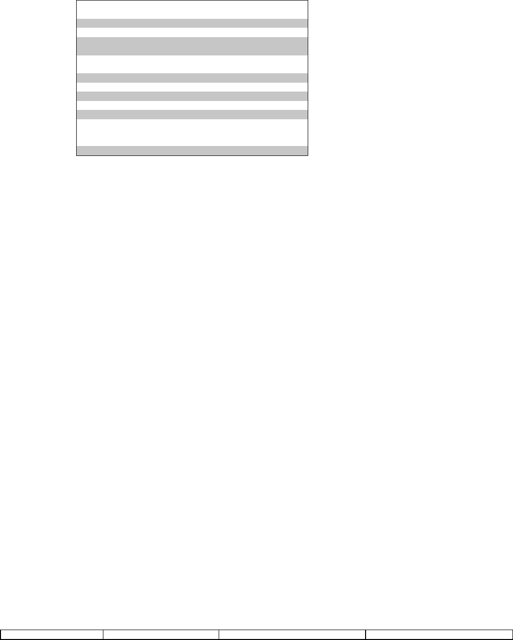
Digital Security Controls Ltd. 62 Private and Confidential
Installation Manual DATE : 09/30/97 DRAFT
AUDIO CONTROL TELEPHONE KEY FUNCTIONS
[00] Unused Key
[01] Talk To All Speakers
[02] Not Used
[03] High Gain Listen To All
[04] Not Used
[05] Not Used
[06] Low Gain Listen To All
[07] Extend Time
[08] For Future Use
[09] Terminate Session
[10] For Future Use
[11] Cancel First Keypress
[12] For Future Use
[13] Zone Select (0 3 only)
[14] Increment Selected Microphone (Input)
[15] Decrement Selected Microphone (Input)
[16]-[17] Not Used
[40] Audio Control Telephone Key Programming
Default
01 I___II___I [1] Key
00 I___II___I [2] Key
03 I___II___I [3] Key
14 I___II___I [4] Key
15 I___II___I [5] Key
06 I___II___I [6] Key
07 I___II___I [7] Key
00 I___II___I [8] Key
17 I___II___I [9] Key
00 I___II___I [0] Key
17 I___II___I [*] Key
11 I___II___I [#] Key
[54] Fifth Audio Control Option Code
Default Option ON Option OFF
OFF I___I Option 1 Tampers Enabled Disabled
OFF I___I Option 2 Openings & Closings Enabled Disabled
OFF I___I Option 3 [A] Key Alarm Enabled Disabled
OFF I___I Option 4 [P] Key Alarm Enabled (Listen) Disabled
OFF I___I Option 5 Duress Alarm Enabled (Listen) Disabled
OFF I___I Option 6 Not Used
OFF I___I Option 7 Opening After Alarm Enabled Disabled
OFF I___I Option 8 For Future Use
NOTE: If any event is enabled for Talk/Listen In, Communications MUST be enabled.
[55] Audio Duration
Default
90 I___II___I (Valid entries are 01-99 Seconds)
[60] Telephone Ring Mask
Default Option ON Option OFF

Digital Security Controls Ltd. 63 Private and Confidential
Installation Manual DATE : 09/30/97 DRAFT
Off I___I Option 1 For Future Use
Off I___I Option 2 Main Unit Telephone Ring Enabled Main Unit Telephone Ring Disabled
Off I___I Option 3 Remote Sounder Telephone Ring Enab. Remote Sounder Telephone Ring Disabled
Off I___I Option 4-8 Not Used
[803] NOT USED
[804] WIRELESS RECEIVER PROGRAMMING
[01] Zone 1 Serial Number 000000 I___II___II___II___II___II___I
• 6 digit Hexadecimal entry is required
• 1st digit represents Transmitter Type:
2 = UTX 5 = Panic Pendant
3 = Sensors (PIR, Glassbreak) 6/9 = WLSKey
4 = Smoke 7 = Handheld Keypad
• 0 must be entered in front of transmitters that have only 5 digit serial numbers
[02] Zone 2 Serial Number 000000 I___II___II___II___II___II___I
[03] Zone 3 Serial Number 000000 I___II___II___II___II___II___I
[04] Zone 4 Serial Number 000000 I___II___II___II___II___II___I
[05] Zone 5 Serial Number 000000 I___II___II___II___II___II___I
[06] Zone 6 Serial Number 000000 I___II___II___II___II___II___I
[07] Zone 7 Serial Number 000000 I___II___II___II___II___II___I
[08] Zone 8 Serial Number 000000 I___II___II___II___II___II___I
[09] Zone 9 Serial Number 000000 I___II___II___II___II___II___I
[10] Zone 10 Serial Number 000000 I___II___II___II___II___II___I
[11] Zone 11 Serial Number 000000 I___II___II___II___II___II___I
[12] Zone 12 Serial Number 000000 I___II___II___II___II___II___I
[13] Zone 13 Serial Number 000000 I___II___II___II___II___II___I
[14] Zone 14 Serial Number 000000 I___II___II___II___II___II___I
[15] Zone 15 Serial Number 000000 I___II___II___II___II___II___I
[16] Zone 16 Serial Number 000000 I___II___II___II___II___II___I
[17] Zone 17 Serial Number 000000 I___II___II___II___II___II___I
[18] Zone 18 Serial Number 000000 I___II___II___II___II___II___I
[19] Zone 19 Serial Number 000000 I___II___II___II___II___II___I
[20] Zone 20 Serial Number 000000 I___II___II___II___II___II___I
[21] Zone 21 Serial Number 000000 I___II___II___II___II___II___I
[22] Zone 22 Serial Number 000000 I___II___II___II___II___II___I
[23] Zone 23 Serial Number 000000 I___II___II___II___II___II___I
[24] Zone 24 Serial Number 000000 I___II___II___II___II___II___I
[25] Zone 25 Serial Number 000000 I___II___II___II___II___II___I
[26] Zone 26 Serial Number 000000 I___II___II___II___II___II___I
[27] Zone 27 Serial Number 000000 I___II___II___II___II___II___I
[28] Zone 28 Serial Number 000000 I___II___II___II___II___II___I
[29] Zone 29 Serial Number 000000 I___II___II___II___II___II___I
[30] Zone 30 Serial Number 000000 I___II___II___II___II___II___I
[31] Zone 31 Serial Number 000000 I___II___II___II___II___II___I
[32] Zone 32 Serial Number 000000 I___II___II___II___II___II___I
HANDHELD KEYPAD SERIAL NUMBERS
[33] Keypad #1 Serial Number 000000 I___II___II___II___II___II___I
[34] Keypad #2 Serial Number 000000 I___II___II___II___II___II___I

Digital Security Controls Ltd. 64 Private and Confidential
Installation Manual DATE : 09/30/97 DRAFT
[35] Keypad #3 Serial Number 000000 I___II___II___II___II___II___I
[36] Keypad #4 Serial Number 000000 I___II___II___II___II___II___I
WIRELESS KEY SERIAL NUMBERS
[41] Wireless Key #01 Serial Number 000000 I___II___II___II___II___II___I
[42] Wireless Key #02 Serial Number 000000 I___II___II___II___II___II___I
[43] Wireless Key #03 Serial Number 000000 I___II___II___II___II___II___I
[44] Wireless Key #04 Serial Number 000000 I___II___II___II___II___II___I
[45] Wireless Key #05 Serial Number 000000 I___II___II___II___II___II___I
[46] Wireless Key #06 Serial Number 000000 I___II___II___II___II___II___I
[47] Wireless Key #07 Serial Number 000000 I___II___II___II___II___II___I
[48] Wireless Key #08 Serial Number 000000 I___II___II___II___II___II___I
[49] Wireless Key #09 Serial Number 000000 I___II___II___II___II___II___I
[50] Wireless Key #10 Serial Number 000000 I___II___II___II___II___II___I
[51] Wireless Key #11 Serial Number 000000 I___II___II___II___II___II___I
[52] Wireless Key #12 Serial Number 000000 I___II___II___II___II___II___I
[53] Wireless Key #13 Serial Number 000000 I___II___II___II___II___II___I
[54] Wireless Key #14 Serial Number 000000 I___II___II___II___II___II___I
[55] Wireless Key #15 Serial Number 000000 I___II___II___II___II___II___I
[56] Wireless Key #16 Serial Number 000000 I___II___II___II___II___II___I
Note: Serial Numbers are also Programmed via the Wizard.
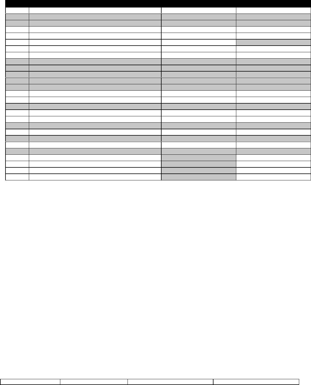
Digital Security Controls Ltd. 65 Private and Confidential
Installation Manual DATE : 09/30/97 DRAFT
HANDHELD KEYPAD / WIRELESS KEY FUNCTION KEY OPTIONS
Entry Description Handheld Keypad Wireless Key
00 Null Key (Key Not Used) YES YES
01 Partition 1 Select (Not Used) NO NO
02 Partition 2 Select (Not Used) NO NO
03 Stay Arm YES YES
04 Away Arm YES YES
05 [*][9] No-Entry Arm YES NO
06 [*][4] Chime On / Off YES YES
07 [*][6][----][4] System Test YES YES
08 [*][1] Bypass Mode (Not Used) NO NO
09 [*][2] Trouble Display (Not Used) NO NO
10 [*][3] Alarm Memory (Not Used) NO NO
11 [*][5] User Programming (Not Used) NO NO
12 [*][6] User Functions (Not Used) NO NO
13 Command Output 1 [*][7][1] YES YES
14 Command Output 2 [*][7][2] YES YES
15 General Voice Prompted Help (Not Used) NO NO
16 [*][0] Quick Exit YES YES
17 [*][1] Activate Stay Aways YES YES
18 Identified Voice Prompted Help (Not Used) NO NO
19 Command Output 3 [*][7][3] YES YES
20 Pendant Test (Not Used) NO NO
21 Command Output 4 [*][7][4] YES YES
22-26 For Future Use/Not Used NO NO
27 Disarm (Off) NO YES
28 Fire Alarm NO YES
29 Auxiliary Alarm NO YES
30 Panic Alarm NO YES
Note: If using Unidentified Wireless Keys for arming, Quick Arming must be enabled.
If using Unidentified Wireless Keys for activating PGM Outputs, the option for requiring access code for activation MUST be OFF.
Defaultxxi
[57] Keypad Function Key 1 03 I___I I___I
[58] Keypad Function Key 2 04 I___I I___I
[59] Keypad Function Key 3 16 I___I I___I
[60] Keypad Function Key 4 31 I___I I___I
[61] Wireless Key Function Key 1 03 I___I I___I
[62] Wireless Key Function Key 2 04 I___I I___I
[63] Wireless Key Function Key 3 27 I___I I___I
[64] Wireless Key Function Key 4 31 I___I I___I

Digital Security Controls Ltd. 66 Private and Confidential
Installation Manual DATE : 09/30/97 DRAFT
Defaultxxii
[71] Hardwired Zone Loop #1 Assignment 00 I___II___I (Valid entries are Zones 01-32)
[72] Hardwired Zone Loop #2 Assignment 00 I___II___I
Note: Hardwired Zones override any Wireless Zones that may be programmed for the same zone number.
Fire Zones are not supported on these Zone Loops.
SUPERVISION
[81] WIRELESS SUPERVISORY WINDOW
Default
03 I___II___I RF Transmitter Supervisory Window (hours), Valid entries are 01-24
MANUAL NOTE: Panic Transmitters are NOT supervised and must be disabled in these sections.
[82] ZONE TRANSMITTER SUPERVISION OPTIONS (1-8)
Default Option ON Option OFF
ON I___I Option 1 Zone 01 Supervision Enabled Zone 01 Superv. Disabled
ON I___I Option 2 Zone 02 Supervision Enabled Zone 02 Superv. Disabled
ON I___I Option 3 Zone 03 Supervision Enabled Zone 03 Superv. Disabled
ON I___I Option 4 Zone 04 Supervision Enabled Zone 04 Superv. Disabled
ON I___I Option 5 Zone 05 Supervision Enabled Zone 05 Superv. Disabled
ON I___I Option 6 Zone 06 Supervision Enabled Zone 06 Superv. Disabled
ON I___I Option 7 Zone 07 Supervision Enabled Zone 07 Superv. Disabled
ON I___I Option 8 Zone 08 Supervision Enabled Zone 08 Superv. Disabled
[83] ZONE TRANSMITTER SUPERVISION OPTIONS (9-16)
Default Option ON Option OFF
ON I___I Option 1 Zone 09 Supervision Enabled Zone 09 Superv. Disabled
ON I___I Option 2 Zone 10 Supervision Enabled Zone 10 Superv. Disabled
ON I___I Option 3 Zone 11 Supervision Enabled Zone 11 Superv. Disabled
ON I___I Option 4 Zone 12 Supervision Enabled Zone 12 Superv. Disabled
ON I___I Option 5 Zone 13 Supervision Enabled Zone 13 Superv. Disabled
ON I___I Option 6 Zone 14 Supervision Enabled Zone 14 Superv. Disabled
ON I___I Option 7 Zone 15 Supervision Enabled Zone 15 Superv. Disabled
ON I___I Option 8 Zone 16 Supervision Enabled Zone 16 Superv. Disabled
[84] ZONE TRANSMITTER SUPERVISION OPTIONS (17-24)
Default Option ON Option OFF
ON I___I Option 1 Zone 17 Supervision Enabled Zone 17 Superv. Disabled
ON I___I Option 2 Zone 18 Supervision Enabled Zone 18 Superv. Disabled
ON I___I Option 3 Zone 19 Supervision Enabled Zone 19 Superv. Disabled
ON I___I Option 4 Zone 20 Supervision Enabled Zone 20 Superv. Disabled
ON I___I Option 5 Zone 21 Supervision Enabled Zone 21 Superv. Disabled
ON I___I Option 6 Zone 22 Supervision Enabled Zone 22 Superv. Disabled
ON I___I Option 7 Zone 23 Supervision Enabled Zone 23 Superv. Disabled
ON I___I Option 8 Zone 24 Supervision Enabled Zone 24 Superv. Disabled
[85] ZONE TRANSMITTER SUPERVISION OPTIONS (25-32)
Default Option ON Option OFF
ON I___I Option 1 Zone 25 Supervision Enabled Zone 25 Superv. Disabled
ON I___I Option 2 Zone 26 Supervision Enabled Zone 26 Superv. Disabled

Digital Security Controls Ltd. 67 Private and Confidential
Installation Manual DATE : 09/30/97 DRAFT
ON I___I Option 3 Zone 27 Supervision Enabled Zone 27 Superv. Disabled
ON I___I Option 4 Zone 28 Supervision Enabled Zone 28 Superv. Disabled
ON I___I Option 5 Zone 29 Supervision Enabled Zone 29 Superv. Disabled
ON I___I Option 6 Zone 30 Supervision Enabled Zone 30 Superv. Disabled
ON I___I Option 7 Zone 31 Supervision Enabled Zone 31 Superv. Disabled
ON I___I Option 8 Zone 32 Supervision Enabled Zone 32 Superv. Disabled
[90] WIRELESS KEYPAD (1-4) ENABLE/DISABLE
Default Option ON Option OFF
OFF I___I Option 1 Keypad #1 is Disabled Keypad #1 is Enabled
OFF I___I Option 2 Keypad #2 is Disabled Keypad #2 is Enabled
OFF I___I Option 3 Keypad #3 is Disabled Keypad #3 is Enabled
OFF I___I Option 4 Keypad #4 is Disabled Keypad #4 is Enabled
[91] WIRELESS KEYS (1-8) ENABLE/DISABLE
Default Option ON Option OFF
OFF I___I Option 1 Wireless Key #01 is Disabled Key #01 is Enabled
OFF I___I Option 2 Wireless Key #02 is Disabled Key #02 is Enabled
OFF I___I Option 3 Wireless Key #03 is Disabled Key #03 is Enabled
OFF I___I Option 4 Wireless Key #04 is Disabled Key #04 is Enabled
OFF I___I Option 5 Wireless Key #05 is Disabled Key #05 is Enabled
OFF I___I Option 6 Wireless Key #06 is Disabled Key #06 is Enabled
OFF I___I Option 7 Wireless Key #07 is Disabled Key #07 is Enabled
OFF I___I Option 8 Wireless Key #08 is Disabled Key #08 is Enabled
[92] WIRELESS KEYS (9-16) ENABLE/DISABLE
Default Option ON Option OFF
OFF I___I Option 1 Wireless Key #09 is Disabled Key #09 is Enabled
OFF I___I Option 2 Wireless Key #10 is Disabled Key #10 is Enabled
OFF I___I Option 3 Wireless Key #11 is Disabled Key #11 is Enabled
OFF I___I Option 4 Wireless Key #12 is Disabled Key #12 is Enabled
OFF I___I Option 5 Wireless Key #13 is Disabled Key #13 is Enabled
OFF I___I Option 6 Wireless Key #14 is Disabled Key #14 is Enabled
OFF I___I Option 7 Wireless Key #15 is Disabled Key #15 is Enabled
OFF I___I Option 8 Wireless Key #16 is Disabled Key #16 is Enabled
[93] RF JAM DETECT ZONE
Default
00 I___II___I Select an unused zone that will go open when a jamming signal is present.
(Valid entry = 01 – 32, 00 = Jam Detect disabled)
[805]-[806] NOT USED
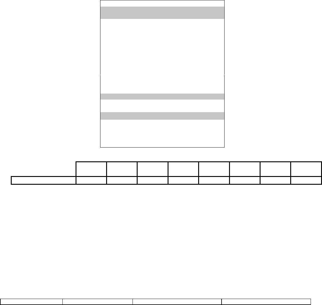
Digital Security Controls Ltd. 68 Private and Confidential
Installation Manual DATE : 09/30/97 DRAFT
[807] ESCORT PROGRAMMING SECTION
[000] Function Key Programmingxxiii
[0] Not Used
[1] Function Key 1 Assignment (Valid entries are 00-30)
[2] Function Key 2 Assignment (Valid entries are 00-30)
[3] Function Key 3 Assignment (Valid entries are 00-30)
[4] Function Key 4 Assignment (Valid entries are 00-30)
[5] Function Key 5 Assignment (Valid entries are 00-30)
[6] Function Key 6 Assignment (Valid entries are 00-30)
[7] Function Key 7 Assignment (Valid entries are 00-30)
[8] Function Key 8 Assignment (Valid entries are 00-30)
00 Null Key (Key Not Used)
01 Not Used
02 Not Used
03 Stay Arm
04 Away Arm
05 [*][9] No Entry Arm
06 [*][4] Chime On / Off
07 [*][6][----][4] System Test
08 [*][1] Bypass Mode
09 [*][2] Trouble Display
10 [*][3] Alarm Memory
11 [*][5] User Programming
12 [*][6] User Functions
13 Not Used
14 Not Used
15 Not Used
16 [*][0] Quick Exit
17 [*][1] Activate Stay/Aways
18-26 Not Used (Reserved)
27 Status (Query)
28 Volume Control
29 Memo Record
30 Memo Playback
Function
Key 1 Function
Key 2 Function
Key 3 Function
Key 4 Function
Key 5 Function
Key 6 Function
Key 7 Function
Key 8
WLS9000 Defaults 03 04 06 16 27 28 29 30
[001] NOT USEDxxiv
[002] FIRST SYSTEM OPTION CODExxv
Default Option ON Option Off
ON I___I Option 01 Clock Is AM/PM Clock is 24 Hour
ON I___I Option 02 Chime Enabled for Zone Openings Door Chime Disabled for Zone Openings
ON I___I Option 03 Chime Enabled for Zone Closings Door Chime Disabled for Zone Closings
OFF I___I Option 04-08 Not Used (For Future Use)

Digital Security Controls Ltd. 69 Private and Confidential
Installation Manual DATE : 09/30/97 DRAFT
[003] STATUS PROMPT MASK
Default Option ON Option Off
ON I___I Option 01 WARNING, BYPASS ON Prompt enabled Prompt disabled
ON I___I Option 02 SYSTEM TROUBLE .... Prompt enabled Prompt disabled
ON I___I Option 03 SYSTEM OPEN, ZONE .... Prompt enabled Prompt disabled
ON I___I Option 04 ALARMS IN MEMORY Prompt enabled Prompt disabled
ON I___I Option 05 SERVICE REQUIRED Prompt enabled Prompt disabled
ON I___I Option 06 AC POWER TROUBLE Prompt enabled Prompt disabled
ON I___I Option 07 PHONE LINE TROUBLE Prompt enabled Prompt disabled
ON I___I Option 08 COMMUNICATION TROUBLE Prompt enab. Prompt disabled
ON I___I Option 09 ZONE FAULT Prompt enabled Prompt disabled
ON I___I Option 10 ZONE TAMPER Prompt enabled Prompt disabled
ON I___I Option 11 ZONE LOW BATTERY Prompt enabled Prompt disabled
ON I___I Option 12 TIME AND DATE INCORRECT Prompt enab. Prompt disabled
[004] STAR FUNCTION PROMPT MASK
Default Option ON Option Off
ON I___I Option 01 FOR ZONE BYPASSING Prompt enabled Prompt disabled
ON I___I Option 02 FOR SYSTEM TROUBLES Prompt enabled Prompt disabled
ON I___I Option 03 FOR ALARM MEMORY Prompt enabled Prompt disabled
ON I___I Option 04 FOR DOOR CHIME CONTROL Prompt enab. Prompt disabled
OFF I___I Option 05 Not Used
ON I___I Option 06 FOR SPECIAL FUNCTIONS Prompt enabled Prompt disabled
OFF I___I Option 07 Not Used
ON I___I Option 08 FOR ARMING WITHOUT ENTRY Prompt enab. Prompt disabled
ON I___I Option 09 FOR QUICK ARMING Prompt enabled Prompt disabled
ON I___I Option 10 FOR QUICK EXIT Prompt enabled Prompt disabled
ON I___I Option 11 TO ARM INTERIOR ZONES Prompt enabled Prompt disabled
ON I___I Option 12 FOR VOLUME CONTROL Prompt enabled Prompt disabled
ON I___I Option 13 FOR SPEECH RATE CONTROL Prompt enab. Prompt disabled
OFF I___I Option 14 Not Used
OFF I___I Option 15 Not Used
ON I___I Option 16 FOR USER PROGRAMMING Prompt enabled Prompt disabled
xxvi
[020] LOCAL/REMOTE PHONE ACCESS CODE
Default
* * * I___II___II___I Enter 3 digits (0,1,2,3,4,5,6,7,8,9,*,#)
WARNING- Avoid Codes that coincide with local telephone company 3-digit telephone numbers and services.
[021] PHONE ACCESS OPTIONS
Default Option ON Option Off
OFF I___I Option 01 Local Access Only Remote and Local Access enabled
OFF I___I Option 02 Code always Req’d for Local Access No code Required for Local Access
[030] ALARM TONE PERIOD FOR VERBAL ALARMxxvii
Default
005 I___II___II___I Valid entries are 001-255 seconds

Digital Security Controls Ltd. 70 Private and Confidential
Installation Manual DATE : 09/30/97 DRAFT
SYSTEM LABEL Default
[561] SYSTEM LABEL _ _ _ _ _ _ _ _ _ _ _ _ _ _ _ _ _ _ System
SYSTEM ZONE LABELS Default
[601] ZONE 1 LABEL _ _ _ _ _ _ _ _ _ _ _ _ _ _ _ _ _ _ Zone 1
[602] ZONE 2 LABEL _ _ _ _ _ _ _ _ _ _ _ _ _ _ _ _ _ _ Zone 2
[603] ZONE 3 LABEL _ _ _ _ _ _ _ _ _ _ _ _ _ _ _ _ _ _ Zone 3
[604] ZONE 4 LABEL _ _ _ _ _ _ _ _ _ _ _ _ _ _ _ _ _ _ Zone 4
[605] ZONE 5 LABEL _ _ _ _ _ _ _ _ _ _ _ _ _ _ _ _ _ _ Zone 5
[606] ZONE 6 LABEL _ _ _ _ _ _ _ _ _ _ _ _ _ _ _ _ _ _ Zone 6
[607] ZONE 7 LABEL _ _ _ _ _ _ _ _ _ _ _ _ _ _ _ _ _ _ Zone 7
[608] ZONE 8 LABEL _ _ _ _ _ _ _ _ _ _ _ _ _ _ _ _ _ _ Zone 8
[609] ZONE 9 LABEL _ _ _ _ _ _ _ _ _ _ _ _ _ _ _ _ _ _ Zone 9
[610] ZONE 10 LABEL _ _ _ _ _ _ _ _ _ _ _ _ _ _ _ _ _ _ Zone 10
[611] ZONE 11 LABEL _ _ _ _ _ _ _ _ _ _ _ _ _ _ _ _ _ _ Zone 11
[612] ZONE 12 LABEL _ _ _ _ _ _ _ _ _ _ _ _ _ _ _ _ _ _ Zone 12
[613] ZONE 13 LABEL _ _ _ _ _ _ _ _ _ _ _ _ _ _ _ _ _ _ Zone 13
[614] ZONE 14 LABEL _ _ _ _ _ _ _ _ _ _ _ _ _ _ _ _ _ _ Zone 14
[615] ZONE 15 LABEL _ _ _ _ _ _ _ _ _ _ _ _ _ _ _ _ _ _ Zone 15
[616] ZONE 16 LABEL _ _ _ _ _ _ _ _ _ _ _ _ _ _ _ _ _ _ Zone 16
[617] ZONE 17 LABEL _ _ _ _ _ _ _ _ _ _ _ _ _ _ _ _ _ _ Zone 17
[618] ZONE 18 LABEL _ _ _ _ _ _ _ _ _ _ _ _ _ _ _ _ _ _ Zone 18
[619] ZONE 19 LABEL _ _ _ _ _ _ _ _ _ _ _ _ _ _ _ _ _ _ Zone 19
[620] ZONE 20 LABEL _ _ _ _ _ _ _ _ _ _ _ _ _ _ _ _ _ _ Zone 20
[621] ZONE 21 LABEL _ _ _ _ _ _ _ _ _ _ _ _ _ _ _ _ _ _ Zone 21
[622] ZONE 22 LABEL _ _ _ _ _ _ _ _ _ _ _ _ _ _ _ _ _ _ Zone 22
[623] ZONE 23 LABEL _ _ _ _ _ _ _ _ _ _ _ _ _ _ _ _ _ _ Zone 23
[624] ZONE 24 LABEL _ _ _ _ _ _ _ _ _ _ _ _ _ _ _ _ _ _ Zone 24
[625] ZONE 25 LABEL _ _ _ _ _ _ _ _ _ _ _ _ _ _ _ _ _ _ Zone 25
[626] ZONE 26 LABEL _ _ _ _ _ _ _ _ _ _ _ _ _ _ _ _ _ _ Zone 26
[627] ZONE 27 LABEL _ _ _ _ _ _ _ _ _ _ _ _ _ _ _ _ _ _ Zone 27
[628] ZONE 28 LABEL _ _ _ _ _ _ _ _ _ _ _ _ _ _ _ _ _ _ Zone 28
[629] ZONE 29 LABEL _ _ _ _ _ _ _ _ _ _ _ _ _ _ _ _ _ _ Zone 29
[630] ZONE 30 LABEL _ _ _ _ _ _ _ _ _ _ _ _ _ _ _ _ _ _ Zone 30
[631] ZONE 31 LABEL _ _ _ _ _ _ _ _ _ _ _ _ _ _ _ _ _ _ Zone 31
[632] ZONE 32 LABEL _ _ _ _ _ _ _ _ _ _ _ _ _ _ _ _ _ _ Zone 32
[633] FIRE ALARM LABEL _ _ _ _ _ _ _ _ _ _ _ _ _ _ _ _ _ _ Fire Zone
Note: Zone Labels are also Programmed Via the Wizard!

Digital Security Controls Ltd. 71 Private and Confidential
Installation Manual DATE : 09/30/97 DRAFT
Custom Label Record Section
When in one of the following sections, press ‘Record’ (Function Key 7) to begin recording, and ‘Playback’ (Function
Key 8) to end the recording an annunciate the label. ‘Playback’ can be pressed several times to re-annunciate the
Label recording.
Note: Even if Function Keys 7 and 8 have been reprogrammed, they will still retain the same above functions in
these sections.
[701] RECORD CUSTOM LABEL #1
[702] RECORD CUSTOM LABEL #2
[703] RECORD CUSTOM LABEL #3
[704] RECORD CUSTOM LABEL #4
[705] RECORD CUSTOM LABEL #5
[706] RECORD CUSTOM LABEL #6
[707] RECORD CUSTOM LABEL #7
[708] RECORD CUSTOM LABEL #8

Digital Security Controls Ltd. 72 Private and Confidential
Installation Manual DATE : 09/30/97 DRAFT
ESCORT5580 Label Library
[000] ( Combined # Command ) [062] ELEVATOR [124] LIGHT [186] SCHEDULE
[001] ( Ordered # Command ) [063] EMPLOYEE [125] LIGHTS [187] SENSOR
[002] ( Individual # Command ) [064] ENERGY-SAVE [126] LIQUOR [188] SERVICE
[003] ACCESS [065] ENTERTAINMENT [127] LIVING [189] SHED
[004] AIR-CONDITIONING [066] ENTRY [128] LOADING [190] SHIPPING
[005] ALCOVE [067] EQUIPMENT [129] LOBBY [191] SHOP
[006] AND [068] EXERCISE [130] LOT [192] SHUTTER
[007] APARTMENT [069] EXHAUST [131] LOW [193] SIDE
[008] APPLIANCE [070] EXIT [132] LOWER [194] SILENT
[009] AREA [071] EXTERIOR [133] MACHINE [195] SKYLIGHT
[010] ATRIUM [072] EXTINGUISHER [134] MAIDS [196] SLIDING
[011] ATTIC [073] FACTORY [135] MAIL [197] SMOKE
[012] AUTOMATIC [074] FAMILY [136] MAIN [198] SOLARIUM
[013] AWAY [075] FAN [137] MAINTENANCE [199] SOUNDER
[014] BACK [076] FENCE [138] MASTER [200] SOUTH
[015] BACKYARD [077] FILE [139] MAT [201] SPRINKLER
[016] BALCONY [078] FIRE * [140] MEDICAL [202] STAFF
[017] BAR [079] FLOOR [141] MEETING [203] STAIRS
[018] BARN [080] FLORIDA [142] MEN'S [204] STEREO
[019] BASEMENT [081] FLOW [143] MIDDLE [205] STOCK
[020] BATHROOM [082] FOIL [144] MODE * [206] STORAGE
[021] BAY [083] FOUNTAIN [145] MOTION [207] STRIKE
[022] BEAM [084] FOYER [146] NIGHT [208] SUMP
[023] BEDROOM [085] FREEZER [147] NORTH [209] SUPERVISION
[024] BLINDS [086] FRENCH [148] NUMBER [210] SWIMMING-POOL
[025] BOAT [087] FRONT [149] NURSERY [211] SYSTEM *
[026] BOILER [088] FURNACE [150] OFFICE [212] TAMPER
[027] BOTTOM [089] GAME [151] OUTER [213] TELEVISION
[028] BOYS [090] GARAGE [152] OUTLET [214] TEMPERATURE
[029] BUILDING [091] GARBAGE [153] OUTPUT * [215] TIME
[030] CABINET [092] GAS [154] OVER [216] TOOL
[031] CAFETERIA [093] GATE [155] OVERFLOW [217] TOP
[032] CAMERA [094] GIRLS [156] OVERHEAD [218] TRACK
[033] CASH [095] GLASSBREAK [157] PANEL [219] TRAP
[034] CEILING [096] GREENHOUSE [158] PANIC-BUTTON [220] UNDER
[035] CENTER [097] GROUND [159] PARKING [221] UNIT
[036] CHANGEROOM [098] GUARD [160] PARTITION * [222] UP
[037] CHINA [099] GUEST [161] PATIO [223] UPPER
[038] CIRCUIT [100] GUN [162] PERIMETER [224] UTILITY
[039] CLASSROOM [101] GYM [163] PHOTOCOPIER [225] VAULT
[040] COFFEE-MAKER [102] HALLWAY [164] PICTURE [226] VENT
[041] COLD [103] HEAT [165] PLACE [227] VIBRATION
[042] COLLECTION [104] HEATER [166] PLAY [228] WALKWAY
[043] COMPRESSOR [105] HIGH [167] PORCH [229] WAREHOUSE
[044] COMPUTER [106] HOLIDAY [168] PORTABLE [230] WASHROOM
[045] CONTACT [107] HOME [169] POWER [231] WATER
[046] CONTROL * [108] HOSE [170] PRESSURE [232] WEEKEND
[047] CRAWL-SPACE [109] HOT TUB [171] PROXIMITY [233] WELL
[048] CURTAIN [110] HOUSE [172] PULL-STATION [234] WEST
[049] DARK [111] HUMIDITY [173] PUMP [235] WINDOW
[050] DAY [112] INTERIOR [174] RAMP [236] WINE-CELLAR
[051] DECK [113] INTRUSION [175] REAR [237] WORK
[052] DEGREES [114] ITEM * [176] RECEIVING [238] YARD
[053] DEN [115] JEWELRY [177] RECREATION [239] ZONE *
[054] DETECTOR [116] KITCHEN [178] REFRIGERATOR [240] THERMOSTAT *
[055] DINING [117] LADIES' [179] RESET [241] Not Used
[056] DISHWASHER [118] LAMP [180] RESTRICTED [242] Not Used
[057] DOOR [119] LAUNDRY [181] RIGHT [243] Not Used
[058] DOWN [120] LAWN [182] ROOF [244] Not Used
[059] DRIVEWAY [121] LEFT [183] ROOM [245] (2 Second Pause)
[060] EAST [122] LEVEL [184] SAFE [246] Custom Record #1
[061] ELECTRIC [123] LIBRARY [185] SAUNA [247] Custom Record #2
[248] Custom Record #3
[249] Custom Record #4
[250] Custom Record #5
[251] Custom Record #6
[252] Custom Record #7
[253] Custom Record #8

Digital Security Controls Ltd. 73 Private and Confidential
Installation Manual DATE : 09/30/97 DRAFT
ESCORT System Words
AC FAULT NOT SEVEN
ALARM FOR / FOUR NOW SECOND
ALARMS FROM NINE SUNDAY
ALL FLUID NOVEMBER SATURDAY
AN FIVE NEGATIVE SEPTEMBER
ARE FIF OF STAY
ATTENTION FAULTS OFF SETTING
AUTOMATION FUNCTIONS ON THE
A.M. FRIDAY OPEN THEN
AUTO FUNCTION OPTION THERE
ARMING FEBRUARY OPTIONS TEEN
ANY FAHRENHEIT OVER TROUBLE
ACTIVE GLOBAL OVERFLOW TURN
AUDIO GOODBYE OVERHEAD TURNING
APRIL GRANTED ONE TO / TWO
AUGUST HAVE OH THREE
ASTERISK HELLO OR TEN
AVAILABLE HAS OCTOBER TWELVE
AGAIN HUNDRED O’CLOCK TY
AUXILIARY HELP OCCUPANCY THIR
BATTERY IN PHONE TWENTY
BEFORE INCOMING POUND THOUSAND
BYPASS INCORRECT PRESENT TH
BYPASSED INDIVIDUAL PRESS TROUBLES
BYPASSING INVALID PREVIOUS TUESDAY
BEEN IS PROGRESS THURSDAY
BUSY ITEMS P.M. THIS
BABY INTRUSION PARTITIONS TEST
CALL ITH PLEASE TWENTY - FOUR - HOUR
CHANGE INCREASE PROGRAMMING TRY
CHIME INPUT PROGRAMMED TRANSMITTERS
CLOSE JANUARY PROCEEDING THIRD
CODE JUNE QUICK THERMOSTAT
COMPLETE JULY RATE UNABLE
CLEAR KEY RECEIVE USING
CLEARED KEYBUS REQUIRED USER
CARPORT KEYPAD READY USERS
COATROOM KEYS RECALL USE
CANCEL KEYPADS RECALLED VOLUME
CHECK LINE REMOVE VACUUM
COMMUNICATION LOCKOUT RETURNED WARNING
CHUTE LAST REST - ROOM WITHOUT
CELSIUS LIST RD WORD
COOL LABORATORY REMOTE WEEK
DATA LANDSCAPE RETURN WEDNESDAY
DATE LOG SECTION WALK
DELAY LATER SECURE WIRELESS
DENIED MEDIUM SELECT YEAR
DIGIT MEMORY SELECTION YOU
DIGITS MONTH SERVICE YOUR
DOOR MACHINE SETBACK ZONES
DEFAULT MORE SLOW ZERO
DECREASE MONDAY SPECIAL
DECEMBER MUSIC SPEECH
DEVICES MARCH STAR
DEVICE MAY SAFE
ENTER MESSAGE SCHEDULED
EIGHT NEW SET
ELEVEN NEXT SPECIAL - FUNCTIONS
FAST NO SIX

Digital Security Controls Ltd. 74 Private and Confidential
Installation Manual DATE : 09/30/97 DRAFT
SPECIAL INSTALLER FUNCTIONS
[901] INSTALLER WALK TEST MODE ENABLE / DISABLE
NOTES: Walk Test should always be entered from the normal state ([*][8][INS Code][901]).
Fire Troubles are not supported in Walk Test.
The option “Fire Bell is Continuous” should not be used in Walk Test.
[904] WIRELESS MODULE PLACEMENT TEST
[990][Installer’s Code][990] INSTALLER LOCKOUT ENABLE
• ENTER [990] [INSTALLER’S CODE] [990]
[991][Installer’s Code][991] INSTALLER LOCKOUT DISABLE
• ENTER [991] [INSTALLER’S CODE] [991]
[992][Installer’s Code][992] RESTORE MAIN CONTROLLER DEFAULT PROGRAMMING
• ENTER [992] [INSTALLER’S CODE] [992]
[995][Installer’s Code][995] RESTORE ESCORT FACTORY DEFAULT PROGRAMMING
• ENTER [995] [INSTALLER'S CODE] [995]
[996][Installer’s Code][996] RESTORE RF FACTORY DEFAULT PROGRAMMING
• ENTER [996] [INSTALLER’S CODE] [996]
[999][Installer’s Code][999] RESTORE ALL WLS9000 FACTORY DEFAULT PROGRAMMINGxxviii
• ENTER [999] [INSTALLER’S CODE] [999]

Digital Security Controls Ltd. 75 Private and Confidential
Installation Manual DATE : 09/30/97 DRAFT
15.0 Document Revision Endnotes
Note # Revision Section Changes
i 1.01 Section 4.3 Added new plastic numbers for Deflector and interface plate.
ii 1.01 Section 4.3 Added the Acuity microphone shroud to the Plastic section.
iii 1.01 Section 5.2.1 Elaborated on Status.
iv 1.01 Section 5.2.1 Elaborated on the Volume Function Key.
v 1.01 Section 5.2.2.2 Removed “TBD” and replaced with “no presets” for the label
programming of the Panic Pendant.
vi 1.01 Section 5.2.8 Changed section of Alarm Tone Period to Section [807], Sub [030].
vii 1.01 Section 5.2.13 Added Function Key Programming in the ESCORT.
viii 1.01 Section 5.2.14 Added new log for Module Placement Test Unsuccessful.
ix 1.01 Section 8.1 Changed Hardware Default to use Green to Black.
x 1.01 Section 8.2.1 Removed Zone Definitions 7 and 8.
xi 1.01 Section 8.2.6 Redefined the Hardwired Zone Loops’ location/programming.
xii 1.01 Section 8.2.7 Updated the Annunciation Options.
xiii 1.01 Section 8.2.9 Changed the Wireless Bit = OFF to Not Used.
xiv 1.01 Section 8.2.18 Added function key programming.
xv 1.01 Section 8.2.17 Exchanged Sections 992 and 999 (999 now defaults all; 992
defaults the Controller).
xvi 1.01 Section 9.1 Changed the DLS-3 version from v1.10 to v1.20; added the Driver
Pack, and removed DLS-1 support.
xvii 1.01 Section 10.0 Moved Function Key Programming.
xviii 1.01 Section 10.0 Local and Remote Annunciation has been moved from Section
[040] to Section [017].
xix 1.01 Section 10.0 Made Zone Definitions 7 and 8 not used.
xx 1.01 Section 10.0 Removed redundant Not Used Reporting Codes.
xxi 1.01 Section 10.0 Restructured the Handheld Keypad/WLSKey Function Key Options.
xxii 1.01 Section 10.0 Changed Hardwired Zone Programming from the main
programming into Section [804].
xxiii 1.01 Section 10.0 Moved Function Key Programming to the ESCORT (Section [807]).
xxiv 1.01 Section 10.0 Removed Service Code.
xxv 1.01 Section 10.0 Removed [*][5] access and System Access; moved Clock Options
to Bit 1; added Door Chime Control.
xxvi 1.01 Section 10.0 Removed Programming Lockout Count and Duration.
xxvii 1.01 Section 10.0 Moved Alarm Tone Period feature to the ESCORT (Section [030]).
xxviii 1.01 Section 10.0 Exchanged Sections 992 and 999 (999 now defaults all; 992
defaults the Controller).