Tyco Safety Sensormatic AMB44 WIRELESS LR-WPAN IN 2.4 GHz BAND USING DIGITAL SS. User Manual ZBAMB2070 Handheld Mobile Deactivator 8200 0958 01
Tyco Safety Products/Sensormatic WIRELESS LR-WPAN IN 2.4 GHz BAND USING DIGITAL SS. ZBAMB2070 Handheld Mobile Deactivator 8200 0958 01
Contents
- 1. Install Guide
- 2. User Guide 1B
- 3. User Guide
Install Guide
PRELIMINARY
ZBAMB2070 MOBILE HANDHELD DEACTIVATOR 8200-0958-01, REV. 1B
USER GUIDE 1 of 16
ZBAMB2070 Mobile
Handheld Deactivator
(Motorola MT2070 Handheld Scanner)
Installation Guide
IMPORTANT! Before You Begin!
This device contains many unique parts.
Before you go to the installation site,
watch the Mobile Handheld Deactivator
training video on the LMS site at
https://mytycohr.com, or on Yammer “Tyco
Retail Solutions Global Training Group” at
https://www.yammer.com/tyco.com.
Contents
Required Parts and Tools ...................................... 2
Installation .............................................................. 3
Troubleshooting ................................................... 13
Maintain the Product ............................................ 14
Specifications ....................................................... 15
Declarations ......................................................... 16
Note: Because customer requirements may dictate
the placement of specific components, your
Sensormatic representative will supply this
information separately.
© 2013 Sensormatic Electronics, LLC
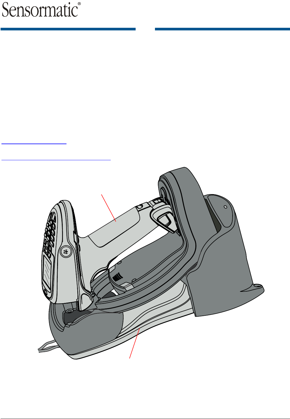
Motorola MT2070
Handheld Scanner
ZBAMB2070 EAS
Deactivator Module
Assembly (dark
shaded parts)
Motorola MT2070
Base Charging Station
PRELIMINARY
ZBAMB2070 MOBILE HANDHELD DEACTIVATOR 8200-0958-01, REV. 1B
USER GUIDE 2 of 16
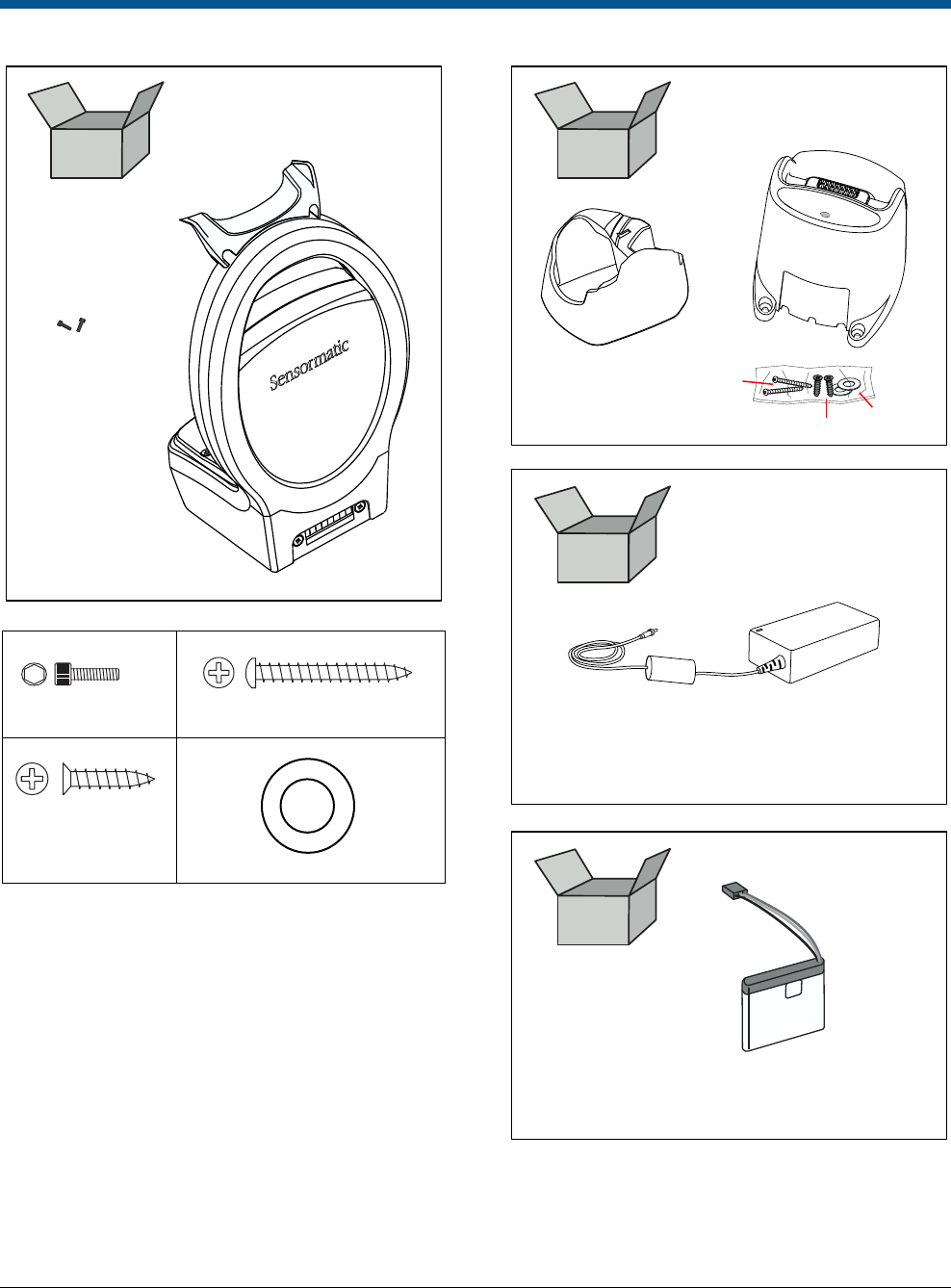
Required Parts and Tools
EAS Power Supply 5606-0096-01
(plus 0352-0460-xx power cord)
S3
S2
W
ZBAMB4415
EAS Module
Front Adapter
EAS Module
Rear Adapter
S1 (2x)
ZBAMB4410
EAS
Deactivator
Module
S1 (2x)
S3 (2x)
W (2x)
S2 (2x)
Lithium Battery Kit 0352-0594-01
(3.7V, 2.2Ah, with leads)
2 in a box
PRELIMINARY
ZBAMB2070 MOBILE HANDHELD DEACTIVATOR 8200-0958-01, REV. 1B
USER GUIDE 3 of 16
Installation
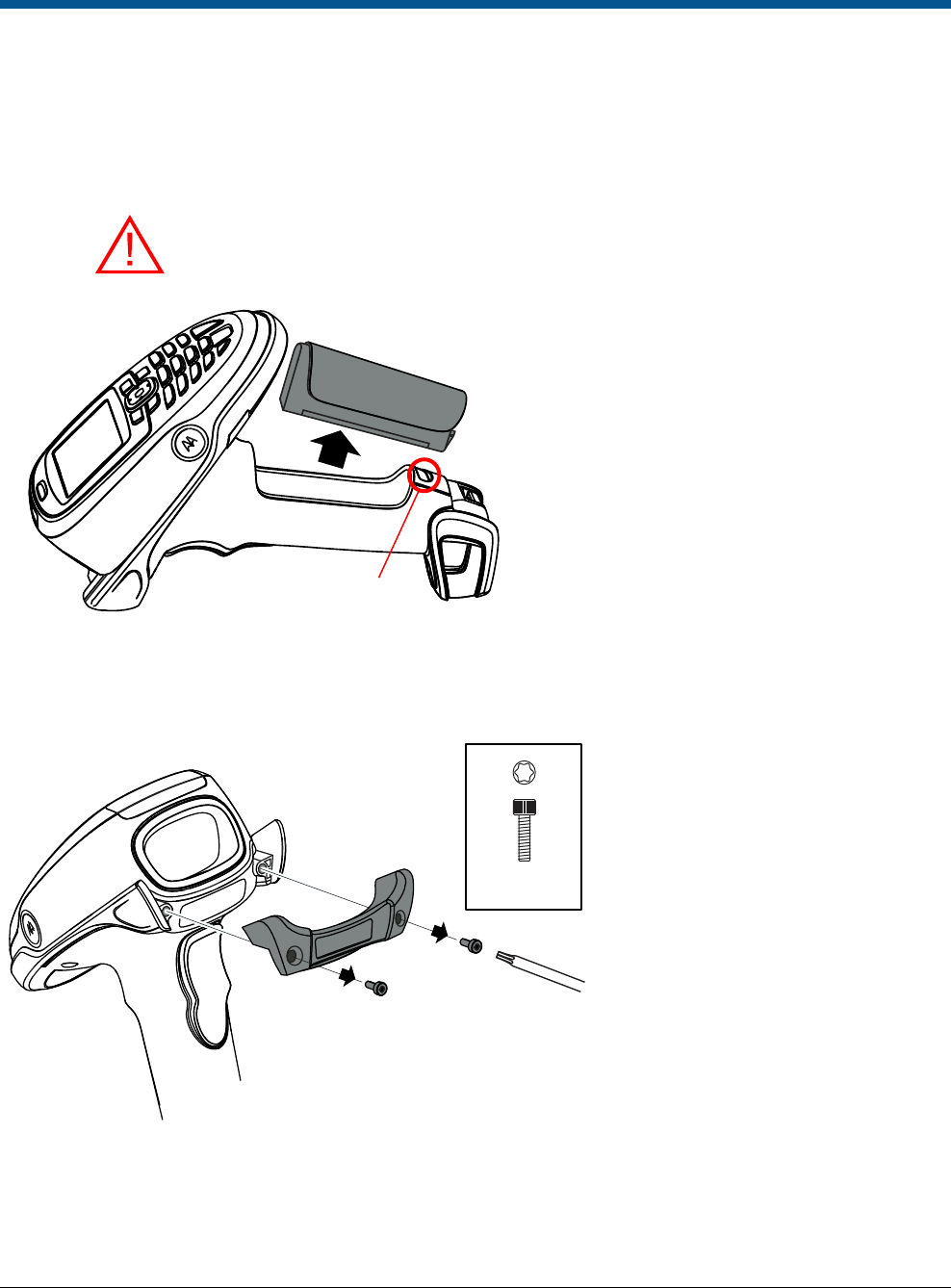
Step 1. Prepare the Motorola scanner gun
1a
1b
Scanner Gun
Use a T8x60 Torx wrench to remove the
Motorola MT2070 bumper (save parts to
give later to Loss Prevention Manager).
T8x60 (2x)
Press and slide
switch to release.
Save the battery. You will
re-install it at the end of this
procedure.
WARNING: Remove the battery to prevent accidental
exposure to laser radiation during assembly.
PRELIMINARY
ZBAMB2070 MOBILE HANDHELD DEACTIVATOR 8200-0958-01, REV. 1B
USER GUIDE 4 of 16
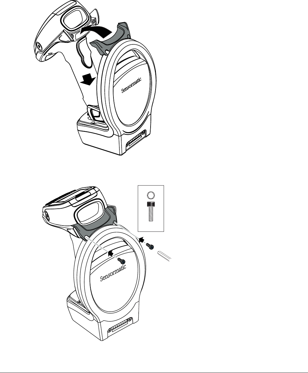
Step 2. Attach the scanner gun to the EAS Deactivator Module
2a
2b
Tight fit. Apply moderate
pressure to secure.
2. Press in place.
1. Push down.
S1 (2x)
Use a 3/32in hex wrench.
PRELIMINARY
ZBAMB2070 MOBILE HANDHELD DEACTIVATOR 8200-0958-01, REV. 1B
USER GUIDE 5 of 16
Remove the
Motorola interlock
and power supply
cables.
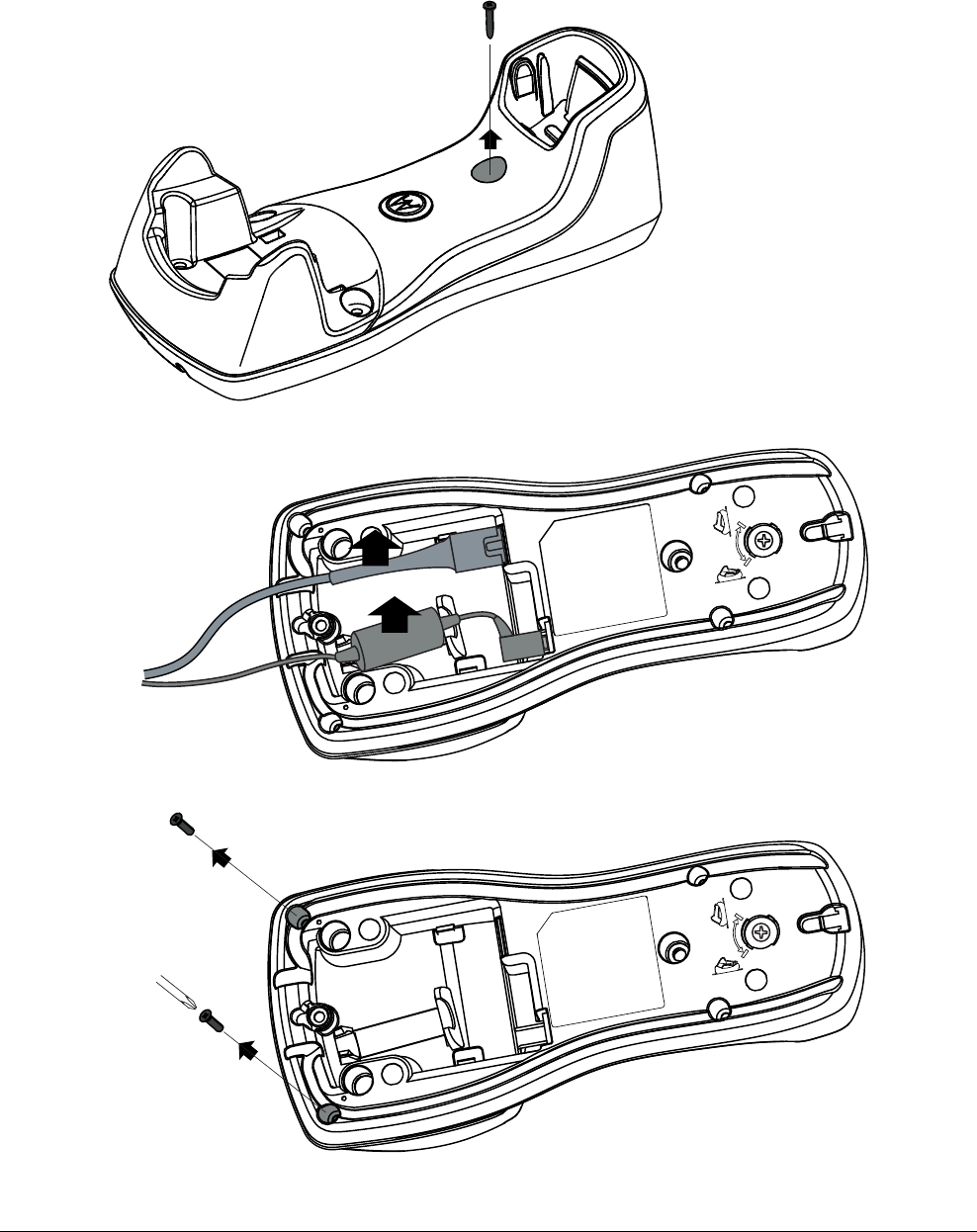
Step 3. Prepare the Motorola Base Charging Station
3a
3b
3c
2x
Remove and
save screws.
Re-install in
Step 4c.
Detach the Motorola Base
Charging Station from the
counter by removing the center
screw and/or Velcro, if any.
PRELIMINARY
ZBAMB2070 MOBILE HANDHELD DEACTIVATOR 8200-0958-01, REV. 1B
USER GUIDE 6 of 16
Step 4. Modify the Motorola Base Charging Station (Part 1)
4a
4b
4c
Install the ZBAMB4415 EAS Front Adapter.
Squeeze tabs to detach the
Motorola Front Adapter. Give the
part to the Loss Prevention
Manager.
2x
Secure EAS Front Adapter by reinstalling
screws removed in Step 3c.
PRELIMINARY
ZBAMB2070 MOBILE HANDHELD DEACTIVATOR 8200-0958-01, REV. 1B
USER GUIDE 7 of 16
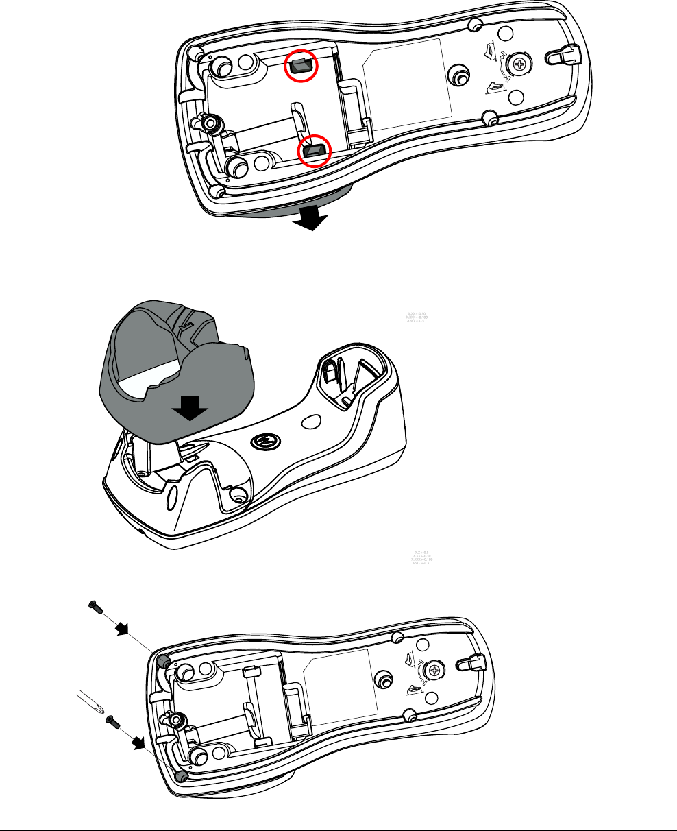
Step 5. Modify the Motorola Base Charging Station (Part 2)
5a
5b
Turn the locking screw
counter-clockwise.
Press the ZBAMB4415 EAS Rear
Adapter onto the Motorola Base
Charging Station until it “clicks”.
Note: Leave the locking screw in
its counter-clockwise position.
PRELIMINARY
ZBAMB2070 MOBILE HANDHELD DEACTIVATOR 8200-0958-01, REV. 1B
USER GUIDE 8 of 16
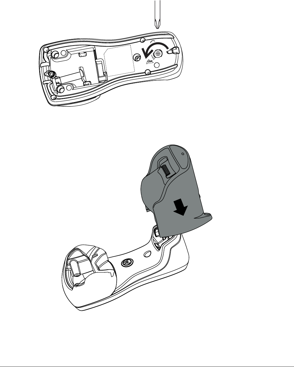
Modify the Motorola Base Charging Station (Part 2), continued
5c
5d
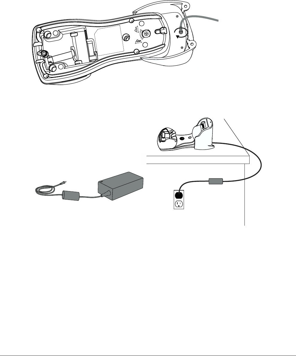
Plug the EAS Power supply
into a protected AC outlet.
5606-0096-01 EAS
Power Supply
Thread the EAS power supply cable into
the bottom of the EAS Rear Adapter.
PRELIMINARY
ZBAMB2070 MOBILE HANDHELD DEACTIVATOR 8200-0958-01, REV. 1B
USER GUIDE 9 of 16
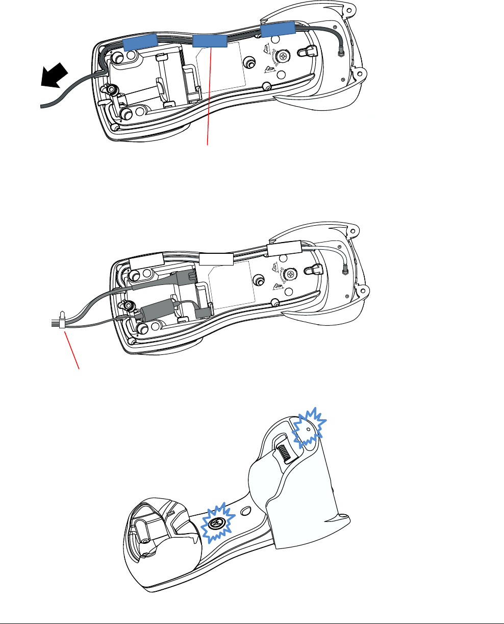
Step 6. Modify the Motorola Base Charging Station (Part 3)
6a
6b
6c
Motorola
(Blue LED)
EAS
(Blue LED)
Verify that power is supplied
to both the deactivator
module and to the Motorola
Base Charging Station.
Route the EAS power supply cable
through the cable channel in the
Motorola Base Charging Station.
Tape cables in place
where shown.
Re-connect the Motorola
interlock and power
supply cables.
Tie wrap cables
PRELIMINARY
ZBAMB2070 MOBILE HANDHELD DEACTIVATOR 8200-0958-01, REV. 1B
USER GUIDE 10 of 16
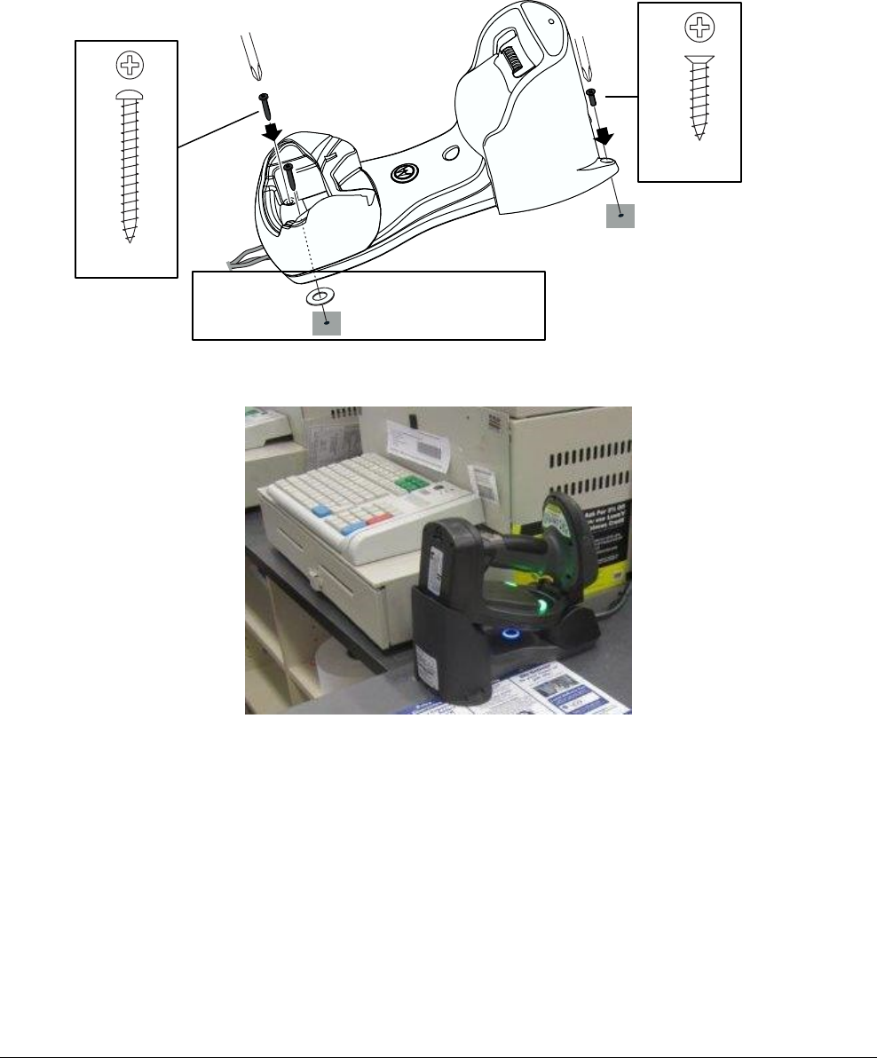
Step 7. Secure the Motorola Base Charging Station
Example of Mounting Location
A mounting plate may be required if the mounting surface is
uneven. Order Mounting Plate Kit 0352-0588-01.
In the order shown, secure the Base Charging
Station at the customer’s preferred location
(see example below). Secure the front adapter
first, then the rear adapter.
W (2x)
Use to level the base
charging station.
1.
S2 (2x)
2.
S3 (2x)
3.
PRELIMINARY
ZBAMB2070 MOBILE HANDHELD DEACTIVATOR 8200-0958-01, REV. 1B
USER GUIDE 11 of 16
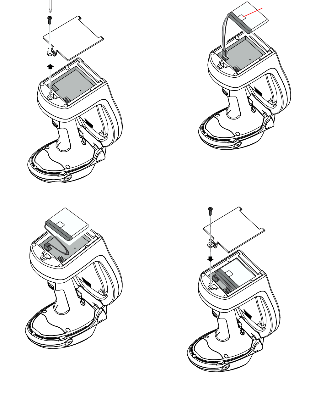
Step 8. Install the EAS battery
8a
8c
8d
8b
Holding the battery
with its barcode
label facing up, plug
in the battery cable.
Barcode label
Bend wires
as shown.
Remove the
screw and
battery cover.
Install the
battery cover
and secure
with the screw.
DO NOT over
tighten.
PRELIMINARY
ZBAMB2070 MOBILE HANDHELD DEACTIVATOR 8200-0958-01, REV. 1B
USER GUIDE 12 of 16
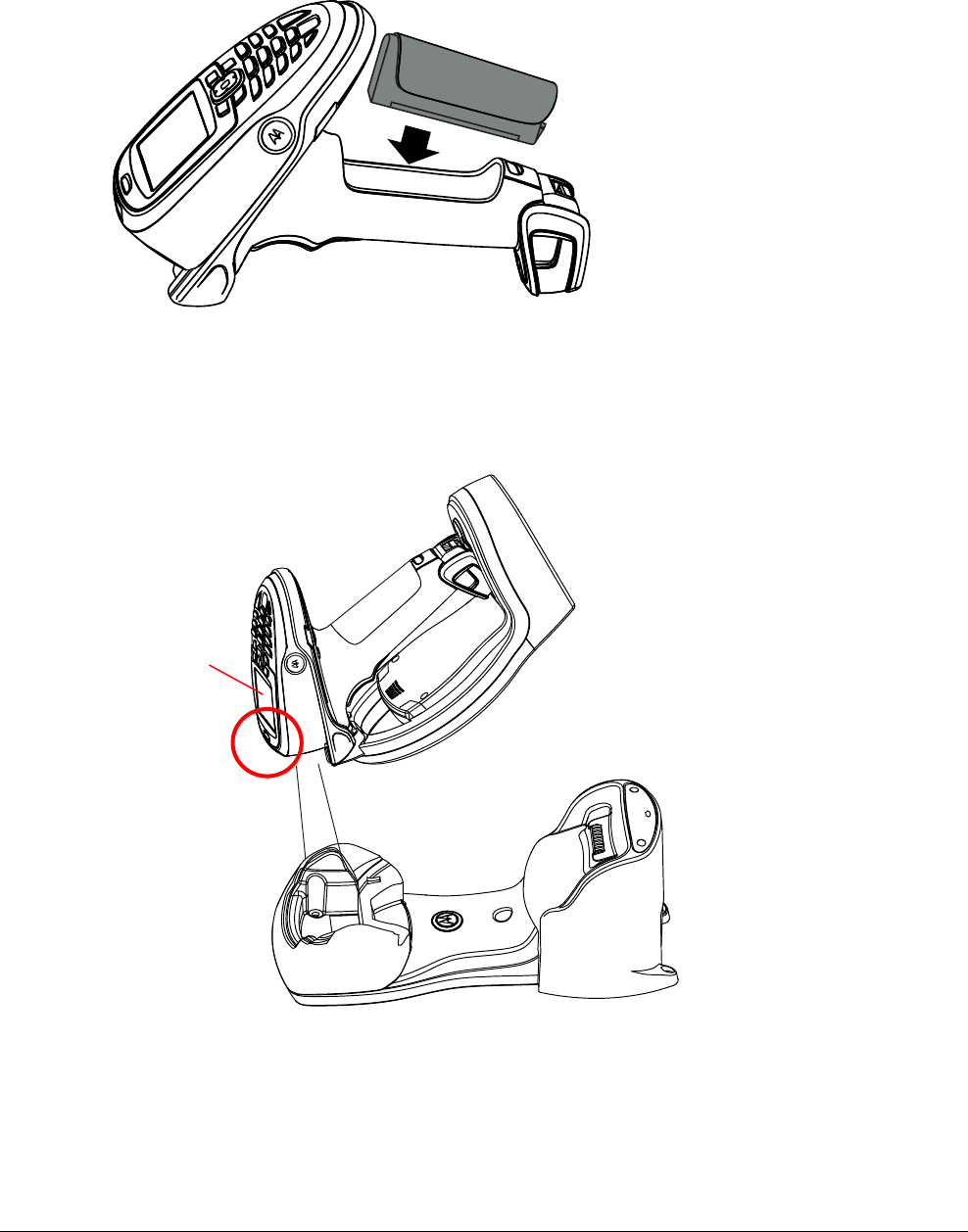
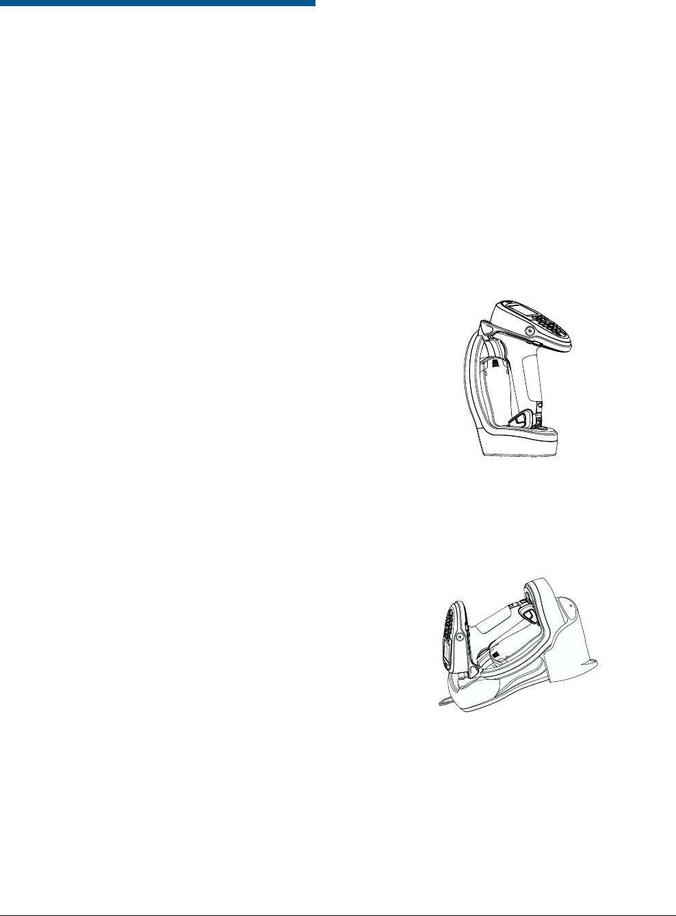
Step 9. Re-install the battery into the Motorola scanner gun
Step 10. Pair the scanner gun to the Base Charging Station
Scan the barcode on the
Motorola Base Charging
Station to pair the scanner.
LED/Audio sequence:
Red > Beep > Green.
Look for lightning bolt
symbol on the LCD.
PRELIMINARY
ZBAMB2070 MOBILE HANDHELD DEACTIVATOR 8200-0958-01, REV. 1B
USER GUIDE 13 of 16
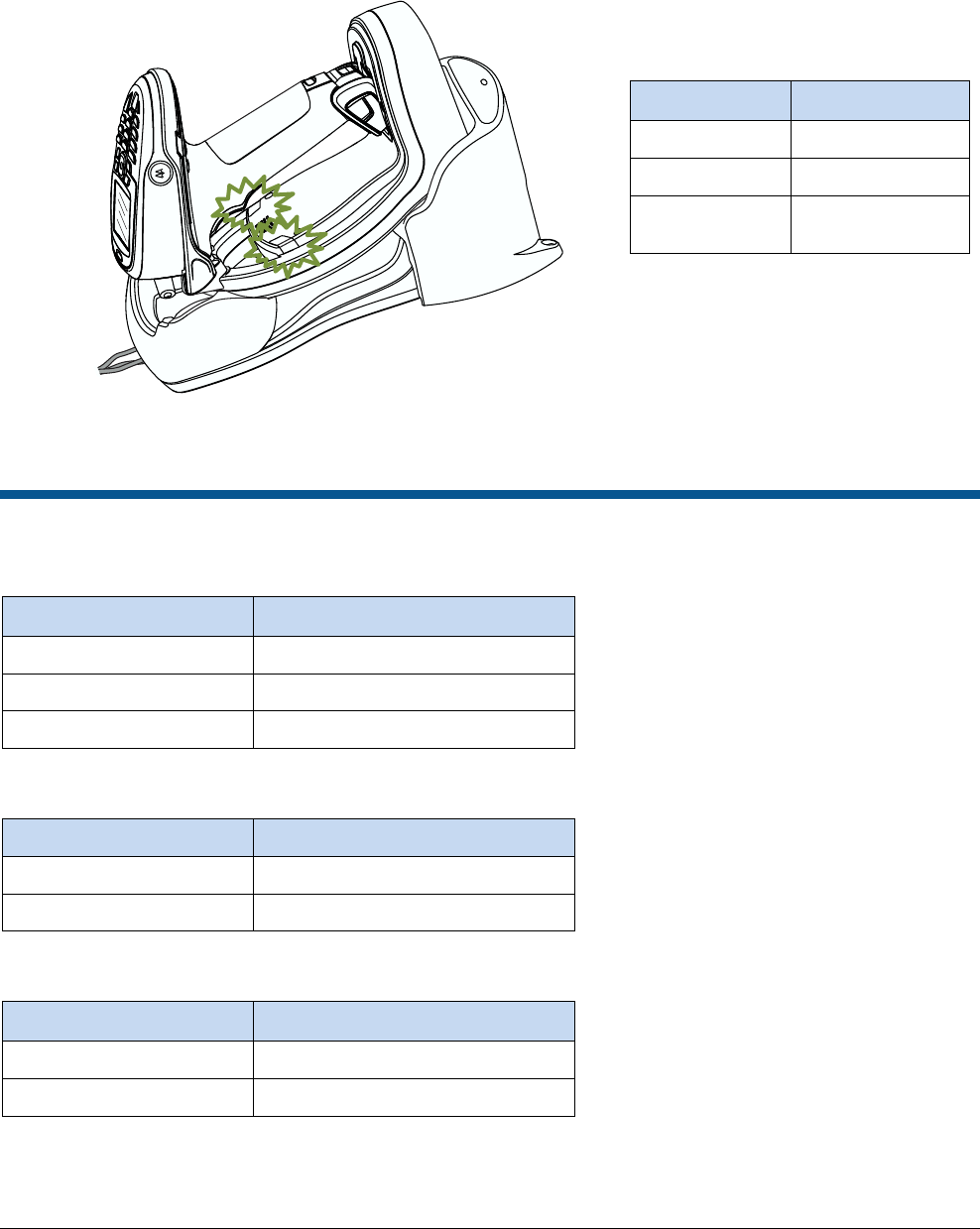
Step 11. Charge the battery in the EAS Deactivator Module
Troubleshooting
ZBAMB4410 Deactivator
LEDs / Audio
Indicates
Fast flashing red
Replace battery
Slow flashing red + beep
Module is out of range of wireless AP
Solid red
Replace module
Motorola Base Charging Station
LED
Indicates
Dim Blue
No communication
Off
No power
MT2070 Scanner
LCD
Indicates
Lightning bolt
Charging
No lightning bolt
No power
Charge for 8 hours
before first use.
Deactivator Charging Indications
LEDs
Indicates
Flashing green
Charging
Solid green
Fully charged
Off
Module not in base
and sync’d with AP

PRELIMINARY
ZBAMB2070 MOBILE HANDHELD DEACTIVATOR 8200-0958-01, REV. 1B
USER GUIDE 14 of 16
Maintain the Product
Field Replaceable Parts
A complete parts list is available online at:
http://www.sensormatic.com/support/techsupport/.
Login, then click the Part Information link on the
Tech Support home page.
Part
Number
ZBAMB4410
EAS Deactivator Module
ZBAMB4415
EAS Module Rear Adapter
5606-0096-01
Power Supply, EAS Module
Rear Adapter
0352-0460-xx
Power Cord, Power Supply,
EAS Module Rear Adapter
PRELIMINARY
ZBAMB2070 MOBILE HANDHELD DEACTIVATOR 8200-0958-01, REV. 1B
USER GUIDE 15 of 16
Specifications
Electrical
AC input ........................................ 100–240V @ 47-63Hz
DC Input ................................................... 12Vdc @ 2.5A
Deactivator Charging Station
DC input .................................................... 12Vdc @ 2.5A
Communications ....................................... Pass-thru data
Power on indicator ............................................ Blue LED
Mobile Handheld Deactivator
Deactivation range ........................ 11.4–15.2cm (4.5–6in)
Communications
Power on indicator ............................................ Blue LED
Display ................................................. Scanner has LCD
Data communication:
Wireless .......................................................... 802.15.4
Data rate ........................................................ 250Kbps
Frequency range ............................. 2.4GHz ISM band,
2405MHz–2480MHz
Output power............ 5mW, +7dBm Max. (boost mode)
Spreading technique .............. Direct Sequence Spread
Spectrum (DSSS)
EAS synchronization ............................... Wireless EAS
Sync-AP transceiver
Under Industry Canada regulations, this radio transmitter may
only operate using an antenna of a type and maximum (or
lesser) gain approved for the transmitter by Industry Canada.
To reduce potential radio interference to other users, the
antenna type and its gain should be so chosen that the
equivalent isotropically radiated power (e.i.r.p.) is not more than
that necessary for successful communication.
Conformément à la réglementation d’Industrie Canada, le
présent émetteur radio peut fonctionner avec une antenne d’un
type et d’un gain maximal (ou inférieur) approuvé pour
l’émetteur par Industrie Canada.
Dans le but de réduire les risques de brouillage radioélectrique
à l’intention des autres utilisateurs, il faut choisir le type
d’antenne et son gain de sorte que la puissance isotrope
rayonnée équivalente (p.i.r.e.) ne dépasse pas l’intensité
nécessaire à l’établissement d’une communication satisfaisante.
Antenna: 2.4GHz Internal (inverted F type PCB trace)
Battery
Battery type ................. Rechargeable lithium ion polymer
2200 mAh (max. 4.3V, nominal 3.7V)
Operating temperature ................ 32 to 122°F (0 to 50°C)
Storage temperature ............... -40 to 158°F (-40 to 70°C)
Charging temp. ............. 32 to 104°F (0 to 40°C) nominal
41 to 95°F (5 to 35°C) ideal
Environmental
Operating, storage, and
charging temperature .................................. See “Battery”
Relative humidity ...................... 0 to 85% non-condensing
Mechanical
Scanner/Deactivator only (standing):
Length ..................................................... 14.9cm (5.88in)
Width ......................................................... 11.4cm (4.5in)
Height ........................................................... 22.9cm (9in)
Weight ..................................................... 0.9kg (1.93 lbs)
Scanner/Deactivator sitting in Base Charging Station:
Length ................................................... 27.3cm (10.75in)
Width ......................................................... 11.4cm (4.5in)
Height ........................................................... 20.3cm (8in)

PRELIMINARY
ZBAMB2070 MOBILE HANDHELD DEACTIVATOR 8200-0958-01, REV. 1B
USER GUIDE 16 of 16
Declarations
Regulatory Information
FCC ID: BVCAMB44
NOTE: This equipment has been tested and found to comply
with the limits for a Class B digital device, pursuant to part 15 of
the FCC Rules. These limits are designed to provide reasonable
protection against harmful interference in a residential
installation. This equipment generates, uses and can radiate
radio frequency energy and, if not installed and used in
accordance with the instructions, may cause harmful
interference to radio communications. However, there is no
guarantee that interference will not occur in a particular
installation. If this equipment does cause harmful interference to
radio or television reception, which can be determined by
turning the equipment off and on, the user is encouraged to try
to correct the interference by one or more of the following
measures: reorient or relocate the receiving antenna, increase
the separation between the equipment and receiver, connect
the equipment into an outlet on a circuit different from that to
which the receiver is connected, and/or consult the dealer or an
experienced radio/TV technician for help.
IC ID: 3506A-AMB44
MODELS: ZBAMB2070
This device complies with Industry Canada licence-exempt RSS
standard(s). Operation is subject to the following two conditions:
(1) this device may not cause interference, and (2) this device
must accept any interference, including interference that may
cause undesired operation of the device.
Le présent appareil est conforme aux CNR d’Industrie Canada
applicables aux appareils radio exempts de licence.
L’exploitation est autorisée aux deux conditions suivantes : (1)
l’appareil ne doit pas produire de brouillage, et (2) l’utilisateur de
l’appareil doit accepter tout brouillage radioélectrique subi,
même si le brouillage est susceptible d’en compromettre le
fonctionnement.
This Class B digital apparatus complies with Canadian ICES-
003.
Cet appareil numérique de la classe B est conforme à la norme
NMB-003 du Canada.
EMC ........................................................ 47 CFR, Part 15
ICES-003
RSS-Gen
RSS-210
Safety ................................. UL 60950-1 (second edition)
CSA C22.2.60950-1
EN 60950-1
Environmental rating ................................................. IP54
EQUIPMENT MODIFICATION CAUTION: Equipment changes
or modifications not expressly approved by Sensormatic
Electronics, LLC, the party responsible for FCC compliance,
could void the user’s authority to operate the equipment and
could create a hazardous condition.
Other Declarations
WARRANTY DISCLAIMER: Sensormatic Electronics, LLC
makes no representation or warranty with respect to the
contents hereof and specifically disclaims any implied
warranties of merchantability or fitness for any particular
purpose. Further, Sensormatic Electronics, LLC reserves the
right to revise this publication and make changes from time to
time in the content hereof without obligation of Sensormatic
Electronics, LLC to notify any person of such revision or
changes.
LIMITED RIGHTS NOTICE: For units of the Department of
Defense, all documentation and manuals were developed at
private expense and no part of it was developed using
Government Funds. The restrictions governing the use and
disclosure of technical data marked with this legend are set
forth in the definition of “limited rights” in paragraph (a) (15) of
the clause of DFARS 252.227.7013. Unpublished - rights
reserved under the Copyright Laws of the United States.
TRADEMARK NOTICE: Sensormatic is a trademark or
registered trademark of Sensormatic Electronics, LLC. Motorola
and the Stylized M Logo are registered trademarks of Motorola
Trademark Holdings, LLC. Other product names mentioned
herein may be trademarks or registered trademarks of
Sensormatic or other companies.
No part of this guide may be reproduced in any form without
written permission from Sensormatic Electronics, LLC.