Tyco Safety Sensormatic AMB9020 ANTI THEFT AUXILIARY DEVICE User Manual New Name
Tyco Safety Products/Sensormatic ANTI THEFT AUXILIARY DEVICE New Name
MANUAL
Preliminary 2003-11-21
DUAL ANTENNA SCANMAX PRO DEACTIVATOR CONTROLLER 8200-0365-01, REV. 1A
INSTALLATION AND SERVICE GUIDE 1 of 12
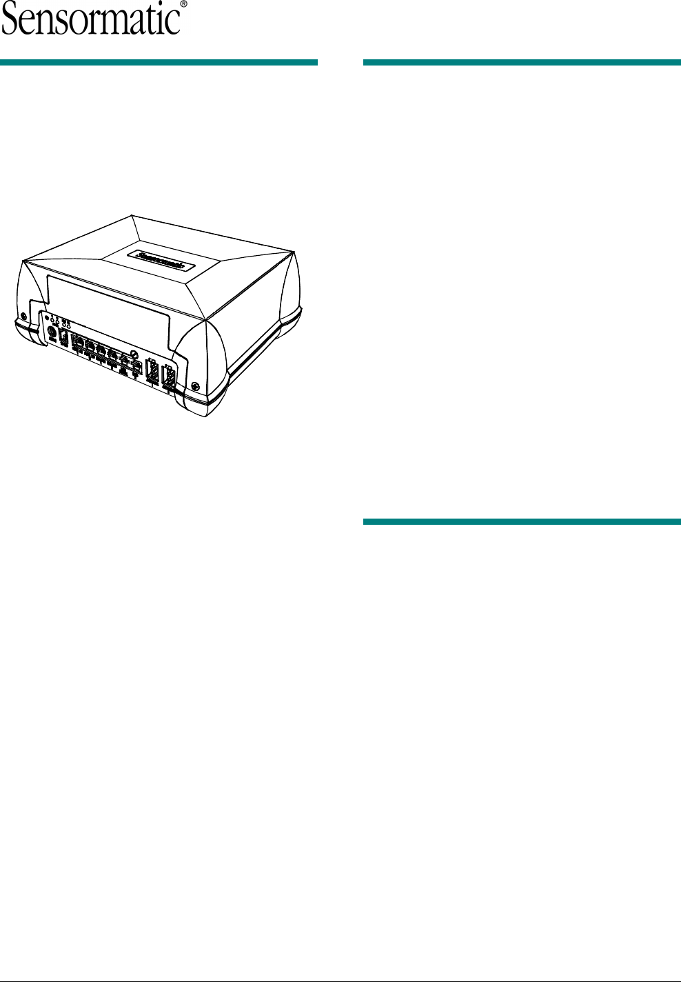
AMB-9020 Dual Antenna
ScanMax® Pro
Deactivator Controller
Installation and Service Guide
The Dual Antenna Deactivator controller, along
with an antenna, is used to deactivate security
labels. Antennas used with the controller are:
• PowerPad Pro (ZBSMPPP)
• Slim Pad Pro (ZBSMPSP)
• CompactPad Pro Tabletop (ZBSMPCP)
• CompactPad Pro Flush Mount (ZBSMPCP-F)
• HS Pro (ZBSMPHS)
• LP Pro (ZBSMPLP)
• IP Pro (ZBSMPIP)
• IS Pro (ZBSMPIS)
• NS Pro (ZBSMPNS)
• NS2 Pro (ZBSMPNS2)
IMPORTANT (all antennas)! If only one antenna
is used, it MUST be plugged into the Antenna 1
port or the unit will not function properly.
IMPORTANT (IS Pro only)! If two antennas are
used and one is an IS Pro antenna and one is not,
the IS Pro antenna MUST be plugged into the
Antenna 1 port or the unit will not function properly.
© Sensormatic 2003
Contents
About this Guide ....................................................1
About the Product ..................................................2
Product Overview ...............................................2
About the Controller............................................2
About the Antennas ............................................3
System Operation...............................................3
Indicators ............................................................3
POS Integration ..................................................4
Interconnection Cables.......................................4
Connector Inputs/Outputs......................................5
Installation..............................................................5
Basic Setup............................................................6
Controller Status Indicators ................................7
Remote Alarm Module........................................7
Advanced Setup and Adapter Configuration .........8
Troubleshooting .....................................................9
Basic Troubleshooting ........................................9
Advanced Troubleshooting...............................10
Specifications.......................................................12
Declarations .........................................................12
About this Guide
This guide explains how to install, setup, and
service the Dual Antenna Deactivator controller.
Other related documents are:
• Planning Guide, 8200-0365-03
• Software Configurator Guide, 8200-0365-04
Note: Because customer requirements dictate the
placement of components, your Sensormatic
representative will supply this information
separately.
If you need assistance...
Call 1-800-543-9740
(Sensormatic / ADT Customer Response Center)

Preliminary 2003-11-21
DUAL ANTENNA SCANMAX PRO DEACTIVATOR CONTROLLER 8200-0365-01, REV. 1A
INSTALLATION AND SERVICE GUIDE 2 of 12
About the Product
Product Overview
The Dual Antenna Deactivator controller supports
any two ScanMax Pro deactivation antennas used
to deactivate USII and USIII labels. A universal
input, 22Vdc output power supply powers the
controller.
The controller contains the necessary ports for:
• Wireless synchronization
• Network communication
• Maintaining independent antenna status
• Functional control for each antenna.
The controller also has:
• Automatic antenna type detection, except if
using the optional extension cable.
• Auto synchronization
• Automatic key switch detection
• Panel button for Label type (SR or DR) and
power level (Full or Magnetic Media Safe)
• LEDs that indicate power on, communication
activity, and diagnostics.
Product Limitations
• The controller has max duty cycle of three
times a second.
• Both antennas must have the same power
level and label type
• Max throughput speed of 203cm/sec
(80”/second) unless otherwise limited by the
antenna.
• Maximum distance between antenna and
controller is expected to be 3m (9.8ft), or 6m
(19.7ft) when optional extension cable 0652-
0136-01 is used.
• Antennas cannot deactivate simultaneously.
• No independent antenna power selection
(both antennas full or MMS)
• No independent antenna label selection
(both antennas same label setting)
• Low Profile Pad and PowerPad have a 10%
reduction in deactivation height.
Magnetic Media Safe Operation
Magnetic Media Safe (MMS) operation enables
security labels in audiotapes and videotapes to be
deactivated without affecting the media. MMS is
selectable using a software configurator, or using
the push button on the controller.
Synchronization
Auto-synchronization. Auto-synchronization
within the controller helps minimize tuning and
adjustment service calls. The controller
synchronizes to the antenna picking up the highest
in-band amplitude or to a wireless synchronization
input.
Wireless synchronization. The wireless
synchronization module plugs into the RS485 port
on the controller. If the TSP/Sensormatic network
is using this port, the module can be plugged into
the modular jack of the network terminal block
assembly.
About the Controller
The controller consists of an aluminum and plastic
enclosure that contains power and control
electronics. All connections are made to a
connector plate on one side of the unit.
Connections include:
• DC power in
• Two deactivation outputs
• Two remote indicator ports
• Two RS232 ports: POS 1 and POS 2 (the
service configurator uses only the POS 1 port)
• Two Scan I/O ports
• RS485 port.
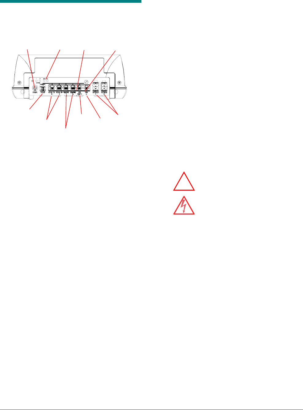
Connector Panel
Antenna 1
Antenna 2
Remote 1
Remote 2
LED for mag media safe (MMS)
LED for label type (SR)
Button: PROG
Control LED: Status 1 and Status 2
POS1/SERV
POS2
RS485
Scan IO 1
Scan IO 2

Preliminary 2003-11-21
DUAL ANTENNA SCANMAX PRO DEACTIVATOR CONTROLLER 8200-0365-01, REV. 1A
INSTALLATION AND SERVICE GUIDE 3 of 12
About the Antennas
The controller accepts any ScanMax Pro antenna.
These antennas automatically set the controller for
their antenna type and software settings when
plugged into the controller except when using an
extension cable. When using optional extension
cable 0652-0136-01 use the service configurator to
select antenna settings. EXTENSION IN USE must
be selected on the configurator as well.
System Operation
The Dual Antenna Deactivator generates an
alternating magnetic field that deactivates the label
by de-magnetizing the label’s bias material.
Deactivation Process
Deactivation is accomplished using electronics in
the controller and deactivation coils in the antenna
assembly. The Dual Antenna Deactivator uses a
resonance approach to generate the magnetic
fields needed for deactivation. A capacitor is
charged to a high voltage (on demand when a
deactivation needs to occur) and then switched in
parallel with the deactivation coil.
Detection Process
The detection process uses the same antenna
used for deactivation.
Digital Signal Processing (DSP) and frequency
sweeping enhance detection performance and
allow for hard tag discrimination.
Note: Hard tag discrimination depends on how
close the tag is to the deactivator. The further away
the tag is, the longer it takes the controller to
determine if a non-deactivateable tag is in the
deactivation zone.
Detection compensation is controlled by the
microprocessor allowing for adjustments to be
made for label type, antenna type, and operating
mode (Full Power or Magnetic Media Safe).
Control
The controller uses a microprocessor for
deactivation and detection control. The controller
also acts as the TSP/Sensormatic network hub
(described later in this document). The intent of the
RS485 network is to allow the POS register system
to communicate via RS232 (POS 1 or POS 2) to
other Sensormatic peripherals by allowing
commands to ‘pass through’ the controller to the
RS485 network.
The controller, when first powered up, can also
detect whether a key switch is in use. If detected,
the key switch setting is set as a default for the
system.
Diagnostic Capabilities
The Dual Antenna Deactivator provides power on
tests as well as continuous status of detection and
deactivation functions.
The LEDs on the controller display status to the
user. The controller displays a solid green light for
control good and red for a fault. The control LED
blinks green if the key switch is disabled.
Advanced diagnostics and analysis are available
through the deactivator software configurator. The
configurator features include zero crossing
adjustment, receive signal and noise levels,
operating mode selections, deactivation and
double check counts, and hours of operation.
Detection, scan enable, and deactivation outputs
are sent to the configurator. Settings for each
antenna can be adjusted independently (except
label type and power level) using their individual
set-up page.
Indicators
The controller has outputs that connect to the
standard remote alarm display, AcoustoLink, and
Footlink for each antenna. The controller provides
a visual power on/status indicator and indicators for
power mode and label type selection.
Control Power LED (Bi-color)
• Green: active
• Red: fault condition
• Blink Green 1/sec: deactivation disabled
• Momentary Amber: deactivation in progress
Programming button LEDs
• Yellow: reduced power for magnetic media
safe
• Yellow: single resonator low energy label
• MMS LED blinks to indicate EEPROM in
Antenna # 1 cannot be read
• SR LED blinks to indicate the EEPROM in
Antenna #2 cannot be read.
Note: SR label type and MMS selections apply to
both antennas

Preliminary 2003-11-21
DUAL ANTENNA SCANMAX PRO DEACTIVATOR CONTROLLER 8200-0365-01, REV. 1A
INSTALLATION AND SERVICE GUIDE 4 of 12
POS Integration
Scan I/O Port
POS integration uses the Scan I/O port and/or an
RS232 port. Scan I/O ports can be configured to
accept specific operating voltage levels to control
the deactivator. It will be compatible with the
AcoustoLink and Footlink options.
SCAN I/O Port Electrical Specifications
Maximum input voltage: +25Vdc ±5%
Input 1+ and Input 2+:
- Input voltage: 5–20Vdc positive or negative
polarity, >20–25Vdc positive polarity only
- Current: 10mA source minimum
- Minimum pulse duration: 100ms.
Detect Out: open-collector side of an opto-isolator
- Maximum pull-up voltage: +25Vdc
- This output remains in the open state until a
deactivation occurs. It then shorts to the Detect
Common for a minimum of 50ms based on label
vicinity to the antenna verse deactivation time.
Detect common: Emitter side of the Detect Out
opto-isolator normally should be tied to a ground
return. Maximum Current limit: 60mA.
Networking
The RS232 ports, if not used by a scanner
interface device or other auxiliary control device,
can be used for communicating to the customer
checkout register. The controller has a 6-position
modular jack (RJ11) that is the input/output for the
TSP/Sensormatic RS485 network. Information from
the register, when addressed correctly, passes
through the controller RS232 interface, to the
RS485 network, and on to its intended recipient.
To connect from the controller RS485 to
peripherals, such as an exit EAS system or tag
detacher, an optional interface assembly is
required. This assembly contains two 3 position
terminal blocks, two six-position modular jacks
(RJ11), and an input modular jack. The length of
the input cable from the controller to the networking
terminal block is determined by the baud rate and
line capacitance.
Interconnection Cables
The 183cm (6ft) power cord attaches to the
external power supply and into a 4-position mini-
din on the controller. The cord option selected
depends upon destination.
Cable length of SMPRO antennas is 3m (9.8ft).
The extension cable is 3m (9.8ft) long.

Preliminary 2003-11-21
DUAL ANTENNA SCANMAX PRO DEACTIVATOR CONTROLLER 8200-0365-01, REV. 1A
INSTALLATION AND SERVICE GUIDE 5 of 12
Connector Inputs/Outputs
RS485: RJ11 modular jack
Pin 1: GND
Pin 2: Line Sync OUT
Pin 3: Line Sync IN
Pin 4: RS485 HI
Pin 5: RS485 LO
Pin 6: +5
Scan I/O Port (2): RJ45 modular jack
Pin 1: +12Vdc
Pin 2: Input 1 +
Pin 3: Input 1 –
Pin 4: Input 2 +
Pin 5: Input 2 –
Pin 6: Out OC
Pin 7: Out Common
Pin 8: Ground
Serial Port (2): 4/4 Modular Jack
Note: Serial Port 1 (POS 1/SERV) is the only port
that can be used for the service configurator.
Pin 1: S1 Rx
Pin 2: S1 Tx
Pin 3: Ground
Pin 4: Not Connected
Remote Port (2): RJ11 Modular Jack
Pin 1: +22V
Pin 2: Red LED
Pin 3: Green LED
Pin 4: Audio
Pin 5: Key Switch
Pin 6: Ground
Antenna Out Port (2)
Pin 1: X
Pin 2: Y
Pin 3: X ret
Pin 4: Y ret
Pin 5: Shield
Pin 6: EEprom signal
Installation
The controller can be placed, out-of-the-box, on
the countertop. It can also be attached to the
underside of the countertop or to the sidewall of the
counter using a mounting bracket. This bracket
contains key slots for easy attachment.
WARNING! If mounting the controller to
the sidewall of a counter, its cable
connectors cannot face up.
Detailed mounting instructions are supplied with
the bracket (sold separately).
Equipment Required
• Controller
• Hard tag (non-deactivateable Ultra•Max tag)
• Ultra•Max deactivateable low energy labels.
Additional equipment required for advanced setup:
• Laptop with minimum Windows 95
• Standard CE RS232 Ultra•Max programming
cable
• Configurator software.
!
Preliminary 2003-11-21
DUAL ANTENNA SCANMAX PRO DEACTIVATOR CONTROLLER 8200-0365-01, REV. 1A
INSTALLATION AND SERVICE GUIDE 6 of 12
Basic Setup
Figure 1. Controller control panel
Note: This procedure is used for Antenna 1 and
Antenna 2. If only one antenna is used, it MUST be
plugged into the Antenna 1 port for the unit to
function properly.
Referring to Figure 1:
1. If used, plug either the indicator board cable
(PowerPad Pro antenna only) and/or the
remote alarm cable into the REMOTE port of
the controller. A Y-adapter is required if using
both devices.
2. Plug each antenna cable into one of the two
ANTENNA ports on the controller. If using only
one antenna, use only Antenna Port 1.
IMPORTANT! If two antennas are used and
one is an IS Pro antenna and one is not, the IS
Pro antenna MUST be plugged into the
Antenna 1 port or the unit will not function
properly.
Plug the dc power supply cord into the
controller. Do not plug the dc supply into the ac
outlet yet.
WARNING! Do not plug or unplug
ANY controller cables with power on.
WARNING—
RISK OF ELECTRIC SHOCK!
Keep the power cord and antenna
cable away from cash drawers and
other items whose operation may
pinch or otherwise damage them.
Failure to do so can damage
equipment or injure people nearby.
3. Plug the power supply into an ac outlet. The
status indicator may blink orange while the
controller auto-synchronizes. Once synchro-
nization is complete, this indicator should turn
solid green. Auto-synchronization can take up
to ten seconds.
Note: If the status indicator is blinking green,
either the deactivation or transmit function is
disabled. If the indicator is alternating
red/yellow or is solid red, then there is no high
voltage available for deactivation. For either
case, contact the Customer Response Center.
The complete list of status indications is shown
on page 7.
4. Verify operation by swiping a deactivateable
label across the antenna and passing it
through the EAS system at the exit.
!
Port 2
A
ntenna
Ports 1 and 2
Scan I/O Ports 1 and 2
Power Button
RS485 Ethernet
Mode Indicators
Service
Port 1
POS Port
Remote Ports 1 and 2
Preliminary 2003-11-21
DUAL ANTENNA SCANMAX PRO DEACTIVATOR CONTROLLER 8200-0365-01, REV. 1A
INSTALLATION AND SERVICE GUIDE 7 of 12
Controller Status Indicators
Status Indicator on Controller (Note: Orange
lamp may appear yellow.)
Solid Green Unit ready.
Blinking Green Transmit disabled in detect
only mode or by key switch
or configurator.
Blinking Orange Controller is in auto-sync.
Solid Red Non-recoverable fault.
Mode Indicator on Controller (Press the panel
button to cycle through the selections below.)
SR LED on The controller is set for use
with an SR label.
SR LED off The controller is set for use
with a DR label.
MMS LED on The controller is set for
Mag-Safe operation.
MMS LED off The controller is set for
routine operation.
MMS LEDs blinks Antenna 1 EEPROM fault.
SR LED blinks Antenna 2 EEPROM fault.
Status Indicators on
Remote Alarm Module (if used)
Green On, Red Off Unit ready.
Blinking green Transmit disabled in
detect only mode or by
key switch or
configurator.
Blinking green and red
(For PowerPad Pro,
blinking orange)
Controller is in auto-sync.
Green on, Red flashing
every 250ms
The high voltage circuit is
not working.
One beep The controller attempted
to deactivate a label.
Slow beep until a hard tag
is removed from the field.
The controller is in HT
Test Mode.
Multiple Fast Beeps Label present in
Doublecheck or Detect
Mode.
Solid Red Label present in Detect
Mode.
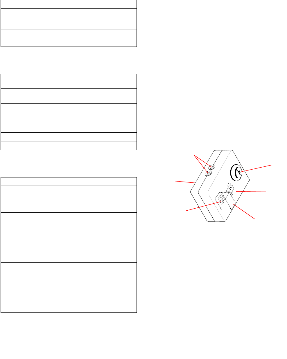
Remote Alarm Module
The remote alarm module (Figure 2) plugs into the
REMOTE port on the controller. It contains the
following:
a. Deactivation inhibit keyswitch. The key is
turned 90° to inhibit deactivation.
b. LEDs. Red and green LEDs indicate routine
operation, special modes, and system faults.
c. Beeper. Provides audio indication of detection.
d. High/Low volume control slide switch.
e. Phone jack. Receives a 2.1m (7ft) modular
cable from the REMOTE port on the controller.
f. Two keyhole slots (not shown). Two slots in
the back of the module attach it to a suitable
mounting surface. Two screws secure the unit.
Note: You may need the remote alarm module to
diagnose certain problems with the deactivator.
Figure 2. Remote alarm module
b
f
c
e
d
a

Preliminary 2003-11-21
DUAL ANTENNA SCANMAX PRO DEACTIVATOR CONTROLLER 8200-0365-01, REV. 1A
INSTALLATION AND SERVICE GUIDE 8 of 12
Advanced Setup and
Adapter Configuration
Note: Be sure to adjust the correct antenna
settings as indicated on the title bar of the
configurator screen.
Note: If the antenna has optional extension cable
PN XXXX, you MUST select Extension Cable in
the Antenna Setup for the unit to function properly.
1. Plug your laptop programming cable into the
POS 1/SERV port of the controller.
2. Click the desktop icon to start the configurator
software. The Setup Screen appears. For
control definitions, see the Software
Configurator Guide.
3. Verify settings correspond to the antennas
used as follows. Do not change settings yet.
Default Settings
Antenna Tx Power Threshold
LP Pro Pad Med 8 (+1) inches
20 (+2.5) cm
PowerPad
Pro
Med 7 (+1.5) inches
17.5 (+3.75) cm
SlimPad Pro Med 6 (+1.5) inches
15 (+3.75) cm
IP Pro Med 6 (+1.5) inches
15 (+3.75) cm
CompactPad
Pro
Med 6 (+1) inches
15 (+2.5) cm
ScanMax IS* Med 5 (+1) inches
12.7 (+2.5) cm
ScanMax HS Med 5 (+1) inches
12.7 (+2.5) cm
ScanMax NS Med 5 (+1) inches
12.7 (+2.5) cm
4. Use the Detection Height setting to adjust the
detection height for the checkout environment
and to compensate for special mounting such
as metal countertops.
5. Click the EXIT button on the configurator to
exit the configurator.
* ScanMax IS Enhanced Detection Mode Option. To
enable 16.5–17.8cm (6.5–7in) detection with 10.2–
12.7cm (4–5in) deactivation, set detection
compensation on the diagnostics screen to +20 for X
and Y.
If only “one” ScanMax IS antenna is used it MUST be
plugged into the Antenna 1 port or the unit will not
function properly.
If unexplained deactivation occurs…
Follow this procedure (except step 3) for each
antenna as autosync should be completed only
once. Manual operation must be used thereafter,
as autosync will take both antennas out of their
previous sync delay settings.
If false deactivation occurs, the configuration
default values need to be modified as follows:
1. Plug your laptop programming cable into the
POS 1/SERV port of the controller.
2. Start the AMB-9020 software configurator by
clicking on the desktop icon. The Setup Screen
appears (see Software Configurator Guide).
3. On the Setup screen, click the RESYNC
button. Verify auto sync is enabled. If
unexplained deactivation discontinues,
readjust the Detection Height setting;
otherwise, continue.
4. Ensuring no label/tag is close to the antenna,
reduce the Detection Height setting one level
at a time until the system does not false
deactivate (firing without a label/tag present).
Write this level down.
5. Set Detection Height level one step higher.
Note: Maximum detection and deactivation
height may be reduced compared with that
listed in the table due to ambient noise and
mounting locations. Note the new height.
6. If these steps fail to stop false deactivation, call
the Customer Response Center for service.

Preliminary 2003-11-21
DUAL ANTENNA SCANMAX PRO DEACTIVATOR CONTROLLER 8200-0365-01, REV. 1A
INSTALLATION AND SERVICE GUIDE 9 of 12
Troubleshooting
Basic Troubleshooting
If the deactivator is not deactivating
labels…
1. Ensure all cables are plugged into the
controller. Do not hot plug the antenna cable or
the power cable from the controller.
2. Is the green LED on the controller lit?
• If not, there is no ac power and the unit
cannot operate. Ensure the power supply
is plugged into the ac outlet. If it is, check
your store breaker panel.
• If it is, go to next step.
3. With no EAS label on the antenna check the
color of the status indicator on the controller.
• Green—go to next step.
• Blinking green—transmitter is disabled or
the unit is in Detect Only Mode. This
occurs if the unit was configured with an
optional remote and/or key switch and that
remote was removed or damaged. To
enable deactivation, turn the key switch of
the remote unit to the on position and the
light should turn solid green. This also
bypasses any scan-enable function. If not
in Detect Only Mode and no optional
remote is connected, place a service call.
• Yellow or red is solid or blinking—call the
Customer Response Center to place a
service call.
Note: It is possible that a hard tag (non-
deactivateable label such as that placed on
clothing) is within the deactivation area.
• If a remote is present: A slow ‘beep’
indicates this as an issue and the tag must
be found and removed from the
deactivation area.
• If the remote is not present: Turn the unit
on and off using the green rocker switch. If
the green status LED comes on and there
is an immediate 2 to 3 deactivations and
then deactivation no longer continues,
there is a non-deactivateable label present
that must be removed from the
deactivation area.
If the system indicates the presence of a non-
deactivateable label, but none is found, call the
Customer Response Center for service.
If the deactivator continuously
deactivates…
This indicates interference from nearby POS
equipment picked up by the deactivation antenna.
Try to reposition equipment such as check readers
or displays. If deactivation continues, a service call
is necessary.
If deactivation height is significantly less
than it should be…
Is the MMS LED mode indicator solid yellow?
If yes, this indicates low power deactivation,
typically 7.6cm (3in), but dependent on antenna
type. If low power deactivation is not a
requirement, press the PROG button until both
MODE LEDs go out.
The deactivator automatically adjusts its detection
and deactivation areas continuously based on the
noise environment. Typical operation should be at
about 2.5cm (1in) less than what it would be if the
Threshold were set manually. If operation is
outside this tolerance, do the following:
1. Be sure a label is not within the deactivation
area.
2. Turn power off and on by unplugging and then
replugging the ac line cord in the ac outlet.
3. Once the status light turns green, wait five
seconds and check the deactivation/detection
height.
4. If performance remains poor, call the Customer
Response Center to place a service call.
Certain types of counter installations may cause
the deactivation height to be less than the height
indicated by the configurator. In rare instances, the
counter type may even cause deactivation
attempts at a height outside the height specified.
To ensure the deactivator operates within the
indicated height, use Detection Compensation. See
“If Deactivation Height is Low” and “If the
Deactivator Fires at a Label Outside the Dx Area”.

Preliminary 2003-11-21
DUAL ANTENNA SCANMAX PRO DEACTIVATOR CONTROLLER 8200-0365-01, REV. 1A
INSTALLATION AND SERVICE GUIDE 10 of 12
Advanced Troubleshooting
Use this procedure only when the following occurs:
• Unit is not deactivating labels
• Unit false fires
• Deactivation height is very low
Equipment required: EAS non-deactivateable
label, laptop with minimum Window 98 SE, service
configurator, RS232 programming cable (standard
Ultra•Max CE cable).
Before You Begin…
Be sure you have completed basic troubleshooting
before using this procedure. If troubleshooting is
still necessary, turn on the controller and connect
the RS232 cable to your serial port and the POS
1/SERV port of the controller.
Note: As indicated in basic troubleshooting, a solid
red light on the status indicator is non-repairable at
the customer site. Return the unit to the service
center for repair.
Note: If swapping out the controller for a new one,
no set-up is required. Simply plug in all cables and
turn the unit on. Inform the customer that the unit is
“advance replaceable” and that a service call is not
necessary.
If the Unit does not Deactivate…
If basic troubleshooting has been completed and
the green LED is still blinking:
1. See if a non-deactivateable label (hard tag) is
within 30.5cm (12 in) of the antenna.
2. On the set-up screen for the antenna being
tested, disable Hard Tag Check and ensure
Detect Only is not enabled.
3. Unplug the DC power supply from the ac outlet
and then plug it back in. If deactivation occurs,
there is a non-deactivateable label or hard tag
within the deactivation area preventing normal
operation. Remove the label or hard tag.
Note: If the label causing the problem cannot
be found, swap the controller with one from an
adjacent register. If the problem continues,
something within the checkout area responds
to the detection field like a label and the Hard
Tag Check mode must remain disabled for
operation. If the unit still does not deactivate,
return it for service.
If the Unit False Fires…
1. Re-sync the controller by pressing the Re-Sync
button on the configurator. Be sure
AUTOSYNC is enabled. If false firing
stops, troubleshooting is complete.
2. Remove the antenna and rotate it horizontally
and vertically until deactivation stops. Rotate
the antenna again until deactivation begins.
This is the direction of interference.
3. Reposition equipment that may be causing
interference such as card readers and
displays. Typically, most POS equipment
should be 30.5cm (12in) from the antenna.
4. If false firing stops, troubleshooting is
complete. If false firing continues, do the
following:
On the setup screen make sure that
Detection Compensation is set to 0. If false
firing continues, go to the next bullet.
On the diagnostics screen of the
configurator, look at the noise levels. If
possible, rotate the antenna until the noise
is minimized.
Adjust the threshold level on the
configurator down one-step-at-a-time until
false deactivation stops. Set the threshold
one step higher. Troubleshooting is
complete. If false deactivation
continues go to next step.
If the Deactivator Fires at a Label
Outside the Dx Area…
It is possible that the metal counter or mounting
bracket is affecting the detection field.
On the configurator, while holding a tag above the
center of pad, adjust Detection Compensation
negative until firing occurs only when tag is at or
below the deactivation height set on the
configurator.
On the configurator adjust the Detection
Compensation negative. If false deactivation stops
and the deactivation height is OK, troubleshooting
is complete. If not, return the controller for service.

Preliminary 2003-11-21
DUAL ANTENNA SCANMAX PRO DEACTIVATOR CONTROLLER 8200-0365-01, REV. 1A
INSTALLATION AND SERVICE GUIDE 11 of 12
If Deactivation Height is Low…
1. Observe the noise level indicator on the
configurator.
2. With customer approval, reposition POS
equipment such as card readers and displays
until the noise level minimizes. Typically, most
POS equipment should be 30.5cm (12in) from
the antenna.
If deactivation performance is acceptable,
troubleshooting is complete. If the noise level
does not decrease to where deactivation is
acceptable, continue to the next step.
3. INCREASE transmitter power to maximum. If
false deactivation does not occur, this setting
can be used. If deactivation height has not
improved, continue to next step.
4. Is it possible that a metal counter or mounting
bracket affected the detection field?
On the configurator, while holding a label
above the center of the pad, adjust Detection
Compensation positive until firing occurs only
when tag is at and below the deactivation
height set on configurator.
Note: Depending on the severity,
compensation may not be enough to restore
operation to maximum deactivation height.
On the configurator, adjust Detection
Compensation positive. If deactivation height
improves, troubleshooting is complete. If not,
return the controller for service and contact
Sensormatic Technical Support via the
Customer Response Center.

Preliminary 2003-11-21
DUAL ANTENNA SCANMAX PRO DEACTIVATOR CONTROLLER 8200-0365-01, REV. 1A
INSTALLATION AND SERVICE GUIDE 12 of 12
Specifications
The input voltage to the power supply shall be 90–
264 VAC, 50 or 60 Hz ±5%. AC line current shall
not exceed 2 amps rms. The power supply output
to the controller must be 22Vdc +5%. Sensormatic
power supply 606-0049-01 is specified for this
application.
Electrical
Voltage input
to power supply ........................... 90–264Vac,
50/60Hz (±5%)
Voltage input
from power supply ....................... 22Vdc
AC line current............................. 2Arms
Environmental
Operating temperature................. 0 to 40°C
(32° to 104°F)
Non-operating temperature.......... –40° to 70°C
(–40° to 158°F)
Relative humidity ......................... 0 to 90%
non-condensing
Mechanical
Height .......................................... 10cm (3.9in)
Width ........................................... 26.3cm (10.4in)
Depth ........................................... 22.1cm (8.7in)
Weight ......................................... 2.5kg (5.5 lbs)
Declarations
Regulatory Compliance
EMC ...............................................47 CFR, Part 15
RSS 210
EN 300 330
EN 301 489
Safety....................................................... UL 60950
CSA C22.2 No 60950
EN 60950
FCC COMPLIANCE: This equipment complies with Part 15
of the FCC rules for intentional radiators and Class A digital
devices when installed and used in accordance with the
instruction manual. Following these rules provides reasonable
protection against harmful interference from equipment
operated in a commercial area. This equipment should not be
installed in a residential area as it can radiate radio frequency
energy that could interfere with radio communications, a
situation the user would have to fix at their own expense.
EQUIPMENT MODIFICATION CAUTION: Equipment
changes or modifications not expressly approved by
Sensormatic Electronics Corporation, the party responsible for
FCC compliance, could void the user's authority to operate the
equipment and could create a hazardous condition.
Other Declarations
WARRANTY DISCLAIMER: Sensormatic Electronics
Corporation makes no representation or warranty with respect
to the contents hereof and specifically disclaims any implied
warranties of merchantability or fitness for any particular
purpose. Further, Sensormatic Electronics Corporation
reserves the right to revise this publication and make changes
from time to time in the content hereof without obligation of
Sensormatic Electronics Corporation to notify any person of
such revision or changes.
LIMITED RIGHTS NOTICE: For units of the Department
of Defense, all documentation and manuals were developed at
private expense and no part of it was developed using
Government Funds. The restrictions governing the use and
disclosure of technical data marked with this legend are set
forth in the definition of “limited rights” in paragraph (a) (15)
of the clause of DFARS 252.227.7013. Unpublished - rights
reserved under the Copyright Laws of the United States.
TRADEMARK NOTICE: ScanMax and Sensormatic are
registered trademarks of Sensormatic Electronics Corporation.
Other product names mentioned herein may be trademarks or
registered trademarks of Sensormatic or other companies.
No part of this guide may be reproduced in any form without
written permission from Sensormatic Electronics Corporation.
MDR 11/03