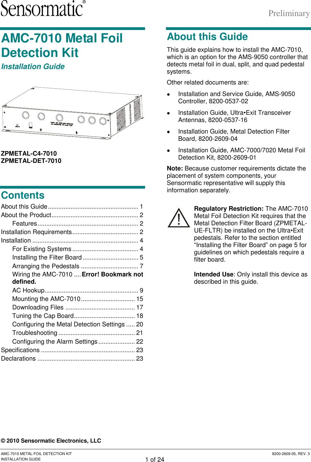
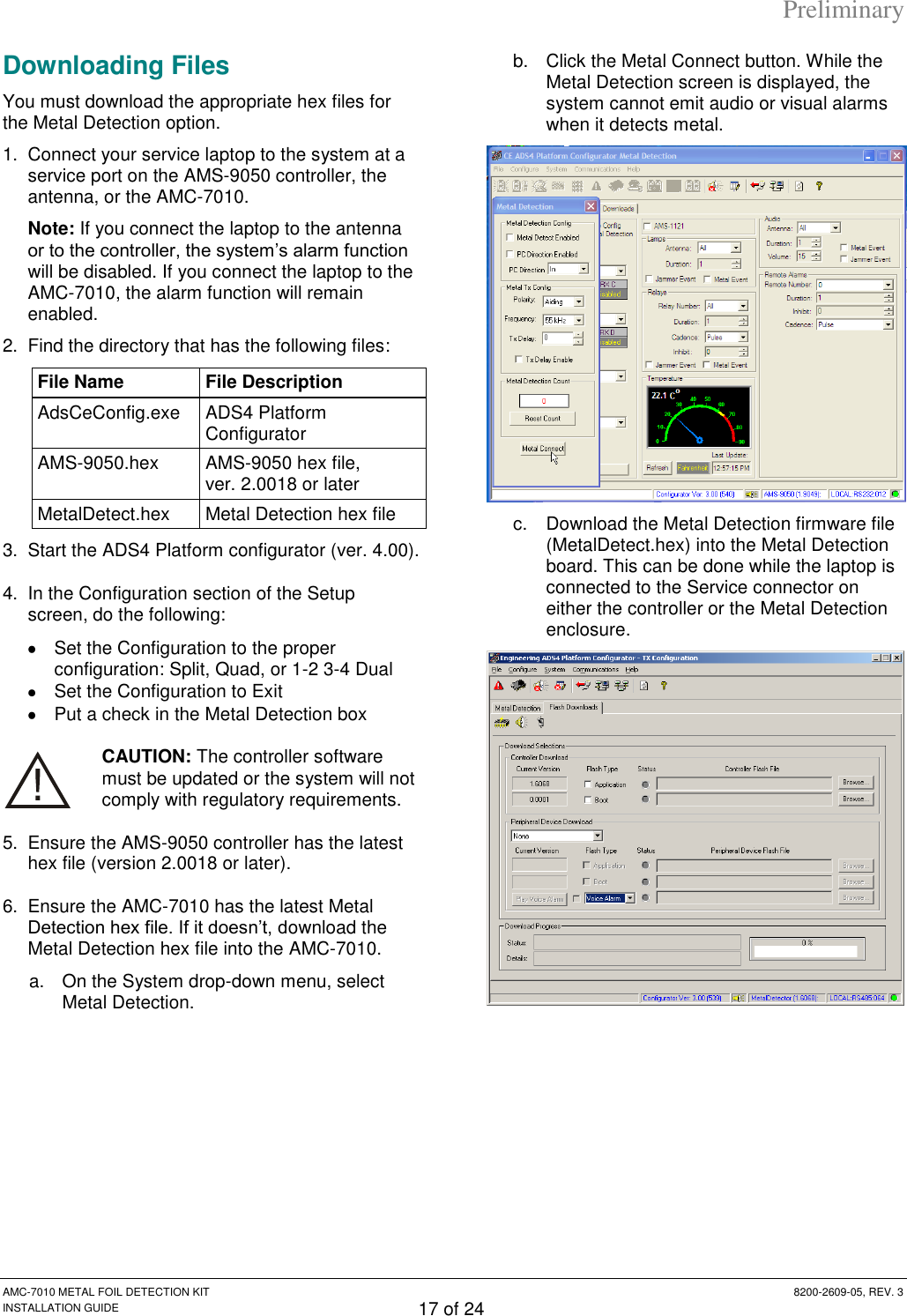
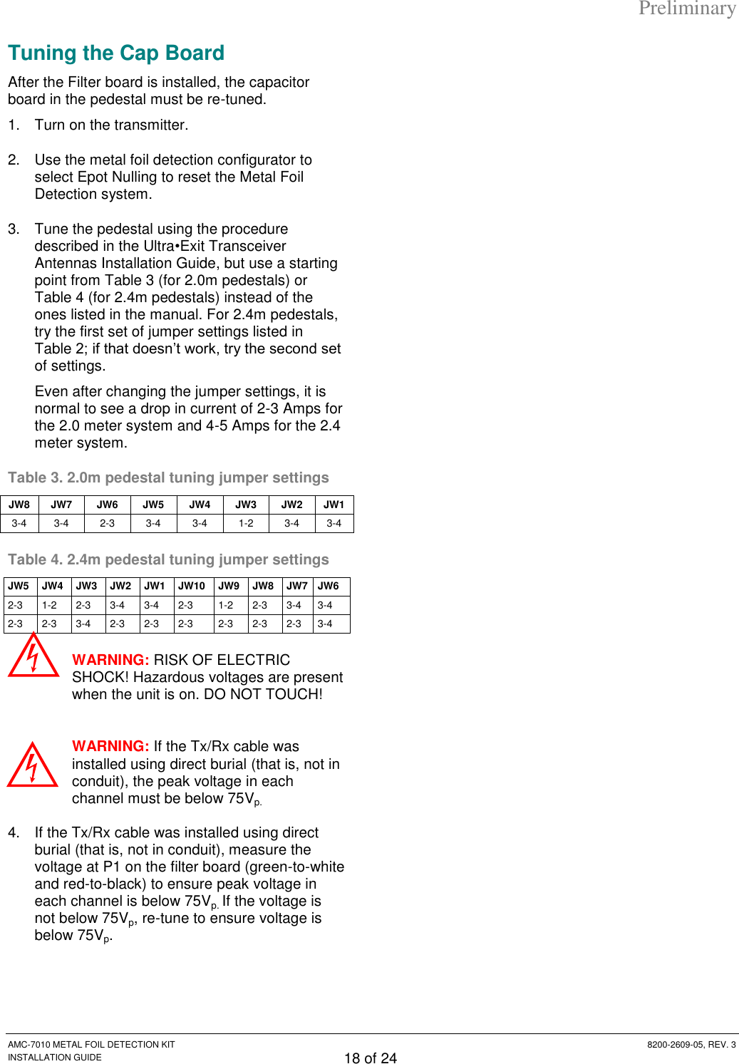
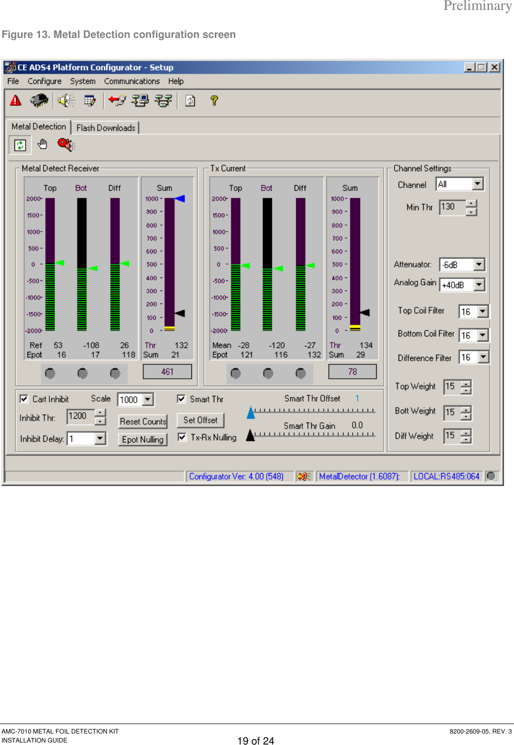
Tyco Safety Sensormatic AMC7010 Anti-Pilferage Device User Manual users manual

Tyco Safety Products/Sensormatic Anti-Pilferage Device users manual

users manual

Preliminary AMC-7010 METAL FOIL DETECTION KIT  8200-2609-05, REV. 3 INSTALLATION GUIDE 1 of 24 AMC-7010 Metal Foil Detection Kit Installation Guide  ZPMETAL-C4-7010 ZPMETAL-DET-7010 Contents About this Guide .................................................... 1 About the Product .................................................. 2 Features .......................................................... 2 Installation Requirements ...................................... 2 Installation ............................................................. 4 For Existing Systems ...................................... 4 Installing the Filter Board ................................ 5 Arranging the Pedestals ................................. 7 Wiring the AMC-7010 .... Error! Bookmark not defined. AC Hookup ...................................................... 9 Mounting the AMC-7010 ............................... 15 Downloading Files ........................................ 17 Tuning the Cap Board ................................... 18 Configuring the Metal Detection Settings ..... 20 Troubleshooting ............................................ 21 Configuring the Alarm Settings ..................... 22 Specifications ...................................................... 23 Declarations ........................................................ 23 About this Guide This guide explains how to install the AMC-7010, which is an option for the AMS-9050 controller that detects metal foil in dual, split, and quad pedestal systems.  Other related documents are:   Installation and Service Guide, AMS-9050 Controller, 8200-0537-02   Installation Guide, Ultra•Exit Transceiver Antennas, 8200-0537-16   Installation Guide, Metal Detection Filter Board, 8200-2609-04   Installation Guide, AMC-7000/7020 Metal Foil Detection Kit, 8200-2609-01 Note: Because customer requirements dictate the placement of system components, your Sensormatic representative will supply this information separately. Regulatory Restriction: The AMC-7010 Metal Foil Detection Kit requires that the Metal Detection Filter Board (ZPMETAL-UE-FLTR) be installed on the Ultra•Exit pedestals. Refer to the section entitled “Installing the Filter Board” on page 5 for guidelines on which pedestals require a filter board. Intended Use: Only install this device as described in this guide. © 2010 Sensormatic Electronics, LLC
Preliminary AMC-7010 METAL FOIL DETECTION KIT  8200-2609-05, REV. 3 INSTALLATION GUIDE 2 of 24 About the Product The AMC-7010 Metal Foil Detection kit (ZPMETAL-DET-7010) covers split pedestal configurations. It also covers quad pedestal configurations with the addition of the ZPMETAL-DET-C4 kit. This AMS-9050 accessory detects metal having a large surface area, such as aluminum foil, when it passes between the pedestals of a system. It is designed to not detect metal objects with small continuous surfaces, such as keys and shopping carts. The kit can only be used with AMS-9050 controllers.  The AMC-7010 is an accessory for AMS-9050 controllers connected to 2m Ultra•Exit pedestals (ZS1090, ZS1091, ZS1092and ZS1102) or 2.4m Ultra•Exit pedestals (ZS1130, ZS1131, ZS1121, and ZS1132) with the Integrated Traffic Flow option (ZPUE-TRAFFICNTR). Although the AMC-7010 can handle dual, split, or quad pedestal configurations, the AMC-7000 and AMC-7020 options are usually used for dual configurations.  Features   Automatic Detection Adjustment – the system adjusts itself to changes in the amount of metal in the environment.   Enclosure is suitable for use in environmental air handling space other than ducts or plenums.   Directional Inhibit support – using the People Counter option, system can be set to alarm for incoming metal only, out-going metal only, or both.   Multiple alarm methods – the system can indicate the presence of metal foil by several methods: a visual alarm at the pedestal, an audio alarm at the pedestal, the triggering of a relay that connects to another device (such as a paging system), or an alarm at a digital remote alarm.   Metal foil detection counts – the number of metal foil detections can be displayed on an optional Local Device Manager (LDM).   Large coverage area – detects metal between two antennas up to 1.5m (5ft) off the floor between the two pedestals.   Wired synchronization – synchronization of the controller with other controllers must be done with Universal Synchronization instead of wired synch because the Wired Synch port is needed for Metal Foil Detection. Installation Requirements Verifying Equipment and Unpacking   Verify that all equipment has arrived. Ensure the system configuration is correct for the site.   Unpack major components in a back room. At the install site, lay out parts in the order used. Do not clutter the aisle or cause a trip hazard. Installer/Contractor   Have electrical work comply with the latest national electrical code, national fire code, and all applicable local codes and ordinances.   Coordinate work with other trades to avoid interference.   Verify existing site conditions and coordinate with the owner’s representative and appropriate utilities as required.   Obtain copies of all related plans, specifications, shop drawings and addenda to schedule and coordinate related work.   Thoroughly review the project to ensure that all work meets or exceeds the above requirements. Bring alleged discrepancies to the attention of Sensormatic Electronics. Mounting Requirements   The AMC-7010 has a built-in flange used to attach the enclosure to a wall or ceiling using suitable hardware. Structure and hardware must support 25.6kg (56.4 lb) or four times the weight of the enclosure assembly.   Do not mount enclosure with its fan facing up. Pedestal Placement   Minimum distance between two Ultra*Exit pedestals is 1.2m (4.0ft) measured center-to-center.    If there is another Metal Detection system in the area and the two closest pedestals of the system are within 11m (35ft) of each other, you must sync the AMS-9050 controllers with a Wired Sync option.
Preliminary AMC-7010 METAL FOIL DETECTION KIT  8200-2609-05, REV. 3 INSTALLATION GUIDE 3 of 24 AC Requirements WARNING—RISK OF ELECTRIC SHOCK! During installation, if the antenna must be left unattended, turn off power or cover high voltage components to prevent unauthorized access to hazardous voltages. WARNING—RISK OF ELECTRIC SHOCK! The ac power cord could be carrying 120Vac or 240Vac. WARNING! Do not install this device where highly combustible or explosive products are stored or used. WARNING! The AC source must be a 2-wire type with ground. It also must be a 24-hour, unswitched outlet with less than 0.5Vac between neutral and ground. WARNING! This device is not suitable for an IT power distribution system where impedance exists between neutral and protective earth contacts. CAUTION: When using a power cord, install a socket-outlet near the AMC-7010 in an easily accessible location. The appliance coupler or plug on the power supply cord are the specified disconnect devices. CAUTION: DO NOT share the AC source with neon signs, motors, computers, cash registers, terminals, or data communications equipment. CAUTION: DO NOT use orange-colored outlets dedicated for computer equipment. CAUTION: Select the appropriate power cord based on the country of use. Mounting the Controller WARNING! Do not mount the AMC-7010 with its fan face up. The AMC-7010 can be mounted as follows:   On a wall.   To a ceiling. Plywood with a surface larger than the controller is secured to the ceiling studs that hold the drywall. The controller then attaches with suitable hardware to the plywood. Equipment Required Basic setup requires the following equipment:   AMS-9050 controller   Pedestal antennas   Hard tag (non-deactivateable Ultra•Max® tag)  Ultra•Max low energy labels. Advanced setup requires the following additional equipment:   Laptop with Windows® 95, 98, NT, 2000, or XP operating system software  RS-232 Ultra•Max programming cable   ADS 4 service configurator software. Implanted Medical Devices Although this anti-theft system complies with all applicable safety standards, place the system in such a way that customers:   do not linger near or lean on its antenna(s)   are only directly in front of the antenna(s) while exiting the store or facility.  Do not cover the “Anti-Theft System” label on antennas. If the country’s language is different from English, apply “Anti-Theft” labels in the local language to the antennas. Labels in your local language (2412-0170-XX) can be ordered from your distribution center. !!!!
Preliminary AMC-7010 METAL FOIL DETECTION KIT  8200-2609-05, REV. 3 INSTALLATION GUIDE 4 of 24 Installation The ZPMETAL-DET-7010 kit consists of the parts necessary to install Metal Foil Detection on a three-pedestal (split) system: Part Qty. Part Number Split/quad metal detection controller 1 0319-0019-01 Cable clamps 6 6010-0036-01 Metal foil filter board 3 0304-3081-01 Splash guard 3 0505-1436-01 Screws, M3x10, PHP 12 5801-1061-120 Wired sync cable 1 0652-0467-01 Tx/Rx cable 4 0652-0467-02 Power supply/RS-485 cable 1 0652-0468-01 Connector assy, Aux/WS (5-pin) 1 0304-2887-01 Connector assy, RS-485  1 0304-2885-01 Vinyl cloth marker #1 1 6009-0057-01 Vinyl cloth marker #2 1 6009-0057-02 Vinyl cloth marker #3 1 6009-0057-03 Vinyl cloth marker #4 1 6009-0057-04 Vinyl cloth marker #5 1 6009-0057-05 Vinyl cloth marker #6 1 6009-0057-06  For quad-pedestal systems, you must use the ZPMETAL-C4-7010 configuration. It consists of the ZPMETAL-DET-7010 kit plus an additional kit (ZPMETAL-UE-FLTR) that has the equipment required for a quad (four-antenna) system. The ZPMETAL-UE-FLTR kit contents are listed below. Part Qty. Part Number Metal foil filter board 1 0304-3081-01 Splash guard 1 0505-1436-01 Screws, M3x10, PHP 4 5801-1061-120 For Existing Systems If you are installing an AMC-7010 on an Ultra•Exit system that is already installed and working, do the following before turning off the system and starting the installation process. 1.  Perform a tag-pick test so that you can compare system performance afterwards. 2.  Save the system settings to a file. CAUTION: The controller software must be updated or the system will not comply with regulatory requirements. 3.  Download the latest version of the controller software to the AMS-9050 controller.  4.  Use the vinyl cloth markers to label the cables coming out of the AMS-9050. The following figures show how the cables should be labeled. The labels are shown next to the connector they should be applied to. Note that the labeling is different depending on whether the existing system is configured as a split system, an alternating split system, or quad system. CAUTION: You must label the cables correctly and connect them to their proper connectors or the system will not operate properly. Figure 1. Labeling split system cables  Figure 2. Labeling alternating split system cables  Wired Sync Remote Alarm Ant B Tx Ant C Tx Ant A Alarms Ant B Alarms Ant C Alarms Ant A Tx 3 4 2 3 4 2 5 6 A AMS-9050 C B Wired Sync Remote Alarm Ant B Tx Ant C Tx Ant A Alarms Ant B Alarms Ant C Alarms Ant A Tx 3 2 4 3 2 4 5 6 A AMS-9050 B C
Preliminary AMC-7010 METAL FOIL DETECTION KIT  8200-2609-05, REV. 3 INSTALLATION GUIDE 5 of 24 Figure 3. Labeling quad system cables  Installing the Filter Board For dual systems, you must install the Metal Detection Filter Board kit (ZPMETAL-UE-FLTR) on the Ultra•Exit pedestal that transmits during the metal detection phase (pedestal C). For split and quad systems, you must install a Filter board in each pedestal. You install the Filter board in the same location as the People-counting (Traffic Flow) board. 1.  Remove the base cover from one of the pedestals. 2.  For dual systems, identify which pedestal is the metal foil detection transmitter (pedestal “C”).  a)  Connect the configurator cable from the laptop to the RS232 port at one of the pedestals and start the configurator. b)  Hold the EAS tag or label behind or next to each pedestal and observe the tag signal strength each time to determine which pedestal is the “C” pedestal. c) Note the transmitter current on the “C” pedestal. WARNING: RISK OF ELECTRIC SHOCK! Ensure the transmitter is off before proceeding with the next step. 3.  Turn off the transmitter and unplug the Tx/Rx cable from the cap board of the pedestal.  4.  Does the pedestal have a People-counting (Traffic Flow) board installed in the base?  No. Using the four M3x10mm screws provided, attach the Filter board to the four standoffs below the capacitor board. See Figure 4 or Figure 5.  Yes. You need to clear space for the Filter board. The procedure depends on whether this is a dual, split or quad pedestal system. – If this is a split or quad pedestal system, move the people counting board to the back side of the pedestal.   If the pedestal is a non-acrylic model (ZS1090, ZS1091, ZS1092, ZS1130, ZS1131, ZS1132, ZS1133-PIEZO) and it uses a ZPUE-SSBASE1, ZPUE-SSBASE2, or ZPUE-SSBASE3 base cover, mount the people counting board directly to the back side of the pedestal.   If the pedestal is an acrylic model (ZS1100, ZS1101, ZS1102, ZS1121 ZS1122) or it uses any antenna with a ZPUE-SSBASE4 base cover, you will need the People Counting Bracket kit ZPMETAL-PC-BRKT. See the installation guide included with the bracket for installation instructions. – If this is a dual pedestal system, you need to do one of the following steps.    Move the people-counting board to the other pedestal and swap the Transmitter and Receiver sensors under the alarm lens.  P1 Transceiver cable Wired Sync Remote Alarm Ant B Tx Ant C Tx Ant D Tx Ant A Alarms Ant B Alarms Ant C Alarms Ant D Alarms Ant A Tx 1 2 3 4 1 2 3 4 5 6 A C B D AMS-9050
Preliminary AMC-7010 METAL FOIL DETECTION KIT  8200-2609-05, REV. 3 INSTALLATION GUIDE 6 of 24  Swap the “A” and “C” connections for the Tx/Rx cables and Alarm cables back at the AMS-9050 controller.  Once you have cleared the space for the Filter board, use the four M3x10mm screws provided to attach the Filter board to the four standoffs below the capacitor board. See Figure 4 or Figure 5. Figure 4. Location of standoffs in plastic base  Figure 5. Location of standoffs in acrylic base  5.  Connect one end of the cable on the Filter board to connector P1 on the cap board. To prevent stress on the connector, you should bend the wires back before connecting, as shown below.  6.  Connect the Tx/Rx cable to the P1 connector on the Filter board.  7.  Loosen the mounting bolts holding the base to the floor. 8.  Insert the slotted area of the splash guard underneath the pedestal base. Transceiver cable P1 Standoffs Standoffs
Preliminary AMC-7010 METAL FOIL DETECTION KIT  8200-2609-05, REV. 3 INSTALLATION GUIDE 7 of 24  9.  Tighten the mounting bolts. 10. Reattach the base cover to the pedestal. Arranging the Pedestals To ensure proper operation of the system, the pedestals must be arranged in a specific layout. The required layouts for dual, split, and quad systems are shown in Figure 6. Note the following:    The pedestals must be oriented with the sides containing the cap board as shown in Figure 6. CAUTION: Do NOT use the “C” pedestal as the middle pedestal with split pedestal systems or the system will not work properly.   Split systems must be wired with the B pedestal as the middle pedestal.   Quad systems may be used to cover one large exit or two separate exits.  All pedestals except the “A” pedestal in a dual configuration must have a Filter board installed. WARNING—RISK OF ELECTRIC SHOCK! Do not wire with power applied. Figure 6. Pedestal layout for Metal Foil Detection systems    A C* Dual Pedestals C* B* D* Split Pedestals A* C* B* D* Quad Pedestals Splash guard A* C* B* D* Dual 1-2 3-4 Pedestals *  Pedestals marked with an asterisk require a filter board Note: Middle pedestal is ―B‖ in split systems. Black rectangle represents side of pedestal with cap board.
Preliminary AMC-7010 METAL FOIL DETECTION KIT  8200-2609-05, REV. 3 INSTALLATION GUIDE 8 of 24 Cabling an Existing AMS-9050 System Follow this procedure to connect the cables to an existing AMS-9050 system (that is, one that is already installed and functioning as an anti-theft system). Observe the following rules:   Use the supplied cable clamps when connecting the cables to the AMC-7010 enclosure. Do not substitute with other cable hardware.   Route the cables through the knockout closest to their connectors, making sure to tie-wrap the cables against the side of the enclosure. See Figure 8.  If you haven’t already done so, label the cables on the AMS-9050 controller as described in the section entitled “For Existing Systems”. 1.  Disconnect the Alarm cables from the AMS-9050 controller and reconnect them to the AMS-9050 in the proper order. Note: only quad systems will use all four labels. Connector Label Ant A Alarms 1 Ant B Alarms 2 Ant C Alarms 3 Ant D Alarms 4 2.  Disconnect the Tx/Rx cables from the AMS-9050 controller and reconnect them to the AMS-7010 in the proper order. Note: only quad systems will use all four labels. Connector Label Ant A OUT 1 Ant B OUT 2 Ant C OUT 3 Ant D OUT 4 3.  Connect the cables from the AMC-7010 controller to the AMS-9050 controller. Refer to Figure 7, Table 1, and Table 2 for the proper cables and wiring.    Use one of the two 5-pin Aux/Wired Sync connectors to connect the wired sync cable to P2 on the AMS 9050. 4.  Connect the rest of the cables from the AMC-7010 controller to the pedestals and other devices. Refer to Figure 7, Table 1, and Table 2 for the proper cables and wiring. Note: the Peripheral Network Device, Door Sensors, and Relay-activated Device are optional devices.   Peripheral Network Devices – if the system has peripheral network devices, they attach to connectors P12 or P12.   Door Sensors – Door Sensors indicate when a nearby door is opened or closed. This allows the software in the Metal Detection controller to disable the metal detection alarms when the closing of a door puts a large amount of metal near the system.    Relay Activated Devices - The Metal Foil Detection enclosure can connect to relay-activated devices such as camera switchers or pager systems. You can then program the device to perform some function, such as switching cameras or sending a message to a pager. These devices are connected to P17 on the Metal Detection controller. Two relays are available on P17: Relay A (1) and Relay B (2). Both relays are activated for one second when a metal event is detected. These relays are not configurable. If additional relays are needed, you can use the relays on the AMS-9050 controller; they are configurable on the Setup screen of the ADS4 Platform configurator. Refer to Configuring the Alarm Settings on page 22 for more information.
Preliminary AMC-7010 METAL FOIL DETECTION KIT  8200-2609-05, REV. 3 INSTALLATION GUIDE 9 of 24 Cabling a New AMS-9050 System Follow this procedure to connect the cables to a new AMS-9050 system.  1.  Connect the Alarm cables from the AMS-9050 controller to the P5 connector on each of the pedestals as you would normally.  2.  Connect the cables from the AMC-7010 controller to the AMS-9050 controller. Refer to Figure 7, Table 1, and Table 2 for the proper cables and wiring.    Use the supplied cable clamps when connecting the cables to the AMC-7010 enclosure. Do not substitute with other cable hardware.   Route the cables through the knockout closest to their connectors, making sure to tie-wrap the cables against the side of the enclosure. See Figure 8.   Use one of the two 5-pin Aux/Wired Sync connectors to connect the wired sync cable to P2 on the AMS 9050.   Use the vinyl cloth markers to label the cables coming from the pedestals to the AMC-7010. This ensures you can tell the cables apart after you have put the top on the AMS-9050.  3.  Connect the cables from the AMC-7010 controller to the pedestals and other devices. Refer to Figure 7, Table 1, and Table 2 for the proper cables and wiring. Note: the Peripheral Network Device, Door Sensors, and Relay-activated Device are optional devices.   Peripheral Network Devices – if the system has peripheral network devices, they attach to connectors P12 or P12.   Door Sensors – Door Sensors indicate when a nearby door is opened or closed. This allows the software in the Metal Detection controller to disable the metal detection alarms when the closing of a door puts a large amount of metal near the system.    Relay Activated Devices - The Metal Foil Detection enclosure can connect to relay-activated devices such as camera switchers or pager systems. You can then program the device to perform some function, such as switching cameras or sending a message to a pager. These devices are connected to P17 on the Metal Detection controller. Two relays are available on P17: Relay A (1) and Relay B (2). Both relays are activated for one second when a metal event is detected. These relays are not configurable. If additional relays are needed, you can use the relays on the AMS-9050 controller; they are configurable on the Setup screen of the ADS4 Platform configurator. Refer to Configuring the Alarm Settings on page 22 for more information. AC Hookup 1.  Choose a power cord for the country of use.  USA-IEC 320, 18/3, 125V, 10A, 7.5ft.  0351-0547-01 Schuko-IEC 320, 1mm sq., 250V, 10A, 2.5m  0351-0547-02 UK-IEC 320, 1mm sq., 250V, 10A, 2.5m  0351-0547-03 Japan-IEC 320, 2mm sq., 250V, 15A, 2.5m  0351-0547-04 US-Filter, Line, 125V, 6A, Plug-in  0351-0547-05 Australia to IEC 320, 2.5m, 250V, 10A 0351-0547-07 2.  Plug in the power cord. The controller automatically senses the voltage (100-120Vac or 200-240Vac). No adjustments are required. WARNING—RISK OF ELECTRIC SHOCK! The ac power cord may carry 120Vac or 240Vac. CAUTION: When using a power cord, a socket-outlet must be installed near the controller and in an easily accessible location.
Preliminary AMC-7010 METAL FOIL DETECTION KIT  8200-2609-05, REV. 3 INSTALLATION GUIDE 10 of 24 Figure 7. Cabling diagram for Metal Foil Detection, AMS-9050, and four Ultra•Exit antennas  Ant B  Alarms Ant B  Tx Ant A  Alarms Ant A  Tx AMS-9050 Controller Antenna A (Rx)** AMC-7010 Metal Foil Detection Board P31 P58 P97 P59 P92 P58 P12P13 Relays Periph.  RS-485 Peripheral Network Device Relay-activated device  P5  P5  P1  0652-0243-01 0652-0243-01 0652-0242-01 AMS-9050  Tx/Rx cable * AMS-9050 Com cable * 0652-0467-02 AMC-7000  Tx/Rx cable AMS-9050 Com cable * *  Cables marked with asterisk are not supplied with Metal Foil Detection Kit. P17 0652-0242-01 AMS-9050  Tx/Rx cable * P32  P59 AMC-7000  Tx/Rx cable 0652-0467-02 ** Ultra•Exit pedestals in this diagram are marked TX and RX but that is just how they operate during the slices of time that the system is performing metal detection.  For tag detection, the pedestals can be configured to operate in any configuration (Tx/Rx, Tx-Rx, or Alternating Tx-Rx). Ant. A  IN  Ant. A  OUT Ant. B  OUT  Ant. B  IN Remote  Alarm 0652-0468-01 P63 or P64 P10 Network RS-485 AMC-7000  Power/RS-485 cable Wired  Sync P11 0652-0467-01 P2 AMC-7000  Wired Sync cable Universal Sync  Tx/Rx  2-conductor cable * Antenna C (Tx)** P1  Tx/Rx  P5  P5  Ant C  Alarms P93 0652-0243-01 AMS-9050 Com cable * Ant C Tx P33 P88 P88 0652-0242-01 AMS-9050  Tx/Rx cable * 0652-0467-02 AMC-7000  Tx/Rx cable Ant. C  IN  Ant. C  OUT Door Sensors Antenna B (Rx)** P1  Tx/Rx  Antenna D (Tx)** P1  Tx/Rx  Ant D  Tx P91 0652-0242-01 AMS-9050  Tx/Rx cable * P34  P91 AMC-7000  Tx/Rx cable 0652-0467-02 Ant. D  OUT  Ant. D  IN P15P16 Door 1 Door 2 Ant D  Alarms P100
Preliminary AMC-7010 METAL FOIL DETECTION KIT  8200-2609-05, REV. 3 INSTALLATION GUIDE 11 of 24 Figure 8. Mounting and cable routing of AMC-7010 mounted next to an AMS-9050  AMS-9050 AMC-7010 15cm (6in) max. separation (due to cable lengths)
Preliminary AMC-7010 METAL FOIL DETECTION KIT  8200-2609-05, REV. 3 INSTALLATION GUIDE 12 of 24 Figure 9. AMC-7010 connector locations  Ant. D In (P91) Ant. D Out (P34) Ant. C In (P88) Ant. C Out (P33) Ant. B In (P59) Ant. B Out (P32) Ant. A In (P58) Ant. A Out (P31) Univ. Sync. (P11) Net. RS485 (P10) Door Sensor (P16) Door Sensor (P15) Relays (P17) Per. RS485 (P12) Per. RS485 (P13)
Preliminary AMC-7010 METAL FOIL DETECTION KIT  8200-2609-05, REV. 3 INSTALLATION GUIDE 13 of 24 Table 1. Pinouts for cables connecting the Metal Detection Controller to the AMS-9050 Controller Device Connector Conn. # Pin Wire Color Signal Pin Conn. # Connector Device Metal Detection Controller Ant A IN P58 1 Black Fig 8 Return 1 P58 Tx A AMS-9050 Controller 2 Red Antenna A2 2 3 Silver Shield 3 4 Green Aiding Return 4 5 White Antenna A1 5 Ant B IN P59 1 Black Fig 8 Return 1 P59 Tx B 2 Red Antenna B2 2 3 Silver Shield 3 4 Green Aiding Return 4 5 White Antenna B1 5 Ant C IN P88 1 Black Fig 8 Return 1 P88 Tx C 2 Red Antenna C2 2 3 Silver Shield 3 4 Green Aiding Return 4 5 White Antenna C1 5 Ant D IN P91 1 Black Fig 8 Return 1 P91 Tx D 2 Red Antenna C2 2 3 Silver Shield 3 4 Green Aiding Return 4 5 White Antenna C1 5 Universal Sync P11 1  U. Sync RS485 Hi 1 P2 Wired Sync 2  U. Sync RS485 Lo 2 3  Wired Sync Arm Hi 3 4  Wired Sync Arm Lo 4 5  Ground 5 Network RS485 P10 1 Black RS485 Low 1 P63 or P64 Remote Alarm 2 Red RS485 High 2 3 Shield Ground 3
Preliminary AMC-7010 METAL FOIL DETECTION KIT  8200-2609-05, REV. 3 INSTALLATION GUIDE 14 of 24 Table 2. Pinouts for cables connecting the Metal Detection Controller to antennas and devices  Device Connector Conn # Pin Wire Color Signal Pin Conn # Connector Device Metal Detection Controller Ant A OUT P31 1 Black Fig 8 Return 1 P1 Tx/Rx Ultra•Exit Antenna A 2 Red Antenna A2 2 3 Silver Shield 3 4 Green Aiding Return 4 5 White Antenna A1 5 Ant B OUT P32 1 Black Fig 8 Return 1 P1 Tx/Rx Ultra•Exit Antenna B 2 Red Antenna B2 2 3 Silver Shield 3 4 Green Aiding Return 4 5 White Antenna B1 5 Ant C OUT P33 1 Black Fig 8 Return 1 P1 Tx/Rx Ultra•Exit Antenna C 2 Red Antenna C2 2 3 Shield Ground 3 4 Green Aiding Return 4 5 White Antenna C1 5 Ant D OUT P34 1 Black Fig 8 Return 1 P1 Tx/Rx Ultra•Exit Antenna D 2 Red Antenna C2 2 3 Silver Shield 3 4 Green Aiding Return 4 5 White Antenna C1 5 Door Sensors P15  1  Input 1    Door 1 2  Ground  3  Ground  4  Input 2  5  Chassis Ground  P16 1  Input 3    Door 2 2  Ground  3  Ground  4  Input 4  5  Chassis Ground  Peripheral RS485 P12 or P13 1 Black RS485 Low    Periph. Network Device 2 Red RS485 High  3 Shield Ground  Relays P17 1  Relay A Common    Relay Activated Device 2  Relay A NC  3  Relay A NO  4  Ground  5  Relay B Com  6  Relay B NC  7  Relay B NO  8  Ground  Service J2 1  Receive Data    Service Laptop 2  Transmit Data  3  Ground  4  Ground
Preliminary AMC-7010 METAL FOIL DETECTION KIT  8200-2609-05, REV. 3 INSTALLATION GUIDE 15 of 24 Mounting the AMC-7010 The AMC-7010 enclosure can be mounted next to the AMS-9050 controller (see Figure 11) or above it using the ZPMETAL-BKT-7010 Hat Bracket kit (see Figure 12). The enclosure and controller must be mounted in the proper orientation, as shown in Figure 10.   Neither the AMC-7010 nor AMS-905 can be mounted with the fan face up.    When the AMC-7010 and AMS-9050 are mounted next to each other (instead of using the mounting bracket), the sides of the AMC-7010 and the AMS-9050 that have the knockout holes must be mounted facing each other and they must not be more than 15cm (6in) from each other or the cables will not reach.   When the AMC-7010 and AMS-9050 are mounted on top of each other (using the Hat Bracket), the sides of the AMC-7010 and the AMS-9050 that have the knockout holes must be on the same side to ensure the cables will reach. If the AMC-7010 is mounted next to the AMS-9050 controller, the AMC-7010 must be mounted to the wall or ceiling securely enough to support four times its weight (5.9kg (13 lb)). Therefore, the mounting method must support 23.6kg (52 lb). If the AMC-7010 is mounted on top of an AMS 9050 controller using the Hat Bracket, the controller and Hat Bracket must be mounted to the wall or ceiling securely enough to support four times the weight of the AMC-7010 and the Hat Bracket-- 7.9kg (17.5lb). Therefore, the mounting method must support 31.6kg (70lb.)   Drywall attachment – Use four 23kg (50 lb) drywall anchors and four #8 screws at least 32mm (1in) long or their equivalents to attach each of the enclosures to the drywall.   Ceiling attachment – Use a sheet of 16mm (5/8in) plywood and four #8 screws at least 32mm (1-1/4in) long to attach the controller to the plywood.  Figure 10. Allowed and prohibited wall mounting orientations  AMS-9050 AMC-7010 Fan AMS-9050 Allowed Prohibited AMC-7010 AMC-7010 AMS-9050 AMS-9050 Fan AMC-7010 AMS-9050 AMC-7010 Incorrect: AMS-9050 fan is facing up. Incorrect: AMC-7010 fan is facing up. Incorrect: Cables will not reach. Incorrect: Cables will not reach.
Preliminary AMC-7010 METAL FOIL DETECTION KIT  8200-2609-05, REV. 3 INSTALLATION GUIDE 16 of 24 Figure 11. Mounting the AMC-7010 next to an AMS-9050 controller  Figure 12. Mounting the AMC-7010 on top of an AMS 9050 controller  15cm (6in) max. separation (due to cable lengths) Screw (4) Anchor (4) Ensure the AMC-7010 enclosure is oriented in relation to the AMS-9050 as shown or some cables may not reach the controller. Anchor  (2880-0085-01) #8 screw  (2816-7634-44) M5x8 screw  (5801-3051-120) Mounting bracket  (0505-4977-01)
Preliminary AMC-7010 METAL FOIL DETECTION KIT  8200-2609-05, REV. 3 INSTALLATION GUIDE 17 of 24 Downloading Files You must download the appropriate hex files for the Metal Detection option. 1.  Connect your service laptop to the system at a service port on the AMS-9050 controller, the antenna, or the AMC-7010. Note: If you connect the laptop to the antenna or to the controller, the system’s alarm function will be disabled. If you connect the laptop to the AMC-7010, the alarm function will remain enabled. 2.  Find the directory that has the following files: File Name File Description AdsCeConfig.exe ADS4 Platform Configurator AMS-9050.hex AMS-9050 hex file, ver. 2.0018 or later MetalDetect.hex Metal Detection hex file 3.  Start the ADS4 Platform configurator (ver. 4.00). 4.  In the Configuration section of the Setup screen, do the following:   Set the Configuration to the proper configuration: Split, Quad, or 1-2 3-4 Dual   Set the Configuration to Exit   Put a check in the Metal Detection box CAUTION: The controller software must be updated or the system will not comply with regulatory requirements. 5.  Ensure the AMS-9050 controller has the latest hex file (version 2.0018 or later). 6.  Ensure the AMC-7010 has the latest Metal Detection hex file. If it doesn’t, download the Metal Detection hex file into the AMC-7010. a. On the System drop-down menu, select Metal Detection. b.  Click the Metal Connect button. While the Metal Detection screen is displayed, the system cannot emit audio or visual alarms when it detects metal.  c.  Download the Metal Detection firmware file (MetalDetect.hex) into the Metal Detection board. This can be done while the laptop is connected to the Service connector on either the controller or the Metal Detection enclosure.
Preliminary AMC-7010 METAL FOIL DETECTION KIT  8200-2609-05, REV. 3 INSTALLATION GUIDE 18 of 24 Tuning the Cap Board After the Filter board is installed, the capacitor board in the pedestal must be re-tuned. 1.  Turn on the transmitter. 2.  Use the metal foil detection configurator to select Epot Nulling to reset the Metal Foil Detection system. 3.  Tune the pedestal using the procedure described in the Ultra•Exit Transceiver Antennas Installation Guide, but use a starting point from Table 3 (for 2.0m pedestals) or Table 4 (for 2.4m pedestals) instead of the ones listed in the manual. For 2.4m pedestals, try the first set of jumper settings listed in Table 2; if that doesn’t work, try the second set of settings.  Even after changing the jumper settings, it is normal to see a drop in current of 2-3 Amps for the 2.0 meter system and 4-5 Amps for the 2.4 meter system. Table 3. 2.0m pedestal tuning jumper settings JW8 JW7 JW6 JW5 JW4 JW3 JW2 JW1 3-4 3-4 2-3 3-4 3-4 1-2 3-4 3-4 Table 4. 2.4m pedestal tuning jumper settings JW5 JW4 JW3 JW2 JW1 JW10 JW9 JW8 JW7 JW6 2-3 1-2 2-3 3-4 3-4 2-3 1-2 2-3 3-4 3-4 2-3 2-3 3-4 2-3 2-3 2-3 2-3 2-3 2-3 3-4 WARNING: RISK OF ELECTRIC SHOCK! Hazardous voltages are present when the unit is on. DO NOT TOUCH! WARNING: If the Tx/Rx cable was installed using direct burial (that is, not in conduit), the peak voltage in each channel must be below 75Vp.  4.  If the Tx/Rx cable was installed using direct burial (that is, not in conduit), measure the voltage at P1 on the filter board (green-to-white and red-to-black) to ensure peak voltage in each channel is below 75Vp. If the voltage is not below 75Vp, re-tune to ensure voltage is below 75Vp.
Preliminary AMC-7010 METAL FOIL DETECTION KIT  8200-2609-05, REV. 3 INSTALLATION GUIDE 19 of 24 Figure 13. Metal Detection configuration screen
Preliminary AMC-7010 METAL FOIL DETECTION KIT  8200-2609-05, REV. 3 INSTALLATION GUIDE 20 of 24 Configuring the Metal Detection Settings On the Metal Detection screen of the configurator, you read the level indicators and then configure the appropriate settings for the site. 1.  Configure the environment as it will be when the store is open. Move any racks to their normal place, open doors if they are open during the day, etc. 2.  Click on the Metal Detection tab. The Metal Detection configuration screen appears. See Figure 13. 3.  Wait until the system calibrates. This occurs when the Instantaneous Ref levels (green bars) settle to near 0, the Epot values stop changing, and the Rx Sum stops decreasing. This usually takes less than a minute. 4.  Test the system with the Foil Bag Simulator, which is a 30cm x 30cm (1ftx1ft) sheet of aluminum that simulates a foil-lined bag. (The instructions for using the Foil Bag Simulator are printed on it and are also described in Testing the System on this page.) When you walk the Foil Bag Simulator between the pedestals, does the Rx Sum rise above the dynamic Alarm Threshold (black arrow) and cause a metal detection alarm but not exceed the Inhibit Threshold (blue arrow)?  Yes. Go to Step 5.  No. Go to Troubleshooting and then return to Step 5. 5.  Without the Foil Bag Simulator in the detection area, does the Rx Sum get close to the Alarm Threshold or cause a false alarm?  Yes. Raise the Min Thr setting. If this does not work, go to Troubleshooting.  No. Go to Step 6. 6.  Does the site have shopping carts that pass through this exit?  Yes. Enable the Cart Inhibit feature. Run a cart midway between the pedestals and note how high the Rx Sum gets. Adjust the Inhibit Thr to a value below the high point to ensure that the alarms will be inhibited.  No. Go to Step 7. 7.  Does the site have doors with metal in them that remain open in the detection zone during business hours?  Yes. Go to Setting the Smart Threshold.  No. You are finished. Setting the Smart Threshold If exit doors with metal are opened during the day (placing them close to the antennas) and closed at night, this can lead to either insufficient sensitivity during the day or false alarms at night. To solve this problem, use the Smart Threshold feature. 1.  Open all the doors. 2.  Wait for the system to finish calibrating and become stable. 3.  Adjust the system for proper operation. 4.  Enable the Smart Threshold. 5.  Click the Set Offset button. 6.  Note the value for the Alarm Threshold (the black arrow). 7.  Close the doors. 8.  Wait for the system to finish calibrating and become stable. 9.  Note the value for the Alarm Threshold and Inhibit Threshold. Did the thresholds increase enough so that the system is not close to false alarming with the doors closed?  Yes. You are done.  No. Increase the Smart Thr Gain and go back to Step 5. Testing the System To test a system for its ability to detect foil-lined bags, use the Foil Bag Simulator. 1.  Hold the Foil Bag Simulator vertically when walking between the pedestals. Do not lay it flat or turn it sideways. 2.  Walk with the Foil Bag Simulator midway between the pedestals at a normal pace. Do not hold the Simulator closer to one pedestal. 3.  A system can alarm going IN only, OUT only, or both; test in both directions if needed. 4.  Repeat this procedure for any other pedestal pairs that have metal detection.
Preliminary AMC-7010 METAL FOIL DETECTION KIT  8200-2609-05, REV. 3 INSTALLATION GUIDE 21 of 24 Troubleshooting If the system is either failing to detect metal or false alarming, use the following procedure to determine the cause and correct it. 1.  Is the Rx sum stable? If it isn’t, check the Top, Bot, and Diff receiver levels for stability. Sometimes an unstable receiver level can be caused by 58kHz interference from an adjacent in-phase transmitter. This will be indicated by a red Interference Indicator. a.  Adjust the Coil Filters if necessary. Increase the value in increments of 2 units if the mean Ref values (green arrows) change too fast. Increasing Coil Filters too much, however, can make the system sluggish. b.  Adjust the Weights, if necessary. If any of the mean Ref (Top, Bot, Diff) values are still unstable after adjusting the Coil Filters, lower the Weight for the corresponding coil. 2.  Are the instantaneous receiver levels for each of the coils between -500 and +500?  Yes. Go to Step 3.  No. Click on Epot Nulling. 3.  Are any of the Epot values near 0 or 255?    If Epot is near 255, set Attenuator to -6dB.   If Epot is near 0, set Attenuator to 0dB. 4.  When the Foil Bag Simulator goes through the field, does the Rx Sum fail to rise above the dynamic Alarm Threshold? a.  Adjust the Scale setting, if necessary to view the low-value Sum. b.  Adjust Min Thr. Lower it if the system doesn’t alarm with the Foil Bag Simulator and Analog Gain and Attenuator are already at maximum values. Raise it if the system false alarms or nearly false alarms. 5.   When the Foil Bag Simulator goes through the field, does the Rx Sum rise above the Inhibit Threshold (blue arrow)? If so, do the following:  a.  Enable Cart Inhibit and raise Inhibit Threshold to a value above the high point of the Rx Sum. b.  Adjust the Analog Gain setting, if necessary. The Analog Gain default is set to the maximum; you should lower it only if the Rx Sum is at or near the top of the chart when a cart or Foil Bag Simulator goes through the field. 6.  Does the Rx Sum rise near or above the dynamic Alarm Threshold (the black arrow) when the Foil Bag Simulator is not near the system?  Yes. Raise the Min Thr setting.  No. You are done.
Preliminary AMC-7010 METAL FOIL DETECTION KIT  8200-2609-05, REV. 3 INSTALLATION GUIDE 22 of 24 Configuring the Alarm Settings On the Setup screen, configure the Lamps, Relays, and Audio settings to the appropriate values for the site. Note: The relays you configure with the Relays parameters are the relays in the AMS-9050 controller at P54, not the relays on the Metal Detection Board at P9. The relays at P9 on the Metal Detection Board activate only for metal events for one second and are not configurable.   The detector can be configured to alarm on three events: a metal foil detection event, a jammer detection event, and an EAS tag detection event. It can signify any of these events in three ways: trigger a relay, flash an alarm lamp, or emit an audio alarm.  The following table shows how to configure the Relay parameters for the event you want; the Audio and Lamps parameters are configured similarly. Table 5. Configuring relays If Relay 1 is for a ___ event … And Relay 2 is for a ___ event… Then set the following… Relay Number Metal Event Jammer Event Metal Metal All   Metal EAS 1   EAS  Metal 2   Jammer Jammer All   Jammer EAS 1   EAS Jammer 2   Metal and Jammer Metal and Jammer All   Metal and Jammer EAS 1   EAS Metal and Jammer 2   EAS EAS All   EAS Not Used 1   Not Used EAS 2   Note: If a customer does not want the audio alarm to go off for metal foil detection events, set the Duration and Volume to 0 (zero).
Preliminary AMC-7010 METAL FOIL DETECTION KIT  8200-2609-05, REV. 3 INSTALLATION GUIDE 23 of 24 Specifications Electrical Power Supply Primary Input: ........................................... 100-120Vac or 200-240Vac @ 50–60Hz Primary power fuse: ..... 2.5A, 250V, slo-blow, hi-breaking Current draw (120V) ........................................... 0.7Arms Current draw (240V) ........................................... 0.4Arms Input power (120/240V) .......................................... <60W Transmitter Operating frequency .............................................. 56kHz Transmit burst duration ........................................... 1.6ms Transmit current maximum ............................... 16A peak Burst repetition rate (based on 60Hz ac) 58kHz signal only ............................................. 90Hz Combined 56/58kHz ....................................... >90Hz Burst repetition rate (based on 50Hz ac) 58kHz signal only ............................................. 75Hz Combined 56/58kHz ....................................... >75Hz Receiver Center frequency ................................................... 56kHz Environmental Ambient Temperature: ..................................... 0° to 50°C    (32° to 122°F) Relative Humidity: .................... 0 to 90% non-condensing Enclosure .................................................................. IPx0 Mechanical Metal Foil Detection Enclosure  Length ...................................................... 44.6cm (17.6in) Width ....................................................... 33.5cm (13.2in) Height .......................................................... 9.2cm (3.6in) Weight .......................................................... 5.9kg (13 lb) Weight (with Hat Bracket) ........................... 7.9kb (17.5lb) Shipping weight ......................................... 8.71kg(19.2lb) Declarations  Regulatory Compliance EMC ....................................................... 47 CFR, Part 15   ICES-003   RSS-210   EN 55022   EN 55024   EN 61000-3-2  EN 61000-3-3   ETSI EN 300 330-2   ETSI EN 301 489-3   ETSI EN 301 489-1 Safety   (1st ed.) ............................................. UL 60950-1   CSA C22.2. 60950-1   EN 60950-1  REGULATORY PRODUCT NAME:  ZPMETAL-C4-7010=board for installation in Type AMS-112x and/or AMS-113x ZPMETAL-DET-7010 =TYPE: AMC-7010 FCC STATEMENT: This equipment has been tested and found to comply with the limits for a Class A digital device, pursuant to part 15 of the FCC Rules. These limits are designed to provide reasonable protection against harmful interference when the equipment is operated in a commercial environment. This equipment generates, uses, and can radiate radio frequency energy and, if not installed and used in accordance with the instruction manual, may cause harmful interference to radio communications. Operation of this equipment in a residential area is likely to cause harmful interference in which case the user will be required to correct the interference at his own expense. INDUSTRY CANADA STATEMENT: This Class A digital apparatus complies with Canadian ICES-003. Cet appareil numérique de la classe A est conforme à la norme NMB-003 du Canada. EQUIPMENT MODIFICATION CAUTION: Equipment changes or modifications not expressly approved by Sensormatic Electronics, LLC, the party responsible for FCC compliance, could void the user's authority to operate the equipment and could create a hazardous condition. See “About the Product” on page 2.  L H W
Preliminary AMC-7010 METAL FOIL DETECTION KIT  8200-2609-05, REV. 3 INSTALLATION GUIDE 24 of 24 Other Declarations WARRANTY DISCLAIMER: Sensormatic Electronics, LLC makes no representation or warranty with respect to the contents hereof and specifically disclaims any implied warranties of merchantability or fitness for any particular purpose. Further, Sensormatic Electronics, LLC reserves the right to revise this publication and make changes from time to time in the content hereof without obligation of Sensormatic Electronics, LLC to notify any person of such revision or changes. LIMITED RIGHTS NOTICE: For units of the Department of Defense, all documentation and manuals were developed at private expense and no part of it was developed using Government Funds. The restrictions governing the use and disclosure of technical data marked with this legend are set forth in the definition of “limited rights” in paragraph (a) (15) of the clause of DFARS 252.227.7013. Unpublished - rights reserved under the Copyright Laws of the United States. TRADEMARK NOTICE: Sensormatic is a registered trademark of Sensormatic Electronics, LLC. Other product names mentioned herein may be trademarks or registered trademarks of Sensormatic or other companies. No part of this guide may be reproduced in any form without written permission from Sensormatic Electronics, LLC. RWH 05/2010

Navigation menu