Tyco Safety Sensormatic AMS1140 ANTI-PILFERAGE DEVICE User Manual AMS1140 UserMan
Tyco Safety Products/Sensormatic ANTI-PILFERAGE DEVICE AMS1140 UserMan
Users Manual
Preliminary
AMS-1140 DETECTORS 8200-2684-02, REV. 0
SETUP AND SERVICE GUIDE
1 of 15
AMS-1140 Detectors
Setup and Service Guide
ZA1140-D
Contents
About this Guide .................................................... 1
Detector Service Features ..................................... 1
Circuit Board Pinouts ............................................. 3
Service Procedures ............................................... 3
Field Replaceable Units .................................. 3
Replacing the Secondary Cap Board .............. 3
Replacing the Interconnect Cable ................... 4
Installing the Pedestal Installation Kit .............. 5
Replacing the Alarm Board and Lens ............. 6
Replacing the Fuse ......................................... 7
Inhibiting the Transmitter ................................. 7
Using the Software Configurator ..................... 7
Connecting to AC Power ................................. 8
Tuning the Pedestals ...................................... 9
Troubleshooting ................................................... 10
Checking Detector Operation ........................ 10
Dead system/Low sensitivity ......................... 10
False Alarms ................................................. 11
Understanding Error Codes .......................... 11
Interpreting LED Indicators ........................... 12
Specifications ....................................................... 15
Declarations ......................................................... 15
© 2010 Sensormatic Electronics LLC
About this Guide
This guide explains how to tune, service, and
troubleshoot AMS-1140 detectors. Related
documents are:
• Installation Guide, AMS-1140 Detector, 8200-
2684-01
Detector Service Features
AMS-1140 detectors have the following service-
related features:
• Power on self-test. Upon power up or
hardware reset, detector software runs a self-
test to ensure it functions.
• Diagnostics. You use a laptop computer and
configuration software to set up and configure
the detector, and to determine its operational
status. The detector also has an LED (DS5)
inside the primary pedestal that flashes an error
code if system software should fail.
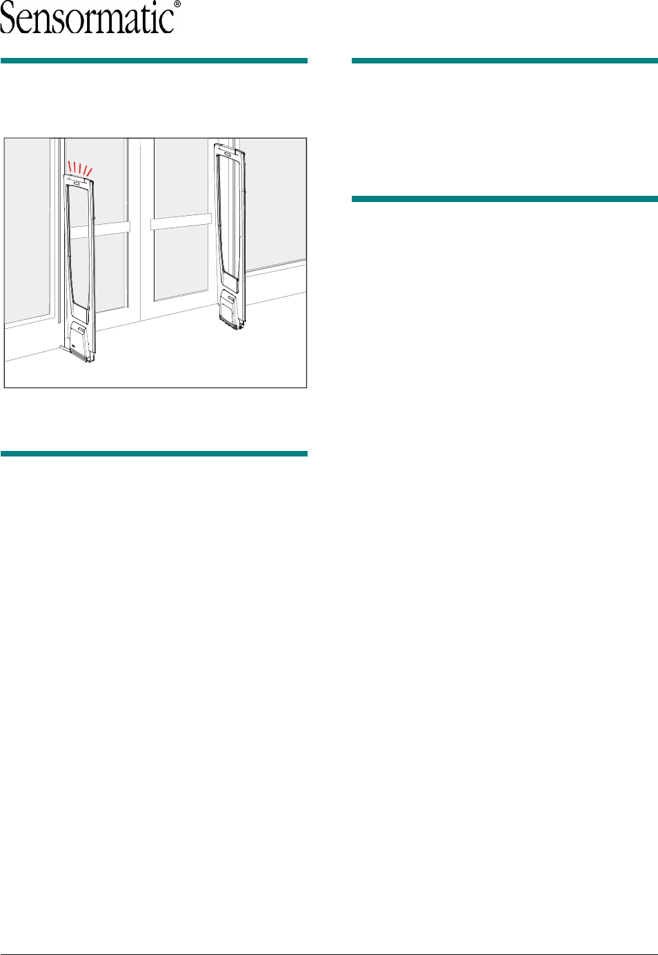
• Alarm indication. The top cap of the primary
pedestal contains flashing LEDs; the base
cover of the primary pedestal contains a piezo
for an audio alarm. The volume of the audio
alarm is controlled with a pot (RV3) on the main
circuit board in the primary base cover.
• Transmit inhibit. The base of the primary
pedestal has a hole that provides access to a
transmit-inhibit pushbutton.
• Tags Too Close indication. If this feature is
enabled by the configurator, the pedestal will
flash a unique alarm pattern when a non-
deactivated label or tag is left in the detection
field of the detector for awhile.
• Adjacent transmitter interference reduction.
This feature allows service to adjust the Energy
Trim Level to decrease the impact of electronic
noise from nearby anti-theft systems.
• Backfield reduction. If enabled by the
configurator, the detector will reduce the size of
the detection field behind the pedestals.
• Simplified design. AMS-1140 detectors are a
simplified design and do not support the
following features or options: people-counting,
relays, auto-phase, wired sync, jammer detect,
auxiliary receivers, remote alarms and external
alarm counters.
AMS-1140 DETECTORS 8200-2684-02, REV. 0
SETUP AND SERVICE GUIDE
2 of 15
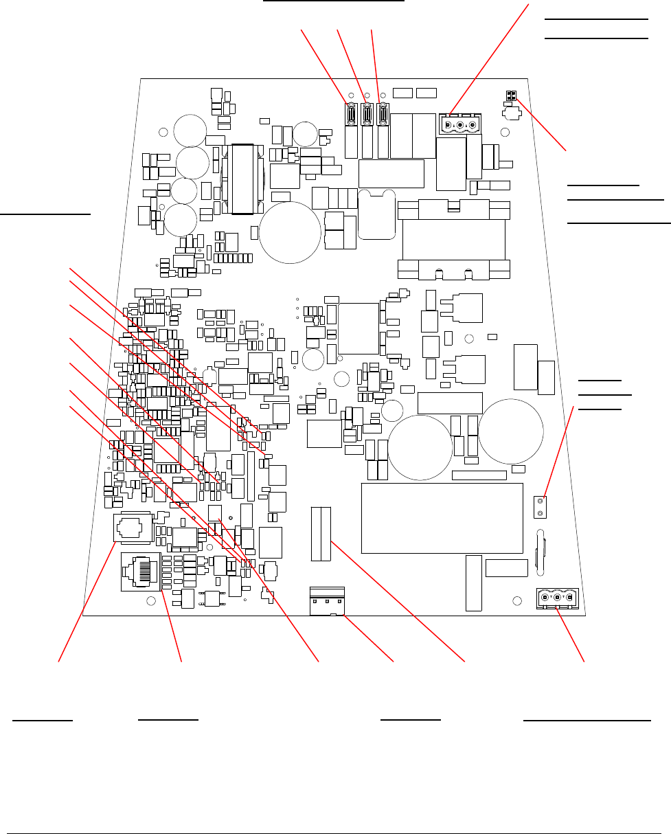
Figure 1. Primary pedestal main circuit board (0312-3072-01) pinouts
J6
J4
J3
J2
J5 RV3
P6
Primary Tuning Jumpers
Piezo
Volume
Pot
Interconnect Connector RS-485 Network Port Service Port
J1
Voltage
Selection
Jumper
Pin Signal
1 RS-232 RX
2 RS-232 TX
3 GND
4 GND
Pin Signal
1 RS-485 HI *
2 RS-485 LO *
3 SYNC HI
4 NOT USED
5 NOT USED
6 SYNC LO
7 GND
8 GND
P5
P3
Tx Coil Connector
Alarm Board
Cable Connector
Pin Signal Color
1 TX White
2 GND Shield
3 TX RETURN Black or Red
DS4
DS5
DS3
DS1
DS2
DS7
DS6
F1
Fuse Line Input
Pin Signal
1 NEUTRAL
2 GND
3 LINE
P4
1
Pin Signal Color
1 TX White
2 GND Shield
3 TX RET Black
1
1
1
Pin Signal Color
1 GND Shield
2 ALARM Black
3 Unused
4 +12V Red
Status Jumpers
(See Figure 5 for
close-up).
AMS-1140 DETECTORS 8200-2684-02, REV. 0
SETUP AND SERVICE GUIDE
3 of 15
Circuit Board Pinouts
The AMS-1140 pedestals each have a circuit
board in their bases. Figure 1 and Figure 2 show
the location of connectors, LEDS, jumpers, and
fuses, as well as pinouts for the connectors.
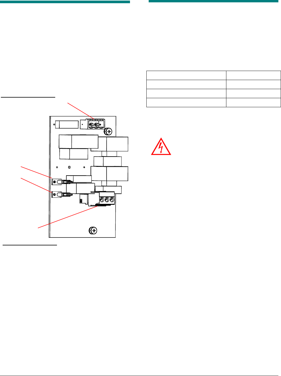
Figure 2. Secondary pedestal capacitor board
(0312-3075-01) pinouts
Service Procedures
This section covers the setup and service of the
AMS-1140 detector.
Field Replaceable Units
The AMS-1140 has the following Field
Replaceable Units (FRU):
Secondary capacitor board 0312-3075-01
Interconnect cable 0652-0506-01
Pedestal installation kit 0352-0444-01
Alarm lens installation kit 0352-0444-02
Replacing the Secondary Cap
Board
WARNING—RISK OF ELECTRIC
SHOCK! Disconnect AC power when
servicing.
1. Turn off power to the pedestal at the circuit
breaker.
2. Remove the cover from the exit side of the
secondary pedestal. To do this: loosen the four
fasteners at the base of the cover, and then lift
the bottom of the cover up and then off the
base.
3. On the secondary board, disconnect the Tx Coil
cable from connector P1 and the primary
pedestal from connectors P2. Pull on the
connectors, not the wires.
4. Loosen two fasteners securing the capacitor
board and remove it from the base cover.
Retain the insulator for the replacement board.
5. Use the two fasteners to secure the new
capacitor board to the base cover.
6. Reconnect the two cables to the capacitor
board.
7. Put the cover back on the base, ensuring that
you do not pinch any cables.
8. Tighten the four screws holding the base cover.
Tx Coil Connector
Interconnect
cable connector
Secondary
Tuning jumpers
1
P1
J2
P2
J1
1
Pin Signal Color
1 TX White
2 GND Shield
3 TX RETURN Black
Pin Signal Color
1 TX White
2 GND Shield
3 TX RETURN Red or Black
ULTRA•POST DETECTORS WITH SWITCHED MODE TRANSMITTER 8000-2595-07, REV. E
SETUP AND SERVICE GUIDE
4 of 15
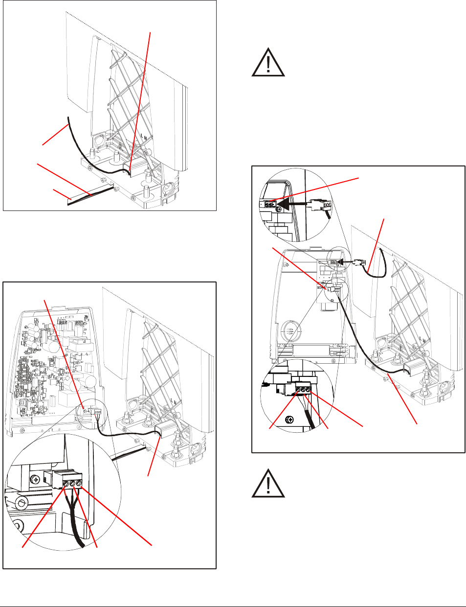
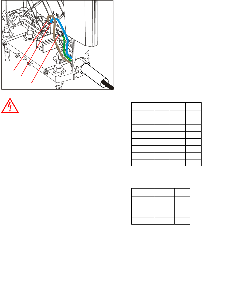
Replacing the Interconnect Cable
1. Route the interconnect cable through the
interconnect cable entry hole on each pedestal.
The end of the cable that has been stripped
and has heat shrink goes to the primary
pedestal; the other end goes to the secondary.
2. Route the interconnect cable through the
Interconnect cable entry port on the primary
pedestal. Make sure you have the end of the
cable that has been stripped and has heat-
shrink tubing.
CAUTION: Do not coil any cable inside
the base of the primary pedestal.
3. Connect the interconnect cable to the
connector plugged into P6 on the main board.
4. Cut the interconnect cable to the proper length,
allowing 15cm (6in) of extra cable for future
servicing. Strip the ends of the interconnect
cable wires.
CAUTION: Do not coil any cable inside
the base of the secondary pedestal.
5. Connect the interconnect cable to the
connector plugged into P1 on the capacitor
board in the secondary pedestal. Unlike some
other detectors, the secondary pedestal must
be connected to the primary in order for the
system to work properly.
Interconnect cable
entry hole
Interconnect
cable
Trench
P6
Pin 1
White
Pin 3
Black or Red
Pin 2
Ground
Interconnect cable
entry port
P1
Pin 1
White
Pin 3
Red or Black
Pin 2
Ground
P2
Interconnect
cable
Transmitter
cable
AMS-1140 DETECTORS 8200-2684-02, REV. 0
SETUP AND SERVICE GUIDE
5 of 15
Installing the Pedestal
Installation Kit
The pedestal installation kit contains eight wedge
anchors to secure the pedestals to a concrete
floor, four hole plugs, two metal plates, one voltage
selection jumper, and three conduit clamps.
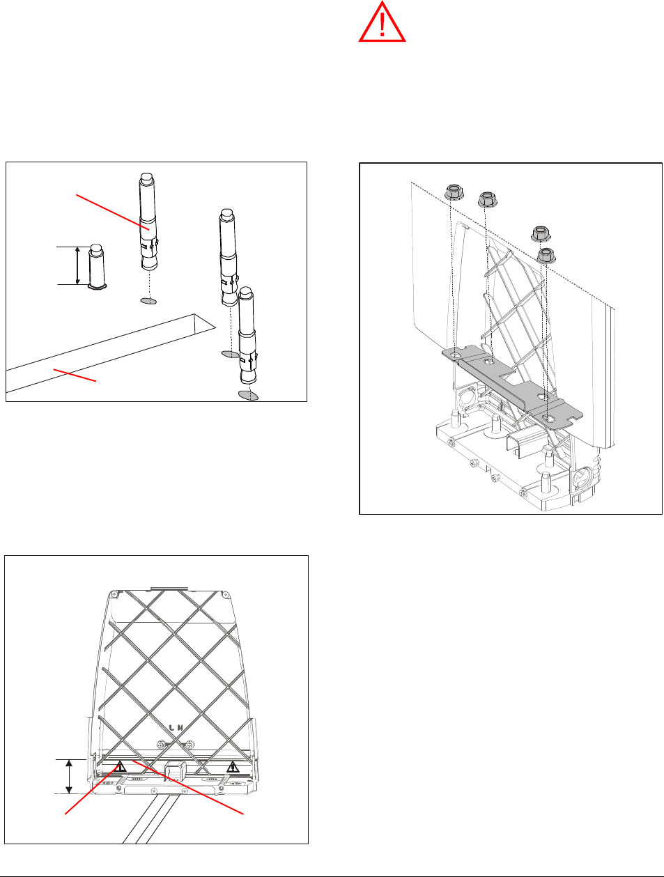
Installing the wedge anchors and metal
plate
1. Insert the mounting bolts into holes for each
base with the threaded end up. The exposed
portion of the bolt should be about 2.5cm (1in)
in length but must not exceed 3.4cm (1 3/8in).
Exposed portion of bolts should be measured
from the top of the floor surface (for example,
carpeting or wood).
2. Put each pedestal on its bolts.
WARNING: The tops of the bolts must
not be higher than the interference line
that appears above the alert symbol
(shown above) that is on the back of the
compartment. If the bolts are higher than
the line they will interfere with the main
circuit board when you install the primary
base cover.
3. Gently hit the top of each bolt with a hammer
to set the anchor.
4. Put a metal plate, which is in the pedestal
installation kit, over the bolts in each pedestal.
5. Secure the pedestals to the floor with the nuts
and washers from the pedestal installation kit.
2.5cm
(1in)
Cable trench
Mounting bolt
Interference line Alert symbol
3.45cm
(1 3/8in)
ULTRA•POST DETECTORS WITH SWITCHED MODE TRANSMITTER 8000-2595-07, REV. E
SETUP AND SERVICE GUIDE
6 of 15
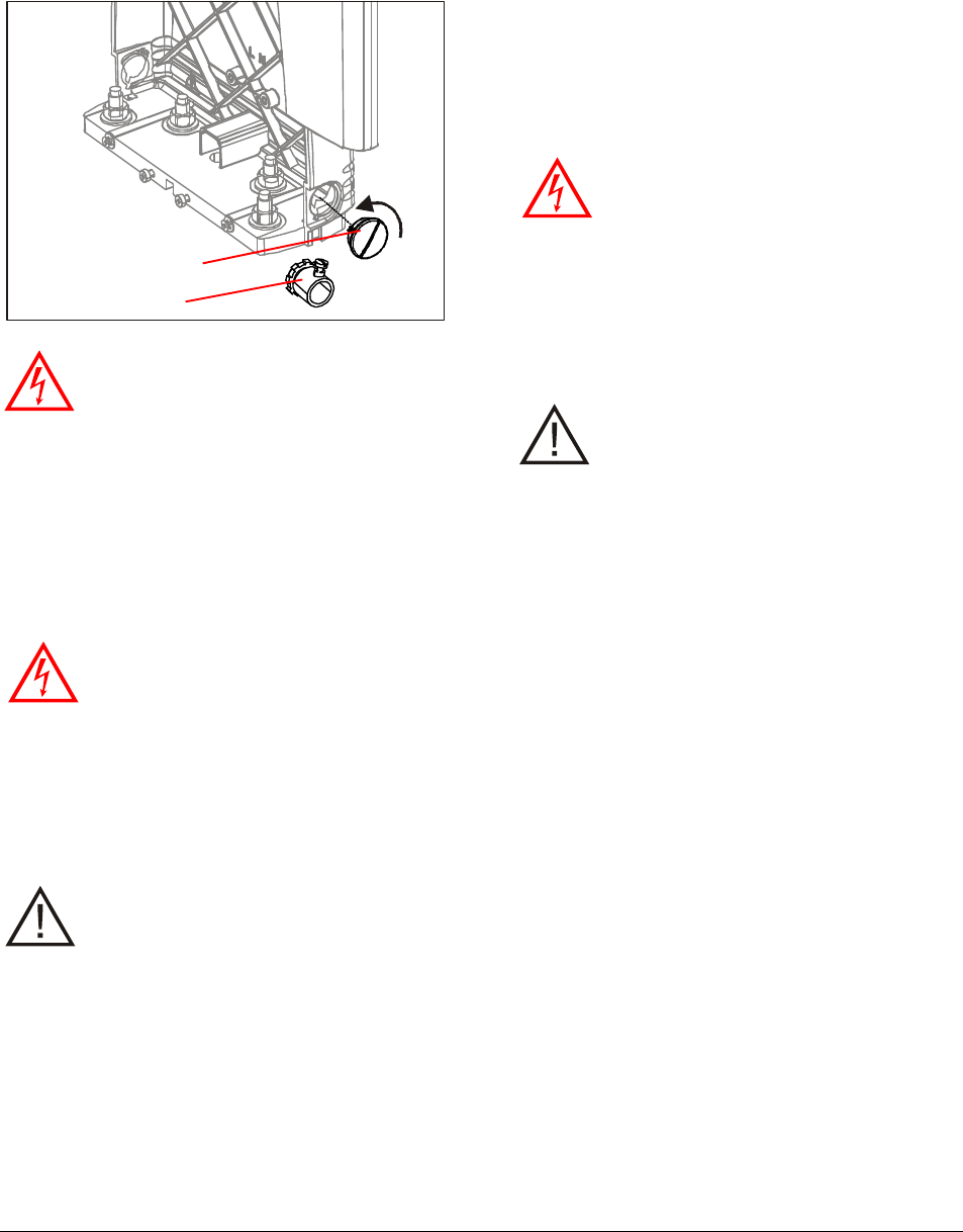
Installing the hole plugs and conduit
clamps
WARNING! DO NOT run the power
cable and the Interconnect cable in the
same conduit or raceway.
The hole plug and conduit clamps are installed in
the side of the pedestal base.
Installing the voltage selection jumper
You must set the voltage selection jumper (J1) on
the lower right side of the main circuit board to the
proper setting. Refer to Figure 1. The default
setting is for 240Vac.
WARNING—RISK OF ELECTRIC
SHOCK! Disconnect AC power when
servicing.
• For 120Vac operation, install the jumper
on J1. The jumper is in the pedestal
installation kit.
• For 240Vac operation, remove the jumper
from J1 if it is installed.
CAUTION: If you install the jumper for
120Vac and connect the pedestal to a
240Vac supply, the system will be
damaged.
If you set a pedestal to 240Vac and connect it to
120Vac power, the system will not operate
properly. Also, the system will generate a low
current error condition message (error number 21)
that can be read with the service configurator
software.
Replacing the Alarm Board and
Lens
The alarm lens installation kit (0352-0444-02)
contains two alarm lens (one for each pedestal),
the alarm board, and six screws. You use four of
the screws for the two alarm lens. The other two
screws are for the grounding plate in the base;
they are not needed.
WARNING—RISK OF ELECTRIC
SHOCK! Disconnect AC power when
servicing.
1. Remove the two screws on the top of the alarm
lens.
2. Lift the alarm lens.
3. Disconnect the alarm cable from the alarm
board.
CAUTION: The alarm board is fragile;
use caution when handling it.
4. Connect the alarm board to the alarm cable
connector on the top of the primary pedestal
5. Remove the adhesive backing and stick the
alarm board to the center of the top of the
pedestal. Make sure you align the arrow on the
alarm board with the groove on the top of the
pedestal. Note: the pedestal top has a slight
depression for the alarm board but the alarm
board overlaps it when the arrow on the alarm
board is properly aligned with the groove.
Conduit clamp
Hole plug
AMS-1140 DETECTORS 8200-2684-02, REV. 0
SETUP AND SERVICE GUIDE
7 of 15
Replacing the Fuse
WARNING—RISK OF ELECTRIC
SHOCK! Disconnect AC power when
servicing.
1. Turn off power to the pedestal at the circuit
breaker.
2. Remove the cover from the exit side of the
primary pedestal. To do this: loosen the four
fasteners at the base of the cover, and then lift
the bottom of the cover up and then off the
base.
3. Remove the cover over the fuse at F1. See
Figure 1 for the location of the fuse.
4. Replace blown fuse F1 with the type and rating
marked on the board.
5. Replace the fuse cover.
6. Secure the base cover back on the pedestal.
Inhibiting the Transmitter
Use the transmit-inhibit circuit to determine the
cause of unexplained alarms. If the alarm
continues when the transmitter is disabled,
interference is the likely cause. If the alarm stops
when the transmitter is disabled, tags placed too
close to the detector are the likely cause.
The transmitter can be inhibited by pressing
pushbutton S2 through the hole in front of the base
cover on the primary antenna. See the procedure
below for instructions on how this works.
Figure 3. Tx-inhibit pushbutton access hole
1. Using a pointed instrument such as a
straightened paper clip, press the pushbutton.
Note: A beep occurs each time S2 is pressed.
The software configurator can disable this
feature.
2. Press S2 once to disable the transmitter for 30
seconds (the power LED at the center of the
board will flash rapidly).
3. Press S2 a second time within 30 seconds to
disable both transmitter and alarm circuits
indefinitely (power LED stays on continuously).
This prevents continuous alarms until the
detector can be serviced.
4. Press S2 a third time to return the detector to
routine operation (power LED flashing once per
second).
Using the Software Configurator
An AMS-1140 detector can be serviced using the
AMS-1140 configurator, which is a software
program that runs on a portable (laptop) computer.
You can use the configurator at initial installation to
modify some aspects of the system’s operation per
a customer’s request, but the configurator is
usually used to find out why a system is not
working properly and to make adjustments to it to
get it working again.
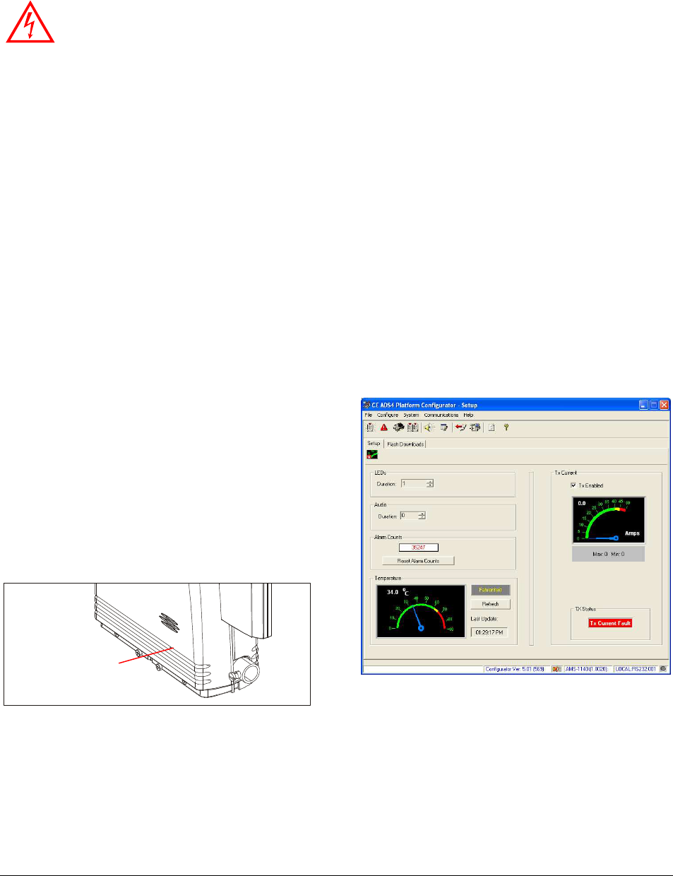
Figure 4. Configurator setup panel
You can make the following adjustments to modify
the system for a customer:
• Modify how long the LEDs flash and the audio
alarm sounds
• Enable the system to work with Active Tags,
which is a battery-powered tag that emits its
own alarm
Tx-
inhibit
pushbutton
hole
ULTRA•POST DETECTORS WITH SWITCHED MODE TRANSMITTER 8000-2595-07, REV. E
SETUP AND SERVICE GUIDE
8 of 15
• Enable (or disable) the Tags Too Close feature
so the pedestals silently alarm when a tag is left
nearby
• Enable (or disable) the reduction of the size of
the detection field behind the pedestals
You can use the configurator to find out the
following information to troubleshoot problems:
• How many times the system has alarmed
• The temperature of the air around the main
circuit board
• The current in the transmitter coils
• The status of the transmitter
• The amount of electronic noise the antenna
sees and the strength of a tag signal
• The frequency of the tag signal
• A report of past and current system errors and
runtime information
You can use the configurator to make the following
changes to the detector:
• Download software upgrades into the detector
• Disable the transmitter temporarily to check for
the source of false alarms
• Modify the Energy Trim level to decrease the
impact of electronic noise from nearby anti-theft
systems
• Adjust some operating parameters (Polarity,
Minimum Threshold, Sensitivity, and the Nulling
Pot) to reduce the effect of electronic noise the
antenna receives from the environment
• Enable (or disable) the Phase Lock Loop
feature to adjust for noise on the power line
• Change how the system synchronizes to the
power line
Note: Refer to the online help provided with the
configurator for a complete description of
configurator operation.
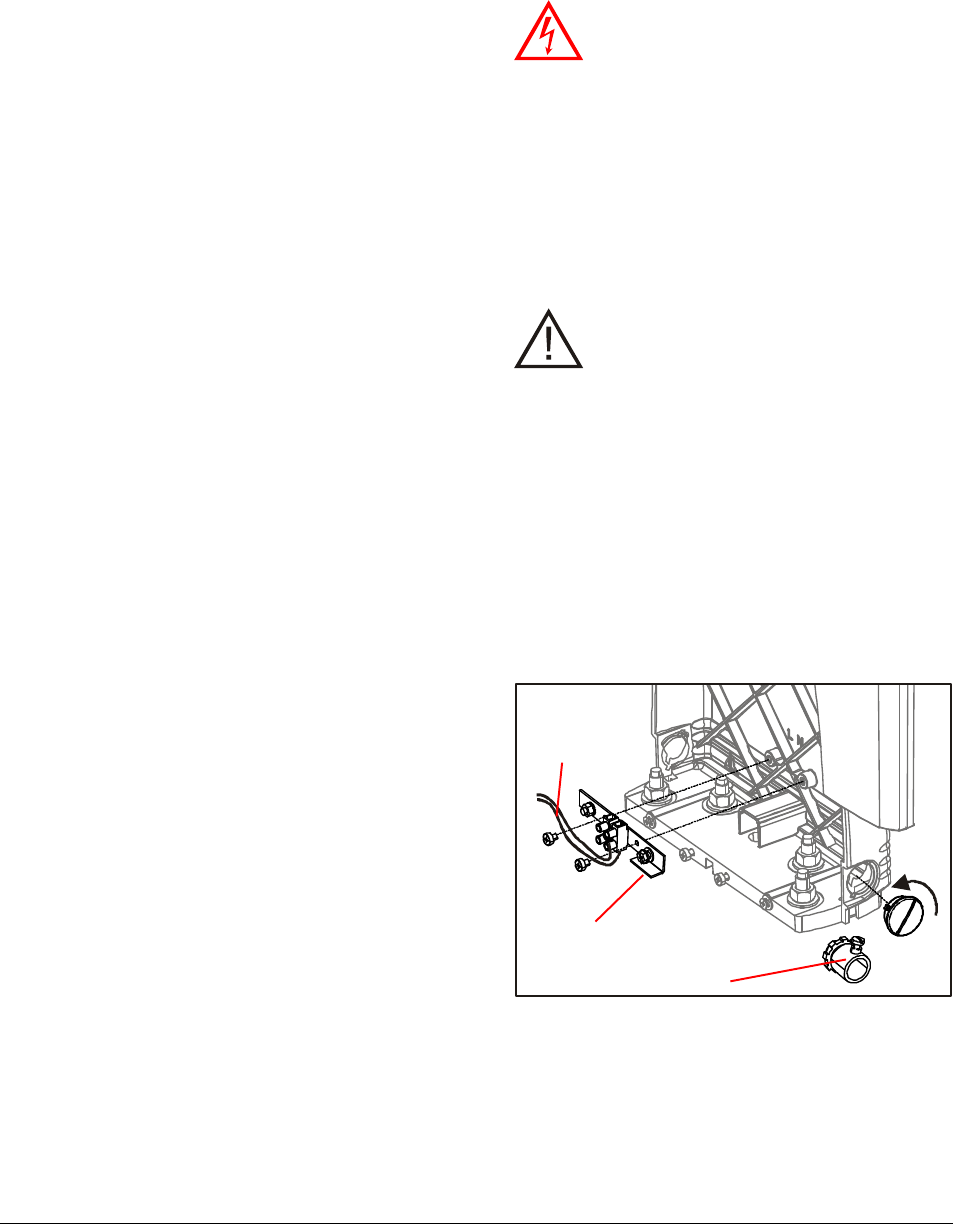
Connecting to AC Power
WARNING: RISK OF ELECTRIC
SHOCK! Make sure the primary pedestal
is disconnected from its power source
before you proceed.
1. Set the voltage selection jumper (J1) on the
lower right side of the main circuit board to the
proper setting. Refer to Figure 1 for the location
of the jumper. The default setting is for 240Vac
(no jumper). For 120Vac operation, install the
jumper in J1. The jumper is in the pedestal
installation kit.
CAUTION: If you install the jumper for
120Vac and connect the pedestal to a
240Vac supply, the system will be
damaged.
If you set a pedestal to 240Vac and connect it
to 120Vac power, the system will not operate
properly. Also, the system will generate a low
current error condition message (error number
21) that can be read with the service
configurator software.
2. Remove the cover from the exit side of the
primary pedestal. To do this: loosen the four
fasteners at the base of the cover, and then lift
the bottom of the cover up and then off the
base.
3. Use two screws from the alarm lens installation
kit to attach the grounding plate to the primary
pedestal. Do not unplug the cable from the
main circuit board on the base.
Grounding plate
Conduit clamp
Wires go to
primary base
cover
AMS-1140 DETECTORS 8200-2684-02, REV. 0
SETUP AND SERVICE GUIDE
9 of 15
4. Install the hole plug supplied in the pedestal
installation kit in the conduit access hole that
will not be used.
5. Install the steel conduit clamp supplied in the
pedestal installation kit.
WARNING! DO NOT run the power
cable and the Interconnect cable in the
same conduit or raceway.
6. Have a licensed electrician wire the primary
pedestal to power. The locations of where the
Line, Neutral, and Ground wires connect to the
grounding plate are shown above.
Tuning the Pedestals
Tuning the pedestals is not a standard part of initial
installation; the system should be left at the factory
default setting of minimum capacitance (all
jumpers out). If the pedestals are placed near a lot
of metal, however, the current in the system may
be reduced and the performance can be reduced.
If the performance is unacceptable and the
maximum burst current is not at least 30A, you can
use the following procedure to optimize the tuning
until maximum peak current is achieved.
1. Remove the base covers on both pedestals
and locate the tuning jumpers on the main
circuit board on the primary pedestal and the
secondary capacitor board. See Figure 1.
• Primary tuning jumpers: J2, J3, J4
• Secondary tuning jumpers: J1, J2
2. Ensure the tuning jumpers are set to their
default values. See Table 1 (primary) or
Table 2 (secondary).
3. Adjust the tuning jumpers on the primary
pedestal up one step (for example, from Step
0 to Step 1).
4. Check the current.
• If the current is less than before you adjust
the capacitance, you are detuning the
pedestal. Return to the default setting. You
are done.
• If the current goes up, you are tuning the
pedestal in the correct direction. Keep
adding capacitance until you find the peak
current.
5. If you get to step 8 in Table 1 (all jumpers in)
and the current is still increasing, go to the
secondary pedestal and increase the
capacitance one step. Then go back to the
primary pedestal, set it back to step one (all
jumpers removed) and start adding
capacitance on the primary one step at a time.
Table 1. AMS-1140 Tuning Table (Primary)
Step # J4 JW3
JW2
1* 0 0 0
2 0 0 1
3 0 1 0
4 0 1 1
5 1 0 0
6 1 0 1
7 1 1 0
8 1 1 1
* Default
Table 2. AMS-1140 Tuning Table (Secondary)
Step # J2 J1
1* 0 0
2 0 1
3 1 0
4 1 1
* Default
Line
Neutral
Ground

ULTRA•POST DETECTORS WITH SWITCHED MODE TRANSMITTER 8000-2595-07, REV. E
SETUP AND SERVICE GUIDE
10 of 15
Troubleshooting
Checking Detector Operation
DO NOT perform the following
procedure until you have thoroughly
reviewed configurator software settings.
1. Verify all boards are properly seated and all
cables are securely plugged in.
2. Turn on the circuit breaker.
3. Connect the laptop computer to J5 on the main
circuit board and load the configurator.
Note: After power is applied the detector
passes its power-up test, the power
on/heartbeat LED (DS2) should start flashing
once per second. If it does not flash, check for
an error condition using either the laptop
computer or by observing LED DS5 on the
board. Refer to Figure 5 for the location of DS2
and DS5. Refer to the section entitled
“Understanding Error Codes” on page 11 for
interpretation of the codes.
4. Close the base cover and verify the transmit
current is at least 25A. If it is less than 25A, go
to the section “Tuning the Pedestal” on page 9.
5. Check the following:
• If validations occur with no tags/labels
nearby, increase the Minimum Threshold or
change the Sensitivity in 1dB increments
until validations cease.
• If this Ultra•Max detector is causing another
to constantly alarm or not detect, or vice
versa, check the System Noise Average
screen. If the bar meters are constantly
reaching the maximum values, then adjust
the Zero Crossing Delay.
• Check the vicinity for tags or labels.
• If a lot of noise is entering the detector but it
is lower when the Polarity of the detector is
set to “Figure-8” than when it is set to
Aiding, set the Polarity to “Figure-8”.
• Set audio and LED durations.
6. Disconnect the laptop cable. Detector operation
has now been verified.
Dead system/Low sensitivity
A detector that is dead or has low sensitivity may
be without power, in the wrong mode, or affected
by noise from an electronic device such as a TV
set or PC monitor, or from certain fluorescent,
halogen, or neon lamps. To diagnose the problem,
you use the Mode LED (DS2) inside the primary
base cover. Refer to Figure 6 for the location of
DS2.
1. Observe the Mode LED (DS2). In what state is
the lamp?
• Off - No power
• Steady (not flashing) – Service Mode
• Flashing twice a second – Hidden Tag Mode
• Flashing once a second – Normal Mode
2. Use the following table to determine the
problem/action to take.
Statu
s
Problem/Action
Off The detector has no power.
1. Ensure the detector is connected
to the AC power source.
2. Check the circuit breaker in the
store’s breaker box. If the
breaker tripped, reset it and
check system performance. If the
breaker will not stay on, call
maintenance. If the breaker is
OK, the detector needs service.
Call for assistance.
Flashing twice
per second Detector is in Hidden Tag Mode.
1. Wait 30 seconds for the detector
to revert to Normal Mode.
2. Use a tag to test the system for
sensitivity. If the detector still has
low sensitivity, see “Flashing
once per second” below.
On steady (not
flashing) Detector is in Service Mode.
1. To change detector to normal
mode, insert a paper clip into the
Tx-inhibit pushbutton access hole
(
Figure 3
) and press the switch
once.
2. Test the detector for sensitivity
with the tag/label. If the detector
still has low sensitivity, see
“Flashing once per second”
below.
Flashing once An electronic device or a lamp may
be causing interference. One at a
!
!!
!

AMS-1140 DETECTORS 8200-2684-02, REV. 0
SETUP AND SERVICE GUIDE
11 of 15
per second time, turn off each device or lamp
within 3m (10ft) of the pedestals and
use a tag to test sensitivity. If
sensitivity improves when a device is
turned off, that is the interference
source. Leave the device off or move
it away from the receiver antennas. If
sensitivity does not improve, call for
assistance.
False Alarms
Nearby electronic devices or hidden tags/labels
can cause the detector to false alarm.
1. To help diagnose the problem, the detector has
a Mode LED DS2 (Figure 5). In what state is
the lamp?
• Flashing once a second – Normal Mode
• Steady (not flashing) – Service Mode
• Flashing twice a second – Hidden Tag
Mode
2. Does pedestal alarm constantly or just
sometimes—twice a minute or less?
• Sometimes. Go to step 3.
• Constantly. Go to step 4.
3. Move all store products 3m (10ft) from
pedestal. Do alarms stop?
• Yes. One or more moved products have a
tag/label. Find and remove it, you are done.
• No. Look for tags/labels within 3m (10ft) of
pedestals. If no tags/labels are found and
problem persists, go to step 6.
4. Place the alarming pedestal in Hidden Tag
Mode by inserting the end of a paper clip into
the Tx-inhibit access hole (Figure 3) and
pressing the switch once. The pedestal should
emit a three second tone and enter Hidden Tag
Mode and the mode LED DS2 should flash
rapidly. (If not, this feature has been disabled.
Go back to step 3.) After 30 seconds, Hidden
Tag Mode reverts to Normal Mode.
Do alarms occur during the 30 seconds Hidden
Tag Mode is on?
• No. Go to step 5.
• Yes. Go to step 6.
5. After the Hidden Tag Mode completes, do
alarms resume?
• Yes. One or more tags/labels are still in the
area. Find and remove them, you are done.
• No. Ensure you waited 30 seconds and
then check mode light to ensure pedestal is
not in Service Mode. If it is in Service Mode,
press the mode switch once more to return
to Normal Mode and go back to step 1. If it
is not in Service Mode, wait until the system
false alarms again before performing this
procedure.
6. A nearby device such as a TV set or computer,
or a neon or halogen lamp may be causing
false alarms. One at a time, turn off each
device or lamp within 3m (10ft). Do alarms stop
when the device or lamp is off?
• Yes. That device or lamp is the source of
the false alarms. Leave the device or lamp
off or move it away from the receiver
antennas. If you cannot, see “No” below.
• No. Call for assistance. Place the pedestal
in Service Mode to stop the alarm until
service arrives by inserting the end of a
paper clip into the Tx-inhibit switch access
hole (Figure 3). If the pedestal is in the
Normal Mode, press the mode switch twice;
otherwise, press the mode switch once.
The mode LED should stay on
continuously.
Understanding Error Codes
When the system encounters an error, it generates
one of two types of error codes:
• Recoverable – these errors are not as
serious as fatal errors. The system
continues to transmit but an error code is
stored in a log in RAM memory. If the
system shuts down, the error codes will be
lost.
• Fatal – this type of error is more serious
than the recoverable errors. The system
stops transmitting, displays the error three
times on the system error LED (DS5), and
logs the error code in a log in non-volatile
memory (NVM). The system usually tries
to reset itself but it may be unsuccessful.
The list of error codes is shown in Table 3. These
codes are displayed on the System Error LED
(DS5). A history of the errors can viewed using the
configurator.
ULTRA•POST DETECTORS WITH SWITCHED MODE TRANSMITTER 8000-2595-07, REV. E
SETUP AND SERVICE GUIDE
12 of 15
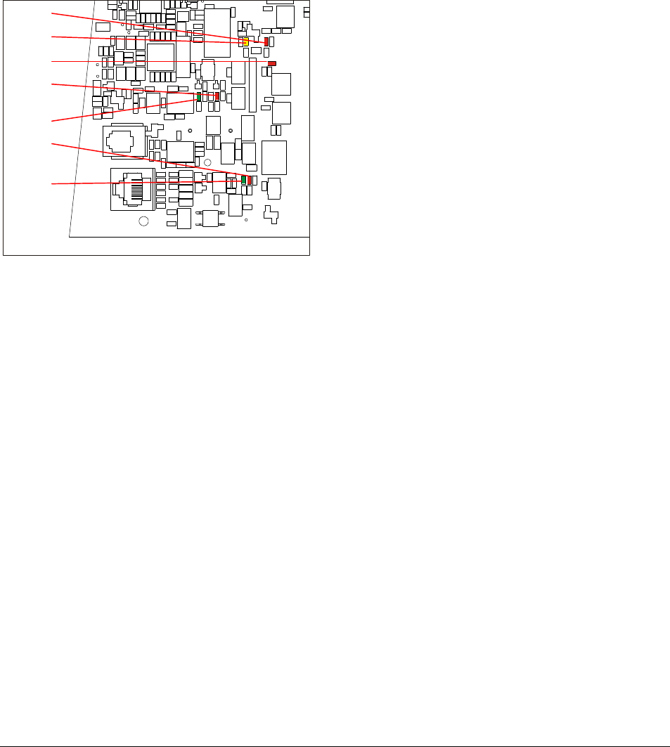
Interpreting LED Indicators
LED indicators on the receiver board can be used
for diagnostic purposes. During the power-on self-
test, all LEDs flash simultaneously to test their
function, then they light in sequence to indicate the
progress of the power on self-test. Figure 5 shows
the location of the status LEDs.
Figure 5. LED locations
• DS1 (red) is the alarm indicator.
• DS2 (green) is the mode/power/heartbeat
indicator, which shows that the board is
powered and what mode the system is in
(Normal/Hidden Tag/Service).
• DS3 (red) is the frequency rejection indicator. If
this LED is lit, the pedestal has detected an out-
of-frequency label, such as a deactivated or
wounded label, in the vicinity.
• DS4 (red) is unused.
• DS5 (yellow) is the validation/system error
indicator. This LED flashes in a coded
sequence whenever the board fails the power
on self test, or run-time diagnostic tests, or
when a serious failure interrupt occurs. To
indicate an error code, the DS5 error LED on
the receiver board will flash a number of times,
pause, then flash again a number of times. For
example: DS5 flashing three times, pausing,
then flashing two times indicates error code 32.
Error codes are listed in Table 3.
• DS6 (green) indicates that data is being
received on the Network RS-485 port.
• DS7 (red) indicates that data is being
transmitted on the Network RS-485 port.
DS4
DS5
DS3
DS1
DS2
DS7
DS6

AMS-1140 DETECTORS 8200-2684-02, REV. 0
SETUP AND SERVICE GUIDE
13 of 15
Table 3. AMS-1140 error codes
Alert Code Action
11 Illegal Instruction Not applicable
12 Unimplemented Interrupt Not applicable
13 NVM Write Failed Fatal error. Replace main circuit board
14 Invalid Device Fatal error. Replace main circuit board
15 Sequence Table Error Not applicable
16 Out of Memory Not applicable
17 Undecided: No Split Not applicable
18 Watchdog: Task Reset Recoverable. First, try resetting the NVM to its defaults. If problem
persists, reinstall application software. If problem persists, replace main
circuit board.
21 Current Sense Antenna A Recoverable. Retune antennas
22 Current Sense Antenna B Not applicable
23 Power Supply Overtemp
Fault Recoverable. Replace main circuit board.
24 Transmitter Failsafe
Fault, Burst Too Long Recoverable. Replace main circuit board.
25 Receiver samples
exceeded the Receiver
buffer
Recoverable. Reinstall application software
26 TX PWM Fault Fatal error. Check for large amounts of metal in vicinity of the pedestals.
If this is not the cause and error keeps occurring, replace the main circuit
board.
27 HW Current Fault Fatal error. If the error keeps occurring, replace the main circuit board.
28 Tx Shutdown Not used.
29 SW Current Fault Fatal error. This error is caused by an over-current condition. This is
probably caused by hardware. This could be caused by a damaged main
circuit board or a short in the coil wiring, for example.
31 Missing Zero Crossing
Signal Recoverable. Check the AC line quality. If it is OK, replace the main
circuit board.
32 Missing External Zero
Crossing Signal Recoverable. This occurs when Universal Sync has been selected as the
Sync source in the configurator but no signal is received. Check the
connection on the RS-485 connectors on the receiver board and the
signal source.
33 Invalid Line Frequency at
Power/Up Recoverable. This can be caused by noise on the AC power line. Check
the AC line quality.
34 Invalid Power Supply
Type at Powerup Not applicable
35 Wired Sync: Missing
Signal Not applicable
36 Unknown Voltage ID
selection assuming
58kHz
Fatal. Replace main circuit board.
37 Line PLL Unlocked Recoverable. This can be caused by noise on the AC power line. Check

ULTRA•POST DETECTORS WITH SWITCHED MODE TRANSMITTER 8000-2595-07, REV. E
SETUP AND SERVICE GUIDE
14 of 15
the AC line quality.
41 Jammer Event Detected Not applicable
44 Host Communication
Mailbox Full Recoverable. Reload the application software. If error is not eliminated,
replace the main circuit board.
45 LDM Power Save Active Not applicable
46 LDM Power Save Inactive Not applicable
51 No Reference Not applicable
52 Invalid Alarm Type from
detector Not applicable
53 NVM Checksum Error Recoverable.
54 NVM Reset Recoverable.
55 NVM Revision Change Recoverable.
56 People Counter Blocked
Sensor Detected Not applicable
57 Invalid Wired Sync
Command Received Not applicable.

AMS-1140 DETECTORS 8200-2684-02, REV. 0
SETUP AND SERVICE GUIDE
15 of 15
Specifications
Power Supply
Primary Input ........................................ 100-120Vac
or 200-240Vac @ 50-60Hz
Primary power fuse ........................... One 2A, 250V,
slo-blo, hi-breaking,
5mmx20mm fuse
Current draw .............. less than 0.5Arms @ 120Vac
Input power ....................................... less than 44W
Transmitter
Operating frequency ...................... 58kHz (+200Hz)
Transmit Burst Duration ................................. 1.6ms
Transmit Current (in Tx coil) ..................... 42A peak
Transmit Current (in Interconnect cable) .. 17A peak
Burst Repetition Rate:
Based on 50Hz ac .................................. 37.5Hz
Based on 60Hz ac ..................................... 45Hz
Antenna Coil Resistance ................ .25 ohms (±5%)
Receiver
Center Frequency .......................................... 58kHz
Alarm
Audio level ..................................................... 83dBA
Environmental
Ambient Temperature .. 0°C to 40°C (32°F to 104°F)
Relative Humidity .............0 to 90% non-condensing
Enclosure .......................................................... IPx0
Mechanical
Height .............................................. 137.1cm (54in)
Width ................................................. 35.8cm (14in)
Depth (base) ....................................... 8.6cm (3.4in)
Declarations
Regulatory Compliance
EMC ............................................... 47 CFR, Part 15
EN 300 330
EN 301 489
RSS 210
Safety .................................................... UL 60950-1
CSA C22.2.60950-1
EN 60950-1
REGULATORY PRODUCT NAME:
ZA1140-D = TYPE: AMS-1140
FCC ID: BVCAMS1140
FCC COMPLIANCE: This equipment complies with Part 15 of the
FCC rules for intentional radiators and Class A digital devices when
installed and used in accordance with the instruction manual.
Following these rules provides reasonable protection against harmful
interference from equipment operated in a commercial area. This
equipment should not be installed in a residential area as it can
radiate radio frequency energy that could interfere with radio
communications, a situation the user would have to fix at their own
expense.
EQUIPMENT MODIFICATION CAUTION: Equipment changes
or modifications not expressly approved by Sensormatic Electronics
Corporation, the party responsible for FCC compliance, could void
the user's authority to operate the equipment and could create a
hazardous condition.
Other Declarations
WARRANTY DISCLAIMER: Sensormatic Electronics
Corporation makes no representation or warranty with respect to the
contents hereof and specifically disclaims any implied warranties of
merchantability or fitness for any particular purpose. Further,
Sensormatic Electronics Corporation reserves the right to revise this
publication and make changes from time to time in the content hereof
without obligation of Sensormatic Electronics Corporation to notify
any person of such revision or changes.
LIMITED RIGHTS NOTICE: For units of the Department of
Defense, all documentation and manuals were developed at private
expense and no part of it was developed using Government Funds.
The restrictions governing the use and disclosure of technical data
marked with this legend are set forth in the definition of "limited
rights" in paragraph (a) (15) of the clause of DFARS 252.227.7013.
Unpublished - rights reserved under the Copyright Laws of the
United States.
TRADEMARK NOTICE: Ultra•Max and Sensormatic are
registered trademarks of Sensormatic Electronics Corporation. Other
product names (if any) mentioned herein may be trademarks or
registered trademarks of other companies.
No part of this guide may be reproduced in any form without written
permission from Sensormatic Electronics Corporation.
RWH 01/2010