Tyco Safety Sensormatic AMS9030 ANTI THEFT DEVICE User Manual AMS 9030 Controller Installation Guide
Tyco Safety Products/Sensormatic ANTI THEFT DEVICE AMS 9030 Controller Installation Guide
UserManual.wiki
>
Tyco Safety Sensormatic
>
AMS9030 User Manual
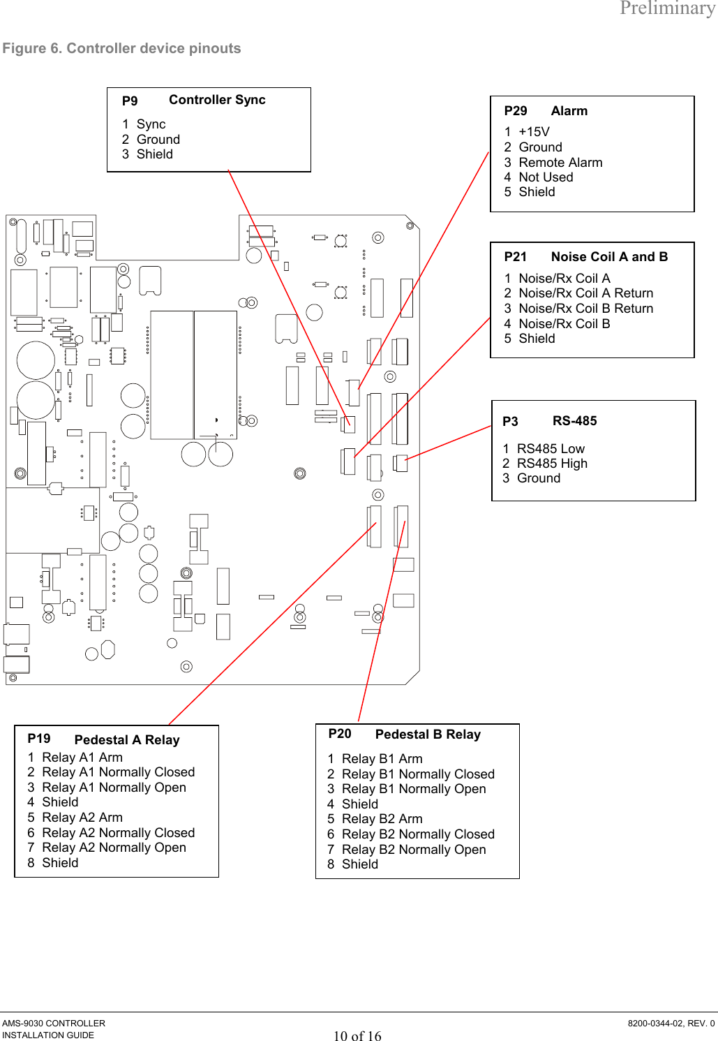
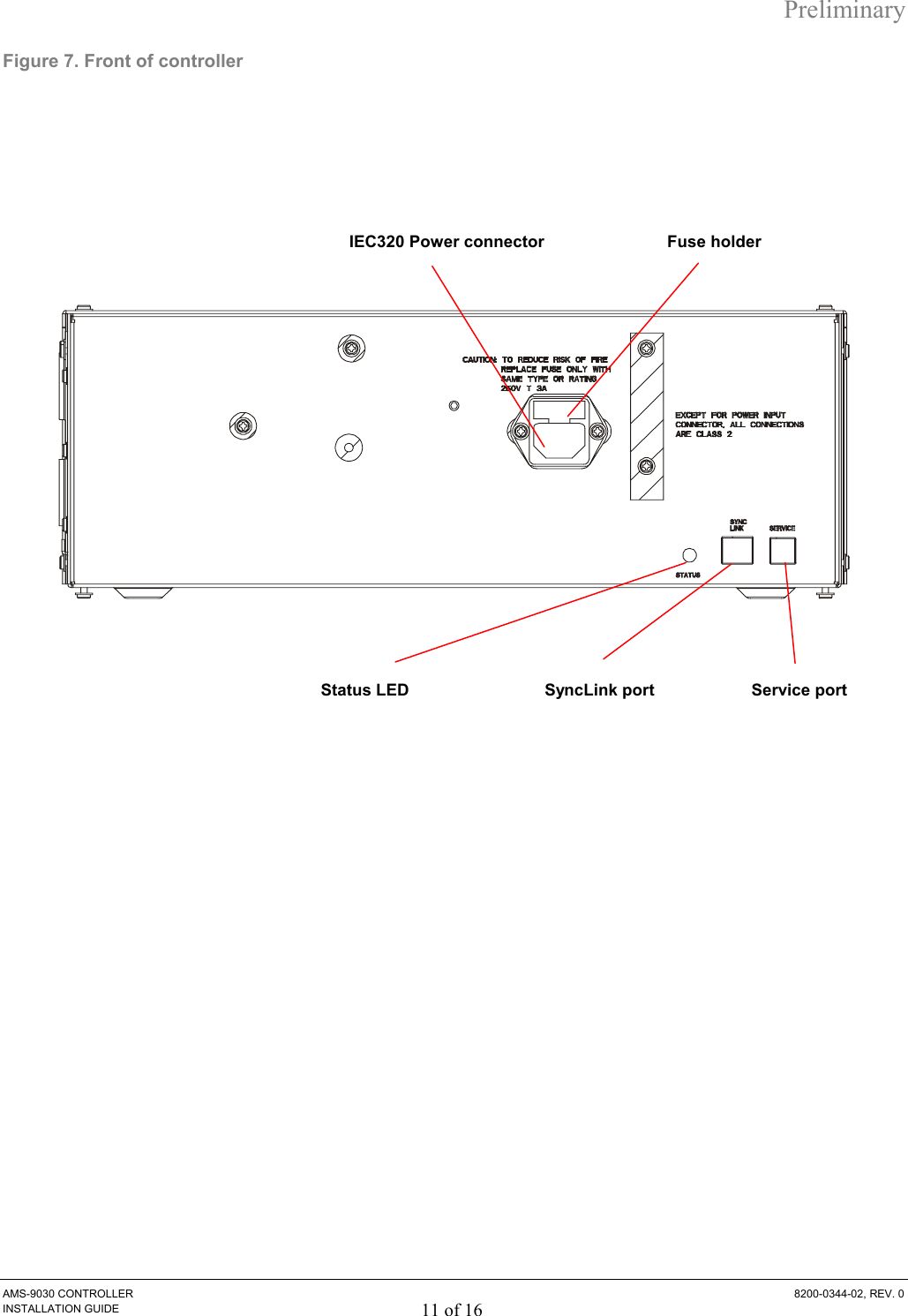
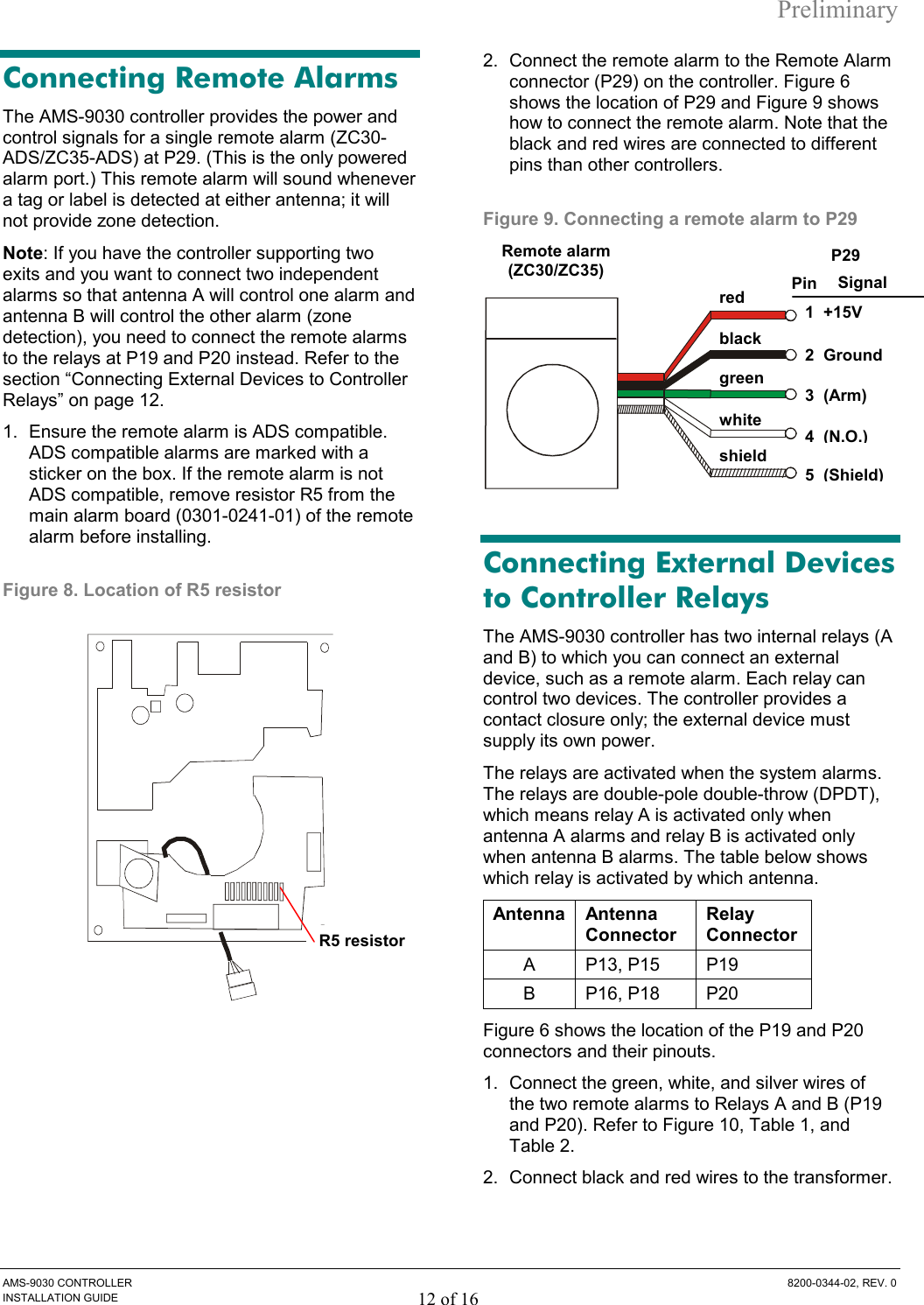
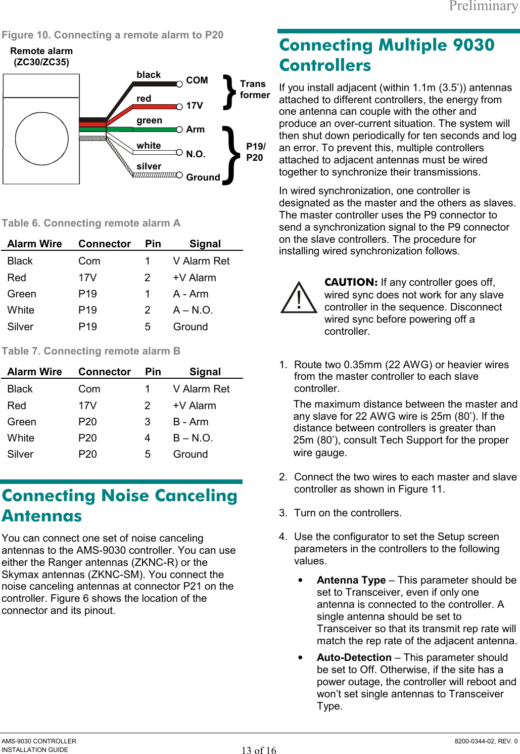
INSTALL GUIDE
Navigation menu
Upload a User Manual
Namespaces
Wiki Guide
HTML
PDF
Info
Views
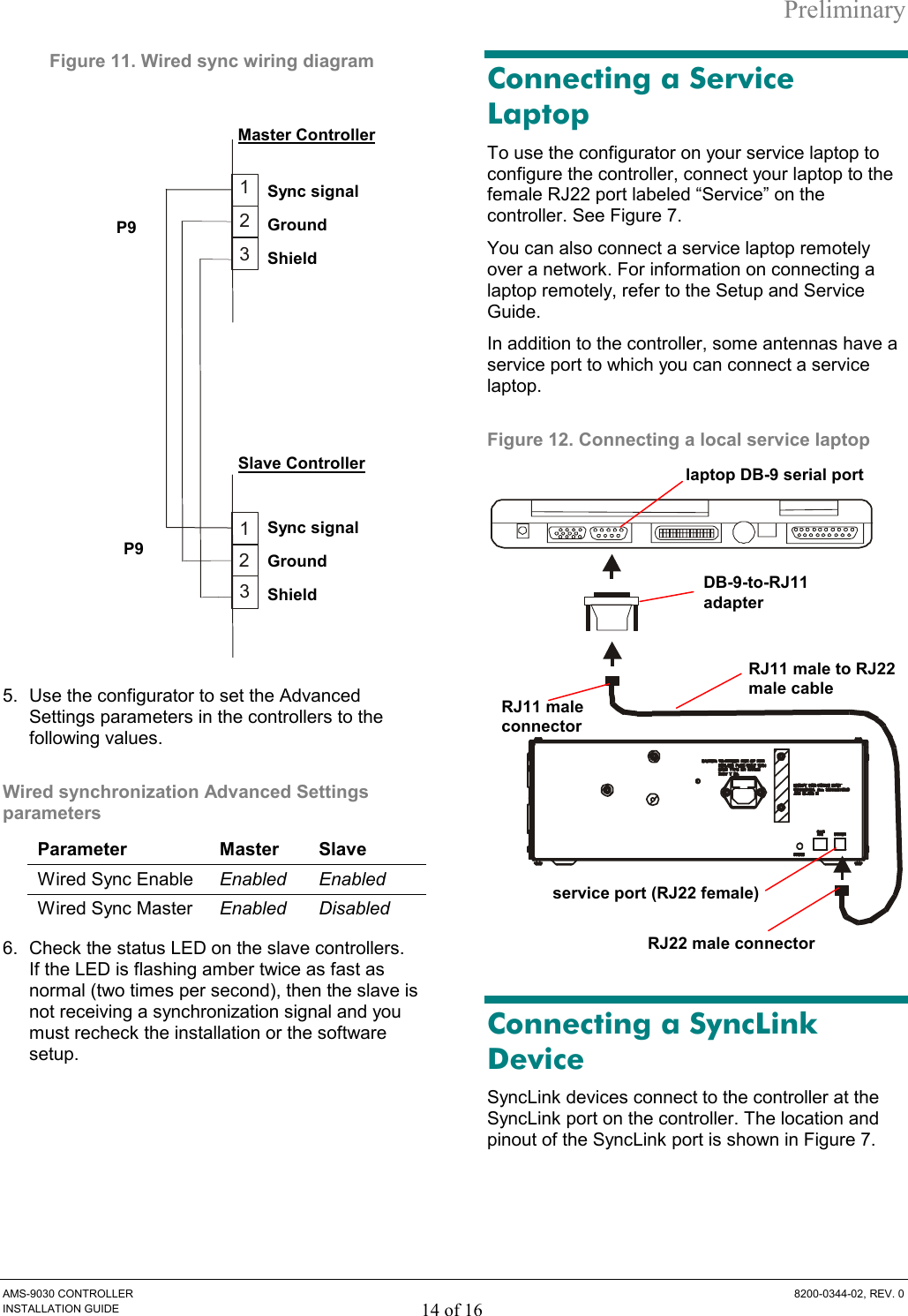
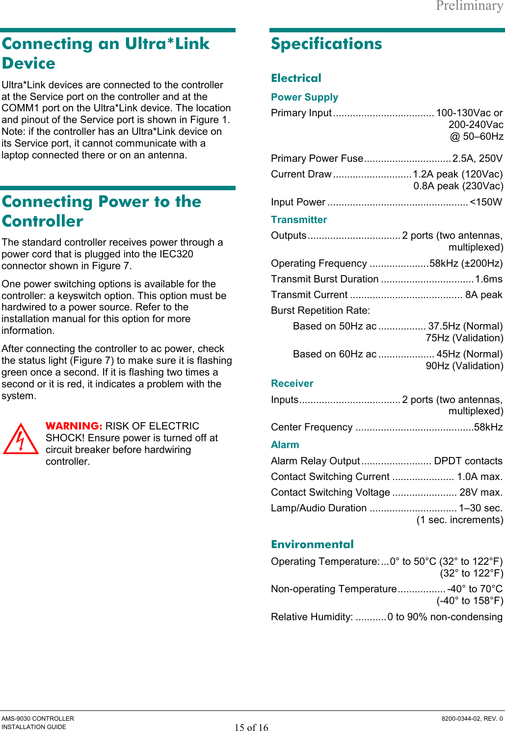
User Manual
Discussion / Help
Navigation