Tyco Safety Sensormatic AMS9030 ANTI THEFT DEVICE User Manual AMS 9030 Controller Installation Guide
Tyco Safety Products/Sensormatic ANTI THEFT DEVICE AMS 9030 Controller Installation Guide
INSTALL GUIDE
Preliminary
AMS-9030 CONTROLLER 8200-0344-02, REV. 0
INSTALLATION GUIDE 1 of 16
AMS-9030 Controller
Installation Guide
ZE9030
Contents
About this Guide .................................................... 1
Controller Overview ............................................... 2
Installation Requirements ...................................... 2
Mounting the Controller ......................................... 3
Connecting Antennas ............................................4
Connecting Remote Alarms................................. 12
Connecting External Devices to Controller Relays
............................................................................. 12
Connecting Noise Canceling Antennas ............... 13
Connecting Multiple 9030 Controllers.................. 13
Connecting a Service Laptop .............................. 14
Connecting a SyncLink Device............................14
Connecting an Ultra*Link Device......................... 15
Connecting Power to the Controller..................... 15
Specifications....................................................... 15
Declarations......................................................... 16
© Sensormatic 2004
About this Guide
This installation guide explains how to install the
AMS-9030 controller. Other related documents are:
• Planning Guide, 8200-0344-01
• Installation Guide, AMS-9030 Key Switch
Option Kit, 8200-0344-05
• Installation Guide, AMS-9030 Plenum Option
Kit, 8200-0344-06
• Setup and Service Guide, 8200-0344-08
• Reference Guide, 8200-0344-09
Note: Because customer requirements dictate the
placement of system components, your
Sensormatic representative will supply this
information separately.
Note to the Installer: If this product was installed
in a European Union or European Free Trade
Association member state, please give the
Declaration of Conformity included with this
product to the manager or user. By law, this
information must be provided to the user.
Note: There may be restrictions on the installation
of certain antennas in certain countries. Please see
the antenna installation guides for documentation
of the restriction.
Preliminary
AMS-9030 CONTROLLER 8200-0344-02, REV. 0
INSTALLATION GUIDE 2 of 16
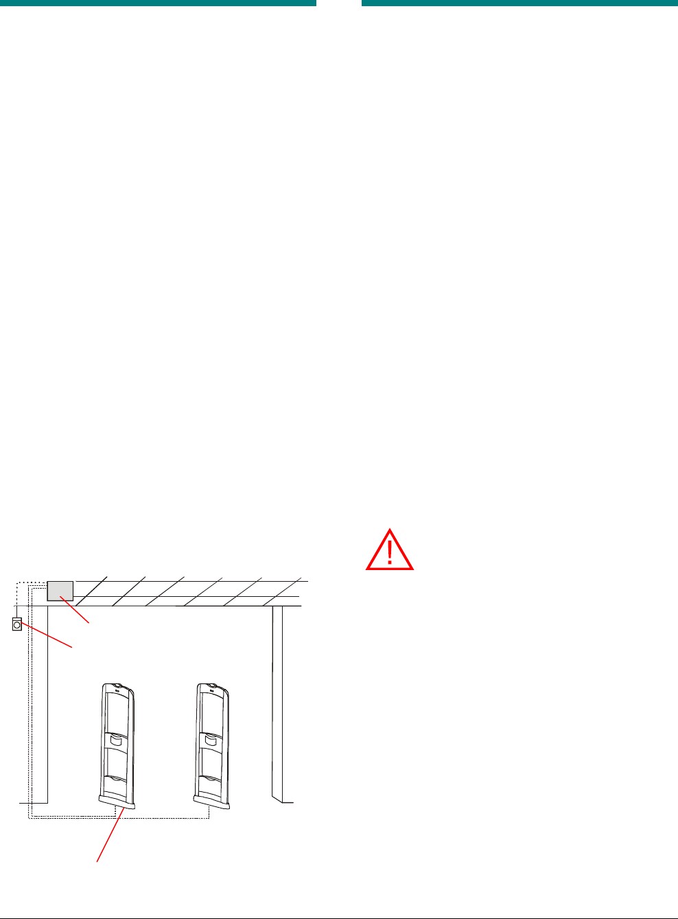
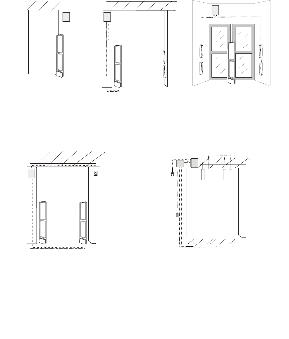
Controller Overview
An AMS-9030 controller is part of an Ultra•Max®
security label detector. The controller supports the
following system components, some of which are
shown in Figure 1:
• Two transceiver antennas or two pairs of Tx/Rx
antennas for tag and label detection.
• One remote alarm (optional), but the controller
supports two-alarm configurations with two
internal relays.
• Two noise canceling antenna kits to reduce the
effect of electro-magnetic interference
(optional).
• Four external devices, such as cameras,
activated by two relays in the controller
(optional).
• A service laptop for configuration and trouble-
shooting.
• A SyncLink transmitter to synchronize the
detectors with deactivators at the site
(optional).
• An Ultra*Link device (optional).
• An RS-485 network (optional). This manual
only describes how to connect a controller to
an RS-485 network. For information on setting
up an RS-485 network, refer to the AMS-9030
Setup and Service Guide.
Figure 1. AMS-9030 system components
Installation Requirements
Verifying Equipment and Unpacking
❑ Verify that all equipment has arrived. Make sure
the system configuration is the right one for the
installation site.
❑ Unpack major components in a back room. At
the install site, lay out parts in the order you will
need them. Do not clutter the aisle or cause a
trip hazard.
Installer/Contractor
❑ Shall have electrical work comply with the latest
national electrical code, national fire code, and
all applicable local codes and ordinances.
❑ Shall coordinate all work with other trades to
avoid interference.
❑ Shall verify existing site conditions and
coordinate with the owner’s representative and
appropriate utilities as required.
❑ Shall obtain copies of all related plans,
specifications, shop drawings and addenda to
schedule and coordinate related work.
❑ Shall thoroughly review the project to ensure
that all work meets or exceeds the above
requirements. Any alleged discrepancies shall
be brought to the attention of your local
Technical Support representative.
WARNING: Do not install this product in
hazardous areas where highly
combustible or explosive products are
stored or used.
Electrical and Site Requirements
G The controller connects to a 100-130Vac or
200-240Vac source. No fuse exchange is
required for the controller.
G The ac source must be unswitched with less
than 0.5Vac between neutral and ground.
G DO NOT share the ac source with neon signs,
motors, computers, cash registers, terminals,
or data communications equipment.
G DO NOT use orange-colored outlets dedicated
for computer equipment.
Antennas
Remote alarm (optional)
AMS-9030 controller
Preliminary
AMS-9030 CONTROLLER 8200-0344-02, REV. 0
INSTALLATION GUIDE 3 of 16
Controller
G The controller can be placed on a shelf or
mounted on a wall. It can be hidden in a
remote location such as a back room or
basement.
G Provide a minimum of 20cm (8") of
unobstructed space around the controller for
ventilation.
G Use the appropriate power cord based on the
country of use.
USA-IEC 320, 18/3, 125V, 10A, 7.5ft. 0351-0547-01
Schuko-IEC 320, 1mm sq., 250V, 10A, 2.5m 0351-0547-02
UK-IEC 320, 1mm sq., 250V, 10A, 2.5m 0351-0547-03
Japan-IEC 320, 2mm sq., 250V, 15A, 2.5m 0351-0547-04
US-Filter, Line, 125V, 6A, Plug-in 0351-0547-05
Australia to IEC 320, 2.5m, 250V, 10A 0351-0547-07
G Replace the slow-blow fuses only with a fuse
of the same type and rating.
G Maximum cable distance from the antennas to
the controller is 12.2m (40').
ZC30-ADS/ZC35-ADS Remote Alarm Unit
G If the system uses a transformer to power the
remote alarm, plug the transformer into a 24-
hour, unswitched outlet.
G Maximum cable distance from the controller to
each alarm unit is about 7.6m (25').
Tools and Equipment Required
For all controller installations:
• Hammer
• Phillips and slotted screwdrivers, including a
tweaker for the terminal block screws
• Wire strippers
• Pliers
• Cordless drill and phillips-head screwdriver bits
• Vacuum and broom
Mounting the Controller
The controller can rest on a shelf, which requires
no mounting procedure. It also can be mounted in
a ceiling or on a wall, which requires a mounting
bracket. If the controller is mounted in a ceiling that
is used for return air (environmental “other air
space”), an air handling option kit is required.
• Shelf-mounting – ensure the controller has
20cm (8”) clearance on all sides.
• Mounting controller to bracket – attach the
mounting bracket to the wall, ceiling, or counter.
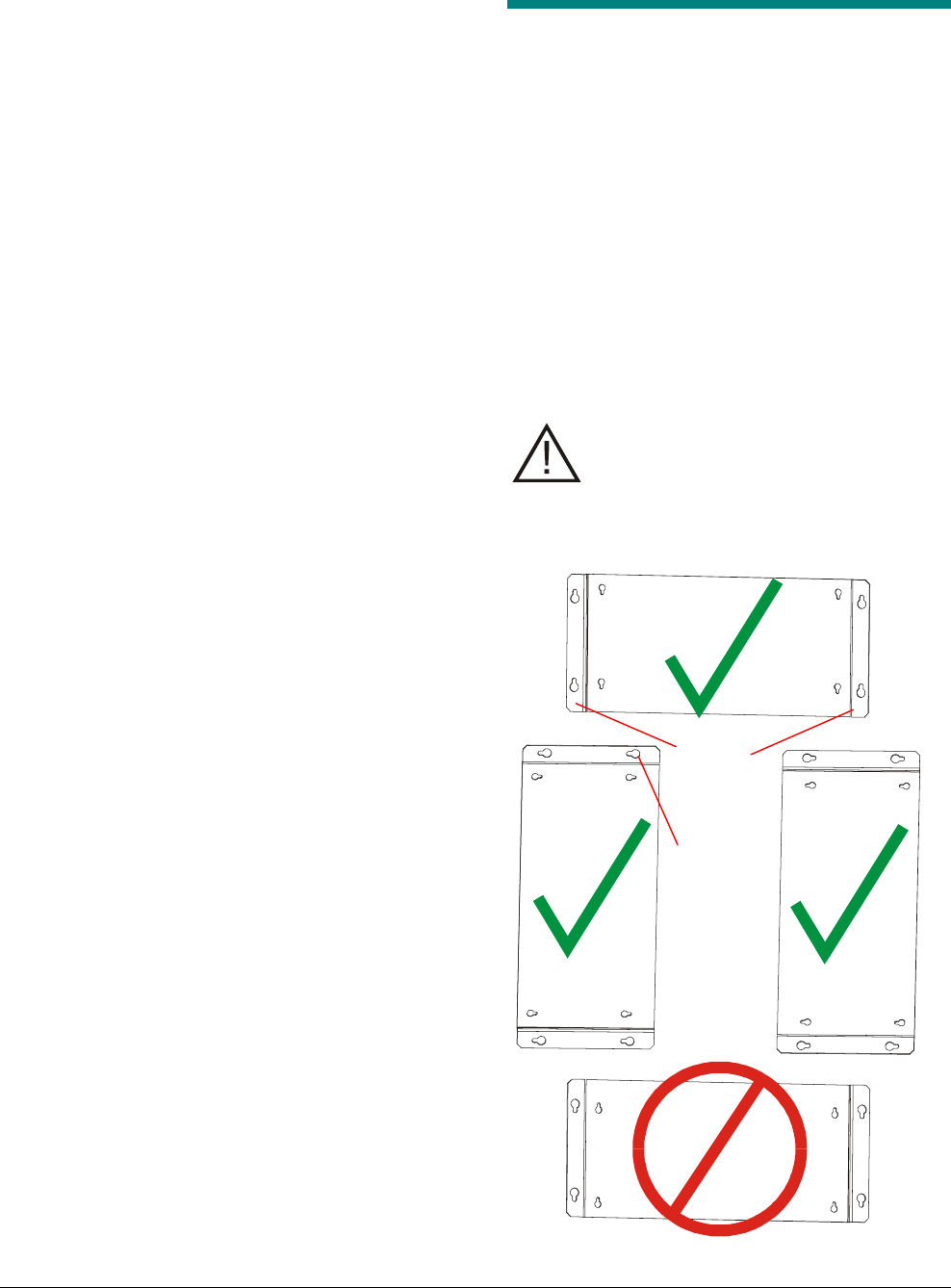
To mount the controller to a wall:
1. Using the mounting bracket as a template,
mark four holes on the wall.
CAUTION: The mounting bracket can be
oriented vertically or horizontally, but it
must not be mounted with the keyholes
on the flanges upside, down as shown
below.
Keyhole
Flanges
Preliminary
AMS-9030 CONTROLLER 8200-0344-02, REV. 0
INSTALLATION GUIDE 4 of 16
2. Drill holes into the wall and insert anchors.
Note: The mounting method must be able to
support 23.5 kg (52 lbs).
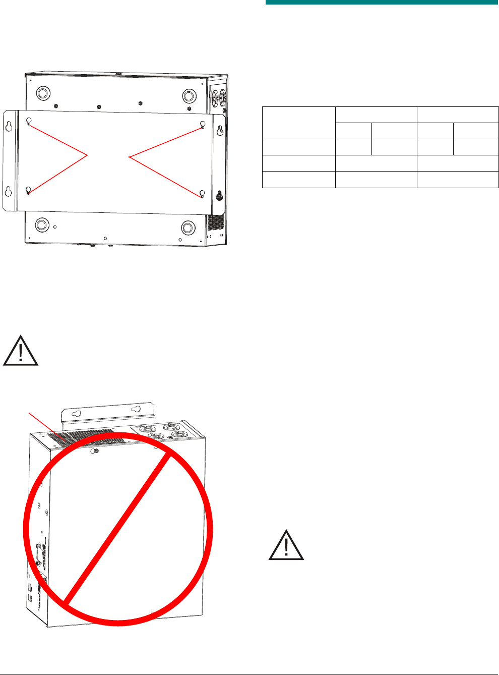
3. Secure the mounting bracket to the controller
using the four screws provided.
4. Secure the mounting bracket to the wall. The
preferred orientations for the controller are with
the fan on the bottom or on the left side. It is
acceptable to mount the controller with the fan
on the right side.
CAUTION: Do not mount the controller
with the fan on top as shown in Figure 2.
Figure 2. Prohibited controller orientation
Connecting Antennas
Currently you can only connect Ultra*Post Plus-
compatible antennas to the AMS-9030 controller.
The controller contains some connectors reserved
for future antennas. The table below shows where
you connect the cables. Figure 5 shows the
locations of the connectors.
Antenna A Antenna B
Plus Future Plus Future
Comm P15 P14 P18 P17
Transceiver P13 P16
Receive only P22 P23
Rules
The controller has two transmit channels (A and B)
and two receive channels (A and B). Observe the
following rules when connecting antennas to these
channels.
• The controller cannot transmit simultaneously
on both the A and B channels. It can transmit
on only the A or B channel or alternately on
both.
• The controller receives on both the A and B
channels simultaneously, even if it is only
transmitting on one channel.
• Pulling jumpers P25-P28 enables connectors
P22 and P23 as receive only and configures
P13 and P16 as transmit only. Jumpers P25
and P26 control the reception of the Antenna A
connector (P13 and P22) and jumpers P27 and
P28 control the reception of the Antenna B
connectors (P16 and P23).
• Before removing the knockouts in the controller
for the antenna cables, unscrew the knockout
plate from the controller to avoid bending the
tabs on the plate.
CAUTION: Bridging alarm signals
between two Comm ports (P15 and P18
or P14 and P17) will damage the
controller. This was done on some
Ultra*Post Plus controllers when an
antenna without a built-in alarm (for
example, Rangers) was used. Instead,
use the configurator to cause alarms on
one channel to activate the alarm on the
other channel.
Fan
Screws
Preliminary
AMS-9030 CONTROLLER 8200-0344-02, REV. 0
INSTALLATION GUIDE 5 of 16
CAUTION: Do not connect ferrite
receivers (for example, Rangers, Satellite
receivers) to the transceiver connectors
P13 and P16. They must only be
connected to receiver ports P22 and P23.
CAUTION: Do not plug antennas into
controller while the controller is on. Doing
so can damage the power amplifier or
power supply chip in the controller.
WARNING: RISK OF ELECTRIC
SHOCK! Do not adjust tuning jumpers
while controller is on. Doing so can
expose you to ac voltage and damage
the controller.
Connecting to P15 and P18
Connectors P15 and P18 are the Communication
connectors for antennas compatible with Ultra*Post
Plus antennas. Ultra*Post compatible antennas
can be divided into three categories: those with
12V alarm lamps, those with 5V alarm lamps, and
antennas without alarm lamps. The tables below
list the antennas that are compatible with the AMS-
9030 and which type of antenna they are.
Table 1. +12V Lamp antennas
ZSDDM DoorMax Antenna
Table 2. +5V Lamp antennas
ZSEMPLUS EuroMax Plus Pedestals
ZSEPPLUS MegaMax Plus Pedestal
ZSDPMPLUS Digital Pro-Max Plus
Pedestal
Table 3. No alarm lamp antennas
ZAUPSH2 Ultra*Post Non-Alarming,
Non-European
ZSDFMPLUS2-A AMS-2001 (FloorMax) (12m)
ZSDFMPLUS2-A18 AMS-2001 (FloorMax) (18m)
ZSLOOP-2E Loop antenna Kit
The following two tables show how to connect the
+5V and +12V antennas; antennas without alarms
do not connect to P15 and P18. Note that
depending on how the controller motherboard has
been configured, pin 3 provides either +5v or +12V
for the antenna alarm lamp.
Table 4. +5V style pinouts
Pin Signal Wire Color
1 Audio + Orange
2 Audio Return Red
3 +5V Lamp Yellow
5 Ground Grey
10 Shield Shield
Table 5. +12V style pinouts
Pin Signal Wire Color
1 Audio + Black
2 Audio Return Brown
3 +12V Lamp Red
4 Not used Orange
5 Ground Yellow
6 Ant. A RS232 Rx Green
7 Ant. A RS232 Tx Blue
8 Not Used Violet
9 +15V Gray
10 Shield Shield

Preliminary
AMS-9030 CONTROLLER 8200-0344-02, REV. 0
INSTALLATION GUIDE 6 of 16
Configurations
The following list describes the basic ways that
antennas can be configured with the controller.
Figure 3 and Figure 4 show examples of these
configurations.
• Single – one transceiver (XCVR) antenna
connects to P13 (A) or P16 (B).
• Single with one receiver – the transmitting
antenna can be configured as a transceiver or a
transmitter. If it is configured as a transceiver
and it connects to P13 (A), then the receiver
connects to the opposite receive-only channel,
P23 (B). If the antenna is configured as a
transmitter only, it connects to P13 (A), a
receive-only antenna connects to P22 (A), and
jumpers 25 and 26 (A) must be removed.
• Single with two receivers – one transmit-only
antenna connects to P13 (A) or P16 (B). Two
receive-only antennas are both connected to
P22 (A) or P23 (B). Jumpers 25 and 26 (A) or
27 and 28 (B) must be removed.
• Dual – two transceiver antennas connect to
P13 and P16.
• Dual with two receivers – Two transmit-only
antennas are connected to P13 and P16. Two
receive-only antennas are connected to P22
and P23. Jumpers 25-28 must be removed.
• Split Tx Rx Tx – Two transmit-only antennas
are connected to P13 and P16. One receive-
only antenna is connected to P22 or P23, but
you must wire P22 to P23. Jumpers 25-28 must
be removed.
• Split (also called Triple) – a two-controller
system with three antennas. Two transceiver
antennas are connected to P13 and P16 on one
controller and one transceiver antenna is
connected to P13 on another controller. If the
antennas are near each other, a wired sync
cable is required.
• Triple with three receivers – a two-controller
system with three antennas. One controller has
two transmit-only antennas connected to P13
and P16 and two receive-only antennas
connected at P22 and P23. Jumpers 25-28
must be removed on this controller. The other
controller has one transmit-only antenna
connected at P13 and one receive-only antenna
connected to P22. Jumpers 25 and 26 must be
removed on this controller. If the antennas are
near each other, a wired sync cable is required.
• Quad – a two-controller system with four
antennas. Both controllers have two transceiver
antennas connected to P13 and P16. If the
antennas are near each other, a wired sync
cable is required.
Preliminary
AMS-9030 CONTROLLER 8200-0344-02, REV. 0
INSTALLATION GUIDE 7 of 16
Figure 3. Single and dual antenna configurations
Single Single with one receiver Single with two receivers
Dual Dual with two receivers
Transceive
r
(XCVR)
Tx Rx Rx Rx Tx
XCVR XCVR Tx Tx
Rx Rx
XCVR Rx
Preliminary
AMS-9030 CONTROLLER 8200-0344-02, REV. 0
INSTALLATION GUIDE 8 of 16
Figure 4. Split, triple, and quad antenna configurations
Split Tx Rx Tx Split (or Triple)
Triple with three receivers Quad
XCVR Tx XCVR XCVR Tx Rx
Tx Tx
Rx Rx
XCVR
Rx
XCVR XCVR XCVR XCVR
Preliminary
AMS-9030 CONTROLLER 8200-0344-02, REV. 0
INSTALLATION GUIDE 9 of 16
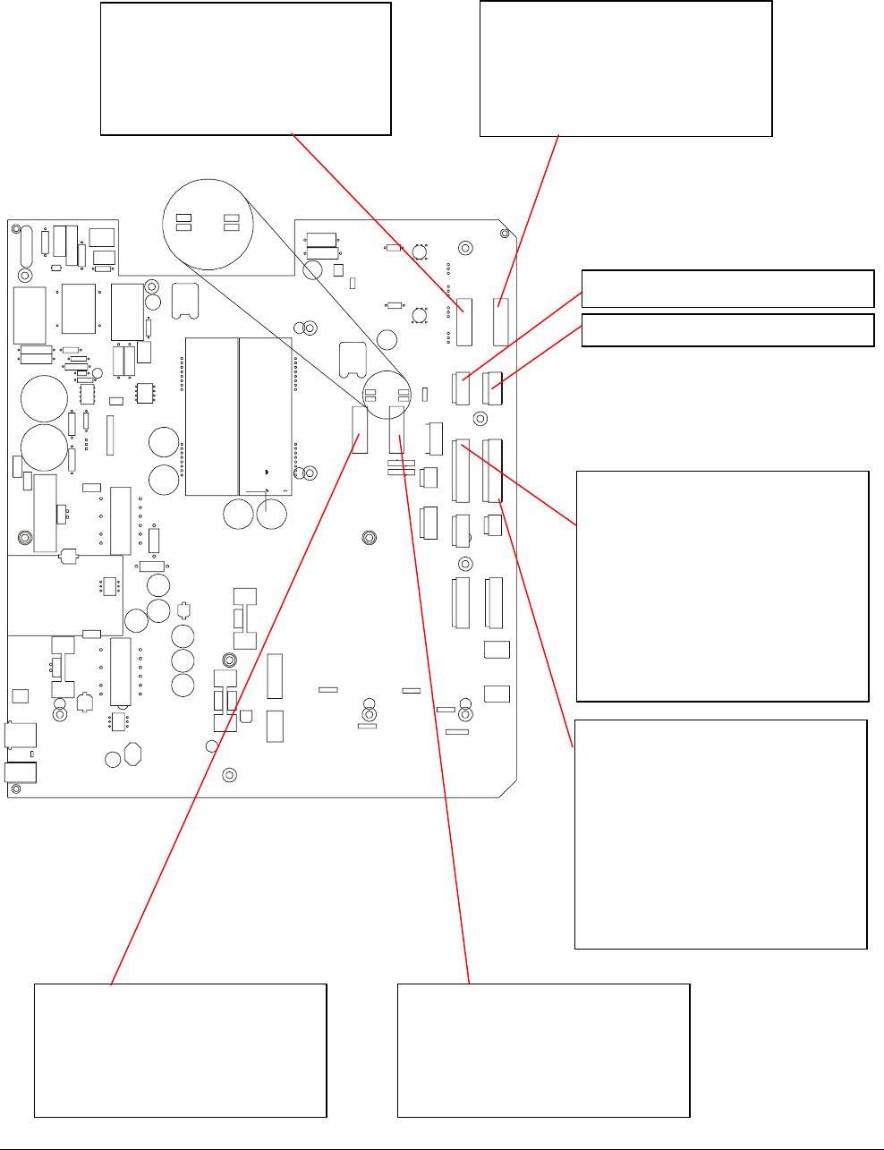
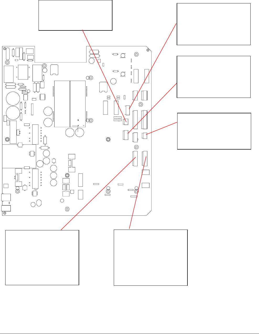
Figure 5. Controller antenna pinouts
P13 Pedestal A XCVR
P14 Pedestal A Com - 9040
P15 Pedestal A Com - Plus
P16 Pedestal B XCVR
P17 Pedestal B Com - 9040
P18 Pedestal B Com - Plus
P22 Pedestal A Rx only
1 Ground
2 RS485 B Low
3 RS485 B High
4 +15V Alarm
5 Shield
1 Ground
2 RS485 A Low
3 RS485 A High
4 +15V Alarm
5 Shield
1 Antenna A Audio +
2 Antenna A Audio Return
3 Antenna A +5V/12V Lamp
4 RS485 A Low
5 Ground
6 Antenna A RS232 Receive
7 Antenna A RS232 Transmit
8 RS485 A High
9 +15V
10 Shield
1 Antenna A Bottom
2 Antenna A Bottom Return
3 Antenna A Top Return
4 Antenna A Top
5 Shield
1 A Bottom Receive
2 A Bottom Receive Return
3 A Top Receive Return
4 A Top Receive
5 Shield
1 Antenna B Bottom
2 Antenna B Bottom Return
3 Antenna B Top Return
4 Antenna B Top
5 Shield
1 Antenna B Audio +
2 Antenna B Audio Return
3 Antenna B +5V/12V Lamp
4 RS485 B Low
5 Ground
6 Antenna B RS232 Receive
7 Antenna B RS232 Transmit
8 RS485 B High
9 +15V
10 Shield
P23 Pedestal B Rx only
P25
P26
P27
P28
Reserved for future use
Reserved for future use
1 B Bottom Receive
2 B Bottom Receive Return
3 B Top Receive Return
4 B Top Receive
5 Shield
Preliminary
AMS-9030 CONTROLLER 8200-0344-02, REV. 0
INSTALLATION GUIDE 10 of 16
Figure 6. Controller device pinouts
P19 Pedestal A Relay
1 Relay A1 Arm
2 Relay A1 Normally Closed
3 Relay A1 Normally Open
4 Shield
5 Relay A2 Arm
6 Relay A2 Normally Closed
7 Relay A2 Normally Open
8 Shield
P20 Pedestal B Relay
1 Relay B1 Arm
2 Relay B1 Normally Closed
3 Relay B1 Normally Open
4 Shield
5 Relay B2 Arm
6 Relay B2 Normally Closed
7 Relay B2 Normally Open
8 Shield
P29 Alarm
1 +15V
2 Ground
3 Remote Alarm
4 Not Used
5 Shield
P3 RS-485
1 RS485 Low
2 RS485 High
3 Ground
P9 Controller Sync
1 Sync
2 Ground
3 Shield
P21 Noise Coil A and B
1 Noise/Rx Coil A
2 Noise/Rx Coil A Return
3 Noise/Rx Coil B Return
4 Noise/Rx Coil B
5 Shield
Preliminary
AMS-9030 CONTROLLER 8200-0344-02, REV. 0
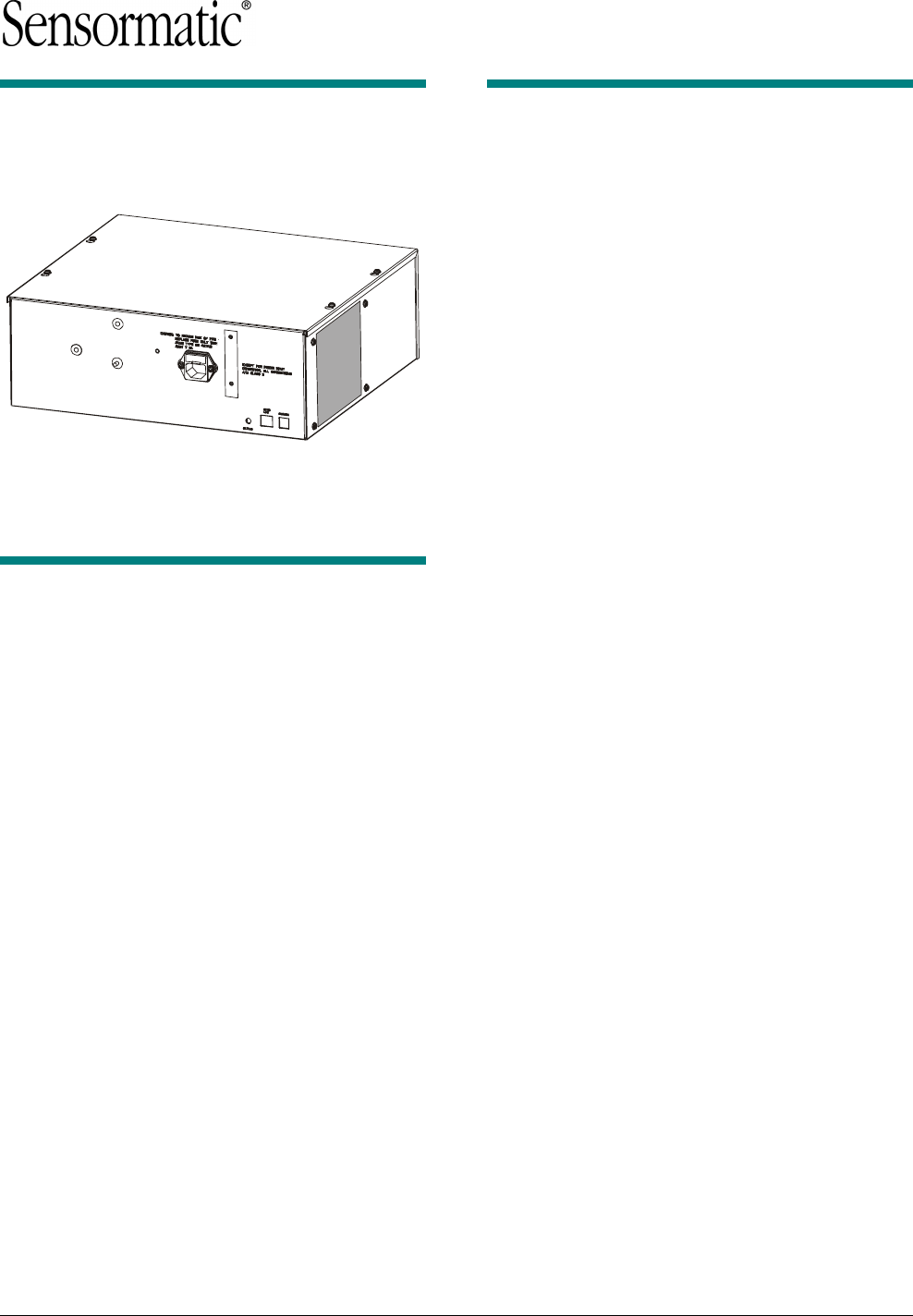
INSTALLATION GUIDE 11 of 16
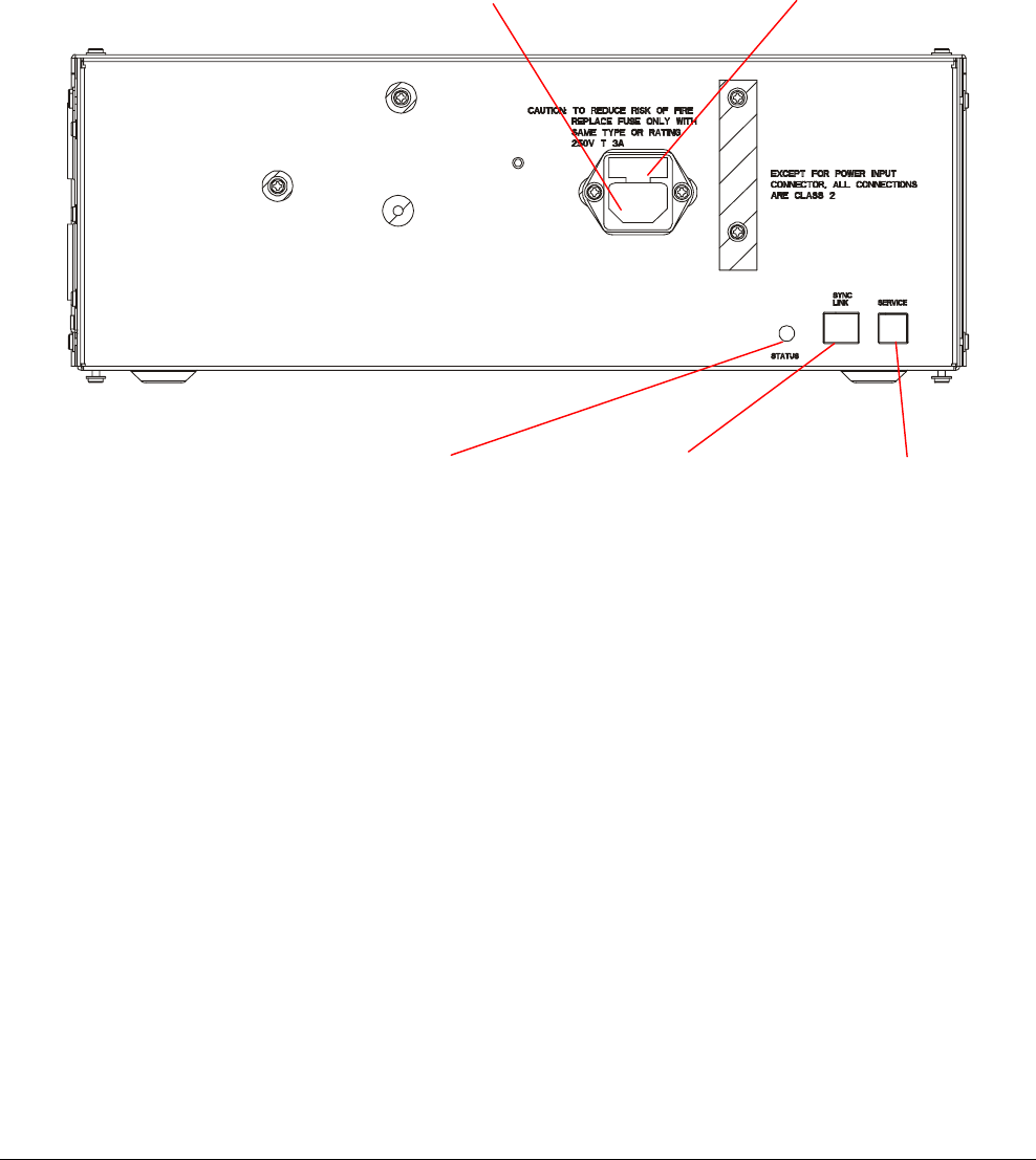
Figure 7. Front of controller
IEC320 Power connector Fuse holder
SyncLink port Service port Status LED
Preliminary
AMS-9030 CONTROLLER 8200-0344-02, REV. 0
INSTALLATION GUIDE 12 of 16
Connecting Remote Alarms
The AMS-9030 controller provides the power and
control signals for a single remote alarm (ZC30-
ADS/ZC35-ADS) at P29. (This is the only powered
alarm port.) This remote alarm will sound whenever
a tag or label is detected at either antenna; it will
not provide zone detection.
Note: If you have the controller supporting two
exits and you want to connect two independent
alarms so that antenna A will control one alarm and
antenna B will control the other alarm (zone
detection), you need to connect the remote alarms
to the relays at P19 and P20 instead. Refer to the
section “Connecting External Devices to Controller
Relays” on page 12.
1. Ensure the remote alarm is ADS compatible.
ADS compatible alarms are marked with a
sticker on the box. If the remote alarm is not
ADS compatible, remove resistor R5 from the
main alarm board (0301-0241-01) of the remote
alarm before installing.
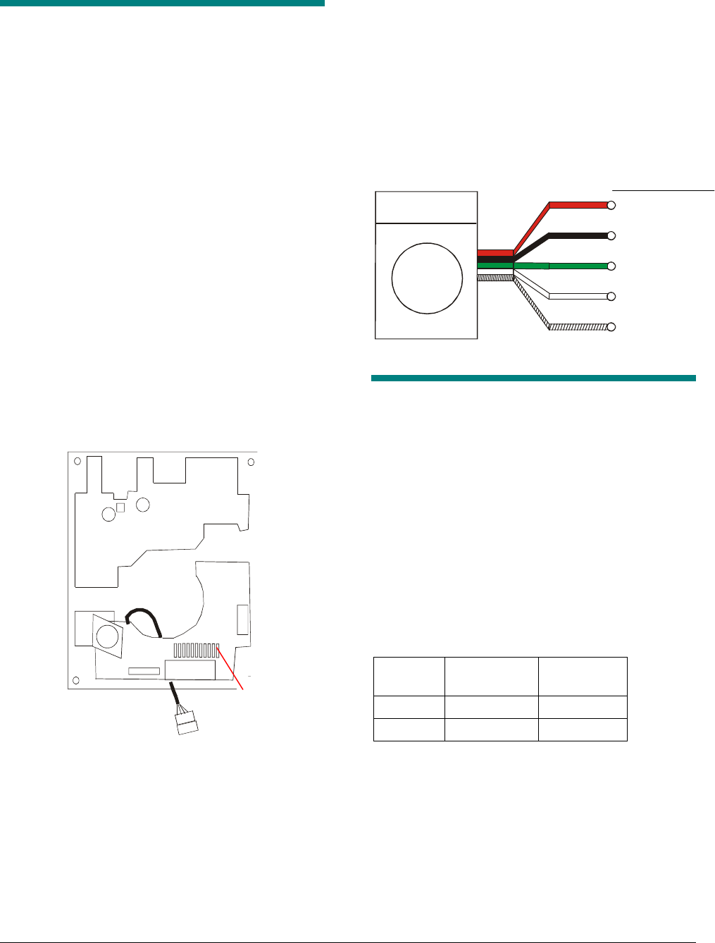
Figure 8. Location of R5 resistor
2. Connect the remote alarm to the Remote Alarm
connector (P29) on the controller. Figure 6
shows the location of P29 and Figure 9 shows
how to connect the remote alarm. Note that the
black and red wires are connected to different
pins than other controllers.
Figure 9. Connecting a remote alarm to P29
Connecting External Devices
to Controller Relays
The AMS-9030 controller has two internal relays (A
and B) to which you can connect an external
device, such as a remote alarm. Each relay can
control two devices. The controller provides a
contact closure only; the external device must
supply its own power.
The relays are activated when the system alarms.
The relays are double-pole double-throw (DPDT),
which means relay A is activated only when
antenna A alarms and relay B is activated only
when antenna B alarms. The table below shows
which relay is activated by which antenna.
Antenna Antenna
Connector
Relay
Connector
A P13, P15 P19
B P16, P18 P20
Figure 6 shows the location of the P19 and P20
connectors and their pinouts.
1. Connect the green, white, and silver wires of
the two remote alarms to Relays A and B (P19
and P20). Refer to Figure 10, Table 1, and
Table 2.
2. Connect black and red wires to the transformer.
R5 resisto
r
Remote alarm
(ZC30/ZC35)
red
green
1 +15V
4
(
N.O.
)
black
white
3
(
Arm
)
2 Ground
P29
shield
5
(
Shield
)
Pin Signal
Preliminary
AMS-9030 CONTROLLER 8200-0344-02, REV. 0
INSTALLATION GUIDE 13 of 16
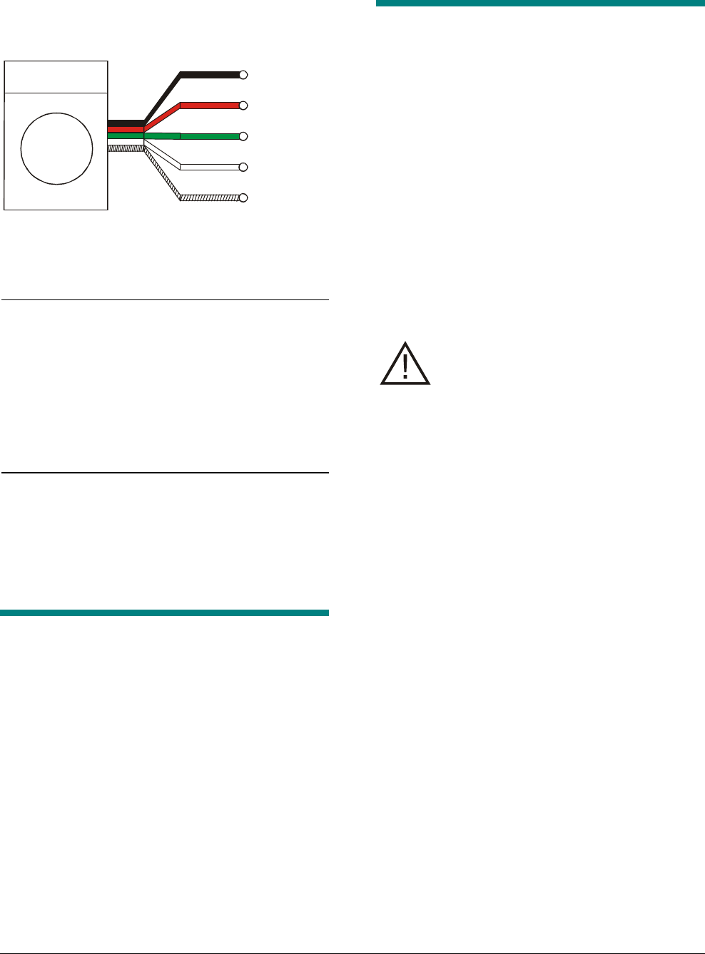
Figure 10. Connecting a remote alarm to P20
Table 6. Connecting remote alarm A
Alarm Wire Connector Pin Signal
Black Com 1 V Alarm Ret
Red 17V 2 +V Alarm
Green P19 1 A - Arm
White P19 2 A – N.O.
Silver P19 5 Ground
Table 7. Connecting remote alarm B
Alarm Wire Connector Pin Signal
Black Com 1 V Alarm Ret
Red 17V 2 +V Alarm
Green P20 3 B - Arm
White P20 4 B – N.O.
Silver P20 5 Ground
Connecting Noise Canceling
Antennas
You can connect one set of noise canceling
antennas to the AMS-9030 controller. You can use
either the Ranger antennas (ZKNC-R) or the
Skymax antennas (ZKNC-SM). You connect the
noise canceling antennas at connector P21 on the
controller. Figure 6 shows the location of the
connector and its pinout.
Connecting Multiple 9030
Controllers
If you install adjacent (within 1.1m (3.5’)) antennas
attached to different controllers, the energy from
one antenna can couple with the other and
produce an over-current situation. The system will
then shut down periodically for ten seconds and log
an error. To prevent this, multiple controllers
attached to adjacent antennas must be wired
together to synchronize their transmissions.
In wired synchronization, one controller is
designated as the master and the others as slaves.
The master controller uses the P9 connector to
send a synchronization signal to the P9 connector
on the slave controllers. The procedure for
installing wired synchronization follows.
CAUTION: If any controller goes off,
wired sync does not work for any slave
controller in the sequence. Disconnect
wired sync before powering off a
controller.
1. Route two 0.35mm (22 AWG) or heavier wires
from the master controller to each slave
controller.
The maximum distance between the master and
any slave for 22 AWG wire is 25m (80’). If the
distance between controllers is greater than
25m (80’), consult Tech Support for the proper
wire gauge.
2. Connect the two wires to each master and slave
controller as shown in Figure 11.
3. Turn on the controllers.
4. Use the configurator to set the Setup screen
parameters in the controllers to the following
values.
• Antenna Type – This parameter should be
set to Transceiver, even if only one
antenna is connected to the controller. A
single antenna should be set to
Transceiver so that its transmit rep rate will
match the rep rate of the adjacent antenna.
• Auto-Detection – This parameter should
be set to Off. Otherwise, if the site has a
power outage, the controller will reboot and
won’t set single antennas to Transceiver
Type.
Remote alarm
(ZC30/ZC35)
black
green
COM
N.O.
red
white
Arm
17V
silve
r
Ground}
}Trans
former
P19/
P20
Preliminary
AMS-9030 CONTROLLER 8200-0344-02, REV. 0
INSTALLATION GUIDE 14 of 16
Figure 11. Wired sync wiring diagram
1
2
3
1
2
3
5. Use the configurator to set the Advanced
Settings parameters in the controllers to the
following values.
Wired synchronization Advanced Settings
parameters
Parameter Master Slave
Wired Sync Enable Enabled Enabled
Wired Sync Master Enabled Disabled
6. Check the status LED on the slave controllers.
If the LED is flashing amber twice as fast as
normal (two times per second), then the slave is
not receiving a synchronization signal and you
must recheck the installation or the software
setup.
Connecting a Service
Laptop
To use the configurator on your service laptop to
configure the controller, connect your laptop to the
female RJ22 port labeled “Service” on the
controller. See Figure 7.
You can also connect a service laptop remotely
over a network. For information on connecting a
laptop remotely, refer to the Setup and Service
Guide.
In addition to the controller, some antennas have a
service port to which you can connect a service
laptop.
Figure 12. Connecting a local service laptop
Connecting a SyncLink
Device
SyncLink devices connect to the controller at the
SyncLink port on the controller. The location and
pinout of the SyncLink port is shown in Figure 7.
Sync signal
Ground
Shield
P9
P9
Master Controller
Slave Controller
Sync signal
Ground
Shield
RJ22 male connector
RJ11 male
connecto
r
RJ11 male to RJ22
male cable
DB-9-to-RJ11
adapter
laptop DB-9 serial port
service port (RJ22 female)

Preliminary
AMS-9030 CONTROLLER 8200-0344-02, REV. 0
INSTALLATION GUIDE 15 of 16
Connecting an Ultra*Link
Device
Ultra*Link devices are connected to the controller
at the Service port on the controller and at the
COMM1 port on the Ultra*Link device. The location
and pinout of the Service port is shown in Figure 1.
Note: if the controller has an Ultra*Link device on
its Service port, it cannot communicate with a
laptop connected there or on an antenna.
Connecting Power to the
Controller
The standard controller receives power through a
power cord that is plugged into the IEC320
connector shown in Figure 7.
One power switching options is available for the
controller: a keyswitch option. This option must be
hardwired to a power source. Refer to the
installation manual for this option for more
information.
After connecting the controller to ac power, check
the status light (Figure 7) to make sure it is flashing
green once a second. If it is flashing two times a
second or it is red, it indicates a problem with the
system.
WARNING: RISK OF ELECTRIC
SHOCK! Ensure power is turned off at
circuit breaker before hardwiring
controller.
Specifications
Electrical
Power Supply
Primary Input .................................... 100-130Vac or
200-240Vac
@ 50–60Hz
Primary Power Fuse............................... 2.5A, 250V
Current Draw ............................1.2A peak (120Vac)
0.8A peak (230Vac)
Input Power .................................................. <150W
Transmitter
Outputs................................. 2 ports (two antennas,
multiplexed)
Operating Frequency .....................58kHz (±200Hz)
Transmit Burst Duration .................................1.6ms
Transmit Current ........................................ 8A peak
Burst Repetition Rate:
Based on 50Hz ac ................. 37.5Hz (Normal)
75Hz (Validation)
Based on 60Hz ac .................... 45Hz (Normal)
90Hz (Validation)
Receiver
Inputs.................................... 2 ports (two antennas,
multiplexed)
Center Frequency ..........................................58kHz
Alarm
Alarm Relay Output ......................... DPDT contacts
Contact Switching Current ...................... 1.0A max.
Contact Switching Voltage ....................... 28V max.
Lamp/Audio Duration ............................... 1–30 sec.
(1 sec. increments)
Environmental
Operating Temperature:...0° to 50°C (32° to 122°F)
(32° to 122°F)
Non-operating Temperature................. -40° to 70°C
(-40° to 158°F)
Relative Humidity: ........... 0 to 90% non-condensing
Preliminary
AMS-9030 CONTROLLER 8200-0344-02, REV. 0
INSTALLATION GUIDE 16 of 16
Mechanical
Controller
Length ...............................................36.8cm (14.5")
Width.................................................32.8cm (12.9")
Depth .....................................................13cm (5.1")
Weight.......................................... 5.85kg (12.9 lbs.)
Remote Alarm / Message Unit
Height ....................................................20.3cm (8")
Length ....................................................15cm (5.9")
Width.....................................................6.4cm (2.5")
Declarations
Regulatory Product names
The following products are referenced in this manual.
Product name Prod. Code Regulatory ID
AMS-9030 controller ZE9030 AMS-9030
Remote alarm ZC30/ZC35 MC76
Ranger antenna ZKNC-R UM UPFAF
Sky-Max antenna ZKNC-SM UM SKYMAX
Regulatory Compliance
EMC ............................................... 47 CFR, Part 15
EN 300 330
EN 301 489
RSS 210
Safety........................................................UL 60950
CSA C22.2 No 60950
EN 60950
FCC COMPLIANCE: This equipment complies with Part 15
of the FCC rules for intentional radiators and Class A digital
devices when installed and used in accordance with the
instruction manual. Following these rules provides reasonable
protection against harmful interference from equipment
operated in a commercial area. This equipment should not be
installed in a residential area as it can radiate radio frequency
energy that could interfere with radio communications, a
situation the user would have to fix at their own expense.
EQUIPMENT MODIFICATION CAUTION: Equipment
changes or modifications not expressly approved by
Sensormatic Electronics Corporation, the party responsible for
FCC compliance, could void the user's authority to operate the
equipment and could create a hazardous condition.
Other Declarations
WARRANTY DISCLAIMER: Sensormatic Electronics
Corporation makes no representation or warranty with respect
to the contents hereof and specifically disclaims any implied
warranties of merchantability or fitness for any particular
purpose. Further, Sensormatic Electronics Corporation
reserves the right to revise this publication and make changes
from time to time in the content hereof without obligation of
Sensormatic Electronics Corporation to notify any person of
such revision or changes.
LIMITED RIGHTS NOTICE: For units of the Department
of Defense, all documentation and manuals were developed at
private expense and no part of it was developed using
Government Funds. The restrictions governing the use and
disclosure of technical data marked with this legend are set
forth in the definition of “limited rights” in paragraph (a) (15)
of the clause of DFARS 252.227.7013. Unpublished - rights
reserved under the Copyright Laws of the United States.
TRADEMARK NOTICE: Sensormatic is a registered
trademark of Sensormatic Electronics Corporation. Other
product names mentioned herein may be trademarks or
registered trademarks of Sensormatic or other companies.
No part of this guide may be reproduced in any form without
written permission from Sensormatic Electronics Corporation.
RWH 11/03