Tyco Safety Sensormatic AMS9040 anti theft device User Manual New Name
Tyco Safety Products/Sensormatic anti theft device New Name
users manual
Company Confidential
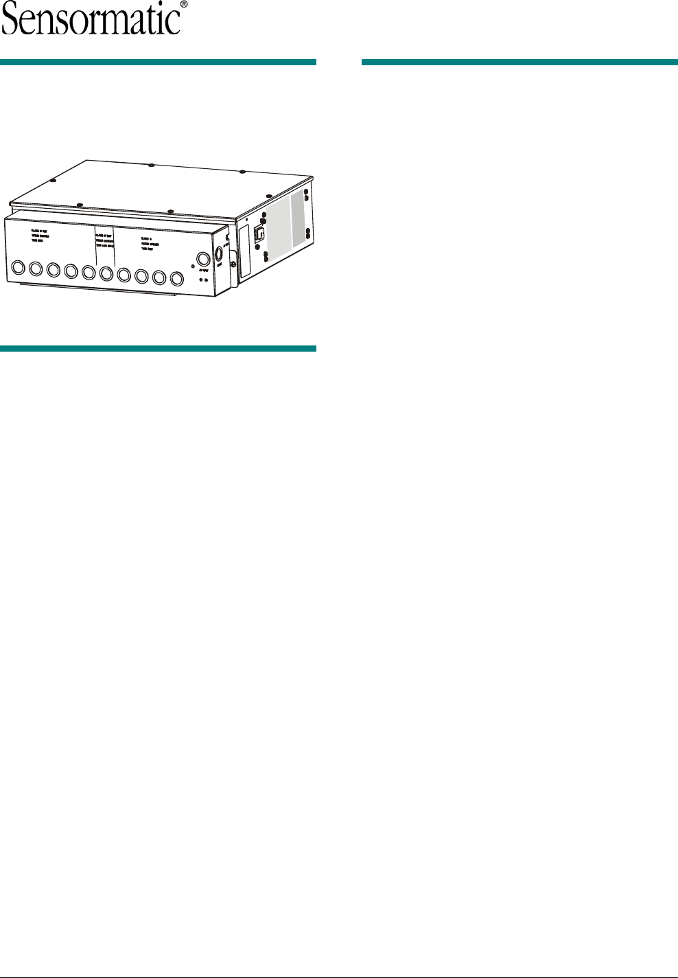
AMS-9040 Controller
Installation and Service Guide
Contents
To the Installer....................................................... 1
About the Product.................................................. 2
Operation ........................................................... 2
Device Connections ........................................... 3
Installation Features........................................... 7
Service Features................................................ 8
Installation ............................................................. 9
Installation Requirements .................................. 9
Installation Procedure ...................................... 10
Power Connections.......................................... 13
Sample Hookups.............................................. 14
Troubleshooting................................................... 15
System Status Alert Codes .............................. 15
Laptop/Modem Connections............................ 16
Fuse Replacement........................................... 17
Specifications ...................................................... 18
Declarations ........................................................ 18
Appendix A: About Auto Sync ........................... 19
© 2004 Sensormatic
To the Installer
This installation and service guide explains how to
install, setup, and service the AMS-9040 controller.
Parts required to install this system are:
- AMS-9040 Controller (ZEAISLEPP)
- Digital AM antennas (various)
- Extension bracket 0500-9792-01 (optional)
- AMS-9040 Controller Keyswitch (optional)
Other documents that may be required for
installation are:
- Planning Guide, 8200-0367-01
- Antenna Installation Guide (various)
- Antenna Controller Keyswitch, 8200-0367-04
Note:
- Because customer requirements dictate the
placement of system components, your
Sensormatic representative will supply this
information separately.
- If this product was installed in a European
Union or European Free Trade Association
member state, please give the Declaration of
Conformity included with this product to the
manager or user. By law, this information must
be provided to the user.
- There may be restrictions on the installation of
certain antennas in certain countries. Please
see the antenna installation guides for
documentation of the restriction.
AMS-9040 CONTROLLER 8200-0367-02, REV. 9
INSTALLATION AND SERVICE GUIDE 1 of 20
Company Confidential
About the Product
The AMS-9040 controller is part of a
four-channel EAS detector used to detect EAS
tags/labels at store exit(s). The controller:
- Supports transceiver (Tx/Rx) antennas, auxiliary
receiver antennas, and noise coils in any
combination up to the maximum specified.
- Supports controller-assisted tuning of Digital AM
antennas.
- Can power and control up to two remote alarms.
Also supports externally powered alarm devices
and beacon lamps, an alarm management
device, and a Sensormatic Sync Link wireless
sync device.
- Has four relays used to trigger externally-
powered alarm devices.
- Supports RS485 networking.
- Has connections for hardwired sync and
transmit inhibit functions.
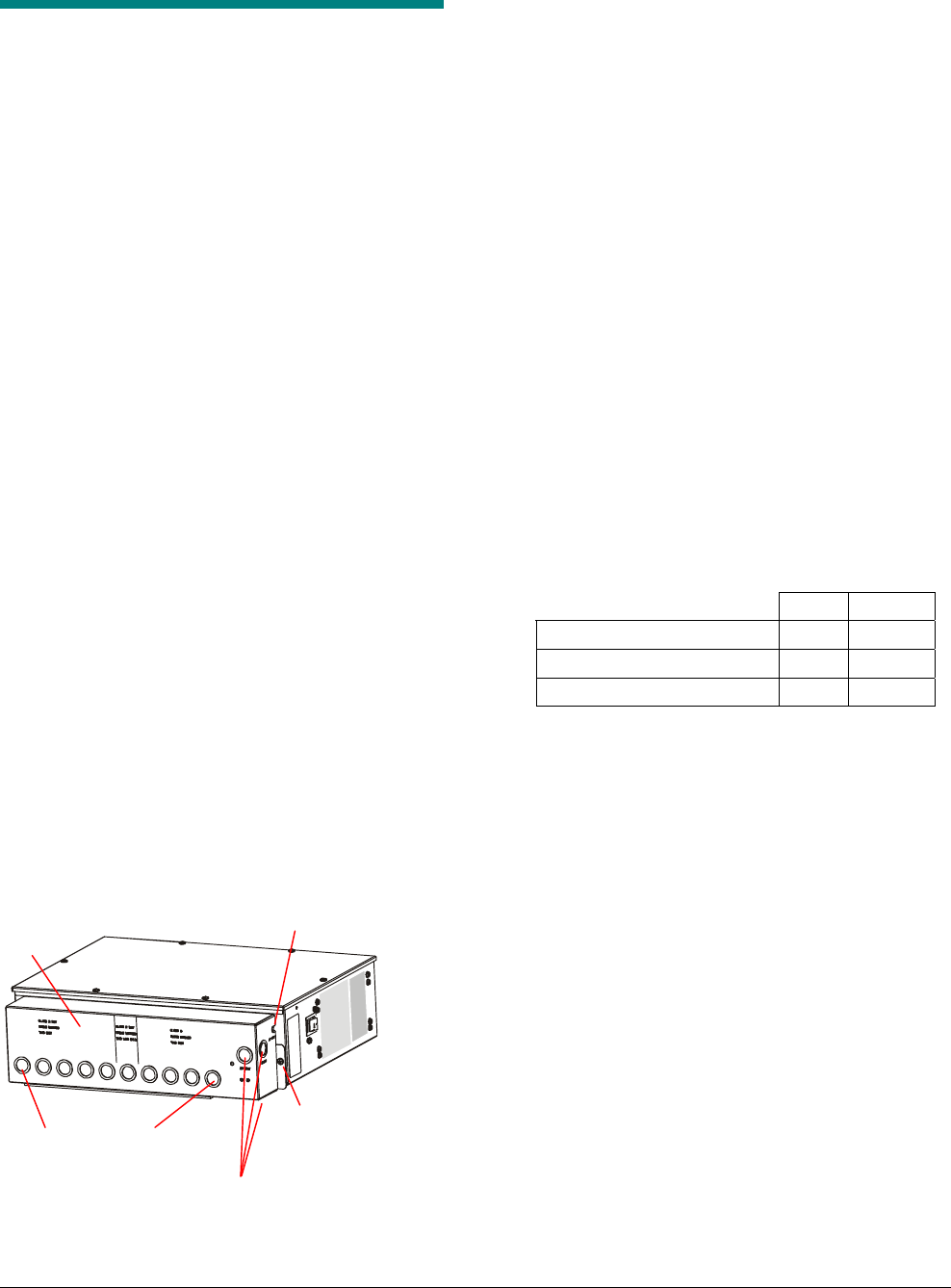
- Can be placed on a shelf or mounted to a wall.
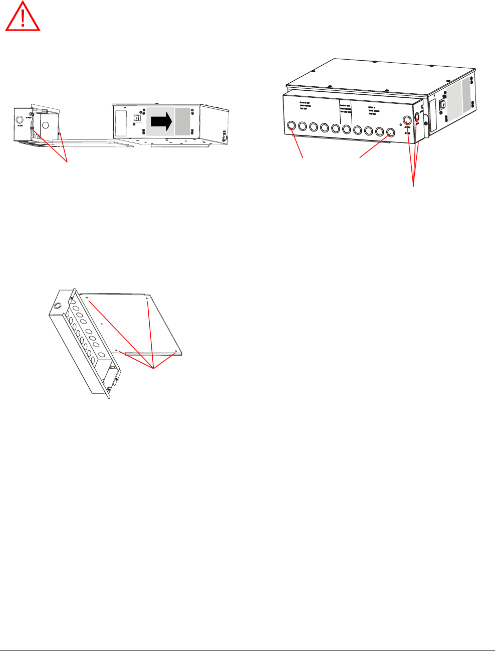
- Consists of an integral cable tray/mounting
bracket assembly and a controller housing that
attaches to it. Two captive ¼-turn fasteners in
the tray secure it to the controller.
- Nineteen knockouts in the cable tray support
exposed cables or cables in conduit. There are
designated knockouts for Class 2 wiring from
low voltage devices, Class 2 “wet” wiring from
an alarm management device, and Class 3
wiring from a transmit antenna.
- Three knockouts in the tray support an exposed
ac cable or the cable in conduit. A U-shaped
opening in the side of the tray allows access for
a power cord, if used instead of the ac cable.
Operation
The controller deters theft by activating an alarm
when it detects the unique response of an active
Ultra•Max hard plastic tag or disposable label.
To detect a tag, the antenna(s) connected to the
controller emit a magnetic field close to the
tag/label’s natural frequency causing it to vibrate or
“ring” at the frequency of the field. When the field is
removed, energy in the tag/label dissipates causing
an exponential ring down.
The controller processes signal inputs picked up by
the antennas to determine if they are indicative of
ring down. If they are, then the controller activates
an alarm.
Audible and visual indicators located on top of
each antenna indicate an active tag/label is
between the antennas. Alternately, the controller
can trigger a remote alarm module, or double-pole
double-throw relay, one for each antenna. The
controller can also trigger externally powered
devices such as a security camera.
- Antenna coils can be set to aiding or figure-8.
Maximum operating current is as follows for
each coil configuration:
Aiding Figure 8
Non-European 16A 16A
European (except Germany) N/A 12A
Germany N/A 10A
- Maximum cable length between antennas and
controller is 15.2m (50ft). Longer cables can
reduce performance and operating current.
3 knockouts for hardwired AC
(1 on underside)
Tray to controller
captive ¼-turn fastener
(
one at each end
)
Cable Tray
19 knockouts for cables
(1 on side, 8 on underside)
U-shaped opening for power cord
AMS-9040 CONTROLLER 8200-0367-02, REV. 9
INSTALLATION AND SERVICE GUIDE 2 of 20

Company Confidential
Device Connections
Connector pin assignments are listed on pages 4
and 5. Device connections are as follows:
- Transceiver antenna connections (4) and
antenna communication connections (4)
- General-purpose connections (4) for auxiliary
receive antennas and/or noise coils*
- Remote alarm connections (2)
- Beacon lamp connections (2)
- Relay connections (4)
- Alarm management device connection (1)
- RS485 connection (1)
- Wired Tx sync connection (1)
- Tx inhibit connection (1)
- Wireless ac synchronization (Sync Link)
connection (1)
- Service connection (1).
* Only certain inputs support noise coils.
Transceiver (Tx/Rx) Antenna and
Antenna Communication Connections
Transceiver antenna connectors and antenna
communication connectors support the following
transceiver antennas and families:
- Digital Door-Max*
- Digital Floor-Max*
- Digital Pro-Max*
- Digital Euro Pro-Max*
- Ultra•Loop
* Controller-assisted tuning applies. See page 7.
Transceiver connectors (P1, P24, P4, P35). Four
connectors support transceiver antennas
designated A, B, C, and D.
- Tx/Rx antenna A connects to connector P1.
- Tx/Rx antenna B connects to connector P24.
- Tx/Rx antenna C connects to connector P4.
- Tx/Rx antenna D connects to connector P35.
Antenna communication connectors (P5, P25,
P6, P36). Four connectors support controller-
assisted tuning of digital antennas.
- Com for antenna A connects to connector P5.
- Com for antenna B connects to connector P25.
- Com for antenna C connects to connector P6.
- Com for antenna D connects to connector P36.
General-Purpose Connections
(P27, P29, P31, P33)
Four connectors accept auxiliary receive antennas
such as Rangers, Digital Pro-Max, Sky•Max, and
Satellite receivers, and/or noise coils up to the
maximum allowed.
- These connectors default to Rx function with no
auto detection or support for noise canceling
coil support.
- To support noise cancellation, use the service
configurator to set these connectors to noise
canceling mode. Adjustments to default settings
must be saved in the controller for use on the
next power cycle or system reset.
Auxiliary receive antennas or noise coils connected
to the general-purpose inputs are designated A, B,
C, and D.
- Antenna/Coil A connects to connector P27.
- Antenna/Coil B connects to connector P29.
- Antenna/Coil C connects to connector P31.
- Antenna/Coil D connects to connector P33.
IMPORTANT! Each general-purpose connector
has a Coil 1 input and a Coil 2 input. Noise coils
can only connect to the Coil 1 input.
More about noise coils:
- A noise coil is used to cancel specific noise
interfering with detector operation.
- Only “Coil 1’ of a receive antenna can be used
as a noise coil.
- To accept a noise coil, the Coil 1 part of each
general-purpose input must be reconfigured to
noise canceling mode using the service
configurator.
- By moving a noise coil around while monitoring
power levels on the service configurator, field
personnel find the location where noise
cancellation is best. This is where the coil is
likely to be installed.
- The location for noise coil installation must be
practical as well as yield satisfactory results.
Continued on page 6
AMS-9040 CONTROLLER 8200-0367-02, REV. 9
INSTALLATION AND SERVICE GUIDE 3 of 20
Company Confidential
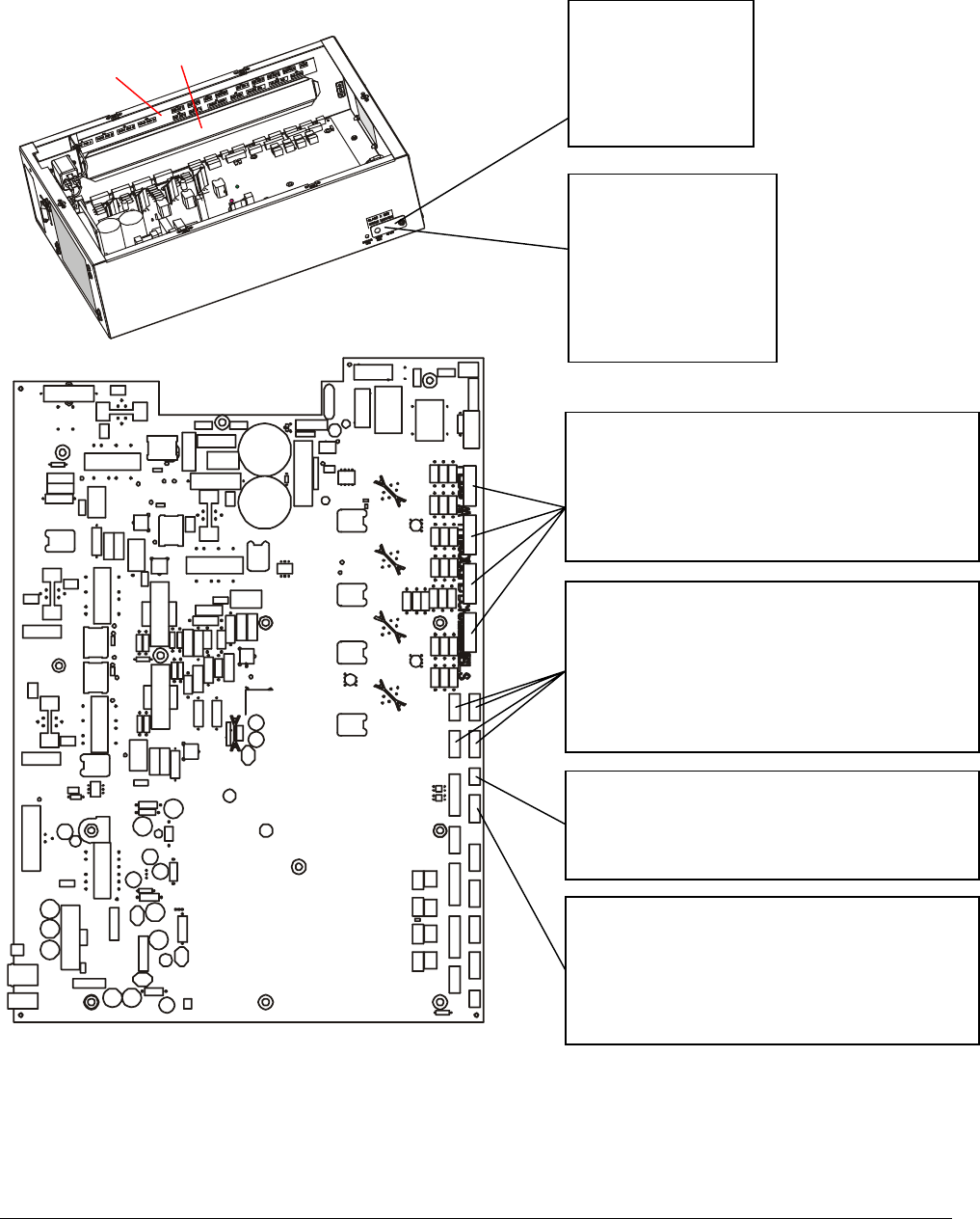
A label inside the controller identifies connectors.
Label
Cables pass into enclosure
through here.
AMS-9040 Circuit Board
AMS-9040 Controller
SERVICE (RS232)
(Behind Cover)
Pin 1 - Rx
Pin 2 - Tx
Pin 3 - Ground
Pin 4 - Ground
SYNC LINK
(Behind Cover)
Pin 1 - Ground
Pin 2 - Sync Link out
Pin 3 - Sync Link in
Pin 4 - Ground
Pin 5 - Ground
Pin 6 - Vbus
Tx/Rx: PED A (P1), B (P24), C (P4), D (P35)
Pin 1 - Black (Bottom coil return)
Pin 2 - Red (Bottom coil)
Pin 3 - Green (Top coil return)
Pin 4 - White (Top coil)
Pin 5 - White with an 'X' (Shield)
GENERAL-PURPOSE AUX. RECEIVE
A
(P27), B (P29), C (P31), D (P33)
Pin 1 - Black (Coil 1)
Pin 2 - Red (Coil 1 return)
Pin 3 - Green (Coil 2 return)
Pin 4 - White (Coil 2)
Pin 5 - White with an 'X' (Shield)
ULTRA LINK ALARM MANAGEMENT (P41)
Pin 1 - Black
Pin 2 - Red
Pin 3 - White with an 'X' (Shield)
Continued, next page
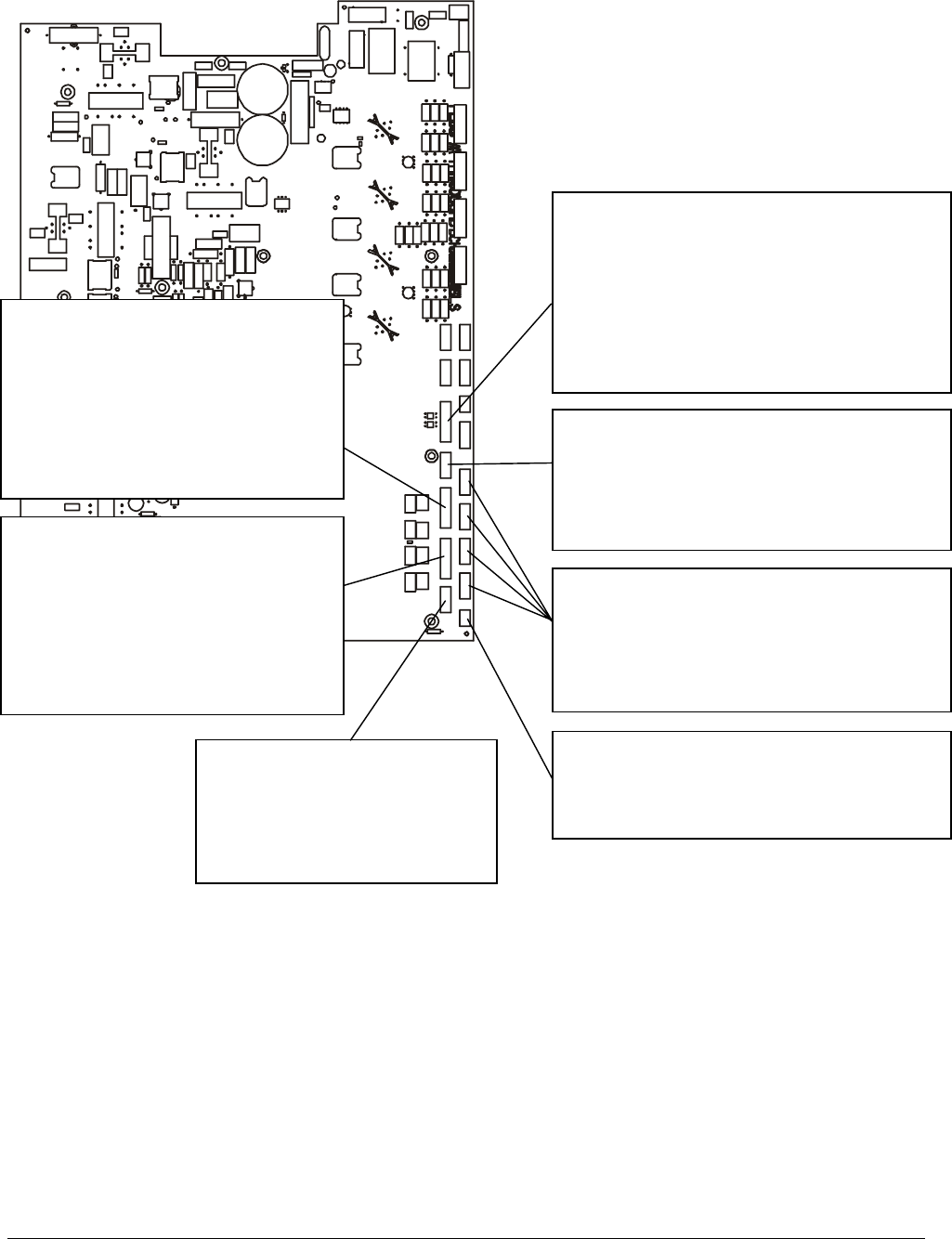
BEACON LAMP (P10)
Pin 1 - Black (Lamp A)
Pin 2 - Red (+12V signal lamp A)
Pin 3 - Black (Lamp B)
Pin 4 - Red (+12V signal lamp B)
Pin 5 - White with an 'X' (Shield lamp A/B)
AMS-9040 CONTROLLER 8200-0367-02, REV. 9
INSTALLATION AND SERVICE GUIDE 4 of 20
Company Confidential
AMS-9040 CONTROLLER 8200-0367-02, REV. 9
Continued from previous page
REMOTE ALARMS (P7)
Pin 1 - 12V return
Pin 2 - 12V alarm
Pin 3 - Alarm 0
Pin 4 - 12V return
Pin 5 - 12V alarm
Pin 6 - Alarm 1
Pin 7 - Shield (Alarm 0/1)
Pin 8 - NC
INSTALLATION AND SERVICE GUIDE 5 of 20
RELAYS C-D (P9)
Pin 1 - C (Relay C)
Pin 2 - NC (Relay C)
Pin 3 - NO (Relay C)
Pin 4 - White with an 'X' (Relay C Shield)
Pin 5 - C (Relay D)
Pin 6 - NC (Relay D)
Pin 7 - NO (Relay D)
Pin 8 - White with an 'X' (Relay D Shield)
WIRED Tx SYNC (P2)
Pin 1 - Black (Tx Burst High)
Pin 2 - Red (Tx Burst Low)
Pin 3 - Green (Arm High)
Pin 4 - White (Arm Low)
Pin 5 - White with an 'X' (Shield)
A
NT COM: PED A (P5), B (P25), C (P6), D (P36)
Pin 1 - Black (12V Return)
Pin 2 - Brown (RS485 Low)
Pin 3 - Red (RS485 High)
Pin 4 - Orange (12V Alarm)
Pin 5 - White with an 'X' (Shield)
RELAYS A-B (P12)
Pin 1 - C (Relay A)
Pin 2 - NC (Relay A)
Pin 3 - NO (Relay A)
Pin 4 - White with an 'X' (Relay A Shield)
Pin 5 - C (Relay B)
Pin 6 - NC (Relay B)
Pin 7 - NO (Relay B)
Pin 8 - White with an 'X' (Relay B Shield)
RS485 (P8)
Pin 1 - Black (RS485 Low)
Pin 2 - Red (RS485 High)
Pin 3 - White with an 'X' (Shield)
PED INHIBIT (P26)
Pin 1 - Black (Ped A)
Pin 2 - Red (Ped B)
Pin 3 - Green (Ped C)
Pin 4 - White (Ped D)
Pin 5 - White with an 'X' (Shield)

Company Confidential
Remote Alarm Connections (P7)
This connector can power and control up to two
remote alarms, such as a ZC30 or ZC35.
Beacon Lamp Connections (P10)
This connector can power and control up to two
beacon lamps, supplying up to 12V at 1A for each
lamp.
Relay Connections (P9, P12)
The controller has four double pole double throw
(DPDT) relays, each programmed independently.
These relays are used to trigger devices such as
externally powered remote alarms and beacon
lamps, time lapse VCRs, and security cameras,
one device per detection zone.
Each relay requires three wires and a shield. Cable
shields share one pin on the connector.
Alarm Management and RS485
Connections (P41, P8)
“Ultra” connector P41 powers a Sensormatic alarm
management device. Connector P8 supports
RS485 communication to the device.
Wired Tx Sync Connection (P2)
This connector is used to wire two AMS-9040
controllers together to synchronize them so they do
not interfere with each other.
Note: The controller also provides for a slower
sequencer level synchronization to allow two
Digital Floor-Max antennas to be placed next to
each other when driven by different controllers.
Wireless AC Sync Connection
(On Controller)
Protected by a cover plate, this connector receives
a cable from a Sync Link device which, when
connected, is automatically used as the timing
reference for system functions. See “Automatic AC
Line Synchronization” on page 7. Also, see
Appendix A.
RS232 Service Connection
(On Controller)
Protected by a cover plate, this RJ22 connector
receives the cable from a modem or laptop
computer used to communicate with the controller.
Ped (Tx) Inhibit Connection (P26)
This connector has a maximum of four Tx Inhibit
pins, each configurable using the service
configurator. Each pin, when grounded, turns off a
specified transmitter.
AMS-9040 CONTROLLER 8200-0367-02, REV. 8
INSTALLATION AND SERVICE GUIDE 6 of 20
Company Confidential
Installation Features
Installation features are as follows:
- Automatic detect and setup functions
- Controller-assisted antenna tuning
- Transmitter current control
- Wall mounted controller. Requires mounting
bracket with extension.
Automatic Detect and Setup Functions
Device Detect. The controller automatically
detects digital AM antennas, when they are
connected to the controller and the controller is
powered on. Once these antennas are auto-
detected, the controller sets them up as
transceivers and sets their sequence of operation
to “simultaneous-alternating” as shown below.
ANTENNA SEQUENCE
Digital Pro*Max Simultaneous–Alternating
Digital Door*Max Simultaneous–Alternating
Digital Euro Pro*Max Simultaneous–Alternating
Digital Floor*Max Alternating maximum
repetition rate is 45Hz.
Unknown Alternating maximum
repetition rate is 45Hz
(60Hz), or 37.5Hz (50Hz).*
* When an antenna without device identification, such
as an Ultra*Post secondary antenna, is detected,
the repetition rate does not exceed this value due to
de-rating of capacitors on the capacitor tuning circuit
board.
The controller also detects a SyncLink device,
when connected. See page 6.
Automatic ac line synchronization. Upon power
up or system reset, the controller automatically
adjusts its operation to the ac input’s frequency
and voltage.
Also, to avoid interference from nearby EAS
detectors, upon power up or system reset, the
controller automatically adjusts the ac-derived
timing of its transmit and receive functions to that
of nearby EAS transmitters, if detected. Auto sync
status is displayed on the service configurator.
Note: If a Sync Link device is connected to the
controller, the controller automatically uses its
signal as the timing reference instead. The service
configurator indicates that Sync Link is active.
Controller-Assisted Antenna Tuning
A series of LEDs on the tuning circuit board of a
digital AM antenna indicate to field personnel when
and where tuning jumpers are to be placed for
optimum antenna performance. For specific
information, see the installation guide supplied with
the antenna.
Note: Proper AC line delay must be selected
before performing controller-assisted tuning.
Transmitter Current Control
The controller allows transmit current to be
adjusted to the maximum allowed for the region of
use.
- The controller checks current in each transmitter
and the antenna coil configuration: aiding or
figure-8.
- If current reaches a pre-determined level, a
signal is sent to software that indicates current
is excessive and which antenna is affected. The
controller also shuts down the transmitter for
one second before operation resumes.
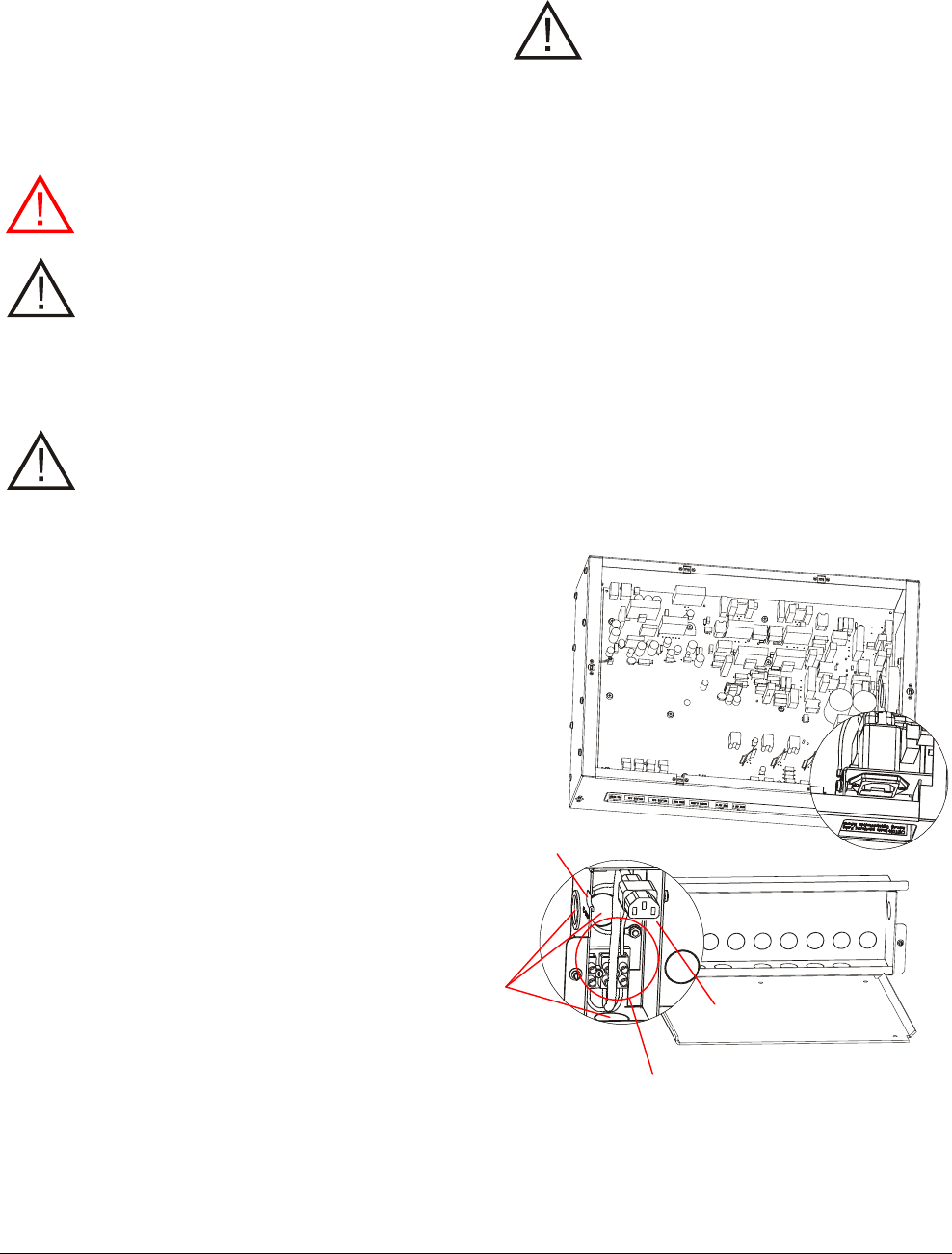
Mounting the Controller
DO NOT mount the controller with its fan
facing up!
Using the mounting bracket supplied, the controller
can be mounted as follows:
- On a shelf.
- On a wall. If required, use the extension bracket
provided to enable mounting screws to thread
into wall studs. DO NOT mount the controller
with its fan facing up!
- To a ceiling. Secure a piece of plywood larger
than the mounting bracket to the ceiling
structure that holds the drywall. Then attach the
bracket to the plywood.
!
AMS-9040 CONTROLLER 8200-0367-02, REV. 8
INSTALLATION AND SERVICE GUIDE 7 of 20

Company Confidential
Service Features
Service features are as follows:
- Laptop computer service configurator
- Internal diagnostics
- LED status indicator
- Remote diagnostics via modem, Ethernet, or
RS485 network. Must have external converter
to support Ethernet.
Service Configurator
A service configurator downloaded to a laptop
computer is required to setup and troubleshoot the
controller. The service configurator allows you to:
- Set antenna coil configuration as aiding or
figure-8
- Customize detection for each antenna
- Monitor transmit and noise levels from each
antenna
- Monitor transmit current from each antenna
- Customize alarm setup
- Turn off transmitters (via pedestal inhibit port)
- Monitor temperature inside the controller
- Download new software features/updates to
flash memory
- Provide a system error report
- Separate a problem into one of three
categories: controller, environment, or the
device connected to the controller, such as
antennas or remote alarms.
Note: Special tools are not required when installing
the controller as long as antennas are installed in a
reasonable noise environment and local
transmitters are properly adjusted.
Note: If default settings are changed, you do not
need to turn the controller off and on to store them.
Operating software required: Windows® 95, 98,
2000, or XP.
Internal Diagnostics
The controller provides the following internal
diagnostics:
- The service configurator displays operating
current for each antenna.
- The service configurator displays ambient
temperature within the controller.
- The service configurator enables the controller
to be reset remotely after a software download.
- The controller has runaway software protection.
- Board diagnostics.
LED System Status Indicator
An LED system status indicator on the controller
indicates the following:
- Green flashing (system on and okay)
- Yellow flashing (performance downgraded;
service recommended)
- Red flashing in a particular sequence (fault
detected, call for service).
The number of red flashes identifies a digit in a
two-digit alert code (for example, four flashes is
the number four). The start of an alert code is
indicated by a long LED interval. Then the first
digit of the code occurs, followed by a short
delay, followed by the second digit.
Alert codes are listed on page 15.
Remote Diagnostics
Remote diagnostics enables the use of a computer
at another location to troubleshoot problems and
change controller parameters.
- The controller must be connected to a properly
programmed modem and telephone line, or to
an Ethernet or RS485 network.
- An external adapter is required.
AMS-9040 CONTROLLER 8200-0367-02, REV. 8
INSTALLATION AND SERVICE GUIDE 8 of 20
Company Confidential
Installation
Installation Requirements
Verifying Equipment and Unpacking
- Verify that all equipment has arrived. Ensure the
system configuration is the right one for the
installation site.
- Unpack major components in a back room. At
the install site, lay out parts in the order you will
need them. Do not clutter the aisle or cause a
trip hazard.
Installer/Contractor
- Have electrical work comply with the latest
national electrical code, national fire code, and
all applicable local codes and ordinances.
- Coordinate work with other trades to avoid
interference.
- Verify existing site conditions and coordinate
with the owner’s representative and appropriate
utilities as required.
- Obtain copies of all related plans, specifications,
shop drawings and addenda to schedule and
coordinate related work.
- Thoroughly review the project to ensure that all
work meets or exceeds the above requirements.
Bring alleged discrepancies to the attention of
Sensormatic Electronics.
Controller Requirements
If using conduit:
- In the cable tray part of the cable tray/mounting
bracket assembly, there are three ½” or ¾”
knockouts for hardwired ac power and nineteen
½" or ¾" knockouts for antenna and other
cables.
- Select knockouts closest to cable connectors.
- DO NOT route more cables through conduit
than regulation allows.
Mounting limitations are as follows:
- The wall must support 29.2kg (64.6 lbs) or four
times the weight of the controller assembly.
- Mounting options are mounting directly to two
metal or wood wall studs, mounting indirectly to
a wood board attached to two metal or wood
studs, mounting to drywall using suitable
hardware that can support the weight, or placing
the controller on a shelf.
- When mounting to wall studs, if holes in the
controller’s integral cable tray/mounting bracket
assembly do not align with the two wall studs,
use the extension bracket supplied to achieve
alignment.
- Do not mount controller with its fan facing up.
WARNING! Do not install this product
where highly combustible or explosive
products are stored or used.
WARNING—RISK OF ELECTRIC
SHOCK! During installation, if the
antenna must be left unattended, turn off
the power or cover high voltage
components to prevent unauthorized
access to hazardous voltages.
Antenna Requirements
See antenna installation guide for antenna
installation requirements.
Equipment Required
Basic setup requires the following equipment:
• Antenna controller
• Digital AM antennas (installation instructions are
supplied with the antenna)
• Hard tag (non-deactivateable Ultra•Max tag)
• Ultra•Max low energy labels.
Advanced setup requires the following additional
equipment:
• Laptop with Windows® 95, 98, 2000, or XP
operating software
• RS232 Ultra•Max programming cable
• Service configurator.
Parts Required
Bracket, extension 1 0500-9792-01
Tray, cable 1 0404-0175-01
!
AMS-9040 CONTROLLER 8200-0367-02, REV. 8
INSTALLATION AND SERVICE GUIDE 9 of 20
Company Confidential
Installation Procedure
This section describes installation procedures for
when the controller is to rest on a shelf, or be
attached to a wall or ceiling.
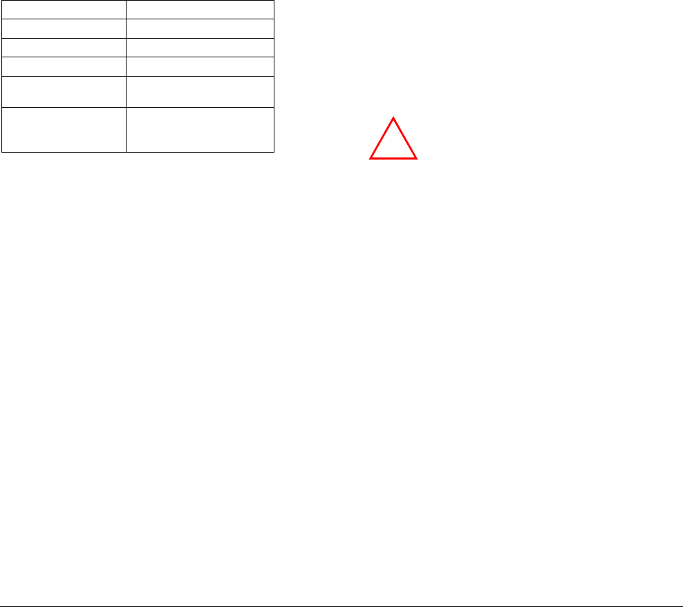
When Controller Rests on a Shelf
1. Remove the cover from the top of the controller,
then detach the integral cable tray/mounting
bracket assembly from the controller. Two
captive ¼-turn fasteners secure the assembly.
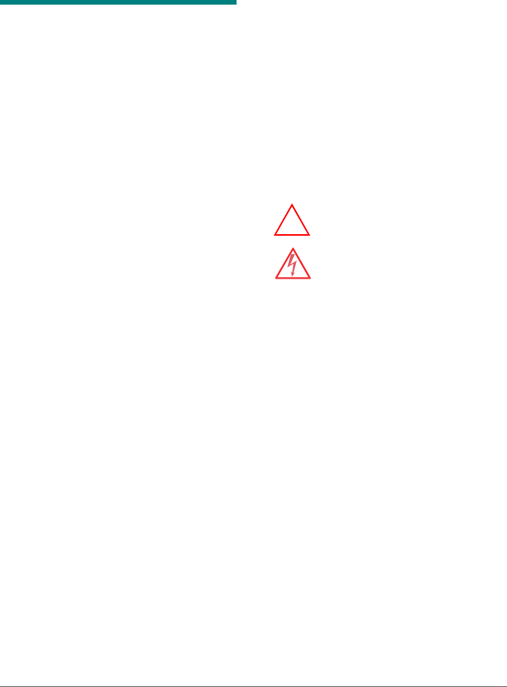
2. Of the 19 knockouts in the cable tray dedicated
to cables, remove the ones closest to the
connectors they are associated with. DO NOT
remove the three knockouts used to access the
ac connection area. Observe Class 2, Class 2
“wet”, and Class 3 requirements silkscreened
on the cable tray.
3. Thread cable clamps into the holes. Run cables
(except power) through the cable clamps
leaving about 30cm (12in) of excess on the
other side. Tighten the clamps.
4. Attach connectors supplied to the cables, route
cables through the rectangular opening in the
controller housing, and referring to the diagrams
on pages 4 and 5, plug them into the
appropriate circuit board connectors:
a. Transceiver antenna(s)
b. Antenna communication line(s)
c. Auxiliary receive antenna(s), if required
Controller
d. Remote alarm(s), if required
e. Beacon lamp(s), if required
f. External alarm(s) or other triggered device, if
required
g. Wired Sync, if required
h. Sync Link, if required
i. RS485 network, if required
j. Alarm management device, if required.
5. Connect ac power (see page 13).
6. Attach the controller to the cable tray/mounting
bracket assembly using the two ¼-turn
fasteners.
3 knockouts for hardwired AC
(1 on underside)
19 knockouts for cables
(1 on side, 8 on underside)
Bracket
A
ssembly
¼-turn fasteners (2)
AMS-9040 CONTROLLER 8200-0367-02, REV. 8
INSTALLATION AND SERVICE GUIDE 10 of 20
Company Confidential
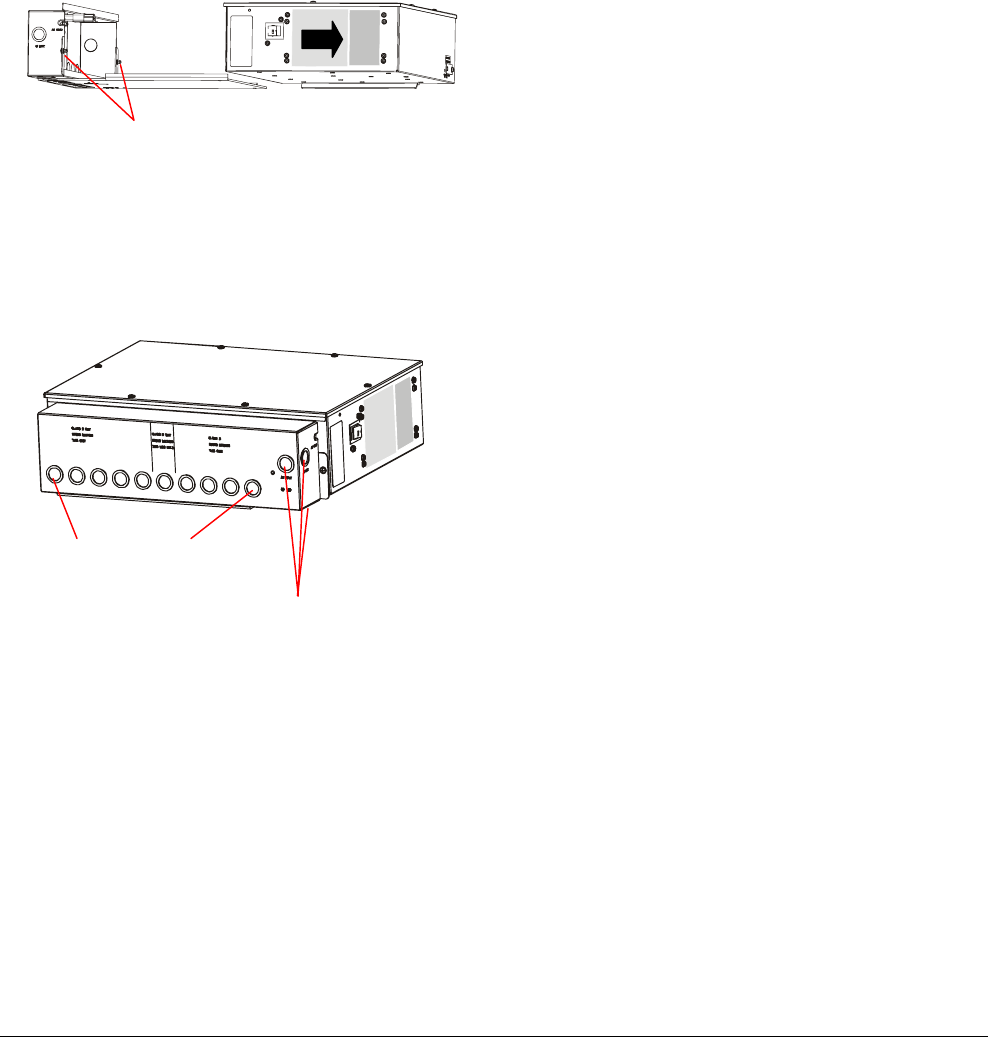
Wall Mounting
WARNING! The wall must be able to
support 29.2kg (64.6 lbs).
1. Remove the cover from the top of the controller,
then detach the integral cable tray/mounting
bracket assembly from the controller. Two
captive ¼-turn fasteners secure the assembly.
2. Place the bracket part of the assembly on the
wall, level it, and mark mounting hole locations.
WARNING! Mounting hole locations
must align with two wall studs. If not,
use the extension bracket supplied.
3. Secure the cable tray/mounting bracket
assembly to each of two wall studs.
4. Of the 19 knockouts in the cable tray dedicated
to cables, remove the ones closest to the
connectors they are associated with. DO NOT
remove the three knockouts used to access the
ac connection area. Observe Class 2, Class 2
“wet”, and Class 3 requirements.
5. If using cable clamps: Thread cable clamps
into the holes. Run cables (except power)
through the cable clamps leaving about 30cm
(12in) of excess on the other side. Tighten the
clamps.
If using conduit: Attach conduit to the cable
tray and run cables to the controller.
6. Attach connectors supplied to the cables, route
cables through the rectangular opening in the
controller housing, and referring to the diagrams
on pages 4 and 5, plug them into the
appropriate circuit board connectors:
Controller
Bracket
A
ssembly a. Transceiver antenna(s)
b. Antenna communication line(s)
¼-turn fasteners (2) c. Auxiliary receive antenna(s), if required
d. Remote alarm(s), if required
e. Beacon lamp(s), if required
f. External alarm(s) or other triggered device, if
required
g. Wired Sync, if required
h. Sync Link, if required
i. RS485 network, if required
j. Alarm management device, if required.
7. Connect ac power (see page 13).
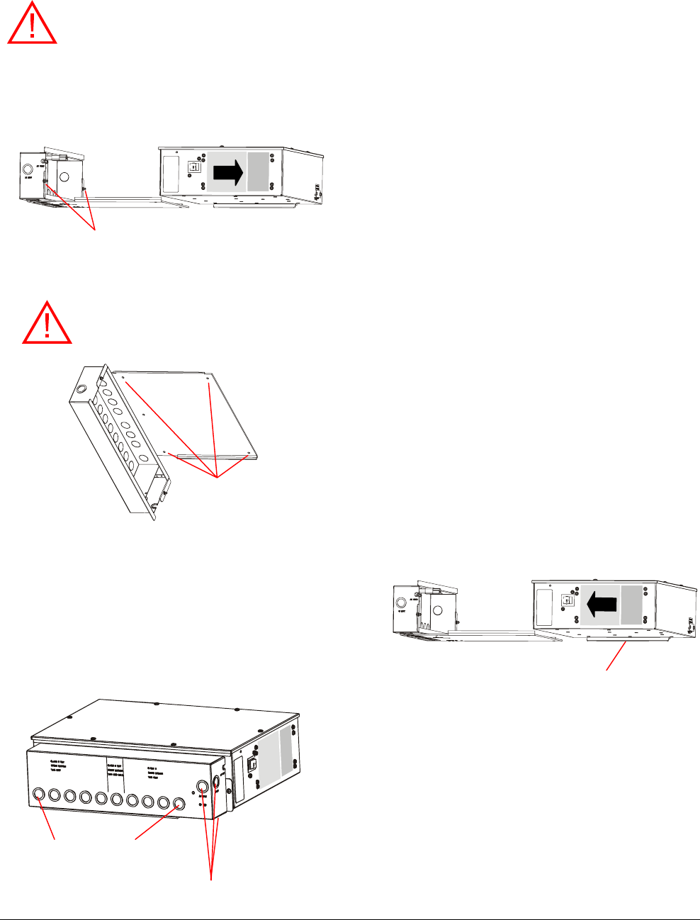
8. Attach the controller to the cable tray/mounting
bracket assembly using the two ¼-turn
fasteners.
Note: If mounting with the cable tray vertical,
hook the metal flange attached to the bottom of
the controller onto the mounting bracket to hold
the controller in place while you slide it into
position.
Ensure mounting
holes align with
wall studs.
3 knockouts for hardwired AC
(1 on underside)
19 knockouts for cables
(1 on side, 8 on underside)
Flange
AMS-9040 CONTROLLER 8200-0367-02, REV. 8
INSTALLATION AND SERVICE GUIDE 11 of 20
Company Confidential
Ceiling Mounting
MS-9040 CONTROLLER 8200-0367-02, REV. 8
INSTALLATION AND SERVICE GUIDE 12 of 20
WARNING! The ceiling must be able to
support 29.2kg (64.6 lbs).
1. Remove the cover from the top of the controller,
then detach the integral cable tray/mounting
bracket assembly from the controller. Two
captive ¼-turn fasteners secure the assembly.
2. Cut a piece of plywood larger than the mounting
bracket and large enough to attach two ceiling
beams that support the drywall or hard ceiling.
Secure the plywood to the beams using suitable
hardware.
3. Place the bracket part of the assembly on the
plywood and mark mounting hole locations.
Then secure the cable bracket to the plywood.
4. Of the 19 knockouts in the cable tray dedicated
to cables, remove the ones closest to the
connectors they are associated with. DO NOT
remove the three knockouts used to access the
ac connection area. Observe Class 2, Class 2
“wet”, and Class 3 requirements.
Controller
5. If using cable clamps: Thread cable clamps
into the holes. Run cables (except power)
through the cable clamps leaving about 30cm
(12in) of excess on the other side. Tighten the
clamps.
If using conduit: Attach conduit to the cable
tray and run cables to the controller.
7. Attach connectors supplied to the cables, route
cables through the rectangular opening in the
controller housing, and referring to the diagrams
on pages 4 and 5, plug them into the
appropriate circuit board connectors:
a. Transceiver antenna(s)
b. Antenna communication line(s)
c. Auxiliary receive antenna(s), if required
d. Remote alarm(s), if required
e. Beacon lamp(s), if required
f. External alarm(s) or other triggered device, if
required
g. Wired Sync, if required
h. Sync Link, if required
i. RS485 network, if required
j. Alarm management device, if required.
8. Connect ac power (see page 13).
9. Attach the controller to the cable tray/mounting
bracket assembly using the two ¼-turn
fasteners.
Ensure mounting
holes align with
wall studs.
3 knockouts for hardwired AC
(1 on underside)
19 knockouts for cables
(1 on side, 8 on underside)
Bracket
A
ssembly
¼-turn fasteners (2)
A
Company Confidential
Power Connections
Ac power connects to the controller using a power
cord or hardwired cable.
- The power source can be 100-120Vac
or 220-240Vac.
- The controller automatically senses the voltage
so no jumper settings are required.
WARNING—RISK OF ELECTRIC
SHOCK! The ac power cord could be
carrying 120Vac or 240Vac.
CAUTION: When using a power cord, a
socket-outlet must be installed near the
controller and in an easily accessible
location.
Für Installationen mit einem Stromkabel muß
die Steckdose an einem Standort installiert
werden, welcher einfachen Zugang erlaubt.
CAUTION: A 6A, 2 pole, ganged
disconnect device, which also provides
short circuit and overload protection, and
has a minimum 3mm open circuit
clearance, in accordance with the
National Electric Code and applicable
local codes must be installed by a
licensed electrician at a location readily
accessible to the equipment.
Ein 6A, 2-poliges, gekoppeltes
Ausschaltgerät, welches auch über einen
Kurzschluß- sowie Überbelastungsschutz
verfügt, und einen minimum 3mm offenen
Schaltabstand aufweist, nach
Übereinstimmung mit den Nationalen
Elektrischen Regelungen sowie lokalen
Regeln, muß an einem Standort installiert
werden, welcher einfachen Zugang zum
Gerät erlaubt.
Power Cord
Referring to the figure opposite:
1. Route the power cord through the U-shaped
opening accessing the ac connection area in
the cable tray. DO NOT remove the three
knockouts used to access the ac connection
area.
2. Plug the cord into the IEC320 receptacle in the
controller housing.
3. Return to the installation procedure beginning
on page 10.
Hardwired Cable
CAUTION: Use only copper wire.
Referring to the figure below:
1. Remove one of the three knockouts accessing
the ac connection area in the cable tray. Thread
a cable clamp into the hole.
2. Route the ac cable through a cable clamp,
leaving about 15.2cm (6in) out the other side.
Tighten the clamp around the cable.
3. Expose about 5cm (2in) of insulated wires: hot,
common, and ground.
4. Using a small screwdriver, connect ac wires to
the two-pin connector: white wire to N (neutral);
black wire to L (line). Connect the green wire to
ground on the controller chassis.
5. Plug the short power cord into the IEC320
receptacle in the controller housing.
6. Return to the installation procedures beginning
on page 10.
U-Shaped Opening IEC320
Receptacle
Cable Plug
A
C
Knockouts
(3)
A
C Connections
AMS-9040 CONTROLLER 8200-0367-02, REV. 8
INSTALLATION AND SERVICE GUIDE 13 of 20

Company Confidential
Sample Hookups
Because antennas and equipment can be
connected to the controller in various ways based
on the number of store exits involved, security
zones required, coverage desired, and customer
preferences, system configurations are too
numerous to describe in this document. Instead,
study the sample systems shown in this section to
provide a feel for how to connect these devices.
(TBD)
AMS-9040 CONTROLLER 8200-0367-02, REV. 8
INSTALLATION AND SERVICE GUIDE 14 of 20

Company Confidential
Troubleshooting
System Status Alert Codes
Fault Condition Monitoring
The controller generates alert codes. Software
reads the codes, reports them, and takes
corrective action if possible depending on the code
received. The following critical faults are backed up
with hardware support and provide the necessary
action when encountered.
- Current fault 1 per channel
- Fan fault
- Ambient temperature fault.
- Primary current fault
- Secondary current fault
- Last resort current fault to maintain Class 2
wiring requirements.
Alert codes require different actions: critical,
severe, hardware, and warning. These codes
repeat until the condition is resolved.
1. Critical. Critical and Fatal System Alerts are
displayed on the System Alert LED until a timer
resets the system. If the timer is not enabled, a
unique LED sequence indicates that this
condition has occurred and repeats
continuously.
2. Severe. Severe System Alert codes are
displayed by the System Alert LED and result
in the software recovering from the error in a
deterministic and reliable method.
3. Hardware. Hardware System Alert codes are
displayed by the System Alert LED and result
in the software and hardware working together
to recover from the error in a deterministic and
reliable method when the Alert is resolved.
4. Warning. Warning System Alert codes are
displayed by the System Alert LED and result
in the software recovering from the error in a
deterministic and reliable method.
When a status alert occurs, the LED indicator
changes color and pattern. Red is used for serious
or critical system alerts while yellow is for less
serious alerts and warnings.
- The number of red flashes identifies a digit in a
two-digit error code (for example, four flashes is
the number four). The start of an error code is
indicated by a long LED interval. Then the first
digit of a two-digit error code occurs, followed by
a short delay, followed by the second digit.
- An alert code does not necessarily mean action
is taken; it simply is a notification that the
system is performing some operation. Most alert
conditions are automatically resolved.
- Up to 80 alert codes are displayed by the Status
LED, except codes that begin or end with a zero
such as 0-9 and 10, 20, 30, 40, 50, 60, 70, 80
and 90. Codes not displayed on the LED may
be accessed only via the service configurator.
- Alert codes are stored in RAM and lost when
the controller is reset. Code storage has a time
stamp in days, hours, minutes, seconds,
milliseconds/ ticks of when the system alert
occurred.
Alert Codes
Alert codes are as follows:
11 Illegal Instruction
12 Unimplemented Interrupt
13 NVM Write Failed
14 Invalid Device
15 Sequence Table Error
16 Out of Memory
17 Undecided: No Split
18 Watchdog: Task Reset
21 AntA S/W Current Fault
22 AntB S/W Current Fault
23 AntC S/W Current Fault
24 AntD S/W Current Fault
25 H/W Current Fault
26 AntA Current Sense Fault
27 AntB Current Sense Fault
28 AntC Current Sense Fault
29 AntD Current Sense Fault
31 Ped A Not Tuned
32 Ped B Not Tuned
33 Ped C Not Tuned
34 Ped D Not Tuned
35 Ped A Tuning TX Off
36 Ped B Tuning TX Off
AMS-9040 CONTROLLER 8200-0367-02, REV. 8
INSTALLATION AND SERVICE GUIDE 15 of 20
Company Confidential
37 Ped C Tuning TX Off
38 Ped D Tuning TX Off
39 Sequence Table Mismatch
41 Missing Zero Crossing
42 Wired Sync: Missing Signal
43 Temperature Fault
44 S/W Temperature Fault
45 PWM Fault
46 Fan Fault
49 Realtime Error
51 Autosetup Owner Timeout
52 Autosetup Release W/O Lock
53 Autosetup Buffer Overrun
54 Autosetup Mailbox Full
55
56 Notch Select Timeout
57 Window Select Timeout
58 Autosetup Illegal Owner
61 Detector Overrun
62 Alarm Mailbox Full
63 Host Comm Mailbox Full
64 Host Comm Mailbox Full
71 Host Comm Mailbox Full
S-9040 CONTROLLER 8200-0367-02, REV. 8
INSTALLATION AND SERVICE GUIDE 16 of 20
Controller-Assisted Tuning Disabled
If configurator-assisted tuning cannot be
performed, a message indicating the cause will be
posted on the service configurator. Causes the
software recognizes are:
- Tx set to off in the service configurator.
- Tx inhibit active.
- Auto line delay not ready.
- Key switch turned to off (locked).
Once the CE has turned the transmitter on,
controller-assisted tuning can be performed.
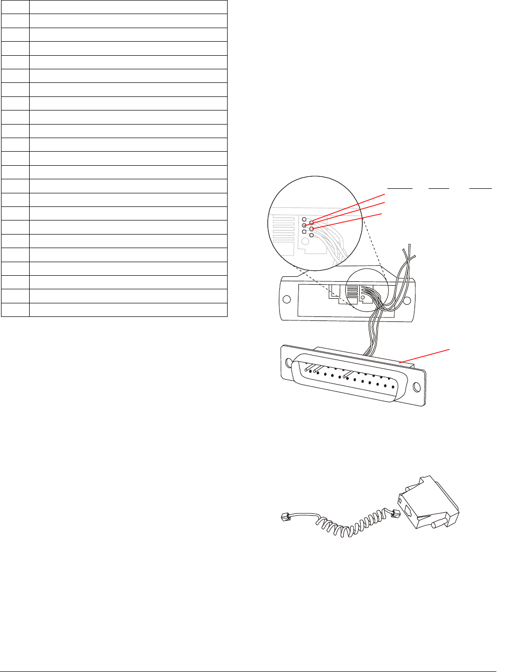
Laptop/Modem Connections
A modem enables you to use your computer to
dial-up the controller for remote service.
Hardware required is as follows:
• External modem
• DB25 male to RJ12/RJ11 female connector
• RJ11 male to RJ10 male cable
Procedure
1. Prepare the DB25 to RJ12/RJ11 null modem
connector.
1
2
2
34
56
37
Signal RJ12 DB25
Rx Pin 2 Pin 3
Tx Pin 3 Pin 2
Gnd Pin 4 Pin 7
RJ12/RJ11
Inside View
DB25
2. Connect the DB25 connector to the modem.
3. Connect the RJ11 connector to the DB25 to
RJ12/RJ11 connector.
AM
Company Confidential
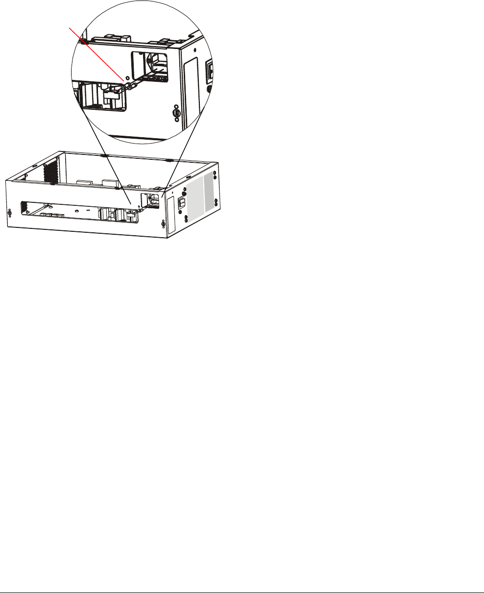
Fuse Replacement
The controller contains two 5A, 250V, slow-blow
fuses. To replace the fuse(s) in the controller, do
the following:
Fuses (2)
1. Detach the controller from the cable tray. Two
screws secure the tray, one on each side.
2. On the controller, pry the rectangular cover
plate from the IEC320 receptacle using a small
slotted screwdriver. Two spring-loaded fuses
should pop out.
3. Replace the blown fuse (or fuses) with 5A,
250V slow-blow fuses (P/N 5111-0028-11).
4. Reattach the cover plate to the receptacle.
5. Attach the controller to the cable tray using two
screws previously removed.
AMS-9040 CONTROLLER 8200-0367-02, REV. 8
INSTALLATION AND SERVICE GUIDE 17 of 20

Company Confidential
Specifications
Electrical
Power Supply
Primary input ............................100-120Vac or
220-240Vac @ 50–60Hz
Primary power fuse...................5A, 250V, slo-blow,
hi-breaking
Current draw.............................4.0Arms @ 120Vac
Input power...............................<400W
Transmitter
Operating frequency .................58 kHz (±200Hz)
Transmit burst duration.............1.6ms
Transmit current maximum.......16A peak
Burst Repetition Rate:
Based on 50Hz ac ....................75Hz or 37.5Hz
Based on 60Hz ac ....................90Hz or 45Hz
Receiver
Center frequency ......................58 kHz
Receive coil resistance.............1.6 ohms (±5%)
Alarm
Alarm relay output.....................DPDT contacts
Contact switching current .........1.0A max.
Contact switching voltage.........28V max.
Lamp/Audio duration.................1–30 sec.
(1 sec. increments)
Environmental
Ambient temperature ................0°C to 50°C
(32°F to 122°F)
Relative humidity ......................0 to 90%
non-condensing
Mechanical
Length.......................................50.8cm (20in)
Width with bracket ....................43.4cm (17.1in)
Width without bracket ...............32.2cm (14.3in)
Height .......................................15cm (5.9in)
Weight ......................................7.3kg (16.1lbs.)
Declarations
Regulatory Compliance
EMC.............................. 47 CFR, Part 15
EN 300330-1 U1.3.2 (2002)
ETSI EN 300330-2 V1.1.1
(2001-06)
ETSI EN 301489-3 V 1.2.1
(2000-08)
ETSI EN 301489-1 V 1.2.1
(2000-08)
RSS210
Safety............................ UL 60950
CSA C22.2 No 60950
EN 60950
FCC COMPLIANCE: This equipment complies with Part 15
of the FCC rules for intentional radiators and Class A digital
devices when installed and used in accordance with the
instruction manual. Following these rules provides reasonable
protection against harmful interference from equipment
operated in a commercial area. This equipment should not be
installed in a residential area as it can radiate radio frequency
energy that could interfere with radio communications, a
situation the user would have to fix at their own expense.
EQUIPMENT MODIFICATION CAUTION: Equipment
changes or modifications not expressly approved by
Sensormatic Electronics Corporation, the party responsible for
FCC compliance, could void the user's authority to operate the
equipment and could create a hazardous condition.
Other Declarations
WARRANTY DISCLAIMER: Sensormatic Electronics
Corporation makes no representation or warranty with respect
to the contents hereof and specifically disclaims any implied
warranties of merchantability or fitness for any particular
purpose. Further, Sensormatic Electronics Corporation
reserves the right to revise this publication and make changes
from time to time in the content hereof without obligation of
Sensormatic Electronics Corporation to notify any person of
such revision or changes.
LIMITED RIGHTS NOTICE: For units of the Department
of Defense, all documentation and manuals were developed at
private expense and no part of it was developed using
Government Funds. The restrictions governing the use and
disclosure of technical data marked with this legend are set
forth in the definition of “limited rights” in paragraph (a) (15)
of the clause of DFARS 252.227.7013. Unpublished - rights
reserved under the Copyright Laws of the United States.
TRADEMARK NOTICE: Sensormatic is a registered
trademark of Sensormatic Electronics Corporation. Other
product names mentioned herein may be trademarks or
registered trademarks of Sensormatic or other companies.
No part of this guide may be reproduced in any form without
written permission from Sensormatic Electronics Corporation.
MDR 04/04
AMS-9040 CONTROLLER 8200-0367-02, REV. 8
INSTALLATION AND SERVICE GUIDE 18 of 20

Company Confidential
Appendix A:
About Auto Sync
Note: Auto Sync is expected to be only about 80%
reliable due to external environmental issues.
Initialization Phase
Auto sync initialization occurs during power up or
system reset. During initialization, auto sync can
have four different outcomes depending on
whether or not nearby EAS transmitters are
detected, whether they are properly aligned with
the ac-derived functions of the controller, and
whether too much ambient noise exists
No transmitters detected. During initialization, the
controller determines if EAS transmitters are
nearby. If none are found, transmitter delay is set
to zero if this is the initial power on, or set to the
value stored in NVM if this is not the initial power
on. The service configurator displays "No Signal”
and normal operation proceeds.
Transmitters detected and aligned. During
initialization, the controller determines if EAS
transmitters are nearby. If transmitters are found,
and are correctly aligned, transmitter delay is
calculated and set to that value, and the value is
stored in the controller for reference. The service
configurator displays “Locked” and normal
operation proceeds.
Transmitters detected and unaligned. During
initialization, the controller determines if EAS
transmitters are nearby. If transmitters are found,
and are not correctly aligned, transmitter delay is
set to zero if this is the first power on of the
controller, or if not, the delay value is set according
to the value retrieved from the controller and the
service configurator displays “Too Many Signals”.
Operation continues as normal. The user is
advised that system performance might be
compromised. The yellow LED flashes to indicate
system performance is downgraded.
Too much ambient noise. During initialization, the
controller determines if EAS transmitters are
nearby. If noise in the environment prevents the
location other transmitters and if this is the first
power on of the controller, the delay is set to zero.
If this is not the first power on of the controller, the
zero crossing delay is retrieved from storage within
the controller and the service configurator displays
“Too Much Noise”. Operation continues as normal.
The user is advised that the system performance
might be compromised. The status LED flashes
yellow to indicate system performance is
downgraded.
Note: The controller stores the zero crossing delay
for the instance when, during subsequent power
cycles, the controller could not determine a reliable
lock. Instead of using zero for the delay, the
controller uses the zero crossing delay stored.
Sync Link Detection
The Sync Link port is scanned for activity. If activity
is found, the controller automatically switches over
to using the Sync Link signal as the timing
reference. The service configurator indicates that
the Sync Link is active.
Note: If the Sync Link device does not receive the
timing reference signal, it will add up to 60
additional pulses (±100µs). If the controller stops
receiving the required pulse signals, it will measure
the delay from the zero crossing to the SYNCB
signal and start transmitting at that delay until it
reacquires the Sync Link pulse.
AMS-9040 CONTROLLER 8200-0367-02, REV. 8
INSTALLATION AND SERVICE GUIDE 19 of 20

Company Confidential
AMS-9040 CONTROLLER 8200-0367-02, REV. 8
INSTALLATION AND SERVICE GUIDE 20 of 20