Tyco Safety Sensormatic BIC4170 Indoor Ceiling Mount Surveillance Transceiver User Manual
Tyco Safety Products/Sensormatic Indoor Ceiling Mount Surveillance Transceiver Users Manual
UserManual.wiki
>
Tyco Safety Sensormatic
>
BIC4170 User Manual
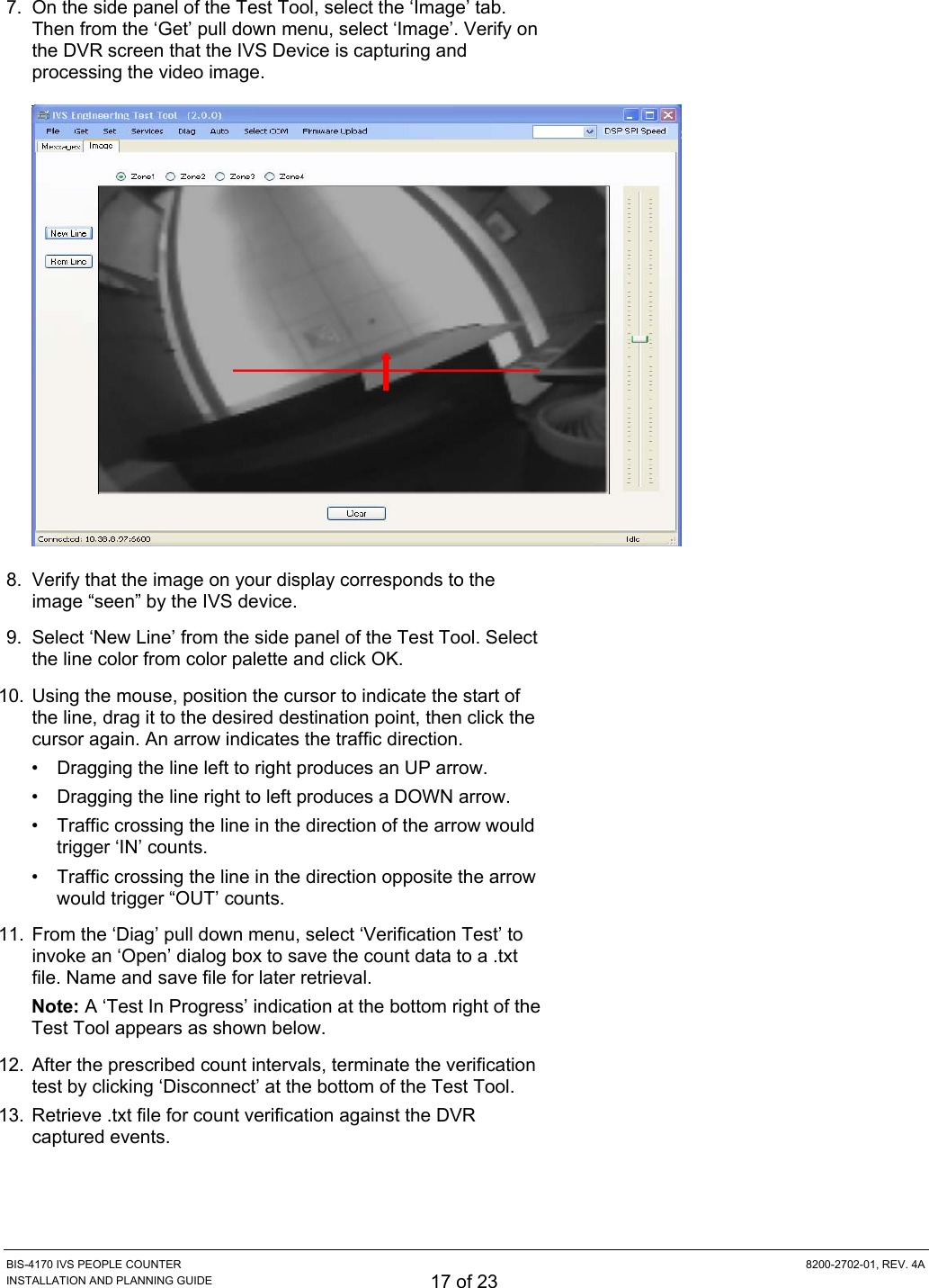
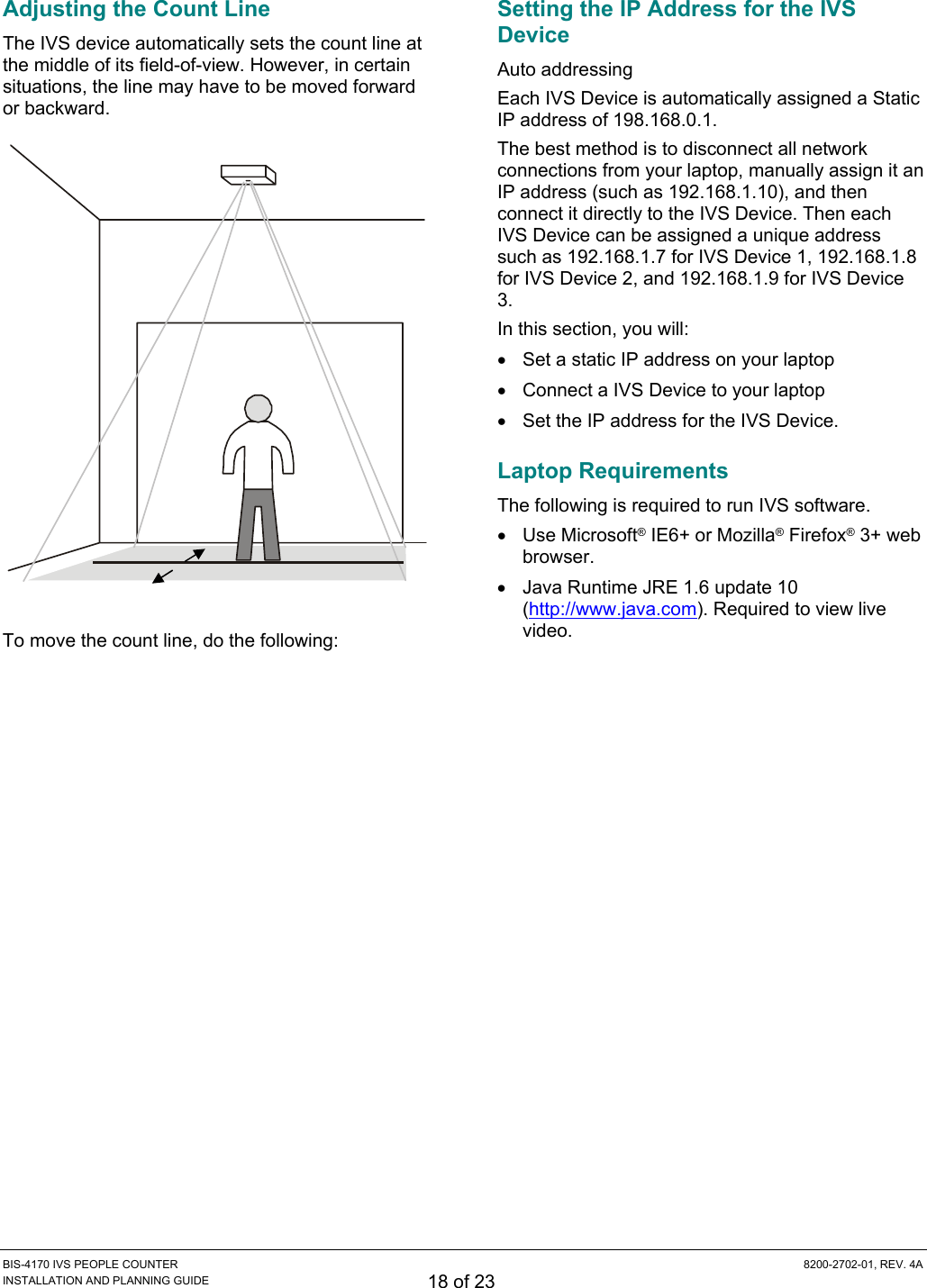
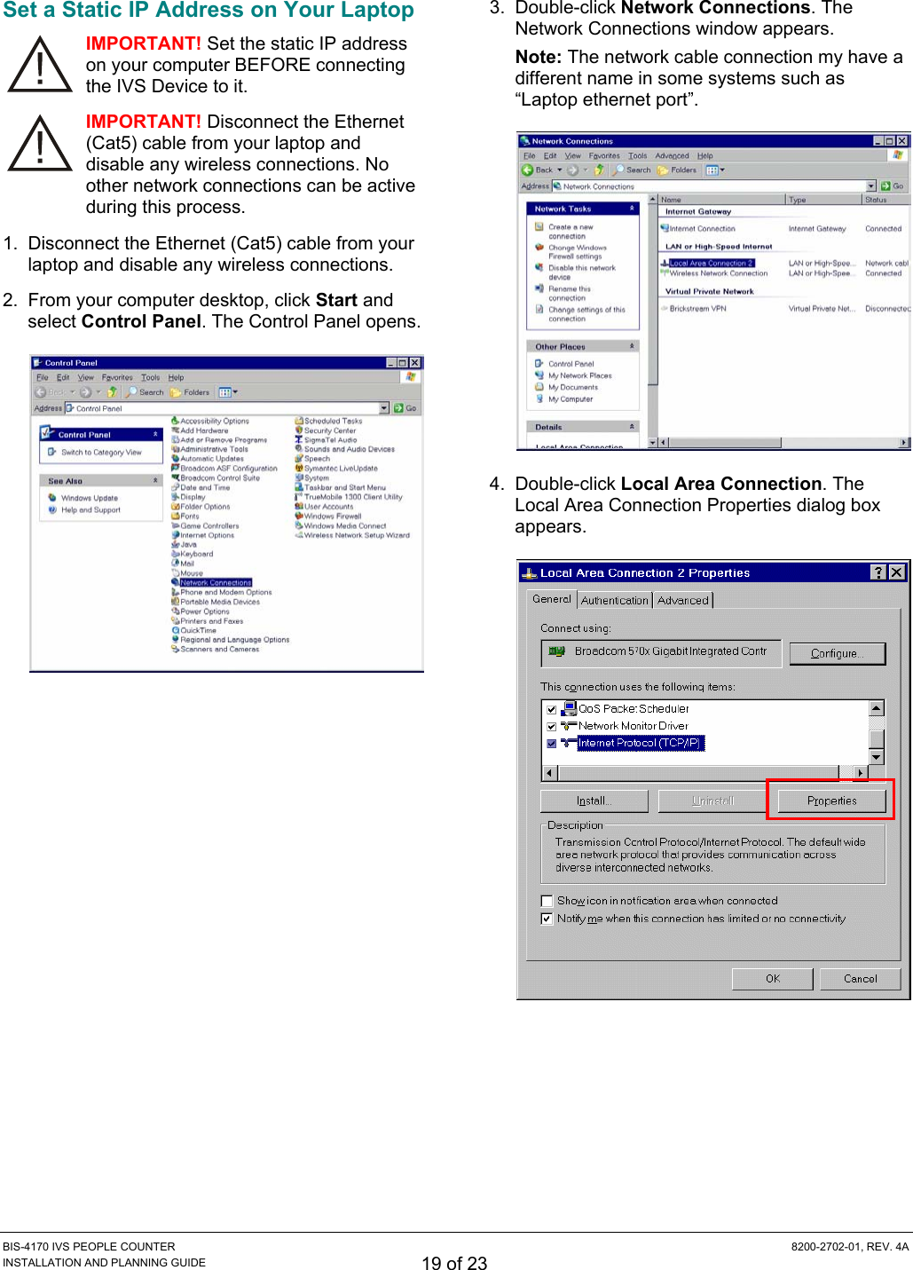
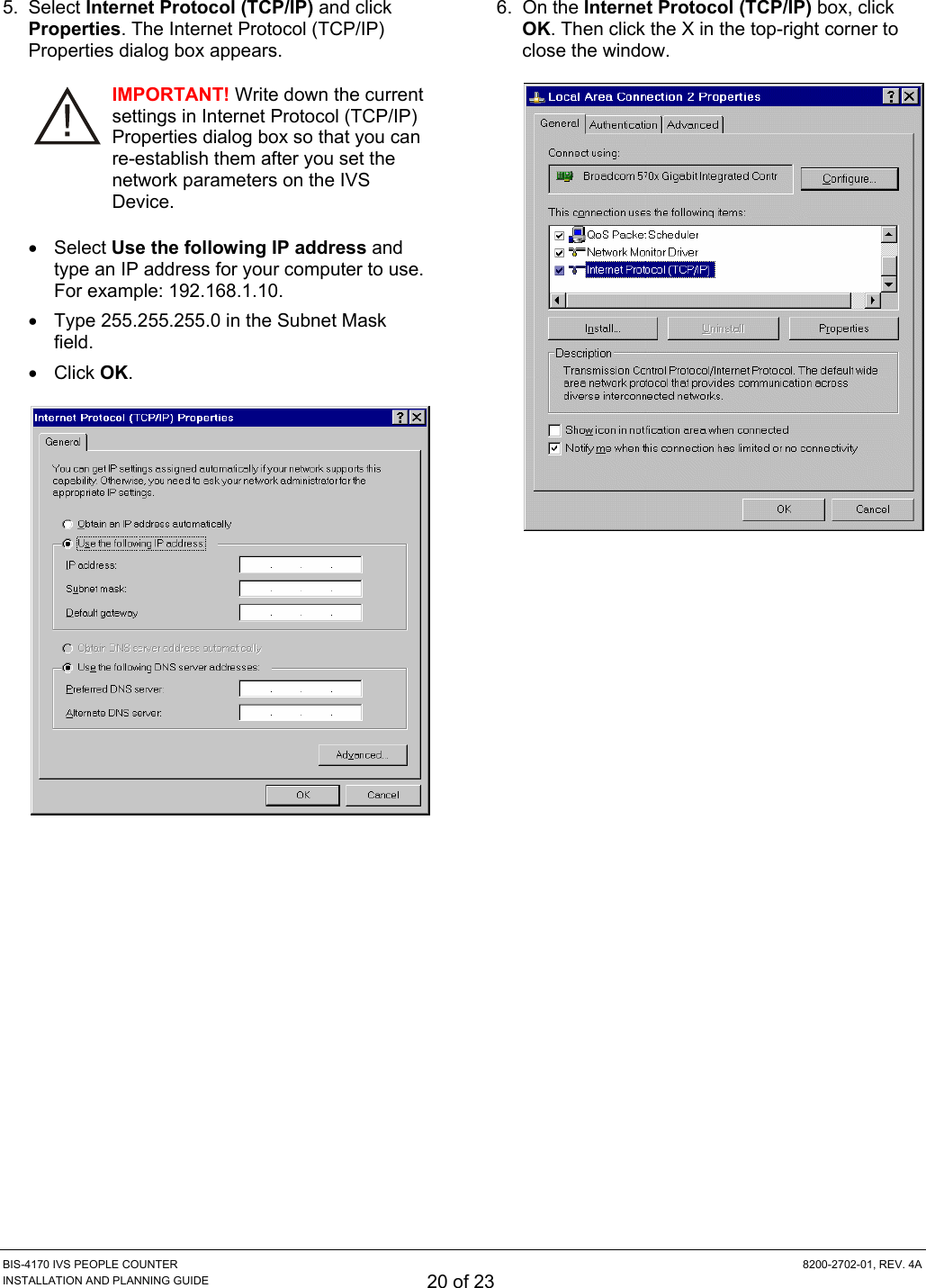
Users Manual
Navigation menu
Upload a User Manual
Namespaces
Wiki Guide
HTML
PDF
Info
Views
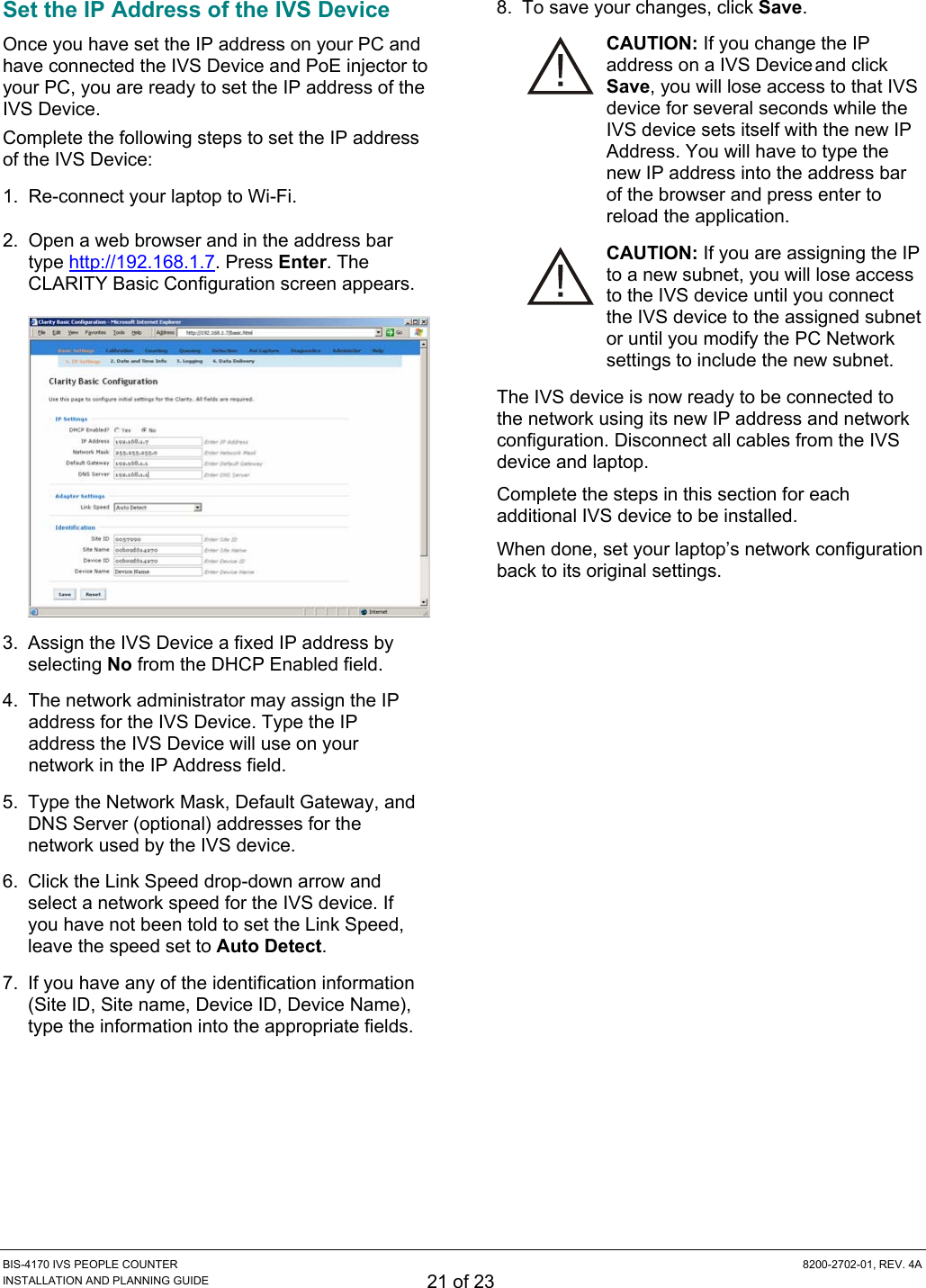
User Manual
Discussion / Help
Navigation