Tyco Safety Sensormatic BIC4170 Indoor Ceiling Mount Surveillance Transceiver User Manual
Tyco Safety Products/Sensormatic Indoor Ceiling Mount Surveillance Transceiver Users Manual
Users Manual

BIS-4170 IVS PEOPLE COUNTER 8200-2702-01, REV. 4A
INSTALLATION AND PLANNING GUIDE 1 of 23
BIS-4170
IVS People Counter
Installation and Planning Guide
For Mounting Heights: 2.4–4.3m (8–14ft)
To the Installer
WARNING! Install the people counter IVS device in an air space not used for environmental air. DO
NOT install the IVS device in a plenum or other environmental air-handling space.
For indoor use only.
Cables placed in environmental airspace must be plenum rated unless the cables are in raceways.
Contents
About the People Counter..................................... 2
Mounting Considerations....................................... 5
Installation Procedure............................................ 7
Running the Cables............................................ 8
Mounting the IVS Device ................................... 9
To a Ceiling Tile............................................ 10
To a Ceiling T-Bar......................................... 10
To a Wall....................................................... 11
To Wood or Sheetrock Ceilings.................... 12
Connecting Video, Communications,
and Power to the IVS Device ........................... 13
Verification Test ............................................... 15
Specifications ...................................................... 22
Declarations ........................................................ 22
Appendix A: Site Survey Form .......................... 23
© 2010 Sensormatic Electronics, LLC
!
BIS-4170 IVS PEOPLE COUNTER 8200-2702-01, REV. 4A
INSTALLATION AND PLANNING GUIDE 2 of 23
About the People Counter
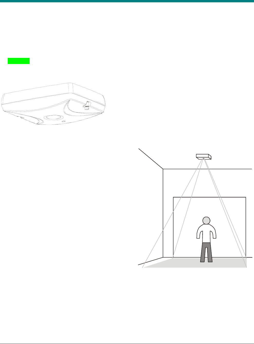
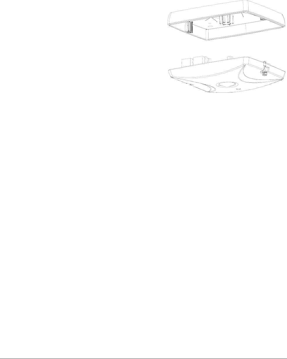
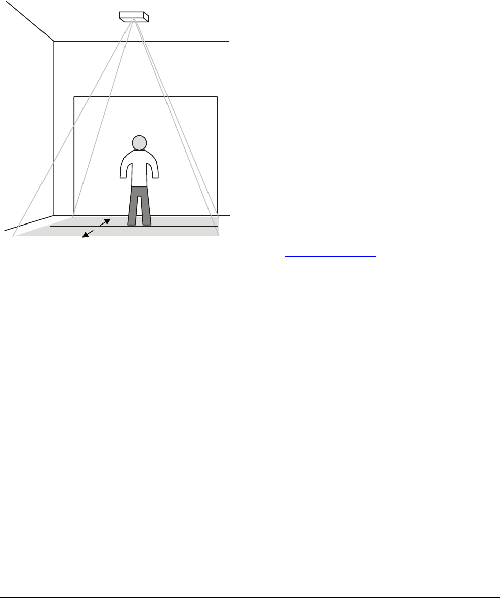
Mounted at ceiling heights up to 4.3m (14ft), the IVS People Counter device (Figure 1) tracks the paths of
people within its field-of-view (Figure 2). The IVS device can cover an entrance up to 2.4m (8ft). The IVS
device is also capable of reporting counts to a remote location through one of the following dedicated
communication interfaces:
• Ethernet
• LDM II via RS-485
• Bluetooth.
Figure 1. IVS device
Figure 2. IVS device field-of-view

BIS-4170 IVS PEOPLE COUNTER 8200-2702-01, REV. 4A
INSTALLATION AND PLANNING GUIDE 3 of 23
Coverage
Ceiling-mounted up to a height of 4.3m (14ft), the IVS device can cover a doorway or opening up to 2.4m (8ft)
wide.
The IVS device is powered by a 48Vdc Power over the Ethernet (PoE) device.
Tracking
A floor-facing camera in the IVS device is used to determine the height of a desired target (adults), and thus to
distinguish them from undesired targets such as shopping carts, pets, and children.
• A count line is projected across the entrance. The line is a virtual trip wire you draw on the video image
where the “feet” of the person tracked are to be counted.
• The count line can be set to trigger the count from a person crossing it while entering an area.
• A person entering an area is counted as one “enter”. A person exiting an area is counted as one “exit”.
• A personal computer is used to setup the IVS device and view what it detects. Downloaded or web-based
setup software displays the camera image.
BIS-4170 IVS PEOPLE COUNTER 8200-2702-01, REV. 4A
INSTALLATION AND PLANNING GUIDE 4 of 23
Figure 3. IVS device orientation
Hardware Features
BIS-4170 IVS PEOPLE COUNTER 8200-2702-01, REV. 4A
INSTALLATION AND PLANNING GUIDE 5 of 23
Mounting Considerations
Perform a site survey (Appendix A) while observing the installation site for the following considerations.
Ceiling Considerations
• Composition: Sheet rock, plaster, suspended ceiling.
The IVS device can attach to any 1/4-20 thread-per-inch bolt of a customer mounting bracket.
• Height: The IVS device can be mounted up to a height of 4.3m (14ft).
CAUTION: The tilt of the IVS device should follow the slope of the floor. The setup software can
adjust IVS device settings for unavoidable tilt, as long as it is less than 10 degrees of the floor
slope (placeholder, TBD).
CAUTION: Mounting over stairs or highly sloped floors is not recommended (placeholder, TBD).
• Access: Check for in-ceiling obstacles such as ceiling vents and fire sprinklers.
• Location: Mount the IVS device in such a way that its field-of-view is centered over the entry/exit corridor.
Also, do not mount the IVS device to capture people through glass or other translucent surfaces
(placeholder, TBD).

BIS-4170 IVS PEOPLE COUNTER 8200-2702-01, REV. 4A
INSTALLATION AND PLANNING GUIDE 6 of 23
Traffic Corral Points
Check for walls, displays and anti-theft pedestals that help corral traffic. Ideally, the traffic path should be
elongated as much as possible under the IVS device.
PoE Device
The PoE device supplied with the IVS device is typically placed in computer wiring room or next to the IVS
device near a convenient power outlet. The PoE comes with a 1.8m (6ft) power cable.
Other Considerations
• 24-hour or timed power available.
• Cable distance from IVS device to computer wiring room: DO NOT exceed a maximum of 100m (330ft).
• Network switch type and ports available.

BIS-4170 IVS PEOPLE COUNTER 8200-2702-01, REV. 4A
INSTALLATION AND PLANNING GUIDE 7 of 23
Installation Procedure
Parts Required
• DVR for verification testing (The DVR records video data “seen” by the IVS device.)
• Cat5 cable
• IVS device
• ¼-20 threaded rod
• ¼-20 nuts (2)
Optional Parts*
?
BIS-4170 IVS PEOPLE COUNTER 8200-2702-01, REV. 4A
INSTALLATION AND PLANNING GUIDE 8 of 23
Running the Cables
Run a Cat5 cable from the installation site for the IVS device to the installation site for the PoE. Run another
cable from the PoE to the store’s computer wiring room.
Note: Cat5 cable runs cannot exceed 100m (330ft) without using a repeater. Terminate cables following Error!
Reference source not found. below.
• Use plenum / non-plenum cable per local requirements.
• Use pre-manufactured patch cables when available.
• Leave a sufficient service loop at end of each home run.
• Test all cables. Most on-site issues are cable related.
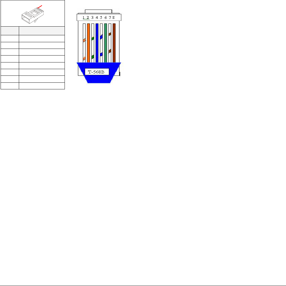
Table 1. Ethernet cable pin assignments
Pin Wire Color
1 WHT / ORG
2 ORG
3 WHT / GRN
4 BLU
5 WHT / BLU
6 GRN
7 WHT / BRN
8 BRN
Note: Male plug pin assignments are according to the T-568B standard. All connections are “straight through” from plug to
plug, that is: pin 1 to pin 1, pin 2 to pin 2, and so on.
Pin 1

BIS-4170 IVS PEOPLE COUNTER 8200-2702-01, REV. 4A
INSTALLATION AND PLANNING GUIDE 9 of 23
Mounting the IVS Device
The IVS device can be installed at heights up to 4.3m (14ft) using one of the following methods: surface
mounting bracket or recessed mounting bracket.
WARNING! Install the IVS device in an air space not used for environmental air. DO NOT install in a
plenum or other environmental air-handling space.
WARNING! The ceiling must support up to 5.1kg (11.2 lbs). If the ceiling cannot support the IVS
device, ask building maintenance to install additional ceiling supports
WARNING! The IVS device can mount to wood or drywall ceilings with minimal disturbance to the
ceiling. It can also mount to grid ceiling structure but not to the removable tile itself
Tested to IEC 60950-1.
CAUTION: Double check all IVS device locations before drilling or cutting ceiling. This is especially
important for multiple IVS devices
Parts Supplied
Customer to supply 1/4-20 threaded rod, two 1/4-20 nuts, 2x4 wood brace, and tile hold-down clips.
!
!
!
BIS-4170 IVS PEOPLE COUNTER 8200-2702-01, REV. 4A
INSTALLATION AND PLANNING GUIDE 10 of 23
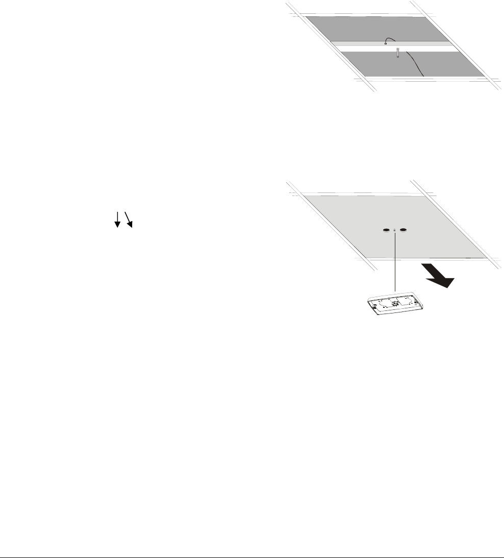
To a Ceiling Tile
1. Do the following to prepare the tile (Figure ):
• Remove the ceiling tile and drill a ¼-inch hole in its center.
• Cut a 2.5ft piece of wood 2x4 and drill a ¼-inch hole in its center.
• Center the 2x4 above the tile structure. Then place the ¼-20 threaded rod though the hole and secure it
from above and below with two ¼-20 nuts. Ensure the rod extends only about ¼-inch below the tile.
• Reinsert the ceiling tile with the threaded rod protruding through the hole in the tile.
2. Do the following to attach the IVS device (Figure ):
• Loosen the two bottom screws in the IVS device and remove its top shell.
• Thread the top shell to the threaded rod until it is secure against the tile.
• From the underside of the tile, punch a cable access hole in the tile above the opening(s) in the top shell.
3. Run the video cable from the DVR, above the tile ceiling, and through the opening in the top shell.
4. Push the end of the Cat5 and pigtail cables down through the openings in the top shell.
To a Ceiling T-Bar
Mounting brackets enable the IVS device to mount to a suspended ceiling T-bar.
Additional Parts Required
• Mounting Brackets (2): 0500-7193-01
• Screws, Pan head, M3x8 (2): 5801-1051-120
Procedure
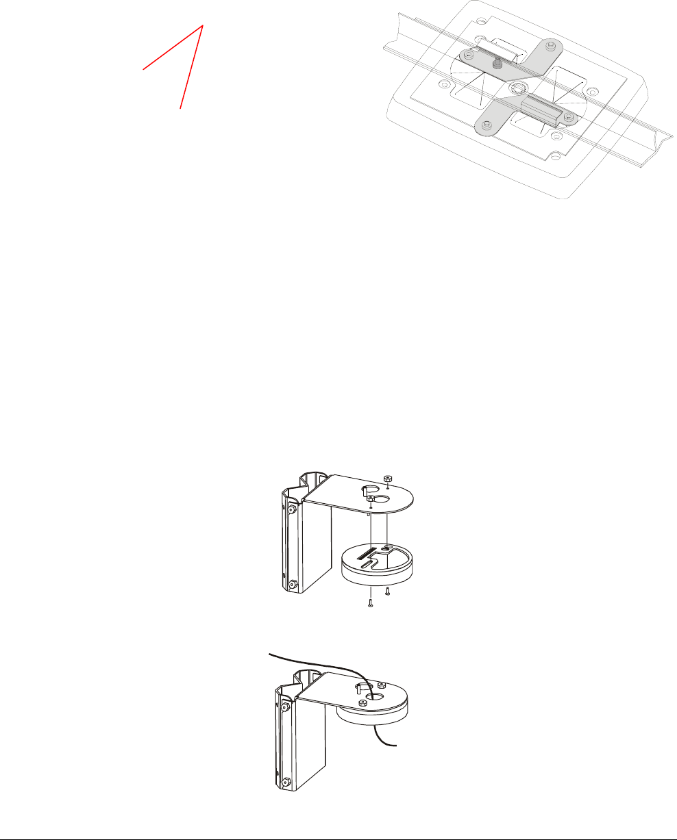
1. Loosen the two bottom screws in the IVS device and remove its top shell.
2. Cut a triangular piece off of the rubber flap to keep it from interfering with the locking screw. Repeat for the
other locking screw (Figure ).
Traffic Direction
Cable Access
IVS Device
BIS-4170 IVS PEOPLE COUNTER 8200-2702-01, REV. 4A
INSTALLATION AND PLANNING GUIDE 11 of 23
3. Attach two mounting brackets to the outside of the top shell with two screws as shown.
4. Maneuver the brackets into place, then tighten the two locking crews from below to secure the top shell to
the T-bar.
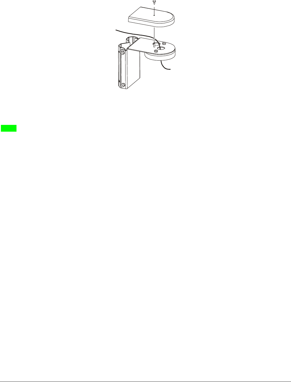
To a Wall
The RHIUCM wall mounting bracket enables the IVS device to mount to a wall.
Additional Parts Required
RHIUCM wall mounting bracket (1)
1. Loosen the two bottom screws in the IVS device and remove its top shell.
2. Mount the RHIUCM wall mount bracket supplied to the wall surface (see instructions supplied with the
bracket).
3. Place the top shell against the bracket.
4. Screws and nuts are provided for attachment. Place the top shell against the bracket and, from underneath,
insert the two screws through the holes and secure them with the nuts.
5. Run the Cat5 cable through the hole in the top of the bracket.
Locking Screws (2)
BIS-4170 IVS PEOPLE COUNTER 8200-2702-01, REV. 4A
INSTALLATION AND PLANNING GUIDE 12 of 23
6. Attach the cover to the bracket/counter assembly.
To Wood or Sheetrock Ceilings
(TBD)
BIS-4170 IVS PEOPLE COUNTER 8200-2702-01, REV. 4A
INSTALLATION AND PLANNING GUIDE 13 of 23
Connecting Video, Communications, and Power to the IVS Device
The PoE can be placed in the computer room (where power is readily accessible) as long as cable length from
the PoE to the IVS Device does not exceed 100m (330ft). The minimum cable length is 0.5m.
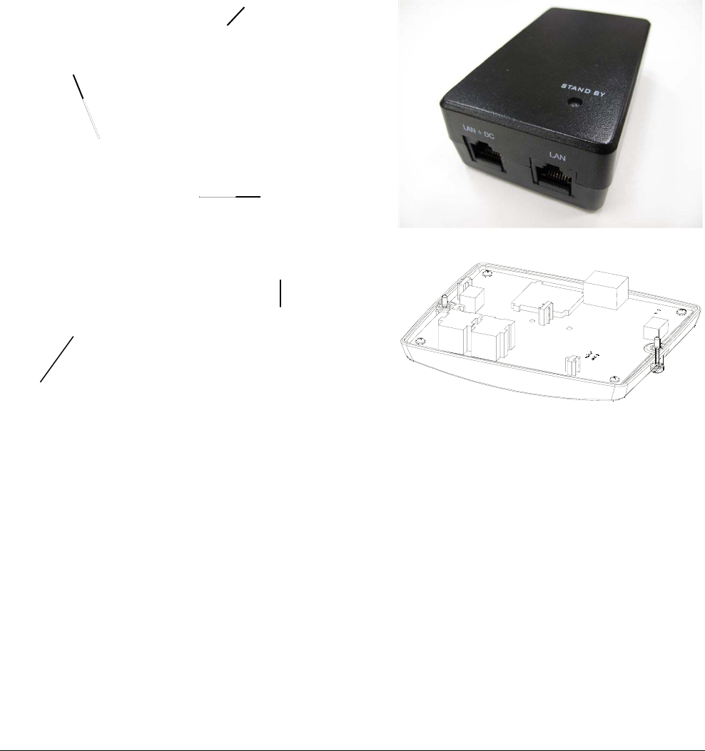
1. Connect the following cables (Figure 4):
a. Connect a Cat5 cable between the host computer and the LAN input on the PoE.
b. Connect a Cat5 cable between the PoE Injector “LAN+DC” port (power and communications) and the
Ethernet connector J1 in the IVS device.
Figure 4. Connecting the PoE to the IVS Device
Video Out E1, E2
Ethernet Port J1
Power/Status LED
LAN + DC
(to IVS)
LAN
(to Host)
AC in
BIS-4170 IVS PEOPLE COUNTER 8200-2702-01, REV. 4A
INSTALLATION AND PLANNING GUIDE 14 of 23
2. For Video to the DVR, plug the pigtail connector of the DVR video cable to connectors E1 and E2 inside
the IVS Device.
3. Attach the bottom shell to the top shell. Tighten both screws securely.
4. Once the PoE injector into a 24-hour outlet, the IVS device will begin its boot up process. This process
takes about 40 seconds, where the Power/Status LED on the PoE module momentarily turns yellow (stand
by), then green indicating that the PoE has successfully identified the IVS as a PoE compliant device.
BIS-4170 IVS PEOPLE COUNTER 8200-2702-01, REV. 4A
INSTALLATION AND PLANNING GUIDE 15 of 23
Verification Test
1. Check out the entire ‘IVS Engineering Test Tool Setup’ folder
from StarTeam. Locate the ‘IVS Engineering Test Tool’ icon
on the desktop of your laptop.
The Test Tool is used to perform initial installation of the IVS
and can be used to verify count information obtained from the
IVS Device. Communications will occur via one of two
communications media: Ethernet or Bluetooth (selectable via
a pull down menu).
The IVS Engineering Test Tool can:
• Display the static video image “seen” by the IVS Device
• Be used to draw count lines
• Transmit count lines to the DSP
• Be used to set and maintain time
• Display and storing count data.
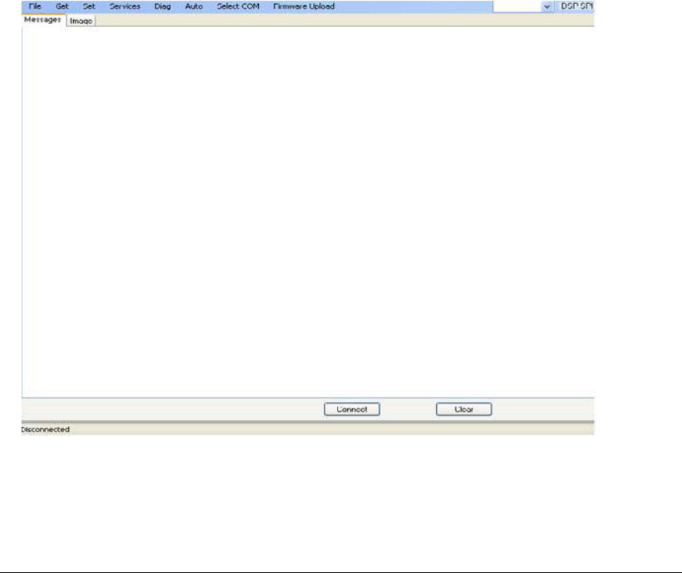
2. On your laptop, click the icon to open the IVS Engineering
Test Tool.
BIS-4170 IVS PEOPLE COUNTER 8200-2702-01, REV. 4A
INSTALLATION AND PLANNING GUIDE 16 of 23
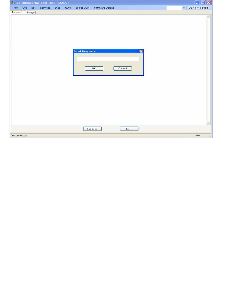
3. From the pull down menu ‘Select COM’, select ‘Configure’ to
invoke the following ‘Input Requested’ dialog box. Enter the
IP address for the IVS Device and click OK.
4. Connect a Cat5 cable from the PoE Injector “LAN” port to the
Ethernet port on your laptop.
5. From the ‘Select COM’ pull down menu, select ‘TCP/IP’. At
the bottom of the screen, click ‘Connect’.
6. Verify that the addressed IVS Device is ‘Connected’ to the
IVS Engineering Test Tool.
BIS-4170 IVS PEOPLE COUNTER 8200-2702-01, REV. 4A
INSTALLATION AND PLANNING GUIDE 17 of 23
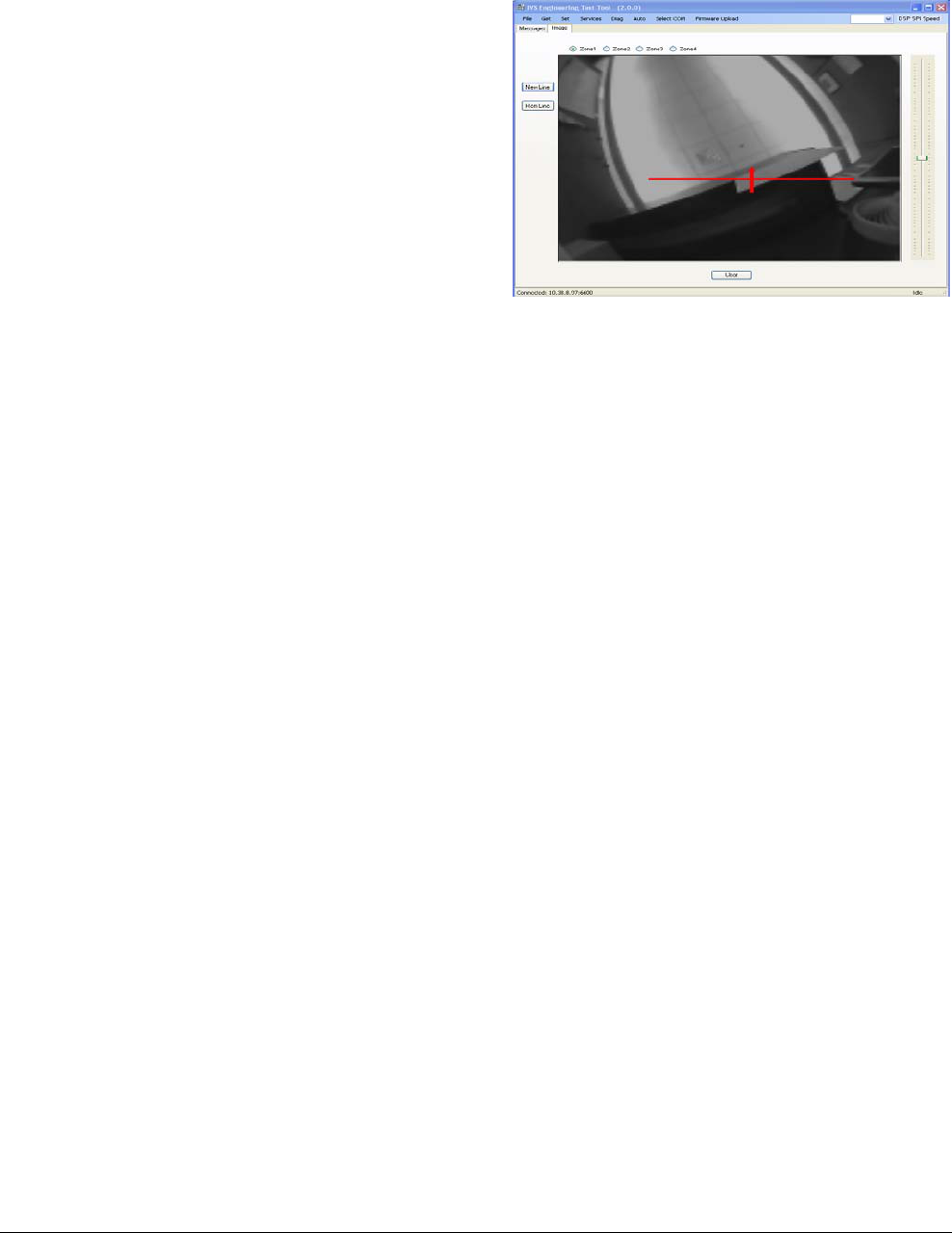
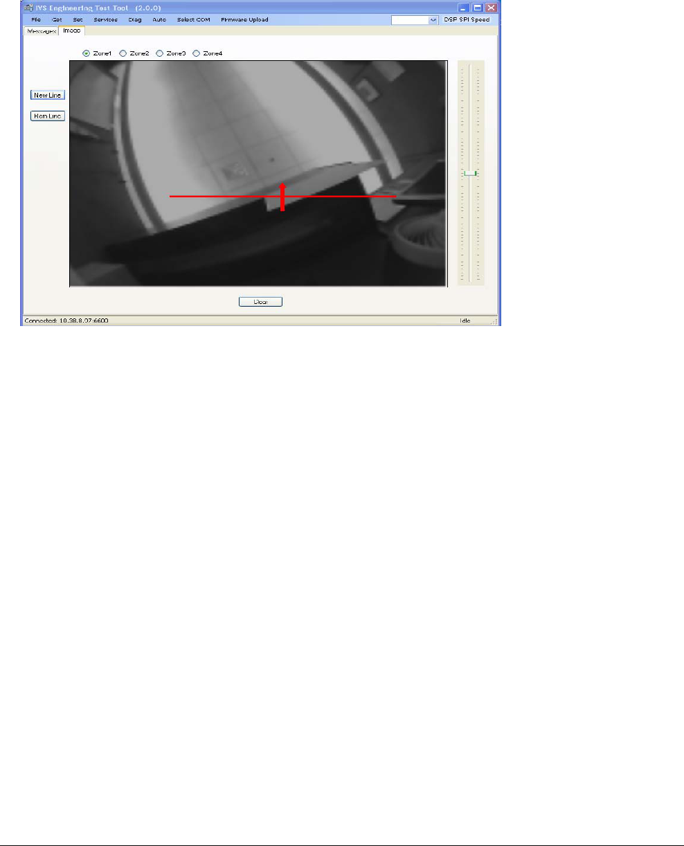
7. On the side panel of the Test Tool, select the ‘Image’ tab.
Then from the ‘Get’ pull down menu, select ‘Image’. Verify on
the DVR screen that the IVS Device is capturing and
processing the video image.
8. Verify that the image on your display corresponds to the
image “seen” by the IVS device.
9. Select ‘New Line’ from the side panel of the Test Tool. Select
the line color from color palette and click OK.
10. Using the mouse, position the cursor to indicate the start of
the line, drag it to the desired destination point, then click the
cursor again. An arrow indicates the traffic direction.
• Dragging the line left to right produces an UP arrow.
• Dragging the line right to left produces a DOWN arrow.
• Traffic crossing the line in the direction of the arrow would
trigger ‘IN’ counts.
• Traffic crossing the line in the direction opposite the arrow
would trigger “OUT’ counts.
11. From the ‘Diag’ pull down menu, select ‘Verification Test’ to
invoke an ‘Open’ dialog box to save the count data to a .txt
file. Name and save file for later retrieval.
Note: A ‘Test In Progress’ indication at the bottom right of the
Test Tool appears as shown below.
12. After the prescribed count intervals, terminate the verification
test by clicking ‘Disconnect’ at the bottom of the Test Tool.
13. Retrieve .txt file for count verification against the DVR
captured events.
BIS-4170 IVS PEOPLE COUNTER 8200-2702-01, REV. 4A
INSTALLATION AND PLANNING GUIDE 18 of 23
Adjusting the Count Line
The IVS device automatically sets the count line at
the middle of its field-of-view. However, in certain
situations, the line may have to be moved forward
or backward.
To move the count line, do the following:
Setting the IP Address for the IVS
Device
Auto addressing
Each IVS Device is automatically assigned a Static
IP address of 198.168.0.1.
The best method is to disconnect all network
connections from your laptop, manually assign it an
IP address (such as 192.168.1.10), and then
connect it directly to the IVS Device. Then each
IVS Device can be assigned a unique address
such as 192.168.1.7 for IVS Device 1, 192.168.1.8
for IVS Device 2, and 192.168.1.9 for IVS Device
3.
In this section, you will:
• Set a static IP address on your laptop
• Connect a IVS Device to your laptop
• Set the IP address for the IVS Device.
Laptop Requirements
The following is required to run IVS software.
• Use Microsoft® IE6+ or Mozilla® Firefox® 3+ web
browser.
• Java Runtime JRE 1.6 update 10
(http://www.java.com). Required to view live
video.
BIS-4170 IVS PEOPLE COUNTER 8200-2702-01, REV. 4A
INSTALLATION AND PLANNING GUIDE 19 of 23
Set a Static IP Address on Your Laptop
IMPORTANT! Set the static IP address
on your computer BEFORE connecting
the IVS Device to it.
IMPORTANT! Disconnect the Ethernet
(Cat5) cable from your laptop and
disable any wireless connections. No
other network connections can be active
during this process.
1. Disconnect the Ethernet (Cat5) cable from your
laptop and disable any wireless connections.
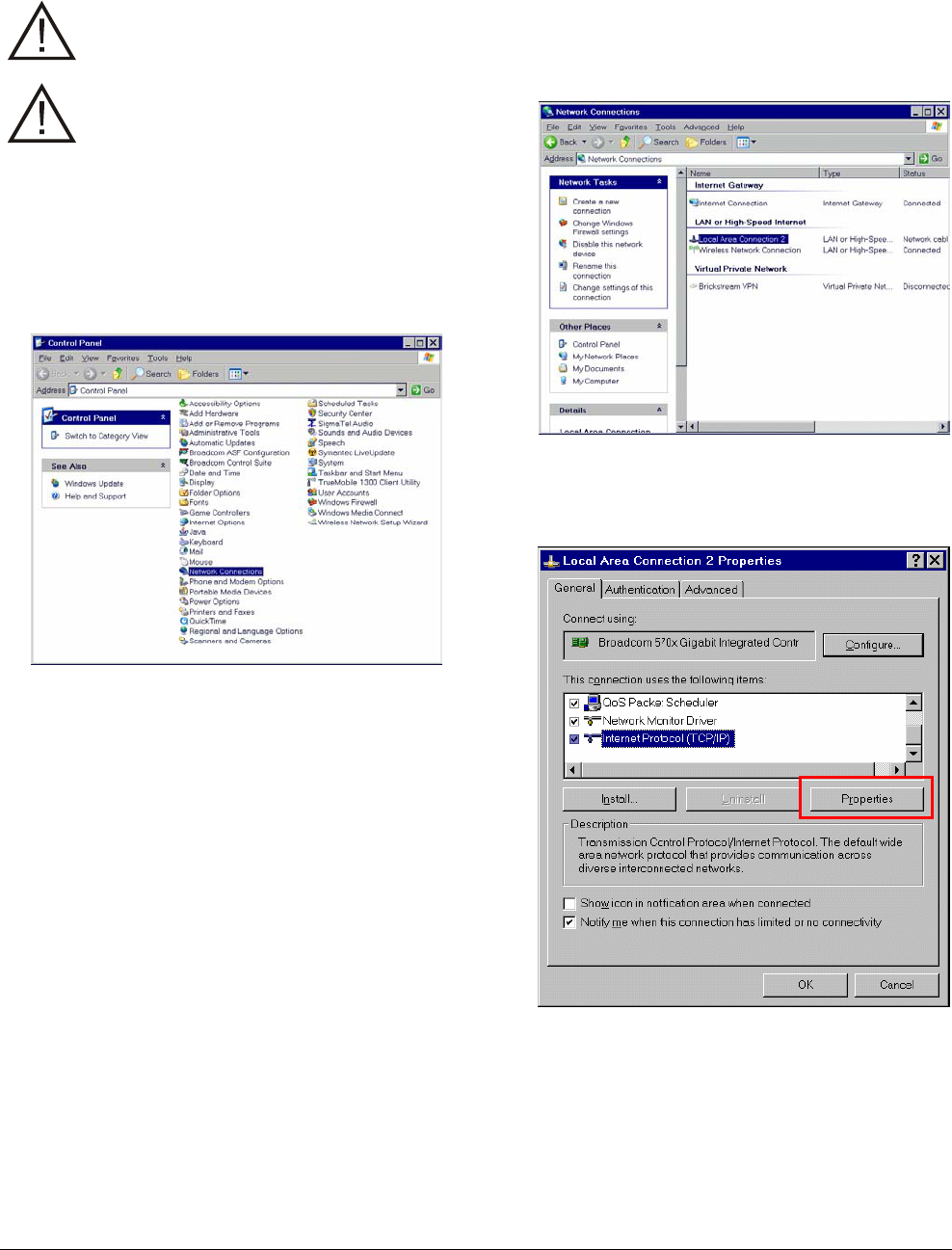
2. From your computer desktop, click Start and
select Control Panel. The Control Panel opens.
3. Double-click Network Connections. The
Network Connections window appears.
Note: The network cable connection my have a
different name in some systems such as
“Laptop ethernet port”.
4. Double-click Local Area Connection. The
Local Area Connection Properties dialog box
appears.
BIS-4170 IVS PEOPLE COUNTER 8200-2702-01, REV. 4A
INSTALLATION AND PLANNING GUIDE 20 of 23
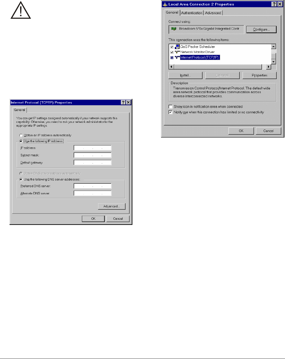
5. Select Internet Protocol (TCP/IP) and click
Properties. The Internet Protocol (TCP/IP)
Properties dialog box appears.
IMPORTANT! Write down the current
settings in Internet Protocol (TCP/IP)
Properties dialog box so that you can
re-establish them after you set the
network parameters on the IVS
Device.
• Select Use the following IP address and
type an IP address for your computer to use.
For example: 192.168.1.10.
• Type 255.255.255.0 in the Subnet Mask
field.
• Click OK.
6. On the Internet Protocol (TCP/IP) box, click
OK. Then click the X in the top-right corner to
close the window.
BIS-4170 IVS PEOPLE COUNTER 8200-2702-01, REV. 4A
INSTALLATION AND PLANNING GUIDE 21 of 23
Set the IP Address of the IVS Device
Once you have set the IP address on your PC and
have connected the IVS Device and PoE injector to
your PC, you are ready to set the IP address of the
IVS Device.
Complete the following steps to set the IP address
of the IVS Device:
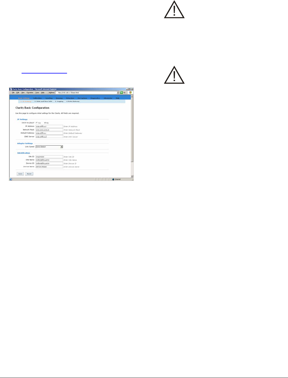
1. Re-connect your laptop to Wi-Fi.
2. Open a web browser and in the address bar
type http://192.168.1.7. Press Enter. The
CLARITY Basic Configuration screen appears.
3. Assign the IVS Device a fixed IP address by
selecting No from the DHCP Enabled field.
4. The network administrator may assign the IP
address for the IVS Device. Type the IP
address the IVS Device will use on your
network in the IP Address field.
5. Type the Network Mask, Default Gateway, and
DNS Server (optional) addresses for the
network used by the IVS device.
6. Click the Link Speed drop-down arrow and
select a network speed for the IVS device. If
you have not been told to set the Link Speed,
leave the speed set to Auto Detect.
7. If you have any of the identification information
(Site ID, Site name, Device ID, Device Name),
type the information into the appropriate fields.
8. To save your changes, click Save.
CAUTION: If you change the IP
address on a IVS Device and click
Save, you will lose access to that IVS
device for several seconds while the
IVS device sets itself with the new IP
Address. You will have to type the
new IP address into the address bar
of the browser and press enter to
reload the application.
CAUTION: If you are assigning the IP
to a new subnet, you will lose access
to the IVS device until you connect
the IVS device to the assigned subnet
or until you modify the PC Network
settings to include the new subnet.
The IVS device is now ready to be connected to
the network using its new IP address and network
configuration. Disconnect all cables from the IVS
device and laptop.
Complete the steps in this section for each
additional IVS device to be installed.
When done, set your laptop’s network configuration
back to its original settings.

BIS-4170 IVS PEOPLE COUNTER 8200-2702-01, REV. 4A
INSTALLATION AND PLANNING GUIDE 22 of 23
Specifications
Electrical
Primary Input ................................................ 48Vdc, 0.5A
Power consumption .......................................... 14W Max
Certified Limited Power Source
Network
Cabling ......................................................... Category 5e
Ethernet ................. Dual channel 100Mb Ethernet switch
Power .............................................. IEEE 802.3af Power
Addressing........................................... DHCP or Static IP
Environmental
Operating Temperature: ...........0° to 45°C (32° to 113°F)
Enclosure.....................................................IP20 Nema 1
Mechanical
Dimensions............................... 64mm x 155mm x 33mm
(2.5in x 6.1in x 1.3in)
Lens.......................................................................2.0mm
Enclosure material ................................................. Plastic
Weight ....................................................0.23kg (0.5 lbs.)
Declarations
Regulatory Compliance
EMC ....................................................... 47 CFR, Part 15
FCC COMPLIANCE: This equipment complies with Part 15
of the FCC rules for Class A digital devices when installed and
used in accordance with the instruction manual. Following
these rules provides reasonable protection against harmful
interference from equipment operated in a commercial area.
This equipment should not be installed in a residential area as
it can radiate radio frequency energy that could interfere with
radio communications, a situation the user would have to fix at
their own expense.
CANADIAN COMPLIANCE: This Class A digital apparatus
complies with Canadian ICES-003. Cet appareil numérique de
la classe A est conforme à la norme NMB-003 du Canada.
EQUIPMENT MODIFICATION CAUTION: Equipment
changes or modifications not expressly approved by
Sensormatic Electronics Corporation, the party responsible for
FCC compliance, could void the user's authority to operate the
equipment and could create a hazardous condition.
Other Declarations
WARRANTY DISCLAIMER: Sensormatic Electronics
Corporation makes no representation or warranty with respect
to the contents hereof and specifically disclaims any implied
warranties of merchantability or fitness for any particular
purpose. Further, Sensormatic Electronics Corporation
reserves the right to revise this publication and make changes
from time to time in the content hereof without obligation of
Sensormatic Electronics Corporation to notify any person of
such revision or changes.
LIMITED RIGHTS NOTICE: For units of the Department
of Defense, all documentation and manuals were developed at
private expense and no part of it was developed using
Government Funds. The restrictions governing the use and
disclosure of technical data marked with this legend are set
forth in the definition of “limited rights” in paragraph (a) (15)
of the clause of DFARS 252.227.7013. Unpublished - rights
reserved under the Copyright Laws of the United States.
TRADEMARK NOTICE: Sensormatic is a registered
trademark of Sensormatic Electronics Corporation. The SD
Logo (below) is a trademark of SD-3C, LLC. Other product
names mentioned herein may be trademarks or registered
trademarks of Sensormatic or other companies.
No part of this guide may be reproduced in any form without
written permission from Sensormatic Electronics Corporation.
MDR 2/2010

BIS-4170 IVS PEOPLE COUNTER 8200-2702-01, REV. 4A
INSTALLATION AND PLANNING GUIDE 23 of 23
Appendix A: Site Survey Form
General Information
Customer Name
Site Name and Number
Site Address
Site Telephone Number
Mon Tue Wed
Hours Of Operation Thu Fri Sat Sun
Local Contact Name
Contact Telephone
Survey Performed By
Survey Date and Time
Ceiling Information
Ceiling Height IVS Device Mounting
Height
Ceiling Composition Ceiling Slope
Ceiling Access
Additional Considerations
Door Information
Door Width Door Type
Pedestals (yes/no)
Additional Considerations
Other Information
Floor Slope Distance to Head End
Head-End Power? Ceiling Power?
Network Switch Type Num. Ports Available
Sketch