Tyco Safety Sensormatic BIX1000 Business Intelligence Module User Manual REV
Tyco Safety Products/Sensormatic Business Intelligence Module REV
Contents
- 1. User manual
- 2. User manual_REV
User manual_REV
PRELIMINARY
WIRELESS DEVICE MODULE (BIX1000) 8200-1088-15, REV 3D
INSTALLATION GUIDE 1 of 16 *8200-1088-15*
Wireless Device Module (BIX1000)
Installation Guide
BIX1000
© 2018 Sensormatic Electronics, LLC

PRELIMINARY
WIRELESS DEVICE MODULE (BIX1000) 8200-1088-15, REV 3D
INSTALLATION GUIDE 2 of 16 *8200-1088-15*
Contents
About this guide .................................................................................................................................................. 3
Additional documentation .............................................................................................................................. 3
Technical Support ......................................................................................................................................... 3
Training ......................................................................................................................................................... 3
About the product ............................................................................................................................................... 4
Features ........................................................................................................................................................ 4
Compatibility .................................................................................................................................................. 5
Cable kit numbers ......................................................................................................................................... 5
Tool requirements ......................................................................................................................................... 6
Section I: Before you begin ................................................................................................................................ 6
System requirements ....................................................................................................................................... 6
Firmware requirements ................................................................................................................................. 6
Laptop requirements ..................................................................................................................................... 6
Wiring requirements ...................................................................................................................................... 6
Safety ................................................................................................................................................................. 7
Installation prerequisites ................................................................................................................................. 7
Section II: Installation sequence overview ......................................................................................................... 8
Section III: Installing the BIX1000 ...................................................................................................................... 9
Overview of steps ............................................................................................................................................. 9
Step 1: Connecting the BIX1000 cable to the EAS device ........................................................................... 9
Step 2: Commissioning the BIX1000 .............................................................................................................. 9
Step 3: Locating the BIX1000 ........................................................................................................................ 11
Specifications ................................................................................................................................................... 14
Declarations ..................................................................................................................................................... 15
Other declarations .......................................................................................................................................... 16

PRELIMINARY
WIRELESS DEVICE MODULE (BIX1000) 8200-1088-15, REV 3D
INSTALLATION GUIDE 3 of 16 *8200-1088-15*
About this guide
This installation guide explains how to install the Wireless Device Module (BIX1000), with the Wireless Device
Manager (BIM1000), to synchronize and aggregate data from all Sensormatic-connected devices.
Additional documentation
The following is a list of additional documents related to this installation:
• Wireless Device Manager (BIM1000) Installation Guide, 8200-1088-03.
• Wireless Device Manager (BIM1000) and Wireless Device Module (BIX1000) Setup Guide, 8200-1088-01.
• Ultra Post® IV AMS-1012 Wireless Device Module (BIX1000) Cable Kit Installation Guide, 8200-1088-05.
• Ultra Post® VI AMS-1014 Wireless Device Module (BIX1000) Cable Kit Installation Guide, 8200-1088-06.
• Ultra 1.8 Meter ABS Pedestal Wireless Device Module (BIX1000) Cable Kit Installation Guide,
8200-1088-07.
• AMB9010-IPS and AMB-1200 Label Deactivator Controller Wireless Device Module (BIX1000) Cable Kit
Installation Guide, 8200-1088-08.
• AMS-9050 Controller Wireless Device Module (BIX1000) Cable Kit Installation Guide, 8200-1088-09.
• AMS-9040 Controller Wireless Device Module (BIX1000) Cable Kit Installation Guide, 8200-1088-10.
• AMS-9060 Controller and AMS-1170-2C/4C Controller Wireless Device Module (BIX1000) Cable Kit
Installation Guide, 8200-1088-11.
• ZBSMPROE ScanMax® Pro Label Deactivator Controller Wireless Device Module (BIX1000) Cable Kit
Installation Guide, 8200-1088-12.
• IDKM-10XX/AMK-10XX SuperTag® Detacher Wireless Device Module (BIX1000) Cable Kit Installation
Guide, 8200-1088-13.
• AMB-2011/AMB-1101/ZBAMB9010 EAS Label Deactivator Wireless Device Module (BIX1000) Cable Kit
Installation Guide, 8200-1088-16.
• Wireless Device Module (BIX1000) Extension Cable Kit Installation Guide, 8200-1088-14.
• AMS-1080 Controller Wireless Device Module (BIX1000) Cable Kit Installation Guide, 8200-1088-17.
Technical Support
For product bulletins, and the most recent updates to this guide, visit https://sensormaticsecurelogin.com
Training
WARNING: Do not install a Wireless Device Module (BIX1000) unless you have completed the following
Wireless Device Manager (BIM/BIX) Training Curriculum modules:
• BIM and BIX Installation Technical Training.
• BIM Configuration Technical Training.
• Optional: SMaaS Overview Sales Training.
PRELIMINARY
WIRELESS DEVICE MODULE (BIX1000) 8200-1088-15, REV 3D
INSTALLATION GUIDE 4 of 16 *8200-1088-15*
About the product
The Wireless Device Manager (BIM1000) is a wireless access point that uses an IEEE 802.15.4 wireless
standard to connect to the Wireless Device Module (BIX1000).
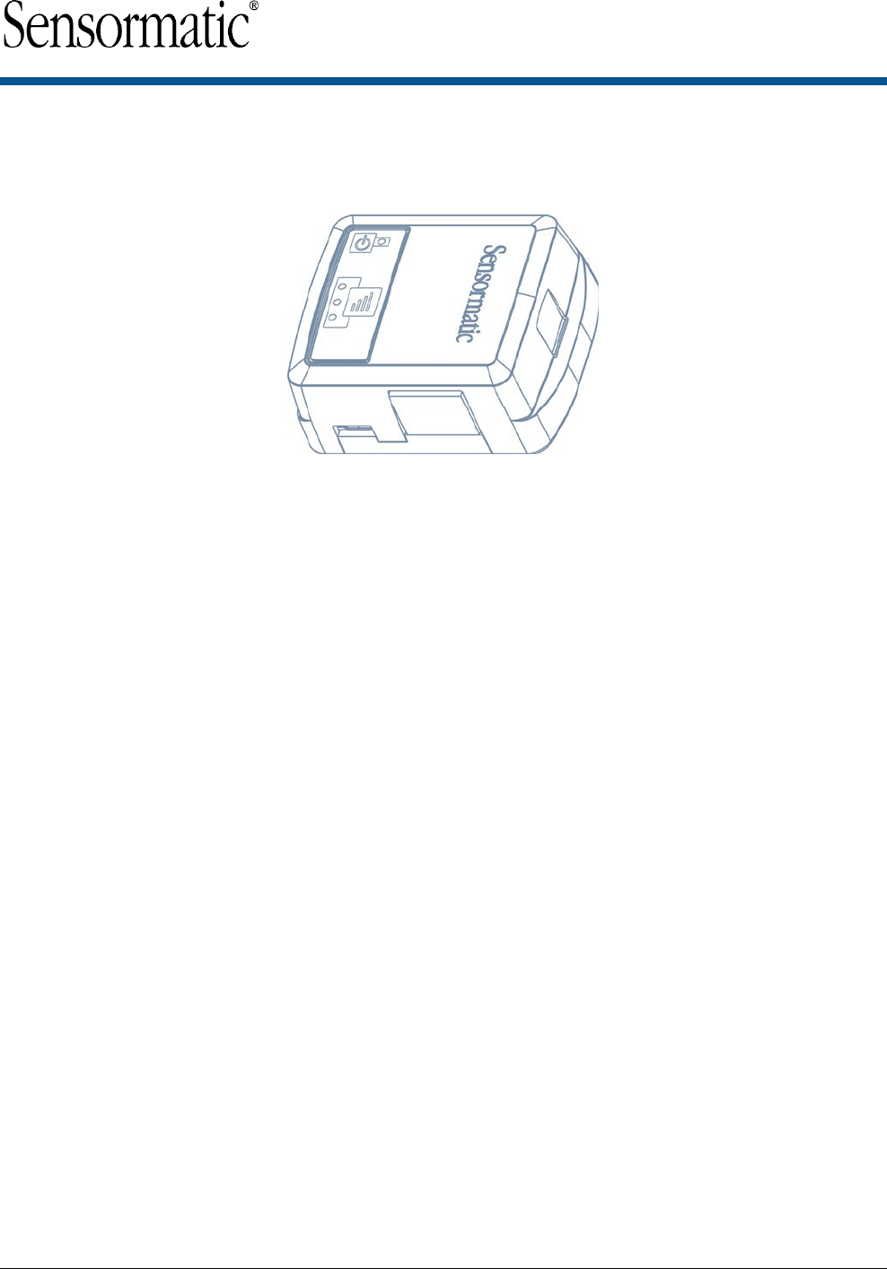
The Wireless Device Module (BIX1000), as shown in Figure 1, uses the IEEE 802.15.4 wireless protocol to
connect to the Wireless Device Manager (BIM1000) to synchronize all in-store Sensormatic-connected
deactivation and detection controllers, to collect data and to provide a health status for all the connected
devices.
The synchronization between the deactivation and the detection controllers minimizes failed deactivation at the
Point-of-Sale (POS) and nuisance alarms at the store exit area. The data collected includes alarms, events,
and people-counting statistics. It also collects alarm input responses through an Android tablet device.
Customers can use a desktop browser to log into a TrueVUE reporting platform, or a Shrink Management as a
Service (SMaaS) platform, to access historical daily data reports from all the connected devices. The customer
can also use an Android tablet device for alarm input responses.
Important: You must install the Wireless Device Manager (BIM1000) before you install the Wireless Device
Module (BIX1000).
Features
The Wireless Device Module (BIX1000) has the following features:
• It is auto-discovered by the BIM1000 after commissioning.
• It uses the wireless IEEE 802.15.4 Standard for communications.
• It has external LED status and signal strength indicators.
• It has Micro USB Type B access for commissioning.
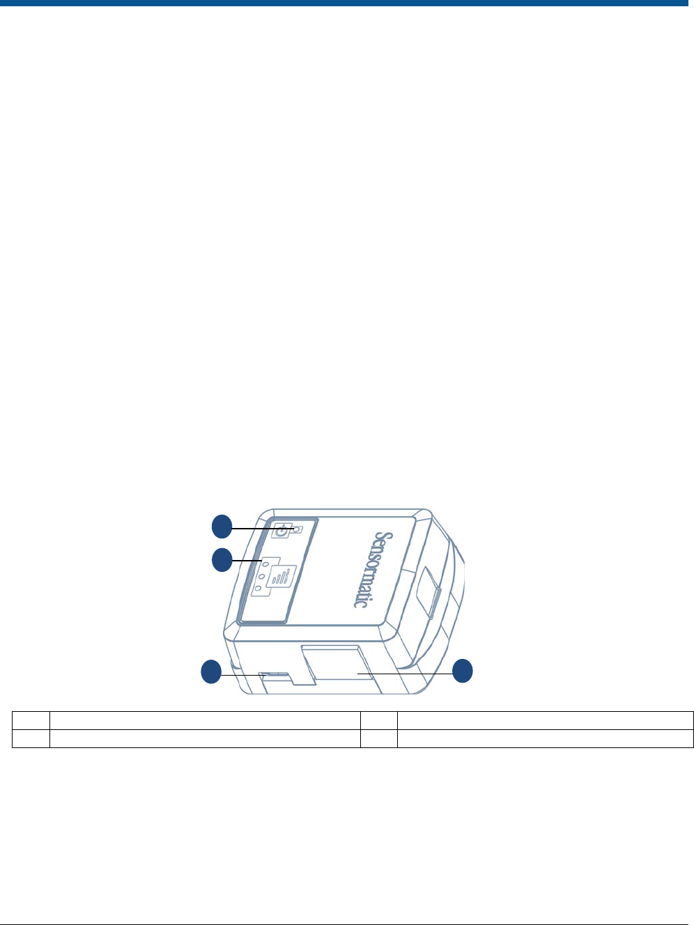
Figure 1. BIX1000
A
RS-485 port
B
Signal strength LED indicators
C
Status LED indicator
D
Micro USB port
A
B
C
D

PRELIMINARY
WIRELESS DEVICE MODULE (BIX1000) 8200-1088-15, REV 3D
INSTALLATION GUIDE 5 of 16 *8200-1088-15*
Compatibility
The Wireless Device Module (BIX1000) is compatible with the following devices:
• The Ultra Post® IV AMS-1012 Pedestal.
• The Ultra Post® VI AMS-1014 Pedestal.
• The Ultra 1.8 Meter ABS Pedestal.
• The AMS-9060 Controller.
• The AMS-9050 Controller.
• The AMS-9040 Controller.
• The AMS-1080 Controller.
• The AMS-1170-2C/4C Controller.
• The ZBAMB9010 EAS Label Deactivator Controller.
• The AMB9010-IPS EAS Label Deactivator Controller.
• The ZBSMPROE ScanMax® Pro Label Deactivator Controller.
• The AMB-1200C EAS Label Deactivator Controller.
• The AMK-1000 and the AMK-1010 SuperTag® Detacher.
• The IDKM-1000 and the IDKM-1010 SuperTag® Detacher.
• The AMB-2011 Value Pad II Countertop EAS Label Deactivator.
• The AMB-1101 VersaPass II Countertop EAS Label Deactivator.
Cable kit numbers
Table 1 lists the cable kit numbers for the EAS devices that are compatible to install with a Wireless Device
Module (BIX1000).
Table 1. BIX1000 cable kit numbers, cable part numbers, and installation guide numbers
Description
Cable kit number
Cable part number
Installation guide
Ultra Post® IV AMS-1012 Pedestal
0352-0710-01
0652-0890-01
8200-1088-05
The Ultra Post® VI AMS-1014 Pedestal
0352-0711-01
0652-0891-01
8200-1088-06
Ultra 1.8 Meter ABS Pedestal
0352-0757-01
0652-0893-01
8200-1088-07
AMB9010-IPS and AMB-1200 EAS Label Deactivator
Controller
0352-0696-01 0652-0889-01 8200-1088-08
AMS-9060 Controller and AMS-1170-2C/4C Controller
0352-0695-01
0652-0888-01
8200-1088-11
AMS-9050 Controller
0352-0694-01
0652-0887-01
8200-1088-09
AMS-9040 Controller
0352-0693-01
0652-0886-01
8200-1088-10
ZBSMPROE ScanMax® Pro Label Deactivator
Controller
0352-0760-01
0652-0845-01
8200-1088-12
IDKN-10XX/AMK-10XX SuperTag® Detacher
0352-0697-01
0652-0892-01
8200-1088-13
Wireless Device Module BIX1000 Extension Cable Kit
0352-0765-01
0652-0894-01
8200-1088-14
AMB-2011 Value Pad II Countertop EAS Label
Deactivator, AMB-1101 VersaPass II Countertop EAS
Label Deactivator, and ZBAMB9010 EAS Label
Deactivator Controller
0352-0780-01
0652-0898-01
8200-1088-16
AMS-1080 Controller
0352-0789-01
0652-0901-01
8200-1088-17

PRELIMINARY
WIRELESS DEVICE MODULE (BIX1000) 8200-1088-15, REV 3D
INSTALLATION GUIDE 6 of 16 *8200-1088-15*
Tool requirements
You require the following tools to install the Wireless Device Module (BIX1000):
• A #2 Phillips head screwdriver.
• A small slotted screwdriver.
• A drill with a 3/32 inch (2.38 millimeter) drill bit.
• A micro USB cable, 6003-0313-01, to connect to the BIX1000.
Section I: Before you begin
Before you install the Wireless Device Module (BIX1000), ensure that you adhere to the criteria in the following
sections.
System requirements
This section outlines the system requirements that you need to install a BIX1000.
Firmware requirements
To support the installation of the BIX1000, download the BIX Firmware Tool from
https://sensormaticsecurelogin.com/.
To download the BIX Firmware Tool, complete the following steps:
1. Open a web browser and launch https://sensormaticsecurelogin.com/.
2. Enter your valid log on information, and click Login.
3. From the Tech Support menu, click EAS.
4. Click Software Download.
5. Click BIX Firmware Tool.
6. To download the software bundle, click the link, and save the file to a local folder on your laptop.
7. Log out of www.sensormaticsecurelogin.com/.
8. On your laptop, rename the file that you saved to an .exe file. Click the executable file, and click Run.
9. Follow the setup wizard instructions to save the software on your laptop.
Note: Files save to the following location: C:\Program Files\Sensormatic\BIX Software Bundle
(Program Files (x86) for 64 bit machines).
Laptop requirements
Your laptop must have a USB port to connect to the Wireless Device Module (BIX1000).
Wiring requirements
For information on wiring requirements, see Table 1.

PRELIMINARY
WIRELESS DEVICE MODULE (BIX1000) 8200-1088-15, REV 3D
INSTALLATION GUIDE 7 of 16 *8200-1088-15*
Safety
You must adhere to the following safety instructions when you install a Wireless Device Module (BIX1000):
WARNING: Risk of electric shock
Disconnect all power sources before servicing.
• You must use plenum-rated cables, unless the cables are in raceways.
• Installation of the BIX1000 must comply with the latest national electrical codes, national fire code, and all
applicable local codes and ordinances. National or local wiring codes may differ between regions.
Adherence to these codes supersedes instructions in this document.
• You must observe and respect all the safety instructions in this installation guide, and the operation of the
BIX1000.
• You must mount the BIX1000 only as instructed in this installation guide. Mounting the BIX1000 any other
way can affect its operation.
• The manufacturer is not responsible for any radio or TV interference caused by unauthorized
modifications to this equipment. Such modifications can void the user’s authority to operate the
equipment.
• You must install the antennas for this transmitter with a separation distance of at least 20 centimetres
(8 inches) from all persons, and must not be co-located or operating in conjunction with any other
antenna or transmitter.
Installation prerequisites
To install the BIX1000, you must have the following criteria in place before you proceed:
• Have you completed the training required to commission the BIM1000 and BIX1000?
• Did you download the supporting firmware version for the BIX Firmware Tool?
• Did you download the supporting firmware version for the EAS devices that you are connecting to each
BIX1000?
• Is the BIM1000 installed?
• Is the BIM1000 turned on, and programmed with the Personal Area Network (PAN) ID and the Channel?
For information on configuring the radio settings, refer to the Commissioning the Wireless Device
Manager section in the Wireless Device Manager (BIM1000) and Wireless Device Module (BIX1000) Setup
Guide, 8200-1088-01.
PRELIMINARY
WIRELESS DEVICE MODULE (BIX1000) 8200-1088-15, REV 3d
INSTALLATION GUIDE 8 of 16 *8200-1088-15*
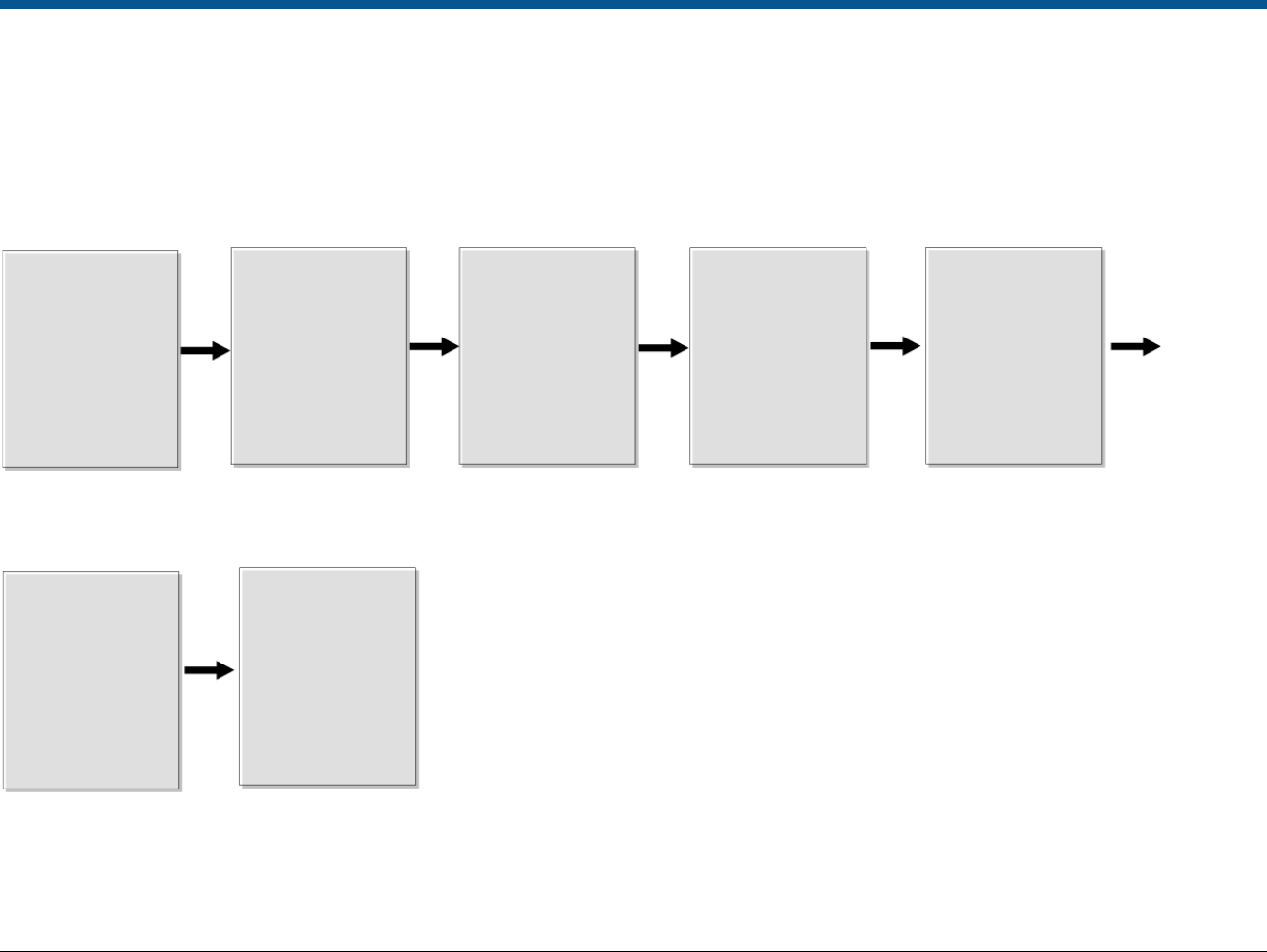
Section II: Installation sequence overview
Figure 2 gives an overview of the complete installation sequence you must follow when you install a BIM1000 and a BIX1000.
You must install the BIM1000 before you install the BIX1000.
Figure 2. BIM1000 and BIX1000 complete installation sequence
Important: This installation guide only describes the following steps in the complete BIM1000 and BIX1000 installation sequence:
• Before you begin: Planning and prerequisites
• Step 3: Commission the BIX1000
• Step 4: Install and locate the BIX1000
Before you begin:
Planning and
prerequisites
Step 2:
Install the BIX1000
cable kits
Step 4:
Install and locate
the BIX1000
Step 5:
Validate BIM1000
configuration
Step 6:
Validate BIM1000
remote connectivity
Install the
BIM1000. Turn
on the BIM1000,
and program the
PAN ID and the
Ch l
Install the
relevant
BIX1000 cable
kit, and
configure the
EAS d i
Install and
locate the
BIX1000
Validate the
complete
BIM1000 and
BIX1000
configuration
Validate the
remote
connectivity
and data
transportation
of the
Commission
the BIX1000
Step 3:
Commission the
BIX1000
Step 1:
Install the
BIM1000
Confirm all the
prerequisites in
Section I are
complete
before
beginning

PRELIMINARY
WIRELESS DEVICE MODULE (BIX1000) 8200-1088-15, REV 3a
INSTALLATION GUIDE 9 of 16 *8200-1088-15*
Section III: Installing the BIX1000
This section outlines how to install a Wireless Device Module (BIX1000).
Important: You must install the Wireless Device Manager (BIM1000) before you install the Wireless Device
Module (BIX1000) to verify that the signal strength is sufficient in the selected mounting location.
Overview of steps
This section gives an overview of the steps to install a BIX1000:
• Step 1: Connecting the BIX1000 cable to the EAS device
• Step 2: Commissioning the BIX1000
• Step 3: Locating the BIX1000
Step 1: Connecting the BIX1000 cable to the EAS device
You must connect the BIX1000 to compatible EAS devices using the appropriate cable kit. The RJ45 end of
each cable kit is labelled to indicate which end of the cable connects to the RS-485 port on the BIX1000. For
the location of the RS-485 port on the BIX1000, see item A in Figure 1.
To connect the BIX1000 to a compatible EAS device, complete the following step:
• Select the EAS device you are installing from Table 1, and connect the EAS device to the BIX1000, as
described in the relevant installation guide.
Note: When you connect the EAS device to the BIX1000, the Status LED on the BIX1000 should change to
solid green within 20 seconds. For information on the BIX1000 status LEDs, see Table 4.
Step 2: Commissioning the BIX1000
Before you secure the BIX1000, you must commission it in order to test different mounting locations and to
verify signal strength.
Note: For more information on how to commission the BIX1000, refer to the Wireless Device Manager
(BIM1000) and Wireless Device Module (BIX1000) Setup Guide, 8200-1088-01.
To commission the Wireless Device Module (BIX1000), complete the following steps:
1. If installing the BIX1000EA module, locate the SMA antenna, 3411-0024-01, from the BIX1000 installation
kit, and screw the SMA antenna into the SMA connection port on the BIX1000EA.
Figure 3. SMA antenna to SMA connector on the BIX1000EA
A
SMA antenna, 3411-0024-01
B
SMA connection port
C
BIX1000EA module
A
B
C

PRELIMINARY
WIRELESS DEVICE MODULE (BIX1000) 8200-1088-15, REV 3a
INSTALLATION GUIDE 10 of 16 *8200-1088-15*
2. Connect the micro USB cable, 6003-0313-01, to the BIX1000 micro USB port. For the location of the USB
port, see item D in Figure 1, on page 4. Connect the opposite end of the micro USB cable to the USB port
on your laptop.
Note: The laptop powers the BIX1000 through the USB port.
3. Wait 15 seconds for the BIX1000 boot sequence to complete.
4. When the BIX1000 boot sequence completes, launch the BIX Firmware Tool you downloaded pre-
installation.
5. Update the firmware on the BIX1000 by completing the following steps:
a. In the Controller Download pane, click Browse, and then select the supporting firmware version for the
BIX1000.
b. Click Start Flash Download.
Note: If an error occurs during the download, you must close the BIX Firmware Tool, disconnect the device,
and then repeat steps 2 to 6.
6. After the flash download, complete the following steps to establish communication between the BIM1000
and the BIX1000:
Important: In the following steps, ensure you save the changes to each individual parameter before you
change the next parameter.
a. Open the BIM Web Launch Tool, and from the BIM Configuration menu, click Radio Settings.
Record the values in the PAN ID and Channel fields, and then close the BIM Web Launch Tool.
b. Return to the BIX Firmware Tool window.
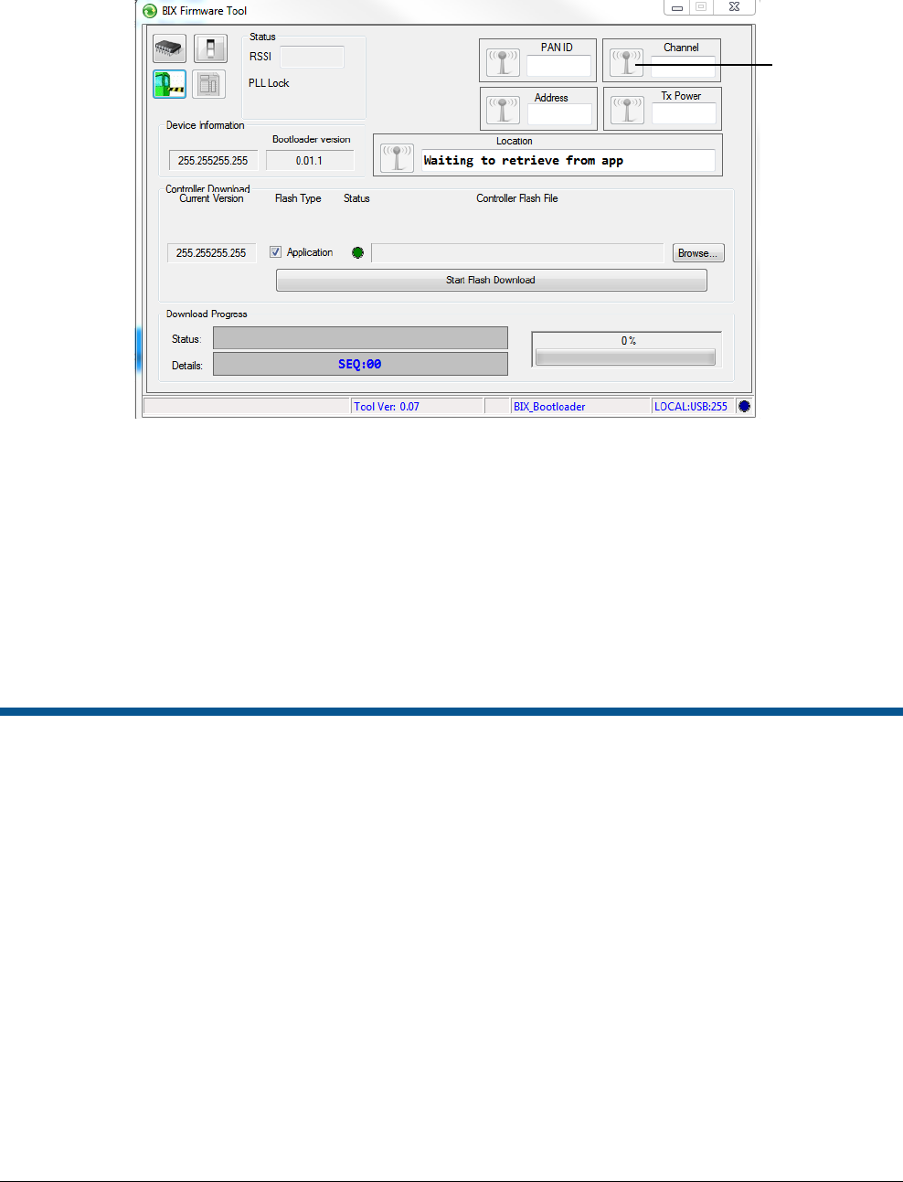
c. In the PAN ID field enter the PAN ID value you recorded for the BIM1000, and click the Antenna
icon to save the changes. For the location of the save button, see Figure 4.
Note: The PAN ID is limited to the hex characters A-F and 0-9. The PAN ID you set for the BIX1000
must match the PAN ID set for the BIM1000 to establish communication between the two devices.
d. In the Channel field, enter the Channel value you recorded from the BIM1000, and click the
Antenna icon to save the changes.
Note: You can set a value from 11 to 26 for IEEE 802.15.4 radio frequencies.
Regulatory restriction: Do not use channel 25 or channel 26 in North America.
e. In the Tx Power field, enter the Tx power value for the country of use, as shown in Table 2. Click
the Antenna icon to save the changes.
Table 2. BIM1000 and BIX1000 TX power
Device
TX power, North America
TX power, Europe
BIM1000
197 (20dB)
70 (10dB)
BIX1000
197 (20dB)
94 (10dB)
BIX1000EA
220 (20dB)
85 (10dB)
7. Optional: In the Location field, enter a description of the location of the BIX1000, for example, East
Entrance. Click the Antenna icon to save the changes.
Note: Entering a location description helps to locate devices after installation.
PRELIMINARY
WIRELESS DEVICE MODULE (BIX1000) 8200-1088-15, REV 3a
INSTALLATION GUIDE 11 of 16 *8200-1088-15*
Figure 4. BIX Firmware Tool window
8. With the BIX1000 connected to your laptop, temporarily place the BIX1000 in the area where you are
installing it to validate the signal strength. For information on the BIX1000 signal strength indicators, see
Step 3: Locating the BIX1000.
Note: When validating the signal strength, ensure you are within the coverage range of the BIM1000.
9. Close the BIX Firmware Tool.
Important: You must close the BIX Firmware Tool before you disconnect the micro USB cable from the
BIX1000. If you do not close the BIX Firmware Tool first, the drivers for the BIX1000 can lock and the app
may not connect to the BIX1000. If this occurs, you must restart your laptop to resolve the issue.
10. Disconnect the micro USB cable, 6003-0313-01, from the BIX1000.
Step 3: Locating the BIX1000
Adhere to the following guidelines when determining the installation location of the BIX1000:
• Do not directly hold the BIX1000 module because your body and hand can detune the antenna.
• The BIX1000 can be orientation sensitive at the periphery of its range to the BIM1000.
• The wireless communication between the BIM1000 and the BIX1000 solution is most effective when the
modules are within a direct line of sight. Avoid placing the BIX1000 modules in metal enclosures or deep
underneath counters. Placing the BIX1000 on a higher mounting location can extend its signal strength.
Important: If you connect the BIX1000 to an AMS-9060 controller, an AMS-9050 controller, or an AMS-9040
controller, do not secure the BIX1000 to the case of the controller.
To locate the BIX1000 correctly, complete the following steps:
1. After you connect the BIX1000 to the EAS device using the appropriate cable installation kit, determine the
location of the BIX1000.
Notes:
• You must place the BIX1000 a minimum of 2 feet (24 inches) from the BIM1000.
Antenna icons,
click to save
parameters

PRELIMINARY
WIRELESS DEVICE MODULE (BIX1000) 8200-1088-15, REV 3a
INSTALLATION GUIDE 12 of 16 *8200-1088-15*
• Table 3 lists the expected maximum line of sight range from the BIM1000 module to the BIX1000
module for each region. The maximum line of sight ranges are based on environments free of
obstructions and interference. The range can significantly degrade from the specified maximums.
Table 3. Expected maximum line of sight ranges from the BIM1000 to the BIX1000
Modules Region Expected maximum line of sight range
BIM1000 to BIX1000
EU
76.2 meters (250 feet)
BIM1000 to BIX1000EA
EU
106.7 meters (350 feet)
BIM1000 to BIX1000
US
106.7 meters (350 feet)
2. Optional: If you need to locate the BIX1000 further away from the EAS device for improved signal reception
or for mounting purposes, install the BIX1000 Extension Cable Kit, 0352-0765-01, as described in the
Wireless Device Module (BIX1000) Extension Cable Kit Installation Guide, 8200-1088-14.
Note: Use the BIX1000 Cable Extension Kit to relocate the BIX1000 module up to 3.3 meters (10 feet)
away from the EAS device to which you are connecting the BIX1000.
3. Ensure that the status LED on the BIX1000 is green. For information on the status LED descriptions, see
Table 4.
Table 4. BIX1000 status LED description
BIX1000 status LED color BIX1000 status description
No status LED displaying
Powered off or in Boot Loader Mode
Status LED displaying green
Operating correctly
Status LED flashing amber quickly
Attempting communication with an EAS device
Status LED flashing amber slowly
The Phase Lock Loop (PLL) is unlocked, and indicates a synchronization error
Status LED flashing red
There is no communication between the BIX1000 and the BIM1000
4. To ensure strong signal strength, select one of the following options:
• Ensure the signal strength LEDs on the BIX1000 display at least one green LED. If it does not, move
the BIX1000 until it displays one or more green LEDs. For information on the signal strength
indicators on the BIX1000, see Table 5.
• Connect the BIX1000 to your laptop and wait for the BIX1000 boot sequence to complete as
described in steps 2 to 5 on page 9, and then use the BIX Firmware Tool to determine the Received
Signal Strength Indicators (RSSI) value.
Table 5. BIX1000 signal strength LED description
BIX1000 signal strength LED color RX signal strength description
No green signal strength LEDs displaying
Signal strength is below -85 decibels
One green signal strength LED displaying
Signal strength is -85 to -75 decibels
Two green signal strength LEDs displaying
Signal strength is -75 to -60 decibels
Three green signal strength LEDS displaying
Signal strength is above -60 decibels
5. When you identify an ideal mounting location, locate the alcohol pads, 1600-0033, from the BIX1000
Installation Kit, 0352-0733-01, and use the alcohol pads to clean the surface area of the mounting location.
6. Remove the release liner from the adhesive pad on the BIX1000, and secure it to the correct location near
or on the EAS device. For more information on a specific EAS device, refer to the relevant installation guide
listed in Table 1.
7. Optional: If you need to secure the BIX1000 using the screws supplied in the installation kit, complete the
following steps:
a. Locate the BIX1000 back cover plate, 0404-1244-01, from the BIX1000 Installation Kit,
0352-0733-01.

PRELIMINARY
WIRELESS DEVICE MODULE (BIX1000) 8200-1088-15, REV 3a
INSTALLATION GUIDE 13 of 16 *8200-1088-15*
b. Use the BIX1000 back cover plate as a template, and mark the location of the pilot holes on the
mounting surface.
c. Remove the BIX1000 back cover, and using a drill with a 3/32 inch or 2.38 millimeter drill bit, drill
two mounting holes in the mounting surface.
d. Insert the two screws, 5810-2042-120, from the installation kit into the BIX1000 back cover, and
into the two mounting holes in the mounting surface.
e. Ensure that the two mounting screws are recessed below the plastic surface, and secure the back
cover to the mounting surface.
Note: The screw holes on the BIX1000 back cover plate are symmetrical. The other features on the
BIX1000 back cover plate are not symmetrical because they accommodate the micro USB and the
RS-485 ports.
8. Secure the BIX1000 to its mounting surface.
PRELIMINARY
WIRELESS DEVICE MODULE (BIX1000) 8200-1088-15, REV 3a
INSTALLATION GUIDE 14 of 16 *8200-1088-15*
Specifications
Electrical
Power supply
Primary input .........................................................................................................................................................................
..................................................... / 5V – 24VDC input, Sync and RS485 through RJ45 8 pin header with LEDs for RS485.
Environmental
Operating temperature ..................................................... ........................................................ 0°C to 50°C (32°F to 122°F)
Relative humidity ............................................................. ............................................................ 0 to 90% non-condensing
Enclosure Rating ............................................................. ..................................................................................... UL94 V-O
Evaluated for altitudes less than 2,000 meters (6,561.68 feet)
Mechanical
Material: ........................................................................... .............................................................................................. ABS
Color: .............................................................................. ..................................................................................... Light grey
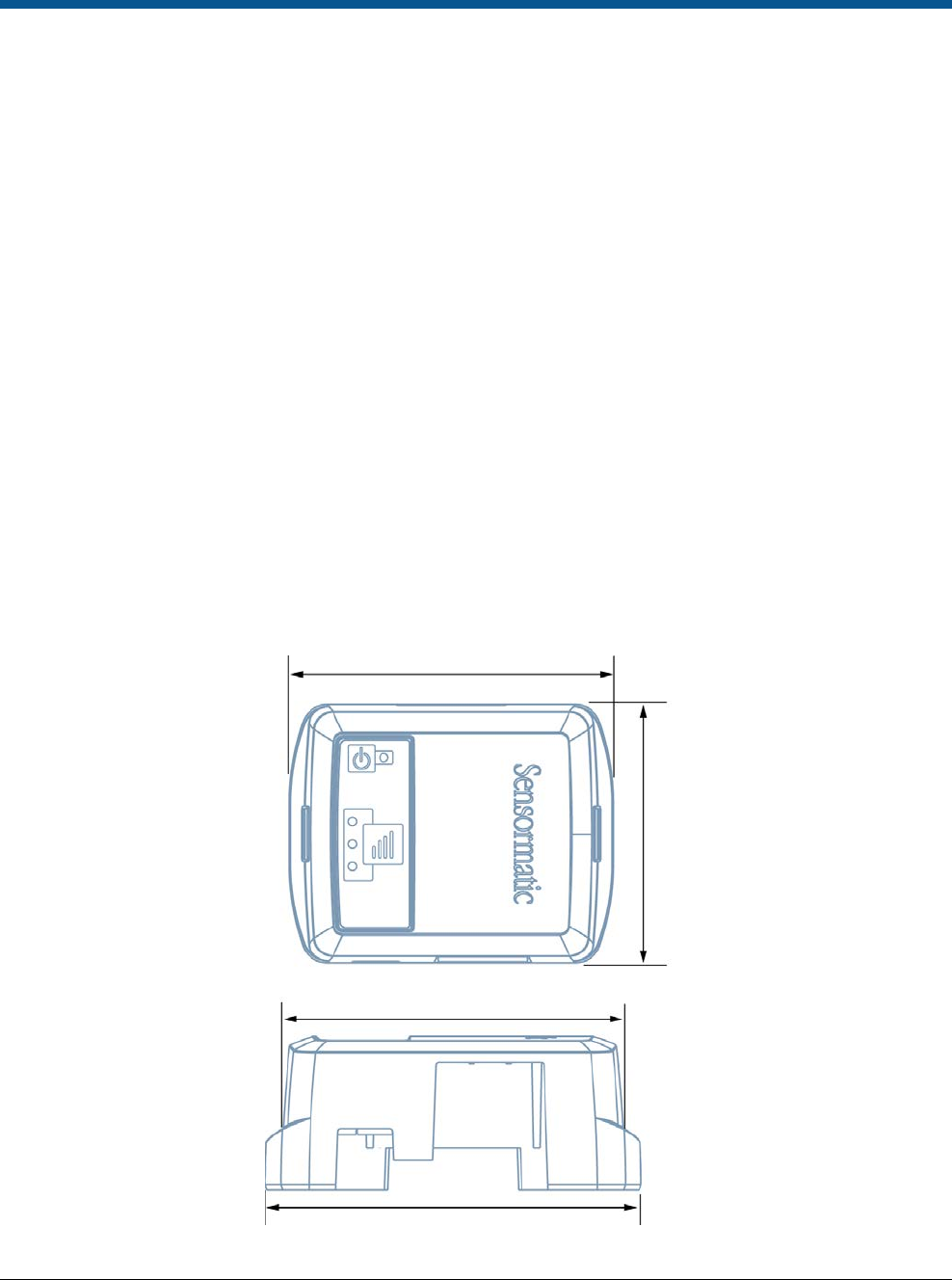
Dimensions: .................................................................... .................................................. 58.6 mm X 46.7 mm X 24.9 mm
Weight (approx.): ............................................................ ....................................................................... 32.66 g (0.072 lbs)
Dimensions
Figure 5. BIX1000 dimensions
58.5 mm
47 mm
58.5 mm
52.6 mm

PRELIMINARY
WIRELESS DEVICE MODULE (BIX1000) 8200-1088-15, REV 3a
INSTALLATION GUIDE 15 of 16 *8200-1088-15*
Declarations
Model: BIX1000
Regulatory information
Radio
Frequency of operation
Type.......................................................... .............................................................................................................. BIX1000
Frequency band............................. .......................................................................................................... .2400-2483.5 MHz
Maximum power ................................... ..................................................................................................... 10 mW in the EU
........................................................................................................................................................................ 100 mW in NA
If frequency is selectable for your model, select only the country
in which you are using the device. Any other selection will make
the operation of
this device illegal.
Approved antennas
Under Industry Canada regulations, this radio transmitter may
only operate using an antenna of a type and maximum (or
lesser) gain approved for the
transmitter by Industry Canada.
To reduce potential radio interference to other users, the
antenna type and its gain should be so chosen that the
equivalent isotropically radiated power
(e.i.r.p.) is not more than
that necessary for successful communication.
Conformément à la réglementation d’Industrie Canada, le
présent émetteur radio peut fonctionner avec une antenne d’un
type et d’un gain maximal
(ou inférieur) approuvé pour
l’émetteur par Industrie Canada.
Dans le but de réduire les risques de brouillage radioélectrique à l’intention des autres utilisateurs, il faut choisir le type d’antenne et son gain de sorte
que la puissance isotrope rayonnée équivalente (p.i.r.e.) ne dépasse pas l’intensité nécessaire à l’établissement d’une communication satisfaisante.
This radio transmitter IC: 3506A-BIX1000 has been approved
by Industry Canada to operate with the antenna types listed
below with the maximum
permissible gain and required antenna
impedance for each antenna type indicated. Antenna types not
included in this list, having a gain greater than the
maximum
gain indicated for that type, are strictly prohibited for use with
this device.
Le présent émetteur radio IC: 3506A-BIX1000 a été approuvé
par Industrie Canada pour fonctionner avec les types d’antenne
énumérés ci-dessous et
ayant un gain admissible maximal et
l’impédance requise pour chaque type d’antenne. Les types
d’antenne non inclus dans cette liste, ou dont le gain
est
supérieur au gain maximal indiqué, sont strictement interdits
pour l’exploitation de l’émetteur.
Pulse/Larsen W1027
Polarization ..................................................... .......................................................................................................... Vertical
Composite gain ............................................... .......................................................................................................... 3.2 dBi
Impedance .................................................... ......................................................................................................... 50 ohms
Pulse/Larsen W1038
Polarization ..................................................... .......................................................................................................... Vertical
Composite gain ............................................... .......................................................................................................... 3.8 dBi
Impedance .................................................... ......................................................................................................... 50 ohms
L-Com model HG2403RD-RSF
Polarization ..................................................... .......................................................................................................... Vertical
Composite gain ............................................... ........................................................................................................... 3.0 dBi
Impedance .................................................... ......................................................................................................... 50 ohms
Antenova model SRCW004
Polarization ..................................................... ............................................................................................................ Linear
Composite gain ............................................... .......................................................................................................... 2.5 dBi
Impedance .................................................... ......................................................................................................... 50 ohms
FCC ID: BVCBIX1000

PRELIMINARY
WIRELESS DEVICE MODULE (BIX1000) 8200-1088-15, REV 3a
INSTALLATION GUIDE 16 of 16 *8200-1088-15*
This device complies with part 15 of the FCC Rules. This device
complies with Industry Canada’s licence-exempt RSSs.
Operation is subject to the following two conditions: (1) This
device may not cause harmful interference, and (2) this device
must accept any
interference received, including interference
that may cause undesired operation.
México NOM 121: BIX1000
La operación de este equipo está sujeta a las siguientes dos
condiciones:
1)
es posible que este equipo o dispositivo no cause
interferencia perjudicial y
2)
este equipo debe aceptar cualquier interferencia, incluyendo
la que pueda causar su propia operación no deseada.
INTERNATIONAL ID: BIX1000
EMC ....................................................... .................................................................................................... 47 CFR, Part 15
............................................................................................................................................................................ EN 300 328
......................................................................................................................................................................... EN 301 489-1
......................................................................................................................................................................... EN 301 489-3
....................................................................................................................................................................... EN 301 489-17
................................................................................................................................................................................ RSS 210
Safety.......................................................... ................................................................................................. UL/EN 60950-1
............................................................................................................................................................... CSA C22.2.60950-1
EQUIPMENT MODIFICATION CAUTION: Equipment changes
or modifications not expressly approved by Sensormatic
Electronics, LLC, the party
responsible for FCC compliance,
could void the user’s authority to operate the equipment and
could create a hazardous condition.
See About this guide on page 3.
Other declarations
WARRANTY DISCLAIMER: Sensormatic Electronics, LLC
makes no representation or warranty with respect to the
contents hereof and specifically
disclaims any implied
warranties of merchantability or fitness for any particular
purpose. Further, Sensormatic Electronics, LLC reserves the
right
to revise this publication and make changes from time to
time in the content hereof without obligation of Sensormatic
Electronics, LLC to notify
any person of such revision or
changes.
LIMITED RIGHTS NOTICE: For units of the Department of
Defense, all documentation and manuals were developed at
private expense and no part
of it was developed using
Government Funds. The restrictions governing the use and
disclosure of technical data marked with this legend are set
forth in the definition of “limited rights” in paragraph (a) (15) of
the clause of DFARS 252.227.7013. Unpublished - rights
reserved under the
Copyright Laws of the United States.
TRADEMARK NOTICE: Sensormatic is a registered trademark
of Sensormatic Electronics, LLC. Other product names
mentioned herein may be
trademarks or registered trademarks
of Sensormatic or other companies.
No part of this guide may be reproduced in any form without
written permission from Sensormatic Electronics, LLC.