Tyco Safety Sensormatic CCW Access Control Reader User Manual 280301a frcov
Tyco Safety Products/Sensormatic Access Control Reader 280301a frcov
UserManual.wiki
>
Tyco Safety Sensormatic
>
CCW User Manual
users manual
Navigation menu
Upload a User Manual
Namespaces
Wiki Guide
HTML
PDF
Info
Views
User Manual
Discussion / Help
Navigation
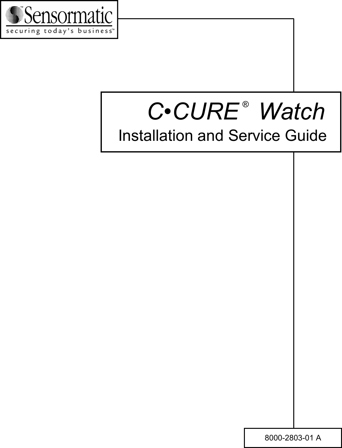

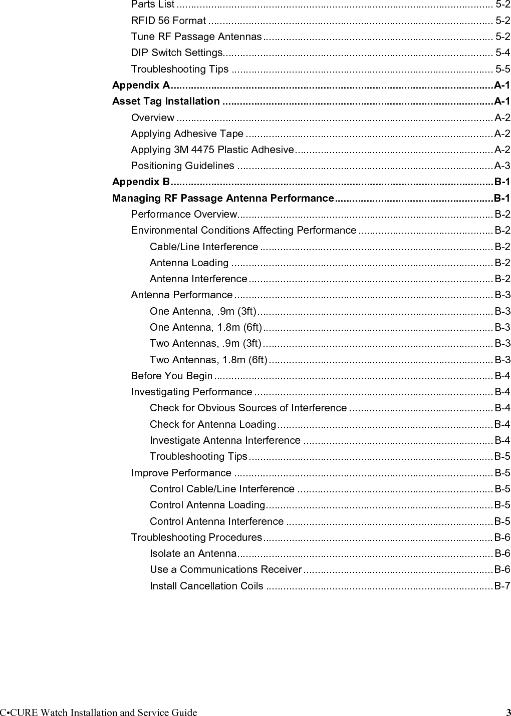

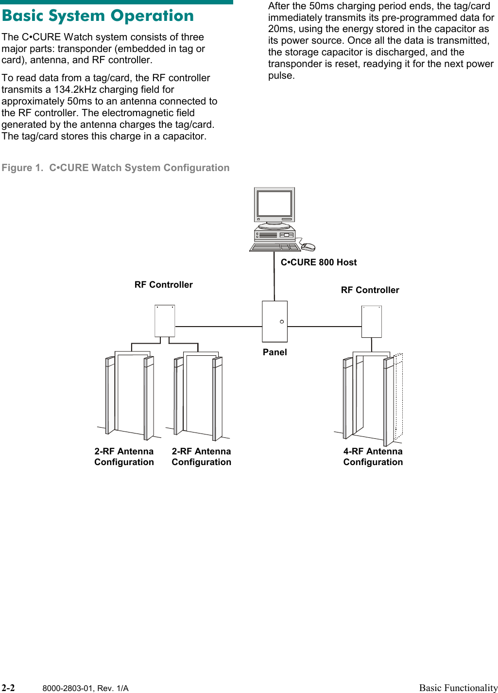
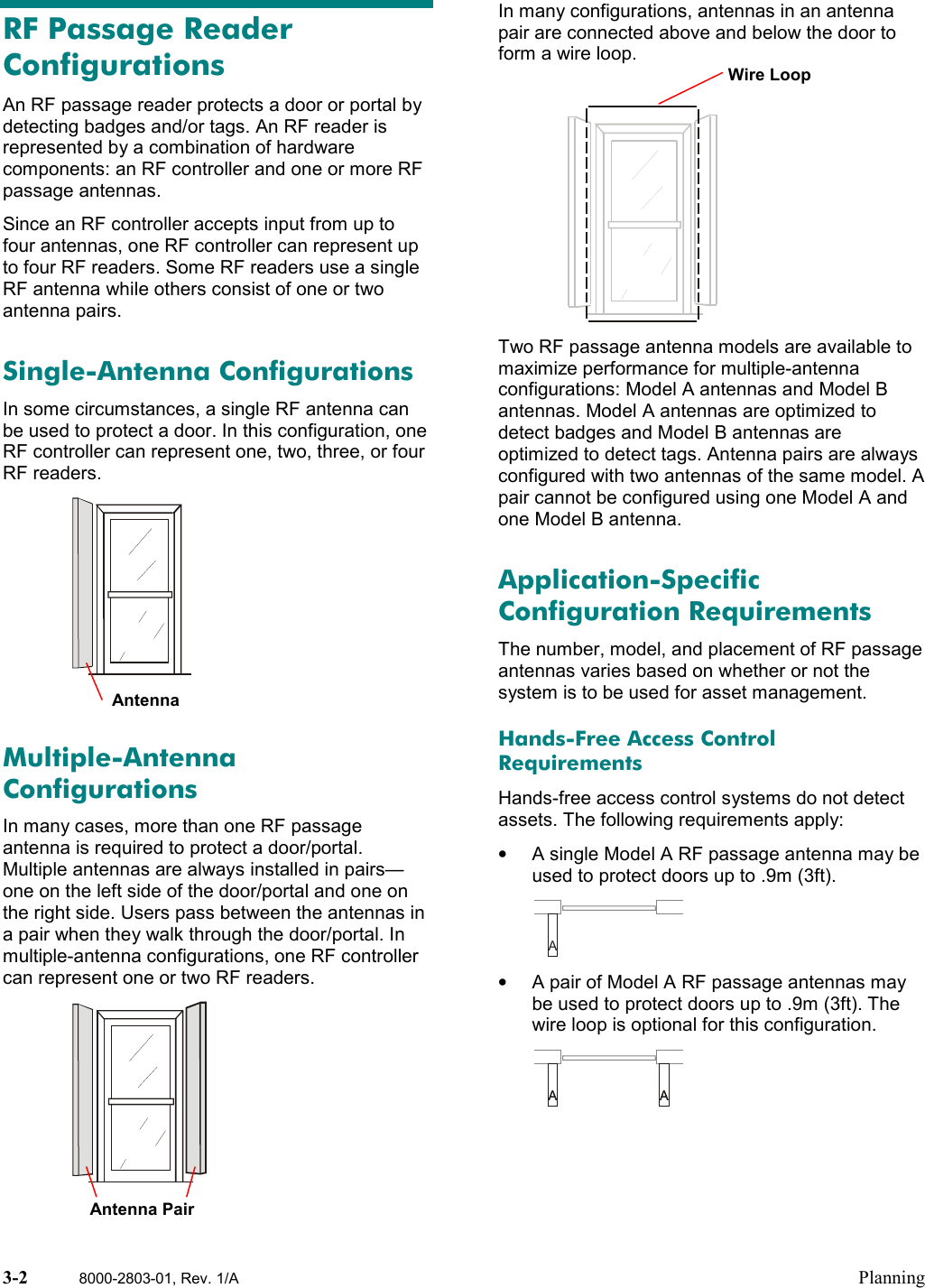
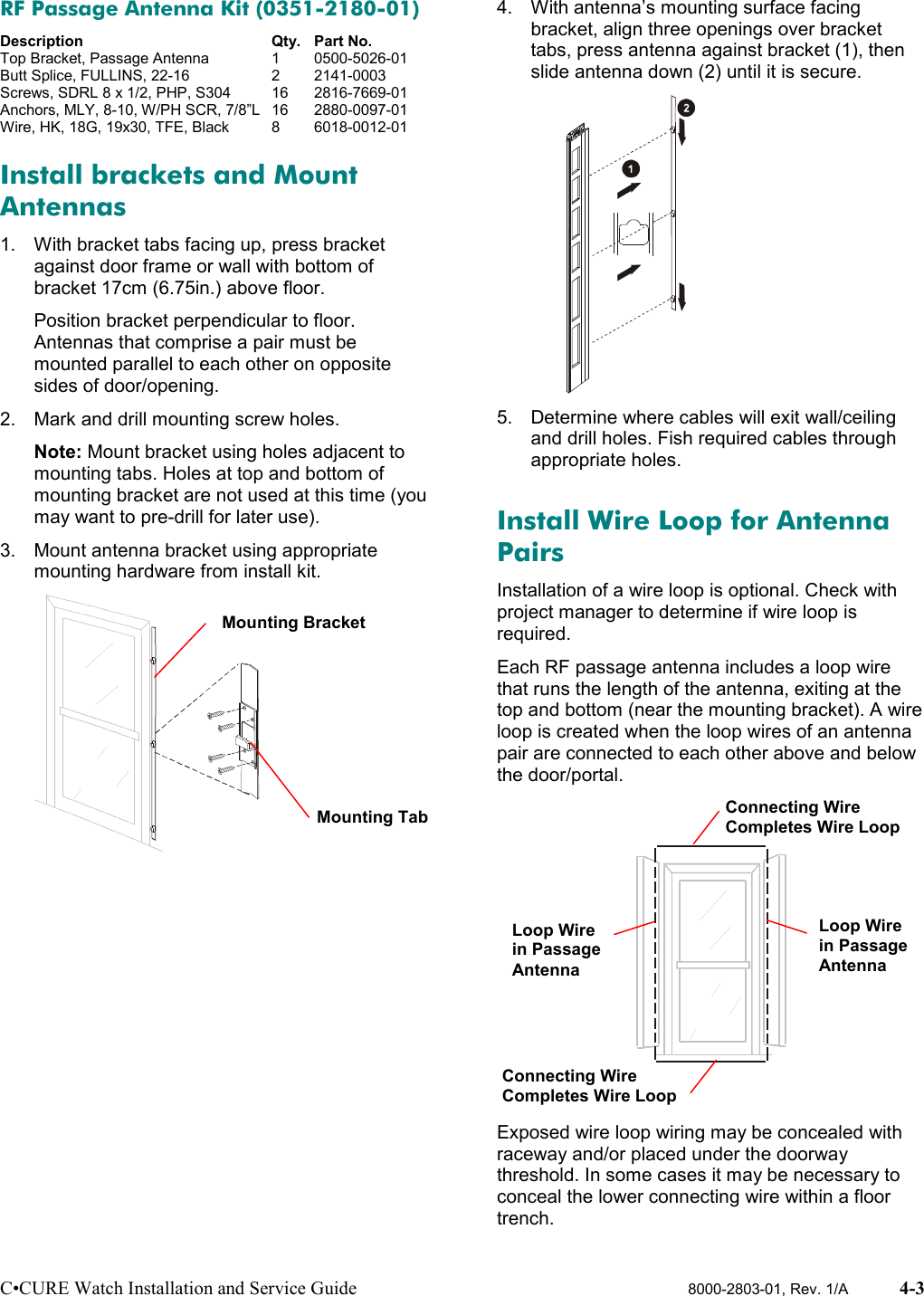
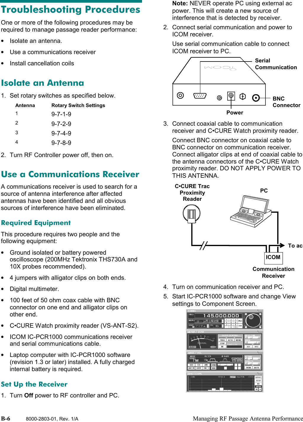
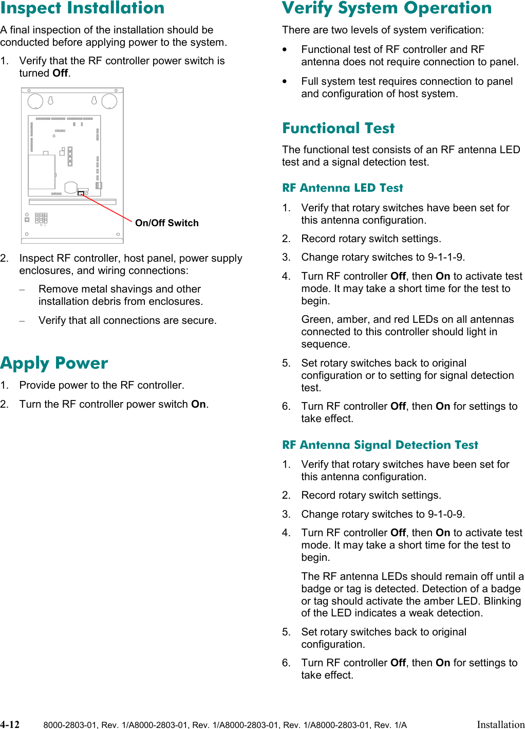
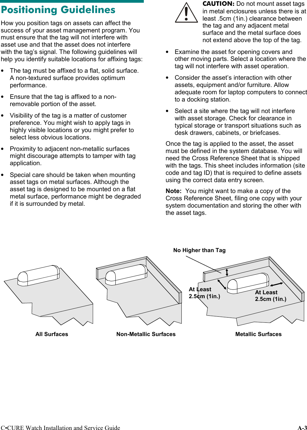
![4-4 8000-2803-01, Rev. 1/A8000-2803-01, Rev. 1/A8000-2803-01, Rev. 1/A8000-2803-01, Rev. 1/A Installation1. Remove door threshold, and determine if thereis adequate clearance to place connecting wireunder it without cutting a floor trench.2. If necessary, cut floor trench (0.3cm [1/8in.]wide by 1.2cm [1/2in.] deep).3. Locate ends of loop wire tucked into frame attop and bottom of each antenna.Note: Remove bottom cap to retrieve wireloop, feed through opening in cap, and re-install cap.4. Cut two pieces of wire to complete wire loopabove and below door/portal (connectingwires).5. Run top connecting wire above door/portal andconnect to antenna wire at top of eachantenna.6. Run bottom connecting wire under doorway.Conceal by replacing threshold or sealingtrench being careful not to pinch wire.7. Connect to antenna loop wire at bottom ofeach antenna.The wire loop is installed and ready to operate.Connect RF Controller CablesWARNING: RISK OF ELECTRICSHOCK! Read manual beforeservicing.1. Connect 8-conductor control cable from RFcontroller to terminal block on the RF antennaboard as follows:Pin FunctionPin 1 RX–Pin 2 RX+Pin 3 Red LEDPin 4 Amber LEDPin 5 Green LEDPin 6 LED GroundPin 7 TXPin 8 N/C2. Connect terminal block to control connector P2(pin 1 is at outside edge of board).3. Connect 2-conductor power cable to terminalblock as follows:Pin FunctionPin 1 +16VdcPin 2 ReturnPin 3 UnusedPin 4 Unused4. Connect terminal block to power connector P1(pin 1 is at bottom). Note: See Chapter 5: Service for informationabout verifying and optimizing antennaperformance.1: RX–2: RX+3: Green LED4: Amber LED5: Red LED6: LED Ground7: TX8: N/C4: Unused3: Unused2: Return1: Vcc!Loop Wire](https://usermanual.wiki/Tyco-Safety-Sensormatic/CCW/User-Guide-154546-Page-28.png)
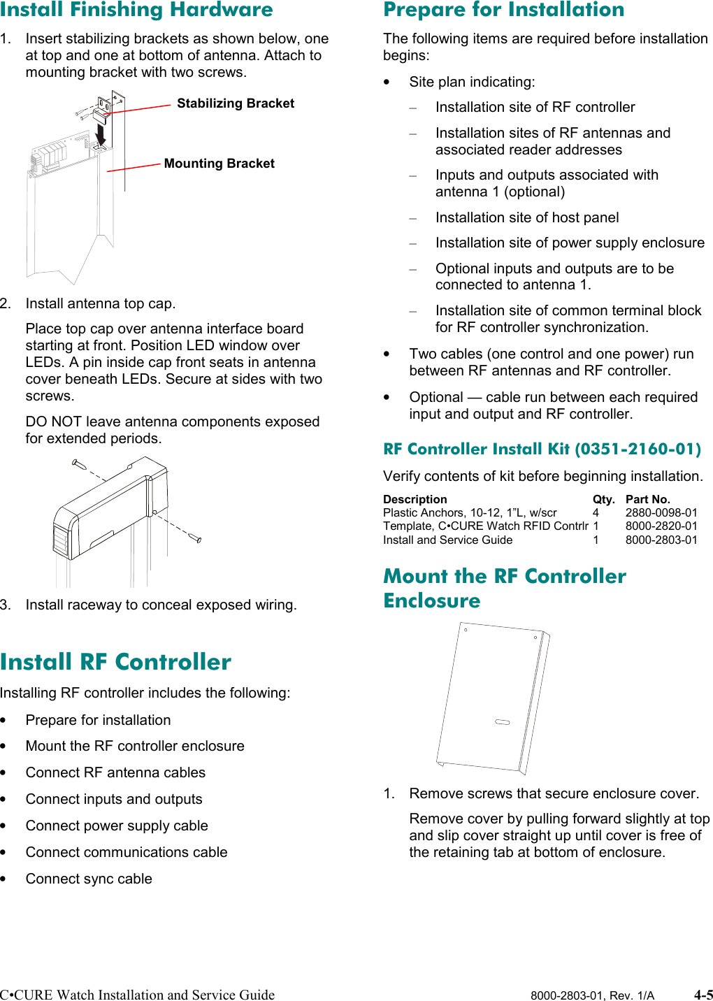
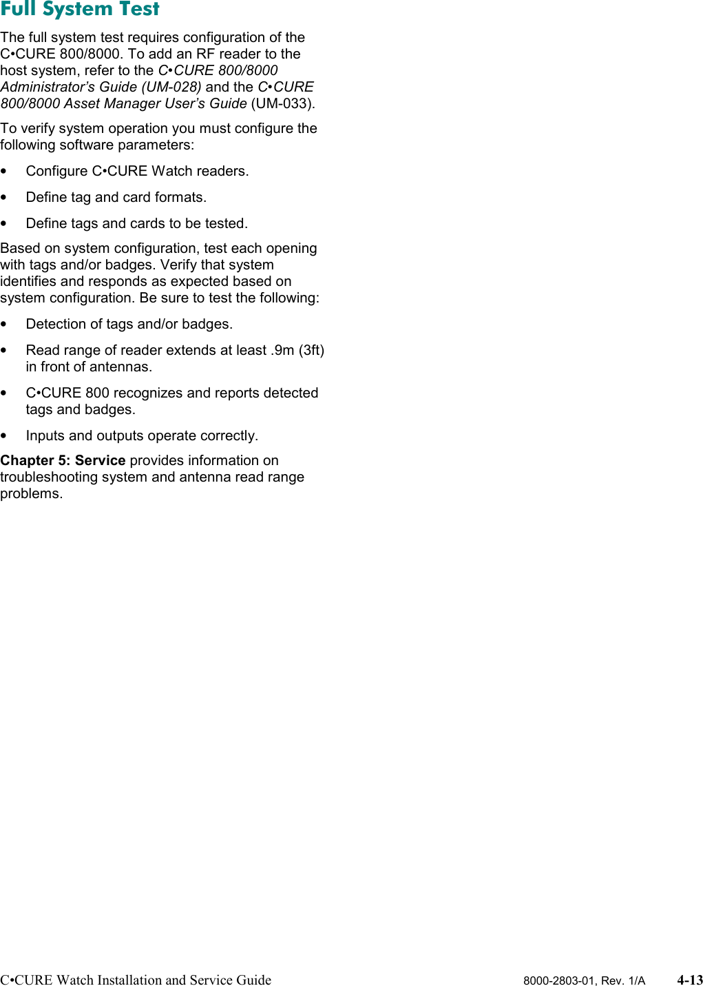

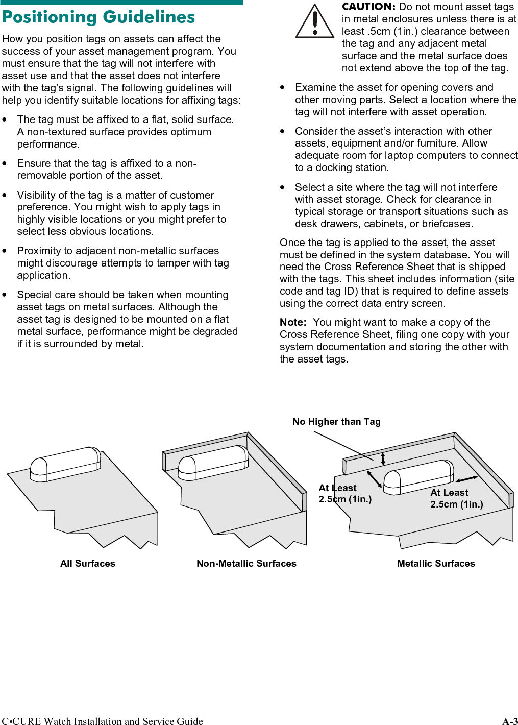
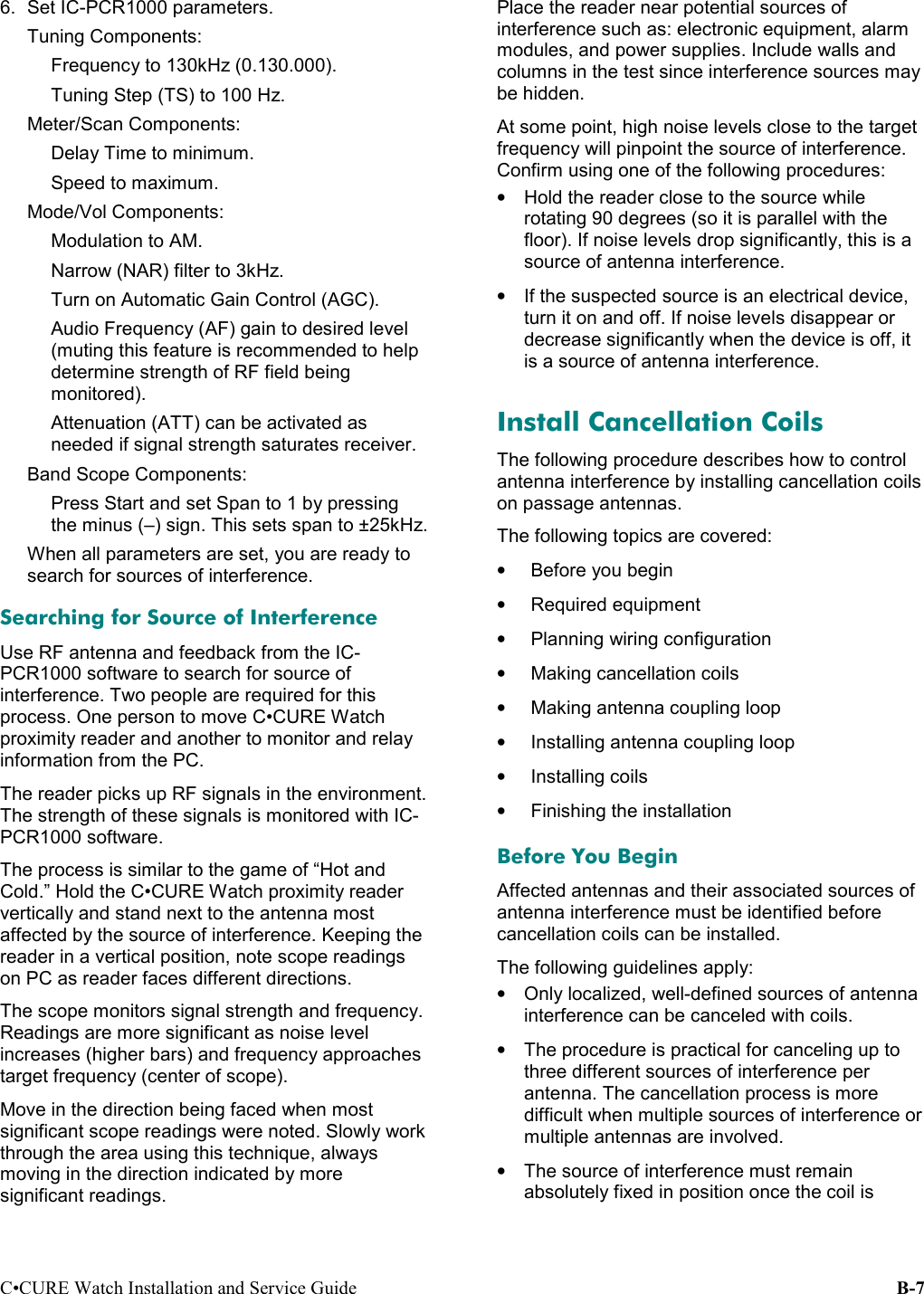
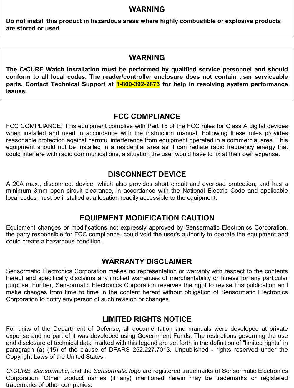
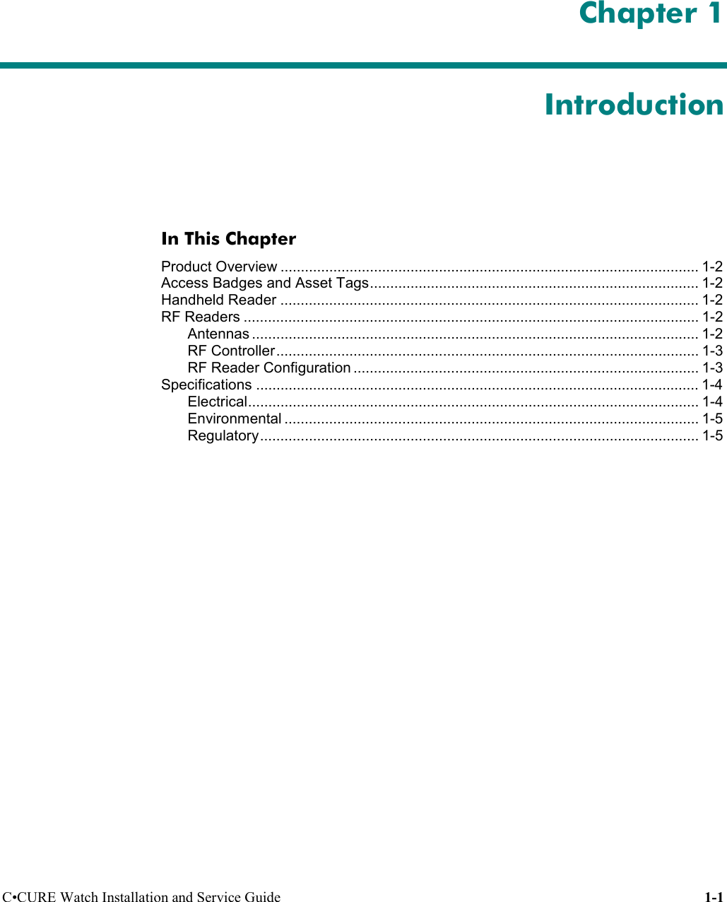
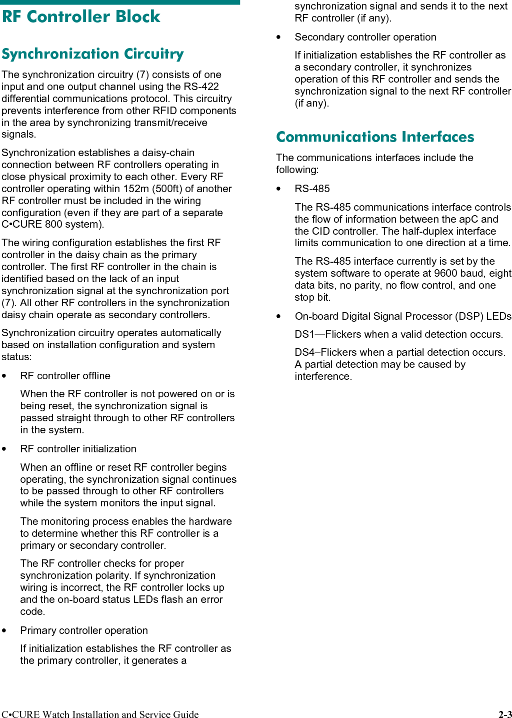
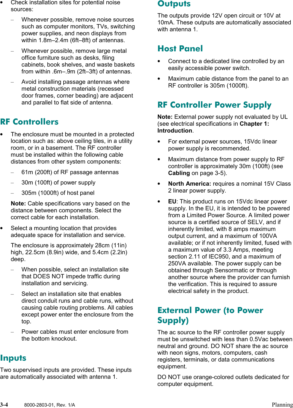
![C•CURE Watch Installation and Service Guide B-3Antenna PerformanceThe following antenna detection distances havebeen verified by UL.Note: “Top” means that detection occurred .6m(1.5ft) from the top of the antenna. “Bottom” meansdetection occurred .6m (1.5ft) from the floor.Detection occurred between the top and bottom inthe indicated distances.One Antenna, .9m (3ft)BadgeOrientationModel A (CW-ANT-PA) withWire LoopModel A (CW-ANT-PA) withoutWire LoopModel B (CW-ANT-PB) withoutWire LoopFrontal Top and bottom .9m (3ft) Top .9m (3ft)Bottom .76m (2.5ft)Top .9m (3ft)Bottom .76m (2.5ft)Vertical Top and bottom .76m (2.5ft) Top .6m (2ft)Bottom .76m (2.5ft)Top .76m (2.5ft)Bottom .6m (2ft)Lateral Top .76m (2.5ft)Bottom .6m (2ft)Top .9m (3ft)Bottom .76m (2.5ft)Top .76m (2.5ft)Bottom .9m (3ft)One Antenna, 1.8m (6ft)BadgeOrientationModel A (CW-ANT-PA) withWire LoopFrontal 1.8 m (6ft)Two Antennas, .9m (3ft)BadgeOrientationOne Model A (CW-ANT-PA) andOne Model B (CW-ANT-PB) with Wire LoopOne Model A (CW-ANT-PA) andOne Model B (CW-ANT-PB) without Wire LoopFrontal Top and bottom .9m (3ft) Top and bottom .9m (3ft)Vertical Top and bottom .76m (2.5ft) Top and bottom .9m (3ft)Lateral Top .76m (2.5ft)Bottom .6m (2ft)Top and bottom .76m (2.5ft)Two Antennas, 1.8m (6ft)BadgeOrientationTwo Model A (CW-ANT-PA) with Wire Loop Two Model A (CW-ANT-PA) without Wire LoopFrontal Top and bottom 1.8m (6ft) Top and bottom 1.8m (6ft)Vertical Top and bottom 1.5m (5ft)[.76m (2.5ft) from each side]Top and bottom 1.8m (6ft)Lateral Top 1.5m (5ft) [.76m (2.5ft) from each side]Bottom .9m (3ft) [.6m (1.5ft) from each side]Top 1.5m (5ft) [.76m (2.5ft) from each side]Bottom .9m (3ft) [.6m (1.5ft) from each side]FrontalLateralVertical](https://usermanual.wiki/Tyco-Safety-Sensormatic/CCW/User-Guide-154546-Page-53.png)