Tyco Safety Sensormatic CCW Access Control Reader User Manual 280301a frcov
Tyco Safety Products/Sensormatic Access Control Reader 280301a frcov
users manual
8000-2803-01 A
C•CURE ® Watch
Installation and Service Guide

Access Systems
C•CURE Watch
Installation and Service Guide
COPYRIGHT 2001
All rights reserved.
No part of this manual may be reproduced in any form without written permission
from Sensormatic Electronics Corporation.
8000-2803-01, Rev. 0/A
SHF 5/01
WARNING
Do not install this product in hazardous areas where highly combustible or explosive products
are stored or used.
WARNING
The C•CURE Watch installation must be performed by qualified service personnel and should
conform to all local codes. The reader/controller enclosure does not contain user serviceable
parts. Contact Technical Support at 1-800-392-2873 for help in resolving system performance
issues.
FCC COMPLIANCE
FCC COMPLIANCE: This equipment complies with Part 15 of the FCC rules for Class A digital devices
when installed and used in accordance with the instruction manual. Following these rules provides
reasonable protection against harmful interference from equipment operated in a commercial area. This
equipment should not be installed in a residential area as it can radiate radio frequency energy that
could interfere with radio communications, a situation the user would have to fix at their own expense.
DISCONNECT DEVICE
A 20A max., disconnect device, which also provides short circuit and overload protection, and has a
minimum 3mm open circuit clearance, in accordance with the National Electric Code and applicable
local codes must be installed at a location readily accessible to the equipment.
EQUIPMENT MODIFICATION CAUTION
Equipment changes or modifications not expressly approved by Sensormatic Electronics Corporation,
the party responsible for FCC compliance, could void the user's authority to operate the equipment and
could create a hazardous condition.
WARRANTY DISCLAIMER
Sensormatic Electronics Corporation makes no representation or warranty with respect to the contents
hereof and specifically disclaims any implied warranties of merchantability or fitness for any particular
purpose. Further, Sensormatic Electronics Corporation reserves the right to revise this publication and
make changes from time to time in the content hereof without obligation of Sensormatic Electronics
Corporation to notify any person of such revision or changes.
LIMITED RIGHTS NOTICE
For units of the Department of Defense, all documentation and manuals were developed at private
expense and no part of it was developed using Government Funds. The restrictions governing the use
and disclosure of technical data marked with this legend are set forth in the definition of “limited rights” in
paragraph (a) (15) of the clause of DFARS 252.227.7013. Unpublished - rights reserved under the
Copyright Laws of the United States.
C•CURE, Sensormatic, and the Sensormatic logo are registered trademarks of Sensormatic Electronics
Corporation. Other product names (if any) mentioned herein may be trademarks or registered
trademarks of other companies.

C•CURE Watch Installation and Service Guide 1
Table of Contents
Error! Bookmark not defined.
Table of Contents ........................................................................................................ 1
Chapter 1 ................................................................................................................... 1-1
Introduction............................................................................................................... 1-1
Product Overview................................................................................................. 1-2
Access Badges and Asset Tags .......................................................................... 1-2
Handheld Reader ................................................................................................. 1-2
RF Readers.......................................................................................................... 1-2
Antennas........................................................................................................ 1-2
RF Controller ................................................................................................. 1-3
RF Reader Configuration............................................................................... 1-3
Specifications ....................................................................................................... 1-4
Electrical ........................................................................................................ 1-4
Environmental................................................................................................ 1-5
Regulatory ..................................................................................................... 1-5
Chapter 2 ................................................................................................................... 2-1
Basic Functionality................................................................................................... 2-1
Basic System Operation ...................................................................................... 2-2
RF Controller Block.............................................................................................. 2-3
Synchronization Circuitry............................................................................... 2-3
Communications Interfaces ........................................................................... 2-3
Chapter 3 ................................................................................................................... 3-1
Planning..................................................................................................................... 3-1
RF Passage Reader Configurations .................................................................... 3-2
Single-Antenna Configurations...................................................................... 3-2
Multiple-Antenna Configurations ................................................................... 3-2
Application-Specific Configuration Requirements ......................................... 3-2
28000-2803-01, Rev. 1/A Table of Contents
Coordinating with Software Features................................................................... 3-3
Configuration Requirements ................................................................................ 3-3
RF Passage Antennas................................................................................... 3-3
RF Controllers ............................................................................................... 3-4
Inputs ............................................................................................................. 3-4
Outputs .......................................................................................................... 3-4
Host Panel ..................................................................................................... 3-4
RF Controller Power Supply .......................................................................... 3-4
External Power (to Power Supply) ................................................................ 3-4
Cabling........................................................................................................... 3-5
Asset Tag ...................................................................................................... 3-6
Access Control Badge ................................................................................... 3-6
Tools and Equipment ........................................................................................... 3-6
Chapter 4 ................................................................................................................... 4-1
Installation................................................................................................................. 4-1
Installation Checklist ............................................................................................ 4-2
Phase 1: Hardware Installation ..................................................................... 4-2
Phase 2: System Activation and Test............................................................ 4-2
Install Cable Runs ................................................................................................ 4-2
Install RF Passage Antennas............................................................................... 4-2
Prepare for Installation .................................................................................. 4-2
Install brackets and Mount Antennas ............................................................ 4-3
Install Wire Loop for Antenna Pairs............................................................... 4-3
Connect RF Controller Cables ...................................................................... 4-4
Install Finishing Hardware ............................................................................. 4-5
Install RF Controller ............................................................................................. 4-5
Prepare for Installation .................................................................................. 4-5
Mount the RF Controller Enclosure ............................................................... 4-5
Connect RF Antenna Cables......................................................................... 4-6
Connect Inputs and Outputs.......................................................................... 4-8
Connect Communications Cable................................................................... 4-9
Connect Sync Cable...................................................................................... 4-9
Connect RF Reader at Panel............................................................................. 4-10
Connect Power to RF Controller ........................................................................ 4-10
Connect Model CW-RID-1 to AC Power ..................................................... 4-10
Inspect Installation ............................................................................................. 4-12
Apply Power ....................................................................................................... 4-12
Verify System Operation .................................................................................... 4-12
Functional Test ............................................................................................ 4-12
Full System Test.......................................................................................... 4-13
Chapter 5 ................................................................................................................... 5-1
Service ....................................................................................................................... 5-1
C•CURE Watch Installation and Service Guide 3
Parts List .............................................................................................................. 5-2
RFID 56 Format ................................................................................................... 5-2
Tune RF Passage Antennas................................................................................ 5-2
DIP Switch Settings.............................................................................................. 5-4
Troubleshooting Tips ........................................................................................... 5-5
Appendix A................................................................................................................A-1
Asset Tag Installation ..............................................................................................A-1
Overview ..............................................................................................................A-2
Applying Adhesive Tape ......................................................................................A-2
Applying 3M 4475 Plastic Adhesive.....................................................................A-2
Positioning Guidelines .........................................................................................A-3
Appendix B................................................................................................................B-1
Managing RF Passage Antenna Performance.......................................................B-1
Performance Overview.........................................................................................B-2
Environmental Conditions Affecting Performance ...............................................B-2
Cable/Line Interference .................................................................................B-2
Antenna Loading ...........................................................................................B-2
Antenna Interference .....................................................................................B-2
Antenna Performance ..........................................................................................B-3
One Antenna, .9m (3ft) ..................................................................................B-3
One Antenna, 1.8m (6ft) ................................................................................B-3
Two Antennas, .9m (3ft) ................................................................................B-3
Two Antennas, 1.8m (6ft) ..............................................................................B-3
Before You Begin .................................................................................................B-4
Investigating Performance ................................................................................... B-4
Check for Obvious Sources of Interference ..................................................B-4
Check for Antenna Loading ...........................................................................B-4
Investigate Antenna Interference ..................................................................B-4
Troubleshooting Tips .....................................................................................B-5
Improve Performance ..........................................................................................B-5
Control Cable/Line Interference ....................................................................B-5
Control Antenna Loading...............................................................................B-5
Control Antenna Interference ........................................................................B-5
Troubleshooting Procedures................................................................................B-6
Isolate an Antenna.........................................................................................B-6
Use a Communications Receiver ..................................................................B-6
Install Cancellation Coils ...............................................................................B-7
48000-2803-01, Rev. 1/A Table of Contents

C•CURE Watch Installation and Service Guide 1-1
Chapter 1
Introduction
In This Chapter
Product Overview ....................................................................................................... 1-2
Access Badges and Asset Tags................................................................................. 1-2
Handheld Reader ....................................................................................................... 1-2
RF Readers ................................................................................................................ 1-2
Antennas .............................................................................................................. 1-2
RF Controller........................................................................................................ 1-3
RF Reader Configuration ..................................................................................... 1-3
Specifications ............................................................................................................. 1-4
Electrical............................................................................................................... 1-4
Environmental ...................................................................................................... 1-5
Regulatory............................................................................................................ 1-5
1-2 8000-2803-01, Rev. 1/A Introduction
Product Overview
C•CURE Watch products use RFID (radio
frequency identification) technology to gather
unique identification data from access control
badges and asset tags. This information is sent to
the C•CURE 800/8000 Access Control System
(host) for customized event handling and database
storage.
The components of a C•CURE Watch solution
include:
• Access badges and asset tags
• Handheld reader
• RF Readers
Access Badges and Asset
Tags
C•CURE Watch badges and tags are small,
passive devices that contain a transponder
encoded with unique data. This data is detected
and decoded by RF readers and sent to the host
for processing.
Access badges identify individuals. When a
C•CURE Watch RF reader detects an access
badge, identification data is sent to the host system
which decides whether to open the door or initiate
other actions based on the privileges assigned to
that individual.
Asset tags are permanently affixed to assets that
the user wants to manage. When a C•CURE
Watch RF reader detects an asset tag,
identification data is sent to the host system which
responds based on the privileges assigned to that
asset.
Handheld Reader
A handheld reader is available for initializing
assets. Asset tags must be initialized before they
can be assigned to specific assets in the host
system.
RF Readers
A C•CURE Watch RF reader is different from a
typical access control reader. It is a “virtual”
component that is comprised of two different
C•CURE Watch components: one or more
antennas and an RF controller. RF antennas can
be connected to an RF controller in a variety of
configurations that represent from one to four RF
readers.
An RF reader protects a door or portal up to six
feet wide by establishing an interrogation zone.
When an access badge or asset tag enters this
zone, its identification data is captured and sent to
the host for processing.
Each RF reader is recognized as a separate door
or portal by the host system.
Antennas
C•CURE Watch products include two types of
antenna which can be configured as part of an RF
reader: RF passage antenna and RF proximity
antenna (not yet available).
Under the direction of an RF controller, RF
antennas transmit and receive radio signals that
enable them to gather data from badges and tags.
This data is sent to the RF controller for decoding
and transmission to the host.
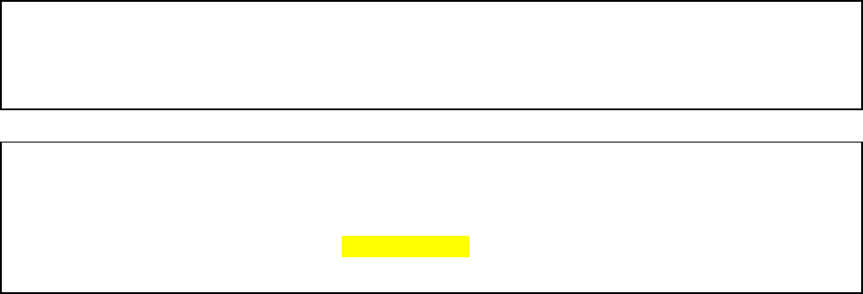
RF Passage Antenna
The RF passage antenna is designed to detect
both access badges and asset tags by establishing
C•CURE Watch Installation and Service Guide 1-3
an extended interrogation zone that makes badge
and tag detection practically transparent to users. It
does not require line of sight and operates without
any special presentation effort.
RF passage antennas can be installed at doors or
portals to monitor badges and/or assets. A portal is
any location where access is not restricted such
as: halls, passageways, and doors that are not
controlled by the host.
RF passage antennas are available in two models:
A and B. Model A RF passage antennas are
designed for hands-free access control
applications. Model B RF passage antennas work
in conjunction with model A RF passage antennas
for applications that monitor assets.
There are many ways to configure an RF reader
using RF passage antennas. The number and type
of antennas and their placement at the door or
portal depends on the size of the opening and the
security goals of the customer. For more
information about configuring RF readers with RF
passage antennas, see RF Reader Configuration
on page 1-3.
RF Proximity Antenna
The RF proximity antenna is not yet available.
The RF proximity antenna is designed to detect
only access badges. It establishes a limited
interrogation zone.
RF Controller
Every RF reader configuration includes an RF
controller. The RF controller directs the RF
antenna’s transmission and reception of radio
signals, conditions and decodes signals from the
antennas, and communicates with the host.
Each RF controller provides connections for up to
four antennas. These connections can represent
from one to four RF readers depending on antenna
type and board settings.
RF Reader Configuration
The RF controller provides a flexible foundation for
configuring RF readers. Each RF reader must
include at least one antenna connected to an RF
controller. However, the RF controller provides
connections for up to four antennas enabling a
single RF controller to represent multiple RF
readers to the host.
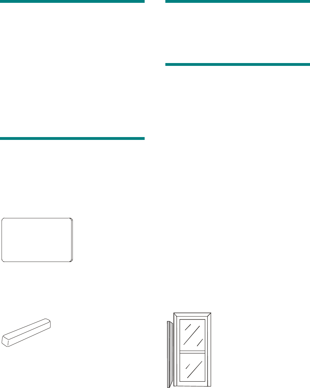
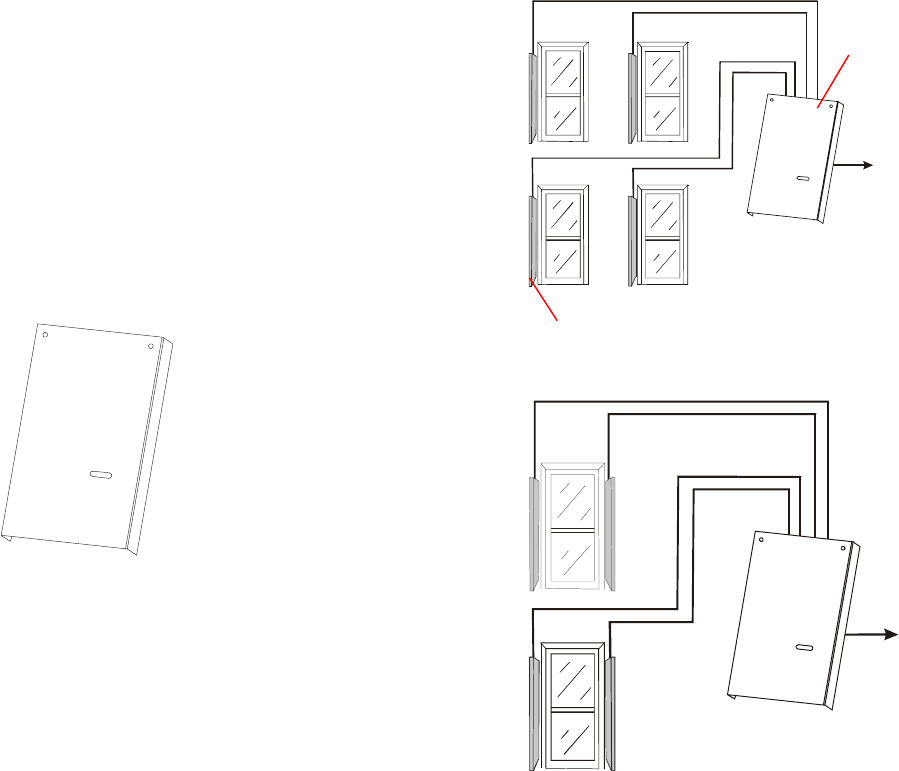
RF Passage Antenna Configurations
RF passage antennas can be configured in a
variety of ways depending on application
requirements and the size of the door/portal.
When four RF antennas are connected to an RF
controller, they may represent one, two, three, or
four RF readers depending on the address settings
selected.
RF Passage
Antenna
RF Controller
Recognized b
y
Host as Two
RF Readers
Recognized b
y
Host as Four
RF Readers
1-4 8000-2803-01, Rev. 1/A Introduction
The number of RF passage antennas required for
a particular door/portal depend on the size of the
opening being protected and whether the RF
reader is to recognize assets. The following
configurations are recommended:
Door/Portal
Width
Tags Only Badges
Only
Optimum
Performance
Up to
.9m (3ft)
1 Model A
and 1
Model B
1 Model A 2 Model A and
2 Model B
.9m (3ft) –
1.8m (6ft)
2 Model A
and 2
Model B
2 Model A 2 Model A and
2 Model B
RF Proximity Antenna Configurations
RF proximity antennas are not available at this
time.
Specifications
Electrical
Transponder
Type: ..................................Passive, TIRIS® ,
read/write
...........................................(64-bit usable data
max.)
Style: ..................................Asset tag or access
control badge
Antennas
Input Requirements: ...........16V nominal @ 4A
peak
Type: ..................................Tunable passage
antenna
RF Controller
Input Requirements: ...........15V nominal @ 8A
peak
Power Fuse: .......................5A, 250V manufactured
by Semko or equivalent
Outputs:..............................10V @ 10 mA,
12V open circuit
Transmitter/Receiver
Operating Frequency: ........134.2kHz
Transmit/Receive Cycle: ....70ms
Transmit Time: ...................50ms
Receive Time: ....................20ms
Receiver Data Format: .......52-bit
Recognized b
y
Host as One
RF Reader

C•CURE Watch Installation and Service Guide 1-5
External Power Supply for RF Controller
North America:......Requires a nominal 15Vdc @
8A peak Class 2 linear power
supply. (Not investigated by
UL).
EU: This product runs on 15Vdc
linear power supply. In the EU,
it is intended to be powered
from a Limited Power Source.
A limited power source is a
certified source of SELV, and if
inherently limited, with 8A
maximum output current, and
a maximum of 100VA
available; or if not inherently
limited, fused with a maximum
value of 3.3 Amps, meeting
section 2.11 of IEC950, and a
maximum of 250VA available.
The power supply can be
obtained through Sensormatic
or through another source
where the provider can furnish
the verification. This is
required to assure electrical
safety in the product. (Not
investigated by UL).
Inputs and Outputs
System Inputs: ................... 2 auxiliary inputs
System Outputs: ................ 2 auxiliary outputs: 10V
@ 10mA / 12V open
circuit
1 RS-422 sync output
1 RS-485
communications
interface
Environmental
Ambient Temperature: ....... 0°C to 50°C
(32°F to 122°F)
Storage Temperature:........ –30°C to 70°C
(–22°F to 158°F)
Relative Humidity:.............. 0 to 90% non-
condensing
Regulatory
Emissions: ..........................FCC Part 15
ETS 300330
ETS 300683
Safety: ................................UL 294
External Power Supply:......Listed Class 2
EN60950 (CE) LPS
UL 294
1-6 8000-2803-01, Rev. 1/A Introduction

C•CURE Watch Installation and Service Guide 2-1
Chapter 2
Basic Functionality
In This Chapter
Basic System Operation ............................................................................................. 2-2
RF Controller Block .................................................................................................... 2-3
Synchronization Circuitry ..................................................................................... 2-3
Communications Interfaces ................................................................................. 2-3
2-2 8000-2803-01, Rev. 1/A Basic Functionality
Basic System Operation
The C•CURE Watch system consists of three
major parts: transponder (embedded in tag or
card), antenna, and RF controller.
To read data from a tag/card, the RF controller
transmits a 134.2kHz charging field for
approximately 50ms to an antenna connected to
the RF controller. The electromagnetic field
generated by the antenna charges the tag/card.
The tag/card stores this charge in a capacitor.
After the 50ms charging period ends, the tag/card
immediately transmits its pre-programmed data for
20ms, using the energy stored in the capacitor as
its power source. Once all the data is transmitted,
the storage capacitor is discharged, and the
transponder is reset, readying it for the next power
pulse.
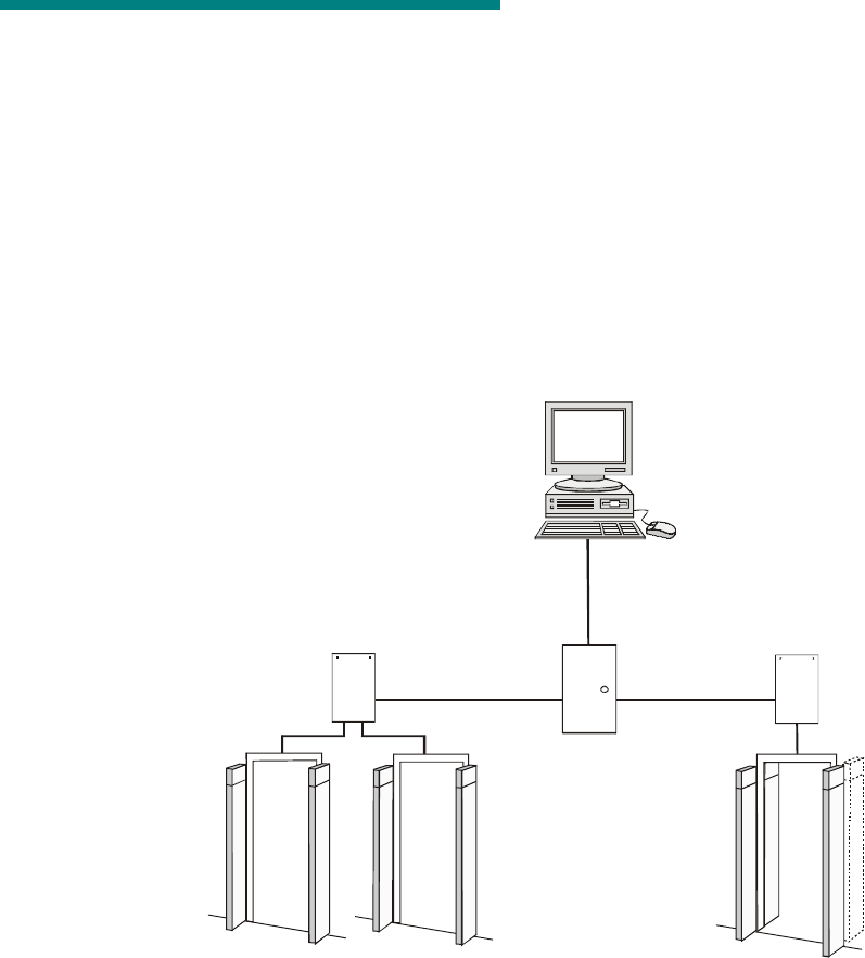
Figure 1. C•CURE Watch System Configuration
RF Controller RF Controller
Panel
C•CURE 800 Host
4-RF Antenna
Configuration
2-RF Antenna
Configuration
2-RF Antenna
Configuration

C•CURE Watch Installation and Service Guide 2-3
RF Controller Block
Synchronization Circuitry
The synchronization circuitry (7) consists of one
input and one output channel using the RS-422
differential communications protocol. This circuitry
prevents interference from other RFID components
in the area by synchronizing transmit/receive
signals.
Synchronization establishes a daisy-chain
connection between RF controllers operating in
close physical proximity to each other. Every RF
controller operating within 152m (500ft) of another
RF controller must be included in the wiring
configuration (even if they are part of a separate
C•CURE 800 system).
The wiring configuration establishes the first RF
controller in the daisy chain as the primary
controller. The first RF controller in the chain is
identified based on the lack of an input
synchronization signal at the synchronization port
(7). All other RF controllers in the synchronization
daisy chain operate as secondary controllers.
Synchronization circuitry operates automatically
based on installation configuration and system
status:
• RF controller offline
When the RF controller is not powered on or is
being reset, the synchronization signal is
passed straight through to other RF controllers
in the system.
• RF controller initialization
When an offline or reset RF controller begins
operating, the synchronization signal continues
to be passed through to other RF controllers
while the system monitors the input signal.
The monitoring process enables the hardware
to determine whether this RF controller is a
primary or secondary controller.
The RF controller checks for proper
synchronization polarity. If synchronization
wiring is incorrect, the RF controller locks up
and the on-board status LEDs flash an error
code.
• Primary controller operation
If initialization establishes the RF controller as
the primary controller, it generates a
synchronization signal and sends it to the next
RF controller (if any).
• Secondary controller operation
If initialization establishes the RF controller as
a secondary controller, it synchronizes
operation of this RF controller and sends the
synchronization signal to the next RF controller
(if any).
Communications Interfaces
The communications interfaces include the
following:
• RS-485
The RS-485 communications interface controls
the flow of information between the apC and
the CID controller. The half-duplex interface
limits communication to one direction at a time.
The RS-485 interface currently is set by the
system software to operate at 9600 baud, eight
data bits, no parity, no flow control, and one
stop bit.
• On-board Digital Signal Processor (DSP) LEDs
DS1—Flickers when a valid detection occurs.
DS4–Flickers when a partial detection occurs.
A partial detection may be caused by
interference.
2-4 8000-2803-01, Rev. 1/A Basic Functionality

C•CURE Watch Installation and Service Guide 3-1
Chapter 3
Planning
In This Chapter
RF Passage Reader Configurations........................................................................... 3-2
Single-Antenna Configurations ............................................................................ 3-2
Multiple-Antenna Configurations.......................................................................... 3-2
Application-Specific Configuration Requirements................................................ 3-2
Coordinating with Software Features ......................................................................... 3-3
Configuration Requirements....................................................................................... 3-3
RF Passage Antennas ......................................................................................... 3-3
RF Controllers ...................................................................................................... 3-4
Inputs ................................................................................................................... 3-4
Outputs................................................................................................................. 3-4
Host Panel............................................................................................................ 3-4
RF Controller Power Supply................................................................................. 3-4
External Power (to Power Supply) ....................................................................... 3-4
Cabling ................................................................................................................. 3-5
Asset Tag ............................................................................................................. 3-6
Access Control Badge ......................................................................................... 3-6
Tools and Equipment.................................................................................................. 3-6
3-2 8000-2803-01, Rev. 1/A Planning
RF Passage Reader
Configurations
An RF passage reader protects a door or portal by
detecting badges and/or tags. An RF reader is
represented by a combination of hardware
components: an RF controller and one or more RF
passage antennas.
Since an RF controller accepts input from up to
four antennas, one RF controller can represent up
to four RF readers. Some RF readers use a single
RF antenna while others consist of one or two
antenna pairs.
Single-Antenna Configurations
In some circumstances, a single RF antenna can
be used to protect a door. In this configuration, one
RF controller can represent one, two, three, or four
RF readers.
Multiple-Antenna
Configurations
In many cases, more than one RF passage
antenna is required to protect a door/portal.
Multiple antennas are always installed in pairs—
one on the left side of the door/portal and one on
the right side. Users pass between the antennas in
a pair when they walk through the door/portal. In
multiple-antenna configurations, one RF controller
can represent one or two RF readers.
In many configurations, antennas in an antenna
pair are connected above and below the door to
form a wire loop.
Two RF passage antenna models are available to
maximize performance for multiple-antenna
configurations: Model A antennas and Model B
antennas. Model A antennas are optimized to
detect badges and Model B antennas are
optimized to detect tags. Antenna pairs are always
configured with two antennas of the same model. A
pair cannot be configured using one Model A and
one Model B antenna.
Application-Specific
Configuration Requirements
The number, model, and placement of RF passage
antennas varies based on whether or not the
system is to be used for asset management.
Hands-Free Access Control
Requirements
Hands-free access control systems do not detect
assets. The following requirements apply:
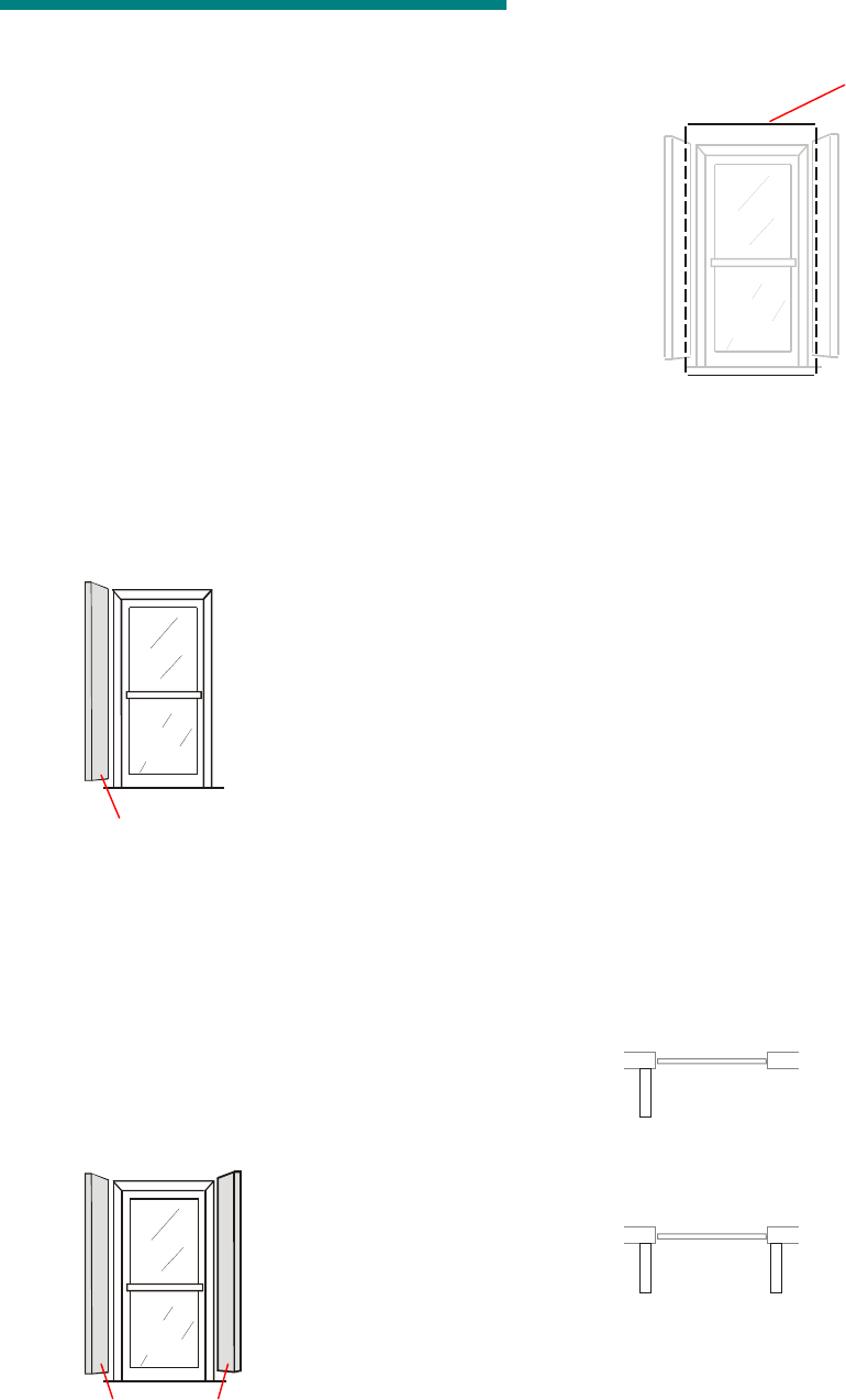
• A single Model A RF passage antenna may be
used to protect doors up to .9m (3ft).
A
• A pair of Model A RF passage antennas may
be used to protect doors up to .9m (3ft). The
wire loop is optional for this configuration.
AA AA
Antenna Pair
Wire Loop
Antenna
C•CURE Watch Installation and Service Guide 3-3
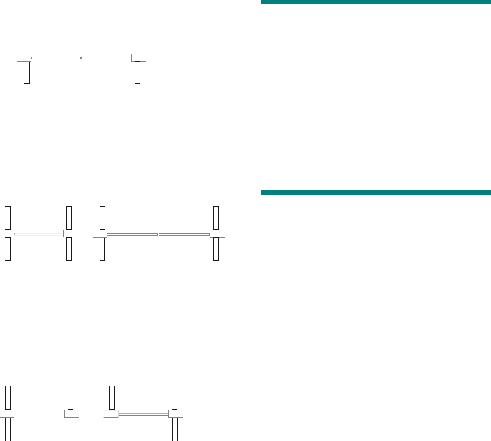
• A pair of Model A RF passage antennas is
required to protect doors between .9m (3ft) and
1.8m (6ft). The wire loop is required for this
configuration.
A A
Asset Management Requirements
RF passage readers that detect assets (whether
they detect assets and badges or assets only) are
always configured in multiple-antenna
configurations that include one pair of Model A
antennas and one pair of Model B antennas to
protect doors/portals up to 1.8m (6ft).
B
A A
B
A
A
B B
When a door that detects assets also secures an
area through the use of access control badges, the
Model A antenna pair is installed outside the
secured area. For doors/portals that detect assets
only (badges are not detected), it does not matter
which side has Model A and which side has Model
B antennas.
B
A A
B
B
A
A
B
A wire loop is required for doors/portals greater
than .9m (3ft) wide. At doors/openings that are .9m
(3ft) or less, a wire loop is optional.
Coordinating with Software
Features
The C•CURE 800/8000 application provides
several features that require specific hardware
components or configurations including:
• Asset/badge linking requires that systems be
configured with four RF passage antennas at
secured doors/portals.
• Check out feature requires that RF readers be
configured with PIR or other exit detection
devices.
Configuration Requirements
Configuration requirements provide information
needed when selecting hardware components and
planning the installation. Requirements are
provided for the following:
• RF passage antennas
• RF controllers
• Host panel (apC or iStar)
• RF controller power supply
• External power
• Cabling
• Asset tag
• Access control badge
RF Passage Antennas
• See Cabling on page 3-5 for maximum cable
distance between RF passage antennas and
RF controller.
• A wire loop is recommended for antenna pairs
when they are installed at doors/portals greater
than .9m (3ft) wide. A wire loop is optional for
antenna pairs installed at doors/portals that are
.9m (3ft) or less.
Note: The wire loop generally enhances RF
antenna performance. Occasionally,
environmental noise conditions can cause the
wire loop to degrade performance.
Secured
Area
Secured
Area
Placement of Model A and Model B
Antennas Not Critical if Opening Not
Controlled by Badges
Model A Antennas Outside Secured Area
at Doors Controlled by Badges
3-4 8000-2803-01, Rev. 1/A Planning
• Check installation sites for potential noise
sources:
– Whenever possible, remove noise sources
such as computer monitors, TVs, switching
power supplies, and neon displays from
within 1.8m–2.4m (6ft–8ft) of antennas.
– Whenever possible, remove large metal
office furniture such as desks, filing
cabinets, book shelves, and waste baskets
from within .6m–.9m (2ft–3ft) of antennas.
– Avoid installing passage antennas where
metal construction materials (recessed
door frames, corner beading) are adjacent
and parallel to flat side of antenna.
RF Controllers
• The enclosure must be mounted in a protected
location such as: above ceiling tiles, in a utility
room, or in a basement. The RF controller
must be installed within the following cable
distances from other system components:
– 61m (200ft) of RF passage antennas
– 30m (100ft) of power supply
– 305m (1000ft) of host panel
Note: Cable specifications vary based on the
distance between components. Select the
correct cable for each installation.
• Select a mounting location that provides
adequate space for installation and service.
The enclosure is approximately 28cm (11in)
high, 22.5cm (8.9in) wide, and 5.4cm (2.2in)
deep.
– When possible, select an installation site
that DOES NOT impede traffic during
installation and servicing.
– Select an installation site that enables
direct conduit runs and cable runs, without
causing cable routing problems. All cables
except power enter the enclosure from the
top.
– Power cables must enter enclosure from
the bottom knockout.
Inputs
Two supervised inputs are provided. These inputs
are automatically associated with antenna 1.
Outputs
The outputs provide 12V open circuit or 10V at
10mA. These outputs are automatically associated
with antenna 1.
Host Panel
• Connect to a dedicated line controlled by an
easily accessible power switch.
• Maximum cable distance from the panel to an
RF controller is 305m (1000ft).
RF Controller Power Supply
Note: External power supply not evaluated by UL
(see electrical specifications in Chapter 1:
Introduction.
• For external power sources, 15Vdc linear
power supply is recommended.
• Maximum distance from power supply to RF
controller is approximately 30m (100ft) (see
Cabling on page 3-5).
• North America: requires a nominal 15V Class
2 linear power supply.
• EU: This product runs on 15Vdc linear power
supply. In the EU, it is intended to be powered
from a Limited Power Source. A limited power
source is a certified source of SELV, and if
inherently limited, with 8 amps maximum
output current, and a maximum of 100VA
available; or if not inherently limited, fused with
a maximum value of 3.3 Amps, meeting
section 2.11 of IEC950, and a maximum of
250VA available. The power supply can be
obtained through Sensormatic or through
another source where the provider can furnish
the verification. This is required to assure
electrical safety in the product.
External Power (to Power
Supply)
The ac source to the RF controller power supply
must be unswitched with less than 0.5Vac between
neutral and ground. DO NOT share the ac source
with neon signs, motors, computers, cash
registers, terminals, or data communications
equipment.
DO NOT use orange-colored outlets dedicated for
computer equipment.

C•CURE Watch Installation and Service Guide 3-5
Cabling
General cabling guidelines:
• A single common ground is required for all
system components.
• All wiring that runs through a plenum area
must be plenum rated.
• RF controller cabling should not share conduit
with mains line power cabling.
• All exposed wiring must be concealed with
raceway or similar cabling protection.
• apC/iStar RS-485 cable runs of exceptional
distance may require Belden 9842, which IS
NOT plenum rated.
• Synchronization cabling is required for RF
controllers located within 152m (500ft) of each
other, even when they are not connected to the
same system.
• Passage antenna wire loop may be exposed to
corrosive cleaning fluids; cable jacket MUST
be composed of a fluoropolymer such as FEP
Teflon or Kynar with a thickness of .3mm
(.015in.).
Wire Use Wire Type Specification Star
Con.
Daisy
Chain
Maximum
Distance
RF Controller Sync to
common terminal block
(add’l wire may be needed
between terminal blocks)
2 or 4 conductor / 22 AWG,
shielded
Belden 82723 or equiv. No Yes 305m (1000ft)
RS-485 between panel and
RF controller (are there
differences between apC
and istar?)
2 conductor / 22 AWG, shielded Belden 82761 or equiv. Yes Multi
Drop
305m (1000ft)
RF Controller to RF
Passage Antenna
(Signal/Control)
8 conductor / 22AWG, shielded
8 conductor / 18AWG, shielded 23m (75ft)
8 conductor / 16AWG, shielded 38m (125ft)
8 conductor / 14AWG, shielded 61m (200ft)
RF Controller to RF
Passage Antenna (Power)
2 conductor / 20AWG, shielded 15m (50ft)
2 conductor / 18AWG, shielded 23m (75ft)
2 conductor / 16AWG, shielded 38m (125ft)
2 conductor / 14AWG, shielded 61m (200ft)
Wire Loop for RF Passage
Antenna Pairs
1 conductor / 18 AWG, DO NOT
use shielded wire, cable jacket must
be composed of a fluoropolymer
with a thickness of .3mm (.015in.)
N/A N/A 3m (10ft)
RF Controller to Inputs 2 conductor / 22 AWG, shielded Belden 82761 or equiv. N/A N/A 305m (1000ft)
RF Controller to Outputs 2 conductor / 18 AWG, shielded Belden 82760 or equiv. N/A N/A 305m (1000ft)
RF Controller to External
Power Supply
2 conductor / 20AWG, shielded 6m (20ft)
2 conductor / 18AWG, shielded 11m (35ft)
2 conductor / 16AWG, shielded 18m (60ft)
2 conductor / 14AWG, shielded 30m (100ft)
RF Controller ac Power
Cord
Type SJ or SJT / 18AWG 250V
rated (power cord connection not
evaluated by UL)
1.8m (6ft)
minimum
Chassis Ground Wire multi-stranded / 16AWG 250V 1.8m (6ft)
Note: To maintain UL Listing, field wiring shall not be less than 22AWG.

3-6 8000-2803-01, Rev. 1/A Planning
Asset Tag
Note: Asset tags have not been evaluated by UL.
Allow two hours for the adhesive to set, ensuring a
bond to the asset’s surface that will not be easily
compromised. Complete application instructions
are provided in Appendix A: Asset Tag
Installation.
Access Control Badge
Access control badges and badge format
(RFID 56) must be defined in the host system
before use.
Tools and Equipment
The installation process may vary based on
construction materials and hardware components.
The following tools and equipment may be required
to install this system:
• Digital voltmeter (DVM)
• Drill with 6.4mm (1/4in.) and 9.5mm (3/8in.)
bits
• Fish tape (snake)
• Hammer
• Hammer drill and masonry drill bits
• Hand vacuum and broom
• Hacksaw
• Jig saw (hand-held)
• Laptop computer running Microsoft® Windows®
• Level
• Permanent ink marker
• Plastic sheeting (to protect environment from
dust)
• Pliers, small needlenose
• PVC pipe-cutting tool
• Ratchet and socket set
• RJ-6/telephone crimping tool
• Saw (with diamond blade) for cutting floor
trench
• Screwdrivers (including Phillips screwdrivers)
• Wire crimper
• Wire cutters
• Wire stripper
C•CURE Watch Installation and Service Guide 8000-2803-01, Rev. 1/A 4-1
Chapter 4
Installation
In This Chapter
Installation Checklist................................................................................................... 4-2
Phase 1: Hardware Installation ............................................................................ 4-2
Phase 2: System Activation and Test .................................................................. 4-2
Install Cable Runs ...................................................................................................... 4-2
Install RF Passage Antennas ..................................................................................... 4-2
Prepare for Installation......................................................................................... 4-2
Install brackets and Mount Antennas................................................................... 4-3
Install Wire Loop for Antenna Pairs ..................................................................... 4-3
Connect RF Controller Cables ............................................................................. 4-4
Install Finishing Hardware.................................................................................... 4-5
Install RF Controller.................................................................................................... 4-5
Prepare for Installation......................................................................................... 4-5
Mount the RF Controller Enclosure...................................................................... 4-5
Connect RF Antenna Cables ............................................................................... 4-6
Connect Inputs and Outputs ................................................................................ 4-8
Connect Communications Cable ......................................................................... 4-9
Connect Sync Cable ............................................................................................ 4-9
Connect RF Reader at Panel ................................................................................... 4-10
Connect Power to RF Controller............................................................................... 4-10
Connect Model CW-RID-1 to AC Power............................................................ 4-10
Connect Model CW-RID-XPS to External Power SupplyError! Bookmark not
defined.
Inspect Installation.................................................................................................... 4-12
Apply Power.............................................................................................................. 4-12
Verify System Operation........................................................................................... 4-12
Functional Test................................................................................................... 4-12
Full System Test ................................................................................................ 4-13

4-2 8000-2803-01, Rev. 1/A8000-2803-01, Rev. 1/A8000-2803-01, Rev. 1/A8000-2803-01, Rev. 1/A Installation
Installation Checklist
This check list provides an overview of the steps
required to install C•CURE Watch components.
Since order of installation can vary somewhat
based on site requirements, the check list
establishes guidelines concerning the relative order
in which they may be completed.
Site planning should be completed before
beginning the installation.
WARNING: Do not install this product in
hazardous areas where highly
combustible or explosive products are
stored or used.
Phase 1: Hardware Installation
G Install cable runs.
– Cable requirements overview, page x
– RF passage antenna cabling, page x
– RF controller cabling, page x
G Install RF antennas, RF controllers, door
hardware (door latch relay, door sense
monitor, request to exit, passive infrared
detector).
G Install RF controller, page x.
– Mount RF controller enclosure, page x
– Connect power supply cables, page x
– Connect RF antenna cables, page x
– Connect inputs and outputs, page x
– Connect communications cables, page x
– Connect synchronization cables, page x
G Connect to host panel (apC or I-Star), refer to
installation instructions supplied with panel.
G Connect power to RF controller, page x.
Phase 2: System Activation and
Test
All steps in Phase 1 must be completed before
beginning Phase 2. Complete these steps in the
order presented.
G Inspect the installation, page x.
G Activate the system, page x.
– Tune RF passage antennas, page x
– Configure C•CURE 800 software, page x
G Verify system operation, page x.
Install Cable Runs
Tag all wire bundles and run cables.
Pull a little extra wire to place less strain at the
connection points (excess wire can be coiled into
the wall space).
Required cable runs include:
• RF controller to door/portal being protected.
• Host panel to RF controller.
• RF controller to RF controller (for
synchronization).
• Power to RF controller.
Refer to Chapter 3: Planning for more specific
cable specifications.
Install RF Passage
Antennas
Installing RF passage antennas includes the
following:
• Prepare for installation
• Install brackets and mount antennas
• Install wire loop (for antenna pairs)
• Connect RF controller cables
• Install finishing hardware
Prepare for Installation
The following items are required before installation
begins:
• Site plan indicating model of each RF passage
antenna and its mounting location.
• Two cables run between RF antenna mounting
location and RF controller mounting location:
control cable and power cable.
!
C•CURE Watch Installation and Service Guide 8000-2803-01, Rev. 1/A 4-3
RF Passage Antenna Kit (0351-2180-01)
Description Qty. Part No.
Top Bracket, Passage Antenna 1 0500-5026-01
Butt Splice, FULLINS, 22-16 2 2141-0003
Screws, SDRL 8 x 1/2, PHP, S304 16 2816-7669-01
Anchors, MLY, 8-10, W/PH SCR, 7/8”L 16 2880-0097-01
Wire, HK, 18G, 19x30, TFE, Black 8 6018-0012-01
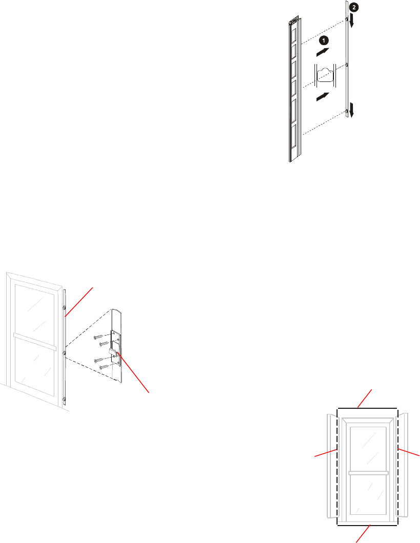
Install brackets and Mount
Antennas
1. With bracket tabs facing up, press bracket
against door frame or wall with bottom of
bracket 17cm (6.75in.) above floor.
Position bracket perpendicular to floor.
Antennas that comprise a pair must be
mounted parallel to each other on opposite
sides of door/opening.
2. Mark and drill mounting screw holes.
Note: Mount bracket using holes adjacent to
mounting tabs. Holes at top and bottom of
mounting bracket are not used at this time (you
may want to pre-drill for later use).
3. Mount antenna bracket using appropriate
mounting hardware from install kit.
4. With antenna’s mounting surface facing
bracket, align three openings over bracket
tabs, press antenna against bracket (1), then
slide antenna down (2) until it is secure.
5. Determine where cables will exit wall/ceiling
and drill holes. Fish required cables through
appropriate holes.
Install Wire Loop for Antenna
Pairs
Installation of a wire loop is optional. Check with
project manager to determine if wire loop is
required.
Each RF passage antenna includes a loop wire
that runs the length of the antenna, exiting at the
top and bottom (near the mounting bracket). A wire
loop is created when the loop wires of an antenna
pair are connected to each other above and below
the door/portal.
Exposed wire loop wiring may be concealed with
raceway and/or placed under the doorway
threshold. In some cases it may be necessary to
conceal the lower connecting wire within a floor
trench.
Mounting Bracket
Mounting Tab
Loop Wire
in Passage
Antenna
Loop Wire
in Passage
Antenna
Connecting Wire
Completes Wire Loop
Connecting Wire
Completes Wire Loop
4-4 8000-2803-01, Rev. 1/A8000-2803-01, Rev. 1/A8000-2803-01, Rev. 1/A8000-2803-01, Rev. 1/A Installation
1. Remove door threshold, and determine if there
is adequate clearance to place connecting wire
under it without cutting a floor trench.
2. If necessary, cut floor trench (0.3cm [1/8in.]
wide by 1.2cm [1/2in.] deep).
3. Locate ends of loop wire tucked into frame at
top and bottom of each antenna.
Note: Remove bottom cap to retrieve wire
loop, feed through opening in cap, and re-
install cap.
4. Cut two pieces of wire to complete wire loop
above and below door/portal (connecting
wires).
5. Run top connecting wire above door/portal and
connect to antenna wire at top of each
antenna.
6. Run bottom connecting wire under doorway.
Conceal by replacing threshold or sealing
trench being careful not to pinch wire.
7. Connect to antenna loop wire at bottom of
each antenna.
The wire loop is installed and ready to operate.
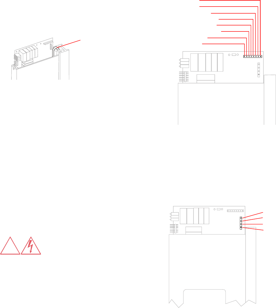
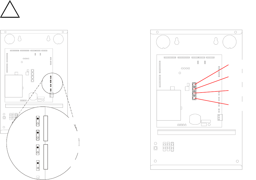
Connect RF Controller Cables
WARNING: RISK OF ELECTRIC
SHOCK! Read manual before
servicing.
1. Connect 8-conductor control cable from RF
controller to terminal block on the RF antenna
board as follows:
Pin Function
Pin 1 RX–
Pin 2 RX+
Pin 3 Red LED
Pin 4 Amber LED
Pin 5 Green LED
Pin 6 LED Ground
Pin 7 TX
Pin 8 N/C
2. Connect terminal block to control connector P2
(pin 1 is at outside edge of board).
3. Connect 2-conductor power cable to terminal
block as follows:
Pin Function
Pin 1 +16Vdc
Pin 2 Return
Pin 3 Unused
Pin 4 Unused
4. Connect terminal block to power connector P1
(pin 1 is at bottom).
Note: See Chapter 5: Service for information
about verifying and optimizing antenna
performance.
1: RX–
2: RX+
3: Green LED
4: Amber LED
5: Red LED
6: LED Ground
7: TX
8: N/C
4: Unused
3: Unused
2: Return
1: Vcc
!
Loop Wire
C•CURE Watch Installation and Service Guide 8000-2803-01, Rev. 1/A 4-5
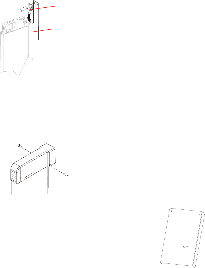
Install Finishing Hardware
1. Insert stabilizing brackets as shown below, one
at top and one at bottom of antenna. Attach to
mounting bracket with two screws.
2. Install antenna top cap.
Place top cap over antenna interface board
starting at front. Position LED window over
LEDs. A pin inside cap front seats in antenna
cover beneath LEDs. Secure at sides with two
screws.
DO NOT leave antenna components exposed
for extended periods.
3. Install raceway to conceal exposed wiring.
Install RF Controller
Installing RF controller includes the following:
• Prepare for installation
• Mount the RF controller enclosure
• Connect RF antenna cables
• Connect inputs and outputs
• Connect power supply cable
• Connect communications cable
• Connect sync cable
Prepare for Installation
The following items are required before installation
begins:
• Site plan indicating:
– Installation site of RF controller
– Installation sites of RF antennas and
associated reader addresses
– Inputs and outputs associated with
antenna 1 (optional)
– Installation site of host panel
– Installation site of power supply enclosure
– Optional inputs and outputs are to be
connected to antenna 1.
– Installation site of common terminal block
for RF controller synchronization.
• Two cables (one control and one power) run
between RF antennas and RF controller.
• Optional — cable run between each required
input and output and RF controller.
RF Controller Install Kit (0351-2160-01)
Verify contents of kit before beginning installation.
Description Qty. Part No.
Plastic Anchors, 10-12, 1”L, w/scr 4 2880-0098-01
Template, C•CURE Watch RFID Contrlr 1 8000-2820-01
Install and Service Guide 1 8000-2803-01
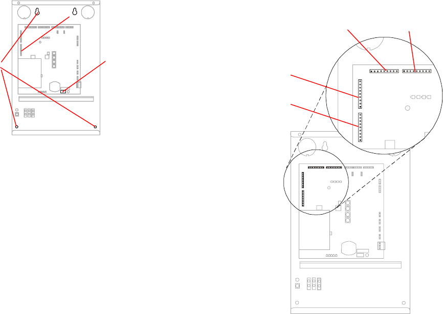
Mount the RF Controller
Enclosure
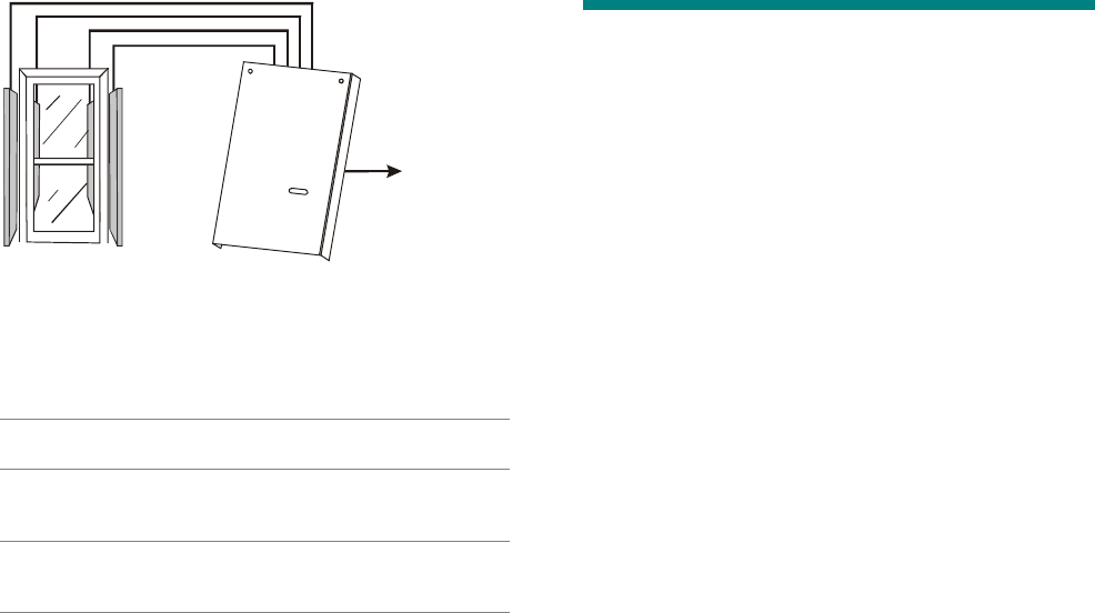
1. Remove screws that secure enclosure cover.
Remove cover by pulling forward slightly at top
and slip cover straight up until cover is free of
the retaining tab at bottom of enclosure.
Mounting Bracket
Stabilizing Bracket
4-6 8000-2803-01, Rev. 1/A8000-2803-01, Rev. 1/A8000-2803-01, Rev. 1/A8000-2803-01, Rev. 1/A Installation
2. Verify that On/Off switch is in off position.
NL
3. Hold enclosure in its mounting location and
mark position of mounting screws (4) at
openings in back of enclosure.
4. Drill holes for screws and install wall anchors if
required. Insert top screws and tighten until
almost flush with wall.
5. Slip enclosure over screws and slide down to
lock screws in keyhole openings.
6. Tighten top screws. Insert bottom screws and
tighten.
Connect RF Antenna Cables
RF antenna cable connections differ depending on
whether RF proximity or RF passage antennas are
used.
Connecting RF Proximity Antenna Cables
RF proximity antennas are not available at this
time.
Connecting RF Passage Antenna Cables
The following steps must be completed for each
RF antenna connected to this RF controller.
1. Connect 8-conductor control cable from RF
antenna to 9-pin terminal block on RF
controller as follows:
Pin Function
Pin 1 Shield
Pin 2 RX–
Pin 3 RX+
Pin 4 Red LED
Pin 5 Amber LED
Pin 6 Green LED
Pin 7 LED Ground
Pin 8 TX
Pin 9 N/C
2. Connect terminal block to appropriate antenna
control connector (pin one is solid).
NL
Note: The RF controller provides two
channels. One channel is associated with
antenna connectors 1 and 2 and the other
channel is associated with antenna connectors
3 and 4.
Always connect the two antennas that
comprise a pair to the same channel.
Antenna Connector Channel
Antenna 1 First Channel
Antenna 2 First Channel
Antenna 3 Second Channel
Antenna 4 Second Channel
3. Connect 2-conductor power cables from RF
antennas to 4-pin terminal blocks as follows.
Always combine antennas 1 and 2 on one
connector and antennas 3 and 4 on the other.
Pin Function Connector Antenna
Pin 1 Return P24
Pin 2 +16Vdc P23 Antenna 1 or 2
Pin 1 Return P22
Pin 2 +16Vdc P21 Antenna 3 or 4
Antenna 1Antenna 2
Antenna 3
Antenna 4
On/Off Switch
Mounting
Holes
C•CURE Watch Installation and Service Guide 8000-2803-01, Rev. 1/A 4-7
!
4. Connect Connect terminal block to appropriate
antenna power connector.
CAUTION: System failure may
result if antennas are not connected
as specified below.
NL
5. Set antenna address switches. Multiple RF
passage antennas configured as part of the
same RF reader must have corresponding
address switches set to same address.
Important: Set address switches for
unconnected antennas to 0.
NL
Antenna 1
Antenna 2
Antenna 3
Antenna 4
P21 / Antenna 4
Return
Power
P22 / Antenna 3
Return
Power
P23 / Antenna 2
Return
Power
P24 / Antenna 1
Return
Power
4-8 8000-2803-01, Rev. 1/A8000-2803-01, Rev. 1/A8000-2803-01, Rev. 1/A8000-2803-01, Rev. 1/A Installation
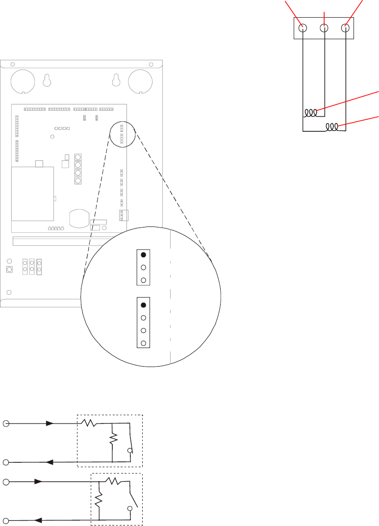
Connect Inputs and Outputs
The RF controller provides connections for two
inputs and two outputs. These inputs and outputs
must be associated with the opening/portal
connected to the Antenna 1 connector.
NL
Inputs must be supervised. All inputs and outputs
are configured from the host system. Inputs must
be wired as shown below.
The output connector provides internal power for
both outputs. These must be wired in series.
Outputs provide 10 milliamps at 10V and 12V open
circuit.
Input 2
Output 2
Output 1
Return 1
+12Vdc
Input 1
Output 2
Output 1
Return 2
Supervised,
Normally Closed
Supervised,
Normally Open
Output
2
Output
1
+12Vdc
Circuit protected
outside dotted line.
Circuit protected
outside dotted line.
1K
1K
1K
1K
P19
P20
C•CURE Watch Installation and Service Guide 8000-2803-01, Rev. 1/A 4-9
Connect Communications Cable
The RF controller provides two RS-485 connectors
for configuration flexibility. RF controllers may be
daisy-chained to the host panel. In addition to RF
controllers, input/output boards may also be
included in the daisy chain.
1. Connect 2-conductor or 4-conductor, shielded
cable to 5-pin terminal block.
Pin Function
Pin 1 TX/RX
Pin 2 TX/RX
Pin 3 RX
Pin 4 RX
Pin 5 Shield
Note: Connection depends on RS-485
implementation. For 2-conductor, half-duplex
mode connect to TX/RX pins. This mode
operates at 9600 baud. For 4-conductor, full-
duplex mode use the TX/RX pins for transmit
and the RX pins for receive.
2. Connect communications cable from panel,
another RF controller, or input/output board to
connector P18 or P36.
NL
3. Do one of the following:
– If another device, is to be connected to this
RF controller, connect additional
communication cable to 5-pin terminal
block and connect to the available RS-485
connector (P18 or P36).
– If a connection terminates at this RF
controller, the shield must be connected to
a chassis ground instead of the RS-485
connector (P18 or P36).
In addition, pins one and two must be
jumpered on the associated termination
jumper.
Connector Jumper Terminated Unterminated
P18 P10 Pins 1 / 2 Pins 3 / 4
P36 P17 Pins 1 / 2 Pins 3 / 4
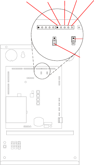
Connect Sync Cable
RS-422 synchronization (sync) cabling coordinates
transmit and receive signals on a system-wide
basis to eliminate system-generated interference.
ALL RF controllers must be installed with sync
cabling, even if they are associated with different
host systems. Call Technical Support for
synchronization guidelines regarding RF controllers
installed in separate buildings.
Sync cabling establishes a single daisy-chain
connection for all RF controllers. The daisy chain is
installed through one or more common terminal
blocks.
P10 (Shown
Terminated)
P17 (Shown
Unterminated)
RX
P18 P36
TX/RX RX Shield
TX/RX
4-10 8000-2803-01, Rev. 1/A8000-2803-01, Rev. 1/A8000-2803-01, Rev. 1/A8000-2803-01, Rev. 1/A Installation
Sync cabling establishes one RF controller as
primary and all others as secondary. The first RF
controller in the sync cabling daisy chain becomes
the primary RF controller.
NL
The following guidelines must be observed:
• Sync cabling connects to P34.
• Input terminals are not connected on primary
RF controller. Output terminals are not
connected on last secondary RF controller in
daisy chain.
• Polarity MUST BE strictly observed (output– to
input– and output+ to input+).
To connect sync cable to RF controller:
1. Remove jacket and metal shielding from end of
sync cable, leaving enough to connect to P34.
2. Connect wires to 6-pin terminal block that
mates to P34 on RF controller.
Pin Signal
Pin 1 Open
Pin 2 Input, –
Pin 3 Input, +
Pin 4 Shield
Pin 5 Output, –
Pin 6 Output, +
3. Connect terminal block to P34.
Connect RF Reader at Panel
Connect the RF Reader to the host panel using
instructions provided by the manufacturer.
Note: Shield in RS-485 cable must be connected
to chassis ground at panel.
Connect Power to
RF Controller
The RF Controller is available in two models:
• Model CW-RID-1 is hard-wired to ac power. It
includes a universal power supply (Eos model
VLT 130-1002).
• Model CW-RID-XPS requires an external
power supply.
WARNING: RISK OF
ELECTRIC SHOCK! Be sure
power is off before connecting
components.
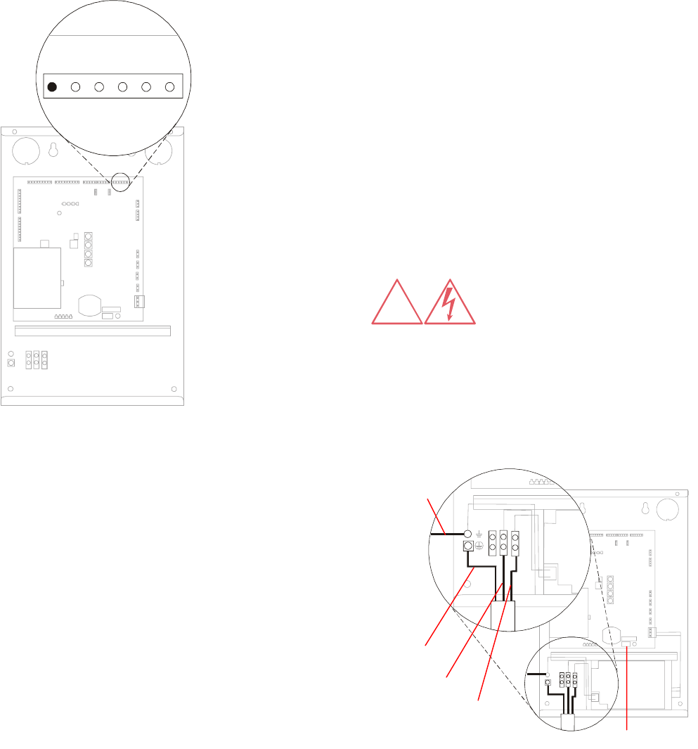
Connect Model CW-RID-1 to AC
Power
This model may be hard wired or connected using
a line cord.
NL
NL
Hard Wired Connection
This step must be performed by a licensed
electrician in accordance with National Electric
Code and applicable local codes.
!
Out +
Out –
Shield
In +
In –
Open
P34
Neutral
Line
PE
On/Off Switch
Chassis
Ground Wire

C•CURE Watch Installation and Service Guide 8000-2803-01, Rev. 1/A 4-11
CAUTION: A 10A, 2 pole, ganged
disconnect device, which also provides
short circuit and overload protection, and
has a minimum 3mm open circuit
clearance, in accordance with the
National Electric Code and applicable
local codes must be installed by a
licensed electrician at a location readily
accessible to the equipment.
Ein 10A, 2-poliges, gekoppeltes
Ausschalt-gerät, welches auch über
einen Kurzschluß- sowie
Überbelastungsschutz verfügt, und einen
minimum 3mm offenen Schaltabstand
aufweist, nach Übereinstimmung mit den
Nationalen Elektrischen Regelungen
sowie lokalen Regeln, muß an einem
Standort installiert werden, welcher
einfachen Zugang zum Gerät erlaubt.
1. Verify that RF controller is turned off.
2. Use knockout at bottom left corner of
enclosure to access the power connector.
3. Connect incoming ac wires to the connector for
115Vac or 230Vac operation based on the
following:
NAa Europe Pin Function
Green/Yellow Green/Yellow PE Ground
White Blue N Neutral
Black Brown L Line
4. For FCC compliance, a chassis ground wire is
required. Connect chassis ground wire from a
building ground (such as pipes or conduit) to
the chassis ground terminal in the RF
controller enclosure. Use 16AWG 250V multi-
stranded wire with maximum length 1.8m (6ft).
Cord Connection
Use one of the following installation kits.
Power Cord (NA)
Description Qty. Part No.
Txxx 1 0xxx-xxxx-01
Txxx 1 0xxx-xxxx-01
Power Cord (EU)
Description Qty. Part No.
Txxx 1 0xxx-xxxx-01
Txxx 1 0xxx-xxxx-01
CAUTION: For installation using a line
cord, the socket-outlet must be installed
near the equipment and at a location
which is easily accessible.
Für Installationen mit einem Stromkabel
muß die Steckdose an einem Standort
installiert werden, welcher einfachen
Zugang erlaubt.
1. Verify that RF controller is turned off.
2. Tighten strain relief into conduit knockout at
bottom of enclosure.
3. Thread power cord through strain relief and
secure.
4. Connect incoming ac wires to the connector for
115Vac or 230Vac operation based on the
following:
NA Europe Pin Function
Green/Yellow Green/Yellow PE Ground
White Blue N Neutral
Black Brown L Line
5. For FCC compliance, a chassis ground wire is
required. Connect chassis ground wire from a
building ground (such as pipes or conduit) to
the chassis ground terminal in the RF
controller enclosure. Use 16AWG 250V multi-
stranded wire with maximum length 1.8m (6ft).
!
!
4-12 8000-2803-01, Rev. 1/A8000-2803-01, Rev. 1/A8000-2803-01, Rev. 1/A8000-2803-01, Rev. 1/A Installation
Inspect Installation
A final inspection of the installation should be
conducted before applying power to the system.
1. Verify that the RF controller power switch is
turned Off.
NL
2. Inspect RF controller, host panel, power supply
enclosures, and wiring connections:
– Remove metal shavings and other
installation debris from enclosures.
– Verify that all connections are secure.
Apply Power
1. Provide power to the RF controller.
2. Turn the RF controller power switch On.
Verify System Operation
There are two levels of system verification:
• Functional test of RF controller and RF
antenna does not require connection to panel.
• Full system test requires connection to panel
and configuration of host system.
Functional Test
The functional test consists of an RF antenna LED
test and a signal detection test.
RF Antenna LED Test
1. Verify that rotary switches have been set for
this antenna configuration.
2. Record rotary switch settings.
3. Change rotary switches to 9-1-1-9.
4. Turn RF controller Off, then On to activate test
mode. It may take a short time for the test to
begin.
Green, amber, and red LEDs on all antennas
connected to this controller should light in
sequence.
5. Set rotary switches back to original
configuration or to setting for signal detection
test.
6. Turn RF controller Off, then On for settings to
take effect.
RF Antenna Signal Detection Test
1. Verify that rotary switches have been set for
this antenna configuration.
2. Record rotary switch settings.
3. Change rotary switches to 9-1-0-9.
4. Turn RF controller Off, then On to activate test
mode. It may take a short time for the test to
begin.
The RF antenna LEDs should remain off until a
badge or tag is detected. Detection of a badge
or tag should activate the amber LED. Blinking
of the LED indicates a weak detection.
5. Set rotary switches back to original
configuration.
6. Turn RF controller Off, then On for settings to
take effect.
On/Off Switch
C•CURE Watch Installation and Service Guide 8000-2803-01, Rev. 1/A 4-13
Full System Test
The full system test requires configuration of the
C•CURE 800/8000. To add an RF reader to the
host system, refer to the C•CURE 800/8000
Administrator’s Guide (UM-028) and the C•CURE
800/8000 Asset Manager User’s Guide (UM-033).
To verify system operation you must configure the
following software parameters:
• Configure C•CURE Watch readers.
• Define tag and card formats.
• Define tags and cards to be tested.
Based on system configuration, test each opening
with tags and/or badges. Verify that system
identifies and responds as expected based on
system configuration. Be sure to test the following:
• Detection of tags and/or badges.
• Read range of reader extends at least .9m (3ft)
in front of antennas.
• C•CURE 800 recognizes and reports detected
tags and badges.
• Inputs and outputs operate correctly.
Chapter 5: Service provides information on
troubleshooting system and antenna read range
problems.
4-14 8000-2803-01, Rev. 1/A8000-2803-01, Rev. 1/A8000-2803-01, Rev. 1/A8000-2803-01, Rev. 1/A Installation

C•CURE Watch Installation and Service Guide 5-1
Chapter 5
Service
In This Chapter
Parts List..................................................................................................................... 5-2
RFID 56 Format.......................................................................................................... 5-2
Tune RF Passage Antennas ...................................................................................... 5-2
DIP Switch Settings .................................................................................................... 5-4
Troubleshooting Tips .................................................................................................. 5-5
5-2 8000-2803-01, Rev. 1/A Service
Parts List
Description Product Code
C•CURE Watch RF Controller
with universal power supply CW-RID-1
RF Passage Antenna, Model A CW-ANT-PA
RF Passage Antenna, Model B CW-ANT-PB
C•CURE Watch Programmed Badge CW-FBRW-1
RFID 56 Format
The RFID 56 card format must be selected in the
Card Format window of C•CURE 800/8000. If it is
not an available choice, the following information
should be entered:
Identification
Name: RFID 56
Card Characteristics
Format Usage: Select Access control if this is
an access only installation.
Select Asset tracking if this is
an asset and access or an
asset only installation.
Type: Proximity
Field List
Field Type
Start
Length
Compl.
P. Start
P. Length
Shift
Facility Code 17 16 No 0 0 0
Card Number 33 24 No 0 0 0
Tune RF Passage Antennas
WARNING: RISK OF
ELECTRIC SHOCK! When
powered, high voltage exists on
the antenna board and at
tuning jumpers.
To optimize system performance, each RF
passage antenna must be tuned. The tuning
process uses six tuning jumpers to peak antenna
voltage.
Tuning Guidelines
RF passage antennas located within 4.6m (15ft) of
an antenna being tuned may interfere with the
tuning process (other passage antennas connected
to the same RF controller as antenna being tuned
DO NOT interfere with tuning). Interference is
possible even if antenna is connected to another
system or not connected to any system. Follow
these guidelines to eliminate the possibility of
interference:
• If interfering passage antenna can be moved,
place it further than 4.6m (15ft) from antenna
being tuned.
Tuning Procedure
Passage antennas are tuned while they operate. If
you have a partner, multiple antennas can be
tuned at the same time.
1. Turn Off RF controller power switch Off.
WARNING: RISK OF
ELECTRIC SHOCK! When
powered, high voltage exists on
the antenna board and at
tuning jumpers.
2. Verify the following before beginning:
– Antennas are completely installed and
connected to RF controller. This includes
wire loop if it is to be used.
– Power is available to RF controller.
3. Remove RF passage antenna top cap.
!
!
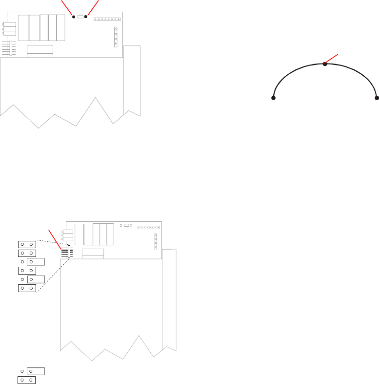
C•CURE Watch Installation and Service Guide 5-3
4. Place a digital dc voltmeter between test points
E3 (dc out) and E4 (ground).
5. Turn RF controller power switch On.
Add or remove jumpers to achieve maximum
voltage. See Set Tuning Jumpers on page 5-
3 for recommended tuning procedure.
Jumpers removed during tuning process
remain on tuning board in storage position.
BAR C ODE
Note: Tune to maximum voltage.
6. Test antenna performance by trying to read a
tag or badge in optimum orientation from at
least .9m (3ft) away. Red (badge) or amber
(tag) LED flashes when transponder is read.
If read range is less than .9m (3ft), refer to
Chapter 5: Service for troubleshooting
information.
7. Install antenna top cap after antenna is tuned.
Antenna is ready for operation.
Set Tuning Jumpers
The tuning process maximizes system
performance by ensuring that antennas receive the
maximum possible voltage. The various
combinations of tuning jumper positions represent
an impedance curve.
The procedure used to identify the optimum jumper
combination must take into account that any
particular combination of jumpers may be above or
below maximum.
The following recommended procedure uses the
least significant jumper to indicate whether antenna
is over or under tuned at each stage of the tuning
process. The procedure requires you to check the
position of each jumper, beginning with the bottom
jumper which represents the most significant bit
(MSB).
1. Attach voltmeter to test points. Voltage
measurements are taken throughout tuning
process.
2. Remove jumpers from all pin positions and
examine voltage at test points. Be certain to
wait a few seconds for voltage level to
stabilize.
3. Place jumper in pin position to be checked
(begin with position 1 at top). You are ready to
determine if this jumper remains In or Out:
If reading increases with jumper in, proceed to
step 4.
Or…
If reading decreases with jumper in, change
jumper being checked to Out position (storage)
and go to step 5.
4. Place another jumper on bottom pin position
(position 6–LSB). If reading increases with
jumper in, remove bottom jumper and go to
step 5. Jumper being checked remains In.
Or…
If reading decreases with jumper in, change
jumper being checked to Out position
(storage). Then, remove bottom jumper and go
to step 5.
=Stored Jumpe
r
=Installed Jumper
Tuning Jumpers
E3 (dc out) E4 (ground)
For illustration only. Actual
j
umper settings will vary.
Maximum Voltage
A
ll Jumpers
In
A
ll Jumpers
Out
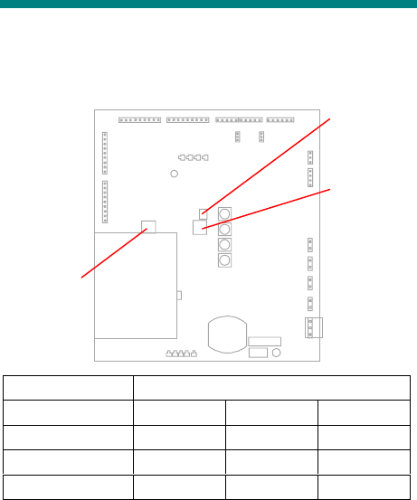
5-4 8000-2803-01, Rev. 1/A Service
5. Complete steps 3–5 for each pin position,
working from top to bottom. The next pin
position to check is pin position 2.
Note: Voltage level for satisfactory
performance is 18V±4V. See Chapter 5:
Service to troubleshoot an antenna that
cannot achieve voltage requirement.
DIP Switch Settings
The RF controller includes 3 DIP switches which
are factory set.
Switch DIP Switch Settings
123
S1 Off Off —
SW1 Off Off Off
MSW1 Off Off Off
S1
SW1
MSW1

C•CURE Watch Installation and Service Guide 5-5
Troubleshooting Tips
The following table contains suggested solutions
for problems that might be encountered in the
installation and operation of C•CURE Watch
system components.
Symptom Possible Cause Action
System does not power
on.
Defective power supply. Replace the power supply.
Blown fuse on the RF
controller board.
Replace with 5A., 250V fuse manufactured by
Semko or equivalent.
Power supply safety cutoff
input may be open.
If not using an external fire alarm, the safety
cutoff must be jumpered.
For installations using Sensormatic product
codes C2623-27 or C2626-27, jumper F1 and
F2 on the power supply.
System voltages are low. Low input voltage to power
supply.
Identify and eliminate the cause of the low input
voltage.
Green status LED (DS1
near On/Off switch) on RF
controller does not turn on
when either a badge or a
tag is present in antenna
field.
Antennas are not connected
to the RF controller.
Connect the antennas.
Antenna control cable not
connected to the RF
controller.
Connect the antenna control cables to the RF
controller.
High noise levels. Locate and eliminate noise source. Check
following:
1. Video or computer monitors within 3m (10ft).
2. Large electrical wireways.
3. Other EAS or access systems within 15.2m
(50ft).
4. Elevator motors.
5. RF controller not synchronized with other RF
controllers.
No antenna LEDs are
turned on.
Antenna control cable not
connected to the RF
controller.
Connect the antenna control cables to the RF
controller.
No voltage on the
antennas.
Antenna is not tuned correctly. Tune the antenna. See Tuning RF Passage
Antennas on page 5-2.
Cannot tune antenna or
antenna voltage is too low
(<14Vdc) when tuning.
Another RF passage antenna
may be located within 4.6m
(15ft) of antenna being tuned.
This does NOT apply to
antennas connected to same
RF controller as antenna
being tuned.
If possible, move antenna causing interference
so it is more than 4.6m (15ft) from antenna
being tuned.

5-6 8000-2803-01, Rev. 1/A Service
Symptom Possible Cause Action
Antenna is located near a
metallic object.
Remove the metallic object. Reposition the
antenna, if possible.
Antenna is not tuned correctly. Tune the antenna. See Tune RF Passage
Antennas on page 5-2.
Antenna voltage
measurement is
fluctuating.
Antenna is located near a
metallic object.
Remove the metallic object. Reposition the
antenna, if possible.
Possible noise source in the
area, such as a computer
monitor or ac power source.
Remove the noise source. Install a filter to
eliminate the effects of the noise-source.
Unable to read badges or
tags except when placed
very close to an antenna.
High noise levels. Locate and eliminate noise source. Check
following:
1. Video or computer monitors within 3m (10ft).
2. Large electrical wireways.
3. Other EAS or access systems within 15.2m
(50ft).
4. Elevator motors.
5. RF controller not synchronized with other RF
controllers.
Install a noise cancellation coil.
Systems are not
synchronized.
Make sure the synchronization cabling is
correctly installed.
System is not properly
grounded.
Make sure the system is properly earth
grounded.
Asset tag is mounted too
close to a metal edge.
Make sure the tag is correctly mounted and is
not too close to a metal edge that might block
the antenna field.
Another EAS system, video
monitor, or other noise source
is located too close to the
system
Identify noise source and relocate either noise
source or system.
Badge is being read
incorrectly, but tag is
being read correctly.
Badge is not properly defined
in the C•CURE 800/8000
system.
Check the badge definition in the C•CURE
800/8000 system.
C•CURE 800 properly
indicates that a valid
badge has been read, but
the antenna LED flashes
red and the door latch
relay does not unlock the
door.
C•CURE 800/8000 system
may not be properly
configured.
Check that RF reader configuration in C•CURE
800/8000.
There may be a communica-
tions failure between RF
controller and panel.
Check door status on C•CURE 800/8000
monitoring station.

C•CURE Watch Installation and Service Guide 5-7
Symptom Possible Cause Action
C•CURE 800 system
reports the reader as
offline.
RS-485 cabling is not properly
connected.
Verify RS-485 communications connections,
polarity, and grounding.
Reader address is not
properly configured.
Check address configured in C•CURE 800 host
and the RF controller DIP switches.
RS-485 cabling is damaged. Replace cable.
5-8 8000-2803-01, Rev. 1/A Service

C•CURE Watch Installation and Service Guide A-1
Appendix A
Asset Tag Installation
Note: Asset tags have not been evaluated by UL.
In This Chapter
Overview.....................................................................................................................A-2
Applying Adhesive Tape.............................................................................................A-2
Applying 3M 4475 Plastic Adhesive ........................................................................... A-2
Positioning Guidelines ................................................................................................ A-3
A-2 8000-2803-01, Rev. 1/A Asset Tag Installation
Overview
Asset tags are attached to external asset surfaces
using semi-permanent adhesive tape or
permanent plastic adhesive. Asset tags are
shipped in two ways depending on how they will
be attached. For semi-permanent applications, the
adhesive tape is applied to asset tags before
shipping—they are ready to install. For permanent
applications, you must supply your own adhesive.
The recommended adhesive is 3M 4475 Plastic
Adhesive.
The product codes for asset tags are as follows:
• Without adhesive VL-ATRW-1
• With adhesive VL-ATRW-2
Procedures are provided for both adhesive tape
and plastic adhesive application. Follow the
instructions for the type of adhesive you are using
at your site. Read through all these instructions
before you begin applying asset tags.
CAUTION: Once the adhesive has
set, removal of the tag from the asset
might permanently damage the asset
and/or tag.
Applying Adhesive Tape
1. Examine the asset to identify a suitable location
for tag application. Guidelines for selecting a
location are provided below.
2. Clean the surface of the asset using a clean
cotton swab with isopropyl (70%) alcohol or an
alcohol medical wipe. To avoid contamination
when applying the alcohol to the asset’s
surface, wipe in one direction only. Allow the
surface to dry completely.
3. Peel the liner from the tag’s adhesive.
4. Position the tag against the clean asset
surface. Apply uniform pressure to the tag,
making sure there is full contact between the
asset and the tag. Apply pressure for five
seconds.
CAUTION: Adhesive application requires
two hours to establish a permanent bond.
Do not disturb the asset or tag for two
hours.
5. Verify tag application after twenty-four hours.
Applying 3M 4475 Plastic
Adhesive
These instructions are supplemental to the
instructions supplied by the manufacturer of the
plastic adhesive. Follow the manufacturer’s
instructions for proper use and safety precautions.
1. Examine the asset to identify a suitable location
for tag application. Guidelines for selecting a
location are provided below.
2. Clean the surface of the asset using a clean
cotton swab with isopropyl (70%) alcohol or an
alcohol medical wipe. To avoid contamination
when applying the alcohol to the asset’s
surface, wipe in one direction only. Allow the
surface to dry completely.
3. Using a zigzag motion, apply the 4475 Plastic
Adhesive to the entire bottom surface of the
tag.
4. Position the tag against the clean asset
surface. Apply uniform pressure to the tag,
making sure there is full contact between the
asset and the tag. After the tag is positioned,
use a paper towel to wipe off excess adhesive.
Apply pressure for one to two minutes.
CAUTION: Adhesive application
requires two hours to establish a
permanent bond. Do not disturb the
asset or tag for two hours.
5. Verify tag application after twenty-four hours.
Asset Tag
!
!
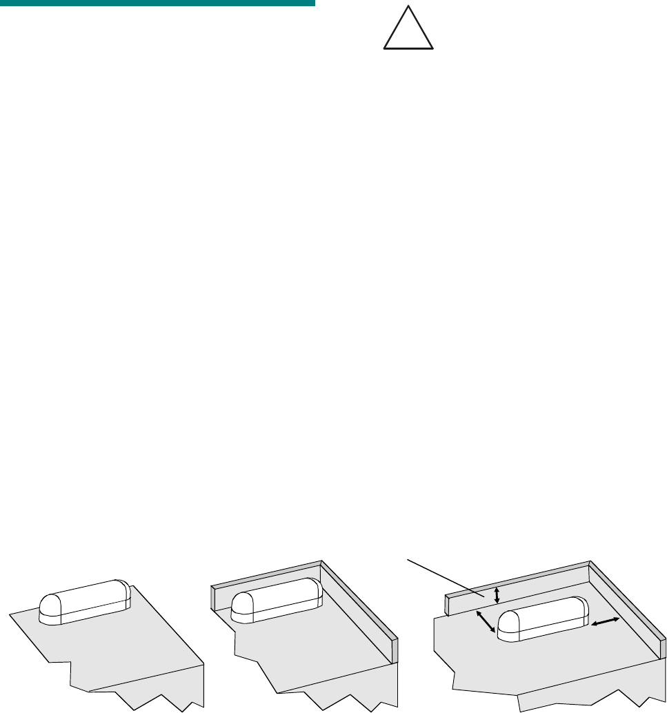
C•CURE Watch Installation and Service Guide A-3
Positioning Guidelines
How you position tags on assets can affect the
success of your asset management program. You
must ensure that the tag will not interfere with
asset use and that the asset does not interfere
with the tag’s signal. The following guidelines will
help you identify suitable locations for affixing tags:
• The tag must be affixed to a flat, solid surface.
A non-textured surface provides optimum
performance.
• Ensure that the tag is affixed to a non-
removable portion of the asset.
• Visibility of the tag is a matter of customer
preference. You might wish to apply tags in
highly visible locations or you might prefer to
select less obvious locations.
• Proximity to adjacent non-metallic surfaces
might discourage attempts to tamper with tag
application.
• Special care should be taken when mounting
asset tags on metal surfaces. Although the
asset tag is designed to be mounted on a flat
metal surface, performance might be degraded
if it is surrounded by metal.
CAUTION: Do not mount asset tags
in metal enclosures unless there is at
least .5cm (1in.) clearance between
the tag and any adjacent metal
surface and the metal surface does
not extend above the top of the tag.
• Examine the asset for opening covers and
other moving parts. Select a location where the
tag will not interfere with asset operation.
• Consider the asset’s interaction with other
assets, equipment and/or furniture. Allow
adequate room for laptop computers to connect
to a docking station.
• Select a site where the tag will not interfere
with asset storage. Check for clearance in
typical storage or transport situations such as
desk drawers, cabinets, or briefcases.
Once the tag is applied to the asset, the asset
must be defined in the system database. You will
need the Cross Reference Sheet that is shipped
with the tags. This sheet includes information (site
code and tag ID) that is required to define assets
using the correct data entry screen.
Note: You might want to make a copy of the
Cross Reference Sheet, filing one copy with your
system documentation and storing the other with
the asset tags.
All Surfaces Non-Metallic Surfaces Metallic Surfaces
No Higher than Tag
A
t Least
2.5cm (1in.) At Least
2.5cm (1in.)
!
A-4 8000-2803-01, Rev. 1/A Asset Tag Installation

C•CURE Watch Installation and Service Guide B-1
Appendix B
Managing RF Passage Antenna Performance
In This Chapter
Performance Overview ...............................................................................................B-2
Environmental Conditions Affecting Performance......................................................B-2
Cable/Line Interference........................................................................................B-2
Antenna Loading ..................................................................................................B-2
Antenna Interference ...........................................................................................B-2
Antenna Performance.................................................................................................B-3
One Antenna, .9m (3ft) ........................................................................................B-3
One Antenna, 1.8m (6ft) ......................................................................................B-3
Two Antennas, .9m (3ft).......................................................................................B-3
Two Antennas, 1.8m (6ft).....................................................................................B-3
Before You Begin .......................................................................................................B-4
Investigating Performance..........................................................................................B-4
Check for Obvious Sources of Interference.........................................................B-4
Check for Antenna Loading .................................................................................B-4
Investigate Antenna Interference .........................................................................B-4
Troubleshooting Tips ...........................................................................................B-5
Improving Performance .............................................................................................. B-5
Controlling Cable/Line Interference ..................................................................... B-5
Controlling Antenna Loading................................................................................B-5
Controlling Antenna Interference .........................................................................B-5
Troubleshooting Procedures ......................................................................................B-6
Using a Communications Receiver......................................................................B-6
Installing Cancellation Coils .................................................................................B-7

B-2 8000-2803-01, Rev. 1/A Managing RF Passage Antenna Performance
Performance Overview
The C•CURE Watch system uses RFID (radio
frequency identification) technology to gather
information for access control and asset tracking
applications. Under ideal conditions, RFID
technology provides a reliable method of
communicating information.
However, sometimes environmental conditions
interfere with passage reader performance.
Different conditions interfere with performance in
different ways—each requiring a different
performance management solution.
The first step in managing passage reader
performance is to evaluate potential installation
sites as part of a pre-installation site survey. The
survey ensures that C•CURE Watch passage
readers are installed in locations where
environmental conditions are not a problem—or at
least identifies potential problems before
installation.
In some cases, performance problems become
evident only after installation. This appendix
provides tools, strategies, and suggestions for
improving passage reader performance.
Troubleshooting RFID performance is not an exact
science. The tools and techniques provided in this
appendix provide a foundation for problem solving.
Experience with RFID technology also plays an
important role in this process; experience comes
only with practice.
Environmental Conditions
Affecting Performance
The following environmental conditions can
interfere with the ability of a C•CURE Watch
passage reader to detect a tag or card:
• Cable/line interference
• Antenna loading
• Antenna interference
Cable/Line Interference
Cable/line interference is conducted or induced into
the system through its cabling. Sources of
cable/line interference include:
• Switching power supplies such as ac/dc motors.
• Power spikes generated by input or output
devices connected to the RF controller.
• Door latch relay, power, or data cable runs
close to antenna wire cable runs.
Antenna Loading
Antenna loading occurs when a large metal object
in close proximity to a passage reader alters the
reader’s electromagnetic fields in a way that
interferes with performance.
Antenna Interference
Antenna interference occurs when radiated noise
disrupts the transmission process in a way that
prevents the tag or card signal from being detected
by the receiver.
There are several variables associated with
antenna interference. The closer the interference is
to C•CURE Watch operating frequencies
(134.2kHz and 123.2kHz), the greater its potential
for degrading system performance. Antenna
interference can be intermittent resulting in
passage antenna performance that is excellent at
some times and unacceptable at other times. In
addition, some sources of antenna interference are
directional so that their orientation in relation to the
passage reader can play a significant role in the
degree of interference.
Sources of antenna interference include:
• Equipment operating in the vicinity of a passage
reader. Any system that operates at a set
frequency is a potential source of interference.
Examples include but are not limited to:
computer or television monitors, automatic teller
machines, and elevators.
Generally, the closer the system or the more
powerful the interfering signal, the more likely it
is to cause a problem.
• Third-party RFID proximity readers operating in
the vicinity of the passage reader such as
Indala and HID.
C•CURE Watch system components can also
interfere with system performance.
Synchronizing all RF controllers at a site
prevents this type of interference.
• Multiple C•CURE Watch tags or cards
transmitting at the same time.
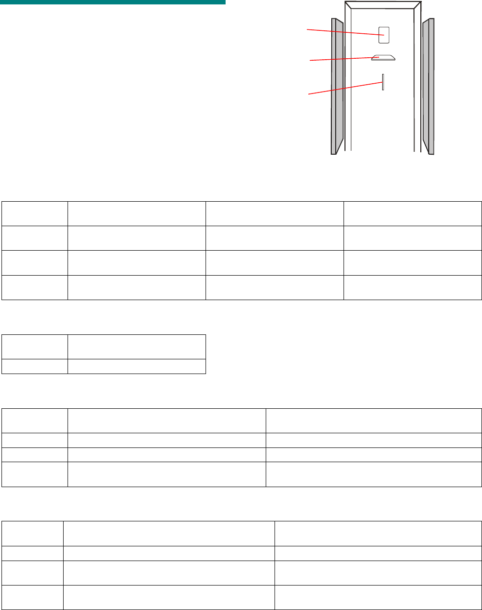
C•CURE Watch Installation and Service Guide B-3
Antenna Performance
The following antenna detection distances have
been verified by UL.
Note: “Top” means that detection occurred .6m
(1.5ft) from the top of the antenna. “Bottom” means
detection occurred .6m (1.5ft) from the floor.
Detection occurred between the top and bottom in
the indicated distances.
One Antenna, .9m (3ft)
Badge
Orientation
Model A (CW-ANT-PA) with
Wire Loop
Model A (CW-ANT-PA) without
Wire Loop
Model B (CW-ANT-PB) without
Wire Loop
Frontal Top and bottom .9m (3ft) Top .9m (3ft)
Bottom .76m (2.5ft)
Top .9m (3ft)
Bottom .76m (2.5ft)
Vertical Top and bottom .76m (2.5ft) Top .6m (2ft)
Bottom .76m (2.5ft)
Top .76m (2.5ft)
Bottom .6m (2ft)
Lateral Top .76m (2.5ft)
Bottom .6m (2ft)
Top .9m (3ft)
Bottom .76m (2.5ft)
Top .76m (2.5ft)
Bottom .9m (3ft)
One Antenna, 1.8m (6ft)
Badge
Orientation
Model A (CW-ANT-PA) with
Wire Loop
Frontal 1.8 m (6ft)
Two Antennas, .9m (3ft)
Badge
Orientation
One Model A (CW-ANT-PA) and
One Model B (CW-ANT-PB) with Wire Loop
One Model A (CW-ANT-PA) and
One Model B (CW-ANT-PB) without Wire Loop
Frontal Top and bottom .9m (3ft) Top and bottom .9m (3ft)
Vertical Top and bottom .76m (2.5ft) Top and bottom .9m (3ft)
Lateral Top .76m (2.5ft)
Bottom .6m (2ft)
Top and bottom .76m (2.5ft)
Two Antennas, 1.8m (6ft)
Badge
Orientation
Two Model A (CW-ANT-PA) with Wire Loop Two Model A (CW-ANT-PA) without Wire Loop
Frontal Top and bottom 1.8m (6ft) Top and bottom 1.8m (6ft)
Vertical Top and bottom 1.5m (5ft)
[.76m (2.5ft) from each side]
Top and bottom 1.8m (6ft)
Lateral Top 1.5m (5ft) [.76m (2.5ft) from each side]
Bottom .9m (3ft) [.6m (1.5ft) from each side]
Top 1.5m (5ft) [.76m (2.5ft) from each side]
Bottom .9m (3ft) [.6m (1.5ft) from each side]
Frontal
Lateral
Vertical

B-4 8000-2803-01, Rev. 1/A Managing RF Passage Antenna Performance
Before You Begin
When installation is complete, each passage
reader is tested with cards and/or tags that have
been defined in the host system. Performance is
acceptable if tags and cards are detected at a
distance of .9m (3ft) from the antennas and
anywhere between the antennas (no holes in
center of field).
If performance is not acceptable, the cause must
be identified. In many cases, poor performance is
caused by improper installation. Before beginning
what may be an unnecessary process, check the
following:
• Verify that all installation procedures have
been completed and that antennas are
properly tuned.
• Examine status LEDs while system is running,
the antenna LEDs associated with active
antennas should be flashing sequentially.
• Tighten all antenna wire connections on
antenna interface board—loose connections
can affect system performance.
• Verify that all RF controllers are properly
synchronized.
Investigating Performance
Although there are many ways to troubleshoot
passage reader performance, the following
suggestions are provided as a guideline. In some
cases experience and site-specific conditions may
dictate another approach.
The suggested procedures are sequenced so that
the most easily identifiable problems are eliminated
first. In most cases, the investigation process
should be completed in the sequence presented.
Some of these procedures require two people.
This section includes the following topics:
• Check for obvious sources of interference
• Check for antenna loading
• Investigate antenna interference
• Troubleshooting tips
Check for Obvious Sources of
Interference
In some cases, the source of interference can be
identified by a careful inspection of the passage
reader’s environment. Check for equipment such
as monitors, RFID readers (including unconnected
passage antennas), machines or motors, and
fluorescent lamps near passage antenna. Turn off
suspicious devices and test reader performance. If
performance improves when the device is turned
off, see Improve Performance on page B-5 for
suggestions about improving performance.
Check for Antenna Loading
When the possibility of cable/line interference has
been ruled out, follow these steps to check for
antenna loading:
1. Remove top caps from affected antennas.
2. Using a multimeter, measure antenna voltage.
3. If antenna is affected by antenna loading, the
source (a large metal object in the vicinity of the
antenna) must be determined and removed or
the passage reader must be moved.
Investigate Antenna
Interference
When the possibilities of cable/line interference
and antenna loading have been ruled out, follow
these steps to identify the source of antenna
interference:
1. Record rotary switch settings.
2. Set rotary switches to 9-1-0-9.
3. Turn RF controller power Off, then back On.
4. Verify individual antenna performance with a
badge or tag to identify affected antennas.
5. When source of antenna interference is
discovered, implement a solution presented in
Control Antenna Interference on
page B-5.
6. When testing is complete, turn RF controller
power Off, return rotary switches to original
configuration.
7. Turn RF controller power On.

C•CURE Watch Installation and Service Guide B-5
Troubleshooting Tips
The following suggestions may help troubleshoot
passage reader performance in unusual situations.
Existing Installations
If a passage reader that has been performing well
develops performance problems:
• Walk through area to see if there are evident
changes in the physical environment. Has
equipment been moved or new equipment
installed?
• Check with facilities and department personnel
regarding recent repairs. It is possible that
performance is affected by rerouted wiring or
other non-visible changes to existing
equipment.
Intermittent Interference
The following may help identify intermittent
interference:
• Test system performance at different times to
pinpoint the problem to a specific time period.
Check with facilities and department personnel
regarding equipment and processes that occur
during the periods when performance is an
issue.
• Check whether equipment in the vicinity
operates at different intensity at various times. If
so, it may be producing an unacceptable level
of interference only when operating at high
setting.
• Consider whether potential sources of
interference move in and out of the vicinity of
the passage reader. A fork lift may affect
performance only when it passes close to the
passage reader.
Multiple Sources of Interference
In some cases, a passage reader is affected by
more than one source of antenna interference. It
may be necessary to repeat the cycle of
investigation and control for antenna interference
until all sources are identified.
Improve Performance
There are several ways to control the effect of
interference on passage readers. Methods of
control vary depending on the source of
interference.
Control Cable/Line Interference
The following options may help control cable/line
interference:
• Install a UPS (uninterruptible power supply)
battery to filter RF controller power.
• Separate data and door latch relay cable runs
from antenna cable runs by at least 15cm (6in.).
• Call tech support for assistance in
troubleshooting interference related to inputs
and/or outputs.
Control Antenna Loading
Avoidance is the only way to control antenna
loading; either the metal object or the affected
passage reader must be moved.
Control Antenna Interference
There are several ways to control antenna
interference:
• Move reader or source of interference
• Install cancellation coils
• Consult your technical support representative.
Relocate the reader or the source of interference
so that system performance is no longer affected.
This is the most permanent solution.
In some cases, modifying the orientation of the
source of interference can improve system
performance—try changing the vertical/horizontal
orientation or rotating it. Experiment with several
positions to determine impact on passage reader
performance.
Cancellation coils are used to control localized,
well-defined sources of antenna interference. The
coils are assembled and connected using standard
18AWG, plenum rated wire. A cancellation coil is
connected to an affected antenna, then attached to
the source of antenna interference.
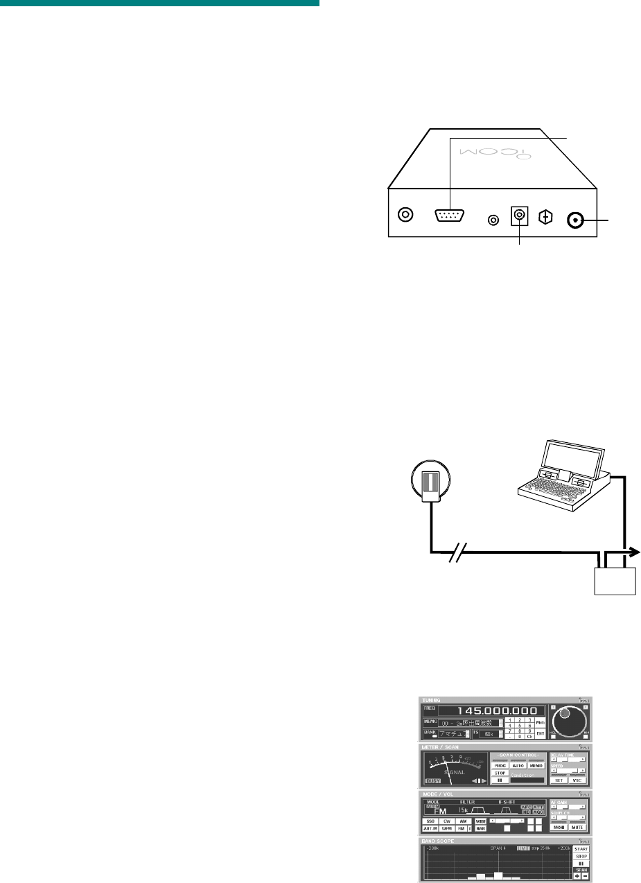
B-6 8000-2803-01, Rev. 1/A Managing RF Passage Antenna Performance
Troubleshooting Procedures
One or more of the following procedures may be
required to manage passage reader performance:
• Isolate an antenna.
• Use a communications receiver
• Install cancellation coils
Isolate an Antenna
1. Set rotary switches as specified below.
Antenna Rotary Switch Settings
19-7-1-9
29-7-2-9
39-7-4-9
49-7-8-9
2. Turn RF Controller power off, then on.
Use a Communications Receiver
A communications receiver is used to search for a
source of antenna interference after affected
antennas have been identified and all obvious
sources of interference have been eliminated.
Required Equipment
This procedure requires two people and the
following equipment:
• Ground isolated or battery powered
oscilloscope (200MHz Tektronix THS730A and
10X probes recommended).
• 4 jumpers with alligator clips on both ends.
• Digital multimeter.
• 100 feet of 50 ohm coax cable with BNC
connector on one end and alligator clips on
other end.
• C•CURE Watch proximity reader (VS-ANT-S2).
• ICOM IC-PCR1000 communications receiver
and serial communications cable.
• Laptop computer with IC-PCR1000 software
(revision 1.3 or later) installed. A fully charged
internal battery is required.
Set Up the Receiver
1. Turn Off power to RF controller and PC.
Note: NEVER operate PC using external ac
power. This will create a new source of
interference that is detected by receiver.
2. Connect serial communication and power to
ICOM receiver.
Use serial communication cable to connect
ICOM receiver to PC.
3. Connect coaxial cable to communication
receiver and C•CURE Watch proximity reader.
Connect BNC connector on coaxial cable to
BNC connector on communication receiver.
Connect alligator clips at end of coaxial cable to
the antenna connectors of the C•CURE Watch
proximity reader. DO NOT APPLY POWER TO
THIS ANTENNA.
4. Turn on communication receiver and PC.
5. Start IC-PCR1000 software and change View
settings to Component Screen.
Serial
Communication
BNC
Connector
Power
PC
C•CURE Trac
Proximity
Reader
To ac
Communication
Receiver
ICOM
C•CURE Watch Installation and Service Guide B-7
6. Set IC-PCR1000 parameters.
Tuning Components:
Frequency to 130kHz (0.130.000).
Tuning Step (TS) to 100 Hz.
Meter/Scan Components:
Delay Time to minimum.
Speed to maximum.
Mode/Vol Components:
Modulation to AM.
Narrow (NAR) filter to 3kHz.
Turn on Automatic Gain Control (AGC).
Audio Frequency (AF) gain to desired level
(muting this feature is recommended to help
determine strength of RF field being
monitored).
Attenuation (ATT) can be activated as
needed if signal strength saturates receiver.
Band Scope Components:
Press Start and set Span to 1 by pressing
the minus (–) sign. This sets span to ±25kHz.
When all parameters are set, you are ready to
search for sources of interference.
Searching for Source of Interference
Use RF antenna and feedback from the IC-
PCR1000 software to search for source of
interference. Two people are required for this
process. One person to move C•CURE Watch
proximity reader and another to monitor and relay
information from the PC.
The reader picks up RF signals in the environment.
The strength of these signals is monitored with IC-
PCR1000 software.
The process is similar to the game of “Hot and
Cold.” Hold the C•CURE Watch proximity reader
vertically and stand next to the antenna most
affected by the source of interference. Keeping the
reader in a vertical position, note scope readings
on PC as reader faces different directions.
The scope monitors signal strength and frequency.
Readings are more significant as noise level
increases (higher bars) and frequency approaches
target frequency (center of scope).
Move in the direction being faced when most
significant scope readings were noted. Slowly work
through the area using this technique, always
moving in the direction indicated by more
significant readings.
Place the reader near potential sources of
interference such as: electronic equipment, alarm
modules, and power supplies. Include walls and
columns in the test since interference sources may
be hidden.
At some point, high noise levels close to the target
frequency will pinpoint the source of interference.
Confirm using one of the following procedures:
• Hold the reader close to the source while
rotating 90 degrees (so it is parallel with the
floor). If noise levels drop significantly, this is a
source of antenna interference.
• If the suspected source is an electrical device,
turn it on and off. If noise levels disappear or
decrease significantly when the device is off, it
is a source of antenna interference.
Install Cancellation Coils
The following procedure describes how to control
antenna interference by installing cancellation coils
on passage antennas.
The following topics are covered:
• Before you begin
• Required equipment
• Planning wiring configuration
• Making cancellation coils
• Making antenna coupling loop
• Installing antenna coupling loop
• Installing coils
• Finishing the installation
Before You Begin
Affected antennas and their associated sources of
antenna interference must be identified before
cancellation coils can be installed.
The following guidelines apply:
• Only localized, well-defined sources of antenna
interference can be canceled with coils.
• The procedure is practical for canceling up to
three different sources of interference per
antenna. The cancellation process is more
difficult when multiple sources of interference or
multiple antennas are involved.
• The source of interference must remain
absolutely fixed in position once the coil is
B-8 8000-2803-01, Rev. 1/A Managing RF Passage Antenna Performance
installed. Even small movements can
compromise passage reader performance.
Required Equipment
The following equipment is required to create and
install noise cancellation coils:
• Tools for removing and assembling the antenna
cover
• 2-conductor, 18AWG, plenum cable
• A cylindrical object approximately 8cm (3in.) in
diameter (such as a coffee mug)
• Electrical or transparent tape
• Packing or duct tape
• Wire nuts
• Ground isolated or battery powered oscilloscope
Plan Wiring Configuration
The noise cancellation process connects coils to
affected antennas. The way you connect coils
depends on the number of interference sources
and the number of antennas. Use the following
guidelines to plan the wiring configuration:
• Establish a connection between the source of
interference and each antenna it affects.
• Provide a separate coil for each affected
antenna.
• Attach only one antenna coupling loop to an
antenna. When more than one source of
interference affects an antenna, the coils must
be connected in series.
The following examples illustrate these guidelines:
• One source of interference and two antennas —
if both antennas are affected, two coils are
needed.
• Two sources of interference and two antennas
— if each source affects only one antenna, two
coils are needed.
• Two sources of interference and two antennas
— if both sources affect both antennas, four
coils are needed.
Make Cancellation Coils
A coil is made with a single strand of insulated
wire.
1. Cut a piece of 2-conductor wire approximately
7.6m (25ft) long and remove outer sheath to
separate wires.
2. Take one of the wires and wind it into a circular
coil with a diameter of approximately 8cm (3in.).
Each coil should contain 25 to 30 turns. Leave
approximately 8cm (3in.) of wire at each end of
coil.
Dimensions of coil are not critical. For
convenience, use a coffee mug or roll of duct
tape as a base for winding.
Note: If needed, use second wire to make
another coil.
3. Use electrical or transparent tape to secure coil
in four spots to keep it from unwinding.
4. Strip about 2cm (.75 in.) of insulation from both
ends of coil.
Source o
f
Interference
Source o
f
Interference
Source o
f
Interference
Source o
f
Interference
Source o
f
Interference
C•CURE Watch Installation and Service Guide B-9
5. Make one coil for each source of
interference/antenna combination.
Set completed coils aside while you prepare
antenna coupling loops and antenna wires.
Make Antenna Coupling Loop
The antenna coupling loop is made using standard
2-conductor wire.
1. Begin with a piece of 2-conductor wire long
enough to reach from antenna to source of
interference.
Remember to measure installation path (not line
of sight) from antenna to source of interference.
Allow additional wire to create antenna coupling
loop and for positioning coil.
You may want to make/attach antenna coupling
loop and run wire to source of interference
before cutting it.
2. Remove 46cm (18in.) of outer sheath from one
end of wire, so that wires can be separated.
3. Strip 4cm (1.5in.) of insulation from end of each
wire.
4. Form a loop by splicing the two wires.
Antenna coupling loop is now ready to install.
Remaining wire is referred to as antenna wire in
the following steps.
Prepare Antenna for Cancellation
The noise cancellation process must be performed
on one antenna at a time. Follow these steps to
prepare the antenna.
1. Isolate antenna being cancelled. For more
information see Isolate an Antenna on page B-
6.
2. Remove antenna end caps.
3. Remove antenna cover.
Install Antenna Coupling Loop
Installing the antenna coupling loop is a critical
step in the noise reduction process. It is important
to follow the recommended guidelines for
positioning the loop.
Tape 8cm
(3in.)
25 to 30 Turns
in Each Coil
4cm
(1.5in.)
46cm
(18in.)
Splice
Antenna Wire
Antenna
Coupling
Loop
A
ntenna
Cover
Top End Cap
Bottom End Cap
B-10 8000-2803-01, Rev. 1/A Managing RF Passage Antenna Performance
The antenna coupling loop must be mounted just
above the third cutout.
1. Determine how you will install antenna wire
between antenna and source of interference.
Site requirements for safety and appearance
will influence how wire is installed. Antenna wire
can exit antenna from top or bottom to meet
installation requirements.
2. Attach antenna coupling loop to antenna. It is
important to accurately position bottom of loop.
Use packing or duct tape to attach loop to either
side of antenna so that bottom of loop is .6cm
(.25in.) above the top of third cutout and so that
it extends the full distance between vertical
antenna channels (from left to right).
Once bottom of loop is secure, extend rest of
loop vertically, along antenna channels and
secure. Positioning of upper portion of antenna
coupling loop is not critical.
Note: Splice can be positioned at top or bottom
of antenna to accommodate antenna wire
exiting at top or bottom of antenna. Be sure
bottom of loop is positioned accurately.
When installed, antenna coupling loop should
look like this:
3. Run antenna wire to top or bottom of antenna.
Route wire to back edge so that end caps can
be installed when installation is complete.
4. Run antenna wire along selected installation
route to source of interference.
5. Prepare wire for connection to coil.
If cutting antenna wire at this point, leave a
generous allowance for positioning coil. Strip
about 4cm (1.5in.) of outer sheath. Strip 2cm
(.75in.) of insulation from each wire.
Install Coils
For effective cancellation, coils must be positioned
as close as possible to source of interference. As a
general rule, the stronger the interference, the
closer the coil will need to be positioned to it.
Consider the following guidelines when positioning
coils for noise cancellation:
• Position coils to achieve the lowest possible
noise level within the typical range.
• Test antenna performance in addition to
adjusting noise levels. Noise levels affect
system performance to different degrees based
on the source of interference. A noise level of
1.3V may compromise system performance
mildly or significantly, depending on its source.
Based on conditions at the site, you may need to
connect one coil or multiple coils to the antenna
wire. If there are several affected antennas, the
wiring configuration may include both types of
connections.
When multiple sources of interference and/or
multiple antennas require cancellation coils, the
positioning and fine tuning of coils is an iterative
Third Cutout from Top
Antenna Coupling
Loop
.6cm (.25in.) from
Top of Cutout
Area of Critical
Positioning
C•CURE Watch Installation and Service Guide B-11
process. Once you have installed and fine tuned all
coils, recheck noise cancellation for each coil and
reposition it if necessary. Repeat this process until
you are satisfied with system performance.
Connecting One Coil
Follow these steps to connect one coil to an
antenna.
1. Verify that source of interference is in its
permanent operating position.
It is important to avoid moving source of
interference after installation is complete.
2. Connect coil to antenna wire.
Twist wire at one end of coil with either antenna
wire and secure it with a wire nut. Repeat with
remaining coil and antenna wires.
3. Determine most effective placement for coil.
Monitor cancellation effects as you experiment
with potential mounting locations. Start by
monitoring effects of gross position changes,
gradually making smaller and smaller changes
between test locations.
Note: If possible when multiple sources of
interference are involved, turn off all except one
being tested.
4. Attach coil to source of interference using
packing or duct tape.
Use only enough tape to hold coil in position
during installation process. You may need to
reposition coil later.
5. Fine tune noise cancellation.
Small changes in coil shape affect noise
cancellation results. Fine tune by making small
changes to shape of coil. Monitor effects of
these changes until cancellation is optimized.
6. Install all coils before proceeding to section,
Finish the Installation on page B-12 .
Connect Multiple Coils
When more than one source of interference affects
an antenna, you must connect coils to the antenna
wire in series. For this configuration, use separate
pieces of 2-conductor wire to connect one coil to
another. In the following steps this wire is referred
to as a connecting wire.
1. Verify that source of interference is in its
permanent operating position.
It is important to avoid moving sources of
interference after installation is complete.
2. Connect first coil to antenna wire and
connecting wire.
Twist one coil wire with white antenna wire and
secure with a wire nut. Twist other coil wire with
white wire of connecting wire and secure with a
wire nut.
Twist black wire of the antenna wire with black
wire of the connecting wire and secure with a
wire nut.
Set coil as close as possible to source of
interference.
3. Run connecting wire to second source of
interference and cut, leaving a generous
allowance for positioning coil.
Strip about 4cm (1.5in.) of outer sheath from cut
end. Strip 2cm (.75in.) at end of each wire.
4. If only two coils are required in this series,
proceed to Step 6.
Or…
If three coils are required, connect second coil
to connecting wire from first coil and another
connecting wire.
Twist one coil wire from second coil with white
connecting wire from first coil and secure with a
wire nut. Twist other coil wire with white wire of
another connecting wire and secure with a wire
nut.
Coil
Antenna Wire
Coil
Connecting Wire Antenna Wire
Second
Coil
Second
Connecting Wire
Antenna Wire
First
Coil
First
Connecting Wire
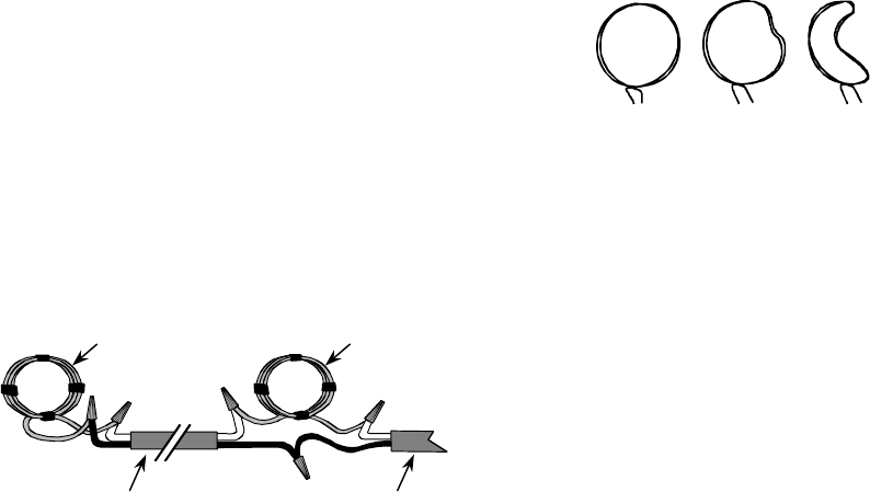
B-12 8000-2803-01, Rev. 1/A Managing RF Passage Antenna Performance
Twist black wire of connecting wire from first
coil with black wire of new connecting wire and
secure with a wire nut.
Set coil as close as possible to source of
interference.
5. Run connecting wire to third source of
interference and cut, leaving a generous
allowance for positioning coil.
Strip about 4cm (1.5in.) of outer sheath from cut
end. Strip 2cm (.75in.) at end of each wire.
6. Connect last coil to connecting wire.
Twist wire at one end of coil with one of
connecting wires and secure with a wire nut.
Repeat with remaining coil and connecting wire.
Set coil as close as possible to source of
interference.
7. Determine most effective placement for first
coil.
Be sure coils are located as close as possible to
sources of interference.
Monitor cancellation effects as you experiment
with potential mounting locations. Start by
monitoring effects of gross position changes,
gradually making smaller and smaller changes
between test locations.
Note: If possible when multiple sources of
interference are involved, turn off all sources
except one being tested.
8. Attach coil to source of interference using
packing or duct tape.
Use only enough tape to hold coil in position
during installation process. You may need to
reposition coil later.
9. Fine tune noise cancellation for first coil.
Small changes in coil shape affect noise
cancellation results. Fine tune by making small
changes to shape of coil. Monitor effects of
these changes until cancellation is optimized.
10. Repeat steps 7–9 for second and (if needed)
third coils.
11. Install all coils before proceeding to next section
Finish the Installation.
Finish the Installation
When all required coils have been connected, you
are ready to finish the installation.
1. Recheck noise cancellation for each coil.
When multiple sources of interference must be
canceled, the placement of subsequent coils
can affect noise cancellation results for coils
that are already installed.
Use oscilloscope to monitor noise levels for
each coil. Readjust positioning and/or fine
tuning as needed.
Repeat this step until you are satisfied with
noise cancellation for all coils.
Note: Remember to turn Off RF controller and
set DIP switch for proper antenna when fine
tuning results for multiple antennas.
2. Use packing or duct tape to permanently attach
coils.
Do not move sources of interference once coils
have been installed. Even small changes in
position can have a significant impact on noise
cancellation results.
3. Reconfigure antennas for normal operation.
Using your notes about reader connections and
dip switch settings, reconnect antennas to the
reader. If necessary, adjust the reader
operating mode by setting the dip switches.
4. Verify antenna operation.
Using a transponder, verify that all antennas are
operating properly.
5. Replace antenna cover and end caps.
Last Coil
Connecting
Wire
Connecting o
r
Antenna Wire
First or Second Coil