Tyco Safety Sensormatic DEACMER Anti-Theft Device User Manual ZBSMPRO
Tyco Safety Products/Sensormatic Anti-Theft Device ZBSMPRO
users manual
Company Confidential
SCANMAX PRO INSTALLATION AND SETUP GUIDE (8200-0054-01, REV. 02)
1 of 5
ZBSMPRO
ZBSMPROZBSMPRO
ZBSMPRO
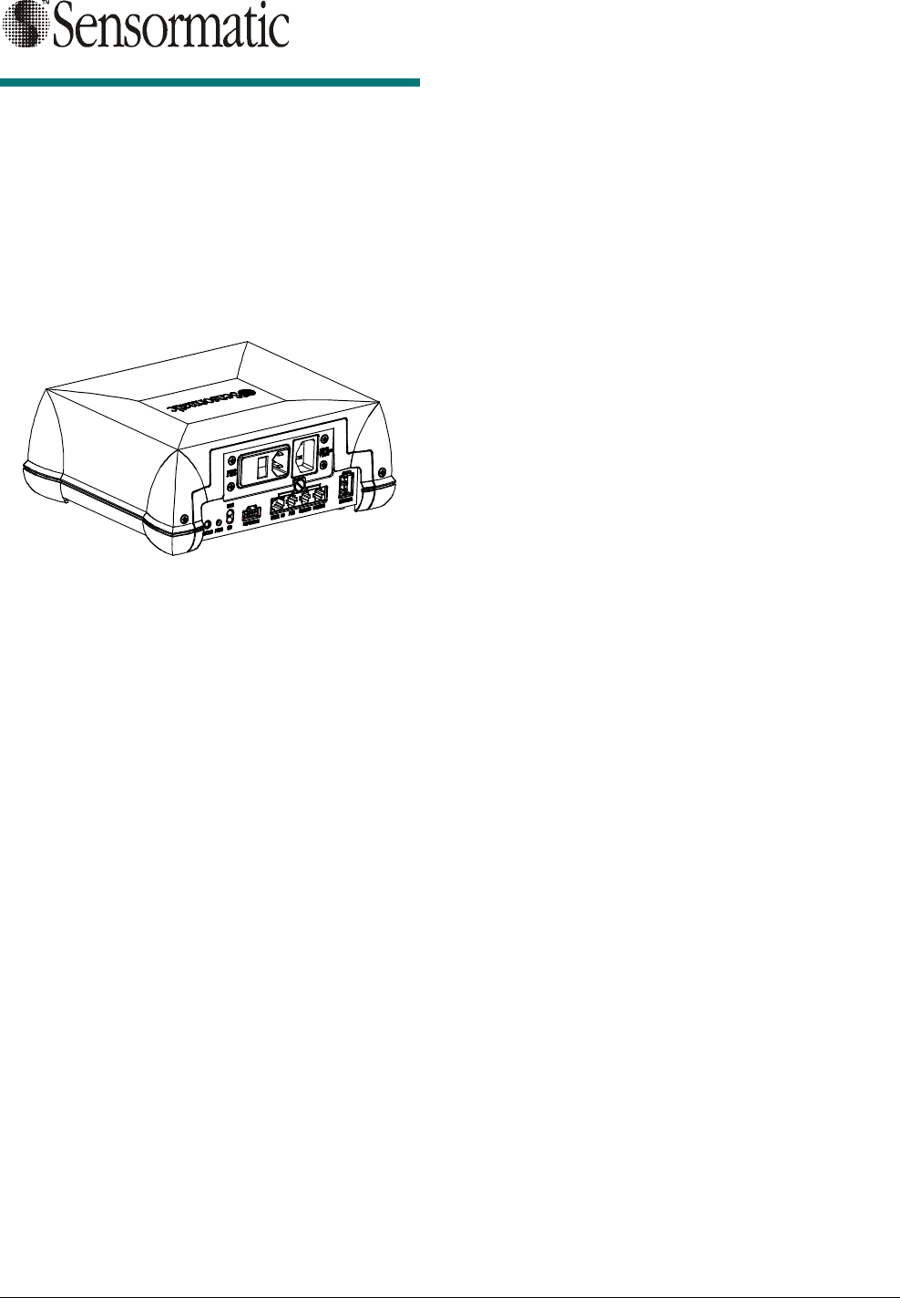
ScanMax™ Pro
ScanMax™ Pro ScanMax™ Pro
ScanMax™ Pro
Controller
ControllerController
Controller
Installation and Setup Guide
Installation and Setup GuideInstallation and Setup Guide
Installation and Setup Guide
ScanMax Antennas Used with
ScanMax Antennas Used with ScanMax Antennas Used with
ScanMax Antennas Used with
this Controller
this Controllerthis Controller
this Controller
! PowerPad (ZBSMPPP)
! Slim Pad (ZBSMPSP)
! CompactPad Tabletop Version (ZBSMPCP)
! CompactPad Flush Mount Version
(ZBSMPCP-F)
! Low Profile Pad (ZBSMPLP)
! Integrated Pad (ZBSMPIP)
© Sensormatic 2002
Equipment Required
Equipment RequiredEquipment Required
Equipment Required
• Controller
• Laptop with minimum Windows 98 SE
• Standard CE RS232 Ultra•Max programming
cable
• Hard Tag
• Four DR LE labels minimum
Installation
InstallationInstallation
Installation
The controller can be mounted three ways:
! On the countertop
! To the underside of the countertop
! To the sidewall of the counter.
Warning! If mounting the controller to the sidewall
of a counter, its cable connectors cannot face up.
The controller can be mounted, out-of-the-box, to
the countertop. If mounted to the underside of the
countertop or to the sidewall of the counter, a
mounting bracket is required. This bracket contains
key slots for easy mounting.
Detailed mounting instructions are supplied with
the bracket.
Company Confidential
SCANMAX PRO INSTALLATION AND SETUP GUIDE (8200-0054-01, REV. 02)
2 of 5
Setup
SetupSetup
Setup
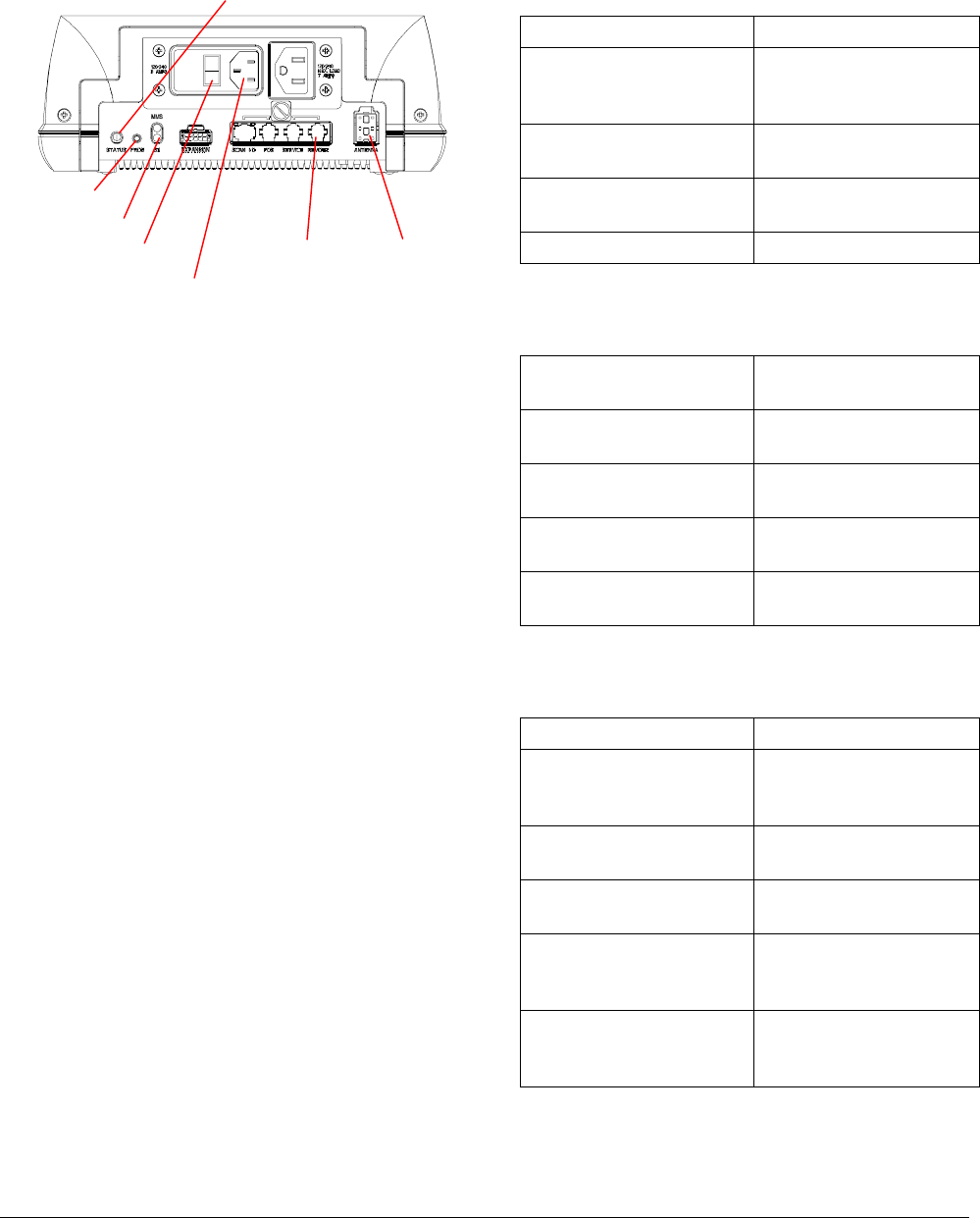
1. If supplied, plug the remote cable into the
“remote” controller port.
2. Plug in the antenna cable.
3. Plug the AC cord into the input male jack.
4. Turn on the AC power. The rocker switch
should be ‘green’ and the status indicator may
blink orange until the controller auto-
synchronizes. When synchronizing is
complete, the status indicator should be solid
green. Auto synchronization can take up to ten
seconds.
Note: If the status indicator is blinking green,
then either the deactivation or transmit function
is disabled. If the indicator is alternating
red/yellow or is solid red, then there is no high
voltage available for deactivation. In either
case, contact ADT for advice. The complete list
of status indications is shown opposite.
Controller Status Indicators
Controller Status IndicatorsController Status Indicators
Controller Status Indicators
Status Indicator on Controller (Note: Red color
may appear orange.)
Solid Green Unit ready.
Blinking Green Transmit disabled by
key switch or
configurator.
Blinking Yellow Controller is in auto-
sync.
Alternating Red/Yellow The high voltage circuit
is not working.
Solid Red +25V or sync fault.
Mode Indicator on Controller (Use the PROG
Button to cycle through the selections below.)
Bottom LED On The controller is set for
use with an SR label.
Bottom LED Off The controller is set for
use with a DR label.
Top LED On The controller is set for
Mag-Safe operation.
Top LED Off The controller is set for
routine operation.
Both LEDs Blink Antenna EEPROM
fault.
Status Indicators on
Remote Alarm Module (if used)
Green On, Red Off Unit ready.
Blinking Green Transmit disabled by
key switch or
configurator.
Green On, Yellow
Blinks Controller is in auto-
sync.
Green On, Red
Flashing Every 250 ms The high voltage circuit
is not working.
One Beep The controller
attempted to deactivate
a label.
Continuous beep until a
hard tag is removed
from the field.
The controller is in HT
test mode.
Remote
Port Antenna
Port
AC Power Cord
AC Power Switch
Status Indicator
Program Button
Mode Indicator
Company Confidential
SCANMAX PRO INSTALLATION AND SETUP GUIDE (8200-0054-01, REV. 02)
3 of 5
Advanced Setup and
Advanced Setup and Advanced Setup and
Advanced Setup and
Adapter Configuration
Adapter ConfigurationAdapter Configuration
Adapter Configuration
1. Plug in the programming cable into the service
port of the controller.
2. Start the ScanMax Pro configurator by clicking
on the icon.
3. Verify settings as follows for your antenna
type. Do not change settings at this time.
Default Settings
Antenna Tx Power Threshold
Low Profile
Pad Med 8 (+1)"
20 (+2.5) cm
PowerPad Med 7 (+1.5)”
17.5 (+3.75) cm
SlimPad Med 6 (+1.5)"
15 (+3.75) cm
ScanMax IP Med 6 (+1.5)"
15 (+3.75) cm
CompactPad Med 6 (+1)"
15 (+2.5) cm
4. Use the threshold setting to adjust the
detection height for the checkout environment.
Use the detection compensation slide bar to
compensate for special mounting such as
metal countertops.
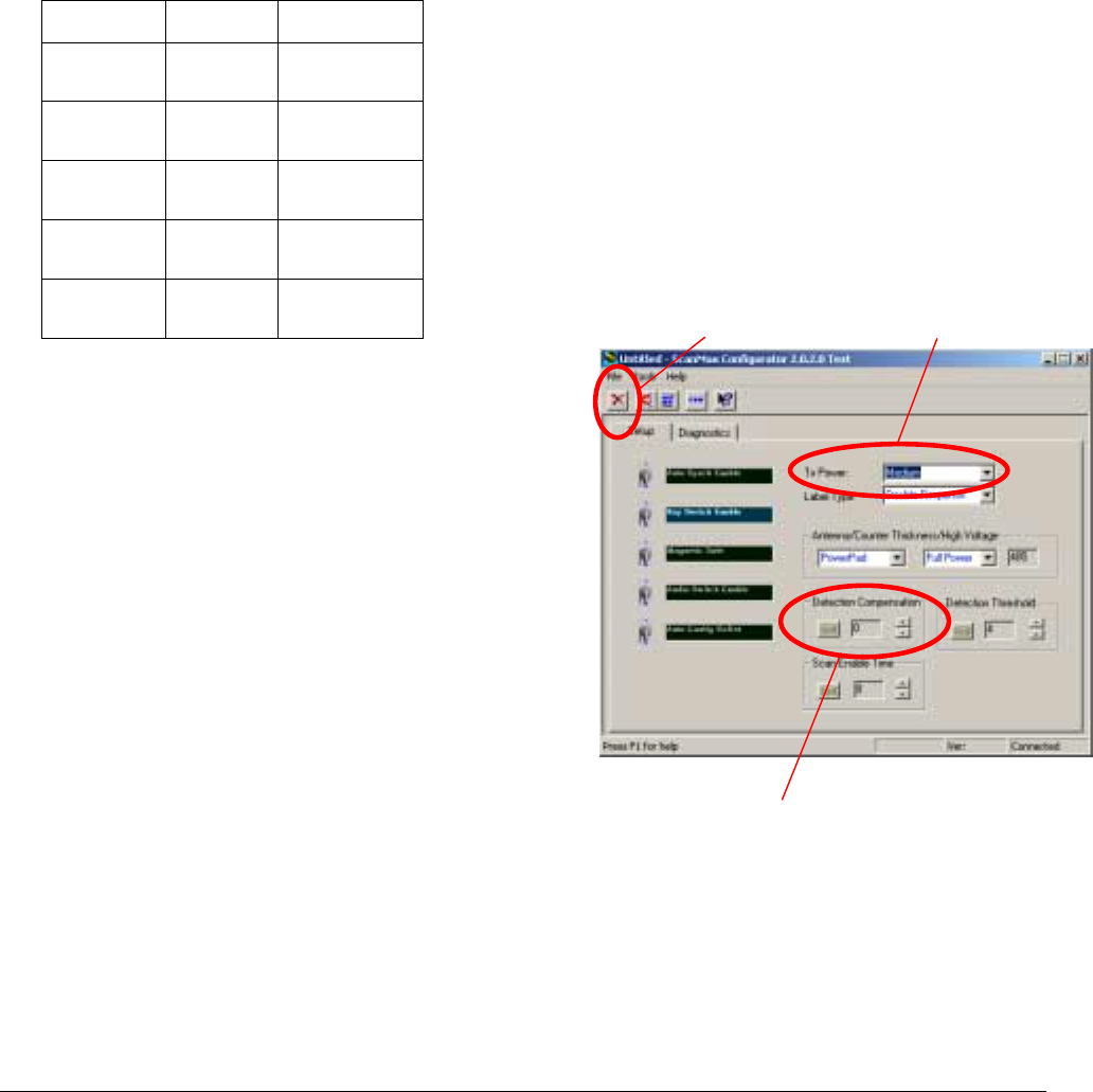
5. Using the EXIT button on the configurator, exit
the configurator.
If false deactivating occurs…
If false deactivating occurs… If false deactivating occurs…
If false deactivating occurs…
If false deactivating occurs, the configuration
default values need to be modified as follows:
a. Plug in the programming cable into the Service
port of the controller.
b. Start the ScanMax Pro configurator by clicking
on the icon.
c. Click on the RESYNC button. If false
deactivation discontinues, go back to step 4;
otherwise, continue.
d. Ensuring no label/tag is close to the antenna,
reduce Tx POWER one level at a time until the
system does not false deactivate (firing without
a label/tag present). Write this level down.
e. Set the Tx POWER level one step higher.
Note: Maximum detection and deactivation
height may be reduced compared with that
listed in the table due to ambient noise and
mounting locations. Note the new heights.
f. If these steps fail to stop false deactivation,
contact Service Planning.
Exit Button
Detection Compensation
Tx Power

Company Confidential
SCANMAX PRO INSTALLATION AND SETUP GUIDE (8200-0054-01, REV. 02)
4 of 5
Specifications
SpecificationsSpecifications
Specifications
Electrical
ElectricalElectrical
Electrical
Primary input.......................... 100-120/200-240 Vac
50-60 Hz ±5%
1.4 Arms maximum
Environmental
EnvironmentalEnvironmental
Environmental
Operating temperature........... 0 to 40°C
(32°–104°F)
Non-operating temperature.... –40° to 70°C
(–40° to 158°F)
Relative humidity.................... 0 to 90% non-condensing
Mechanical
MechanicalMechanical
Mechanical
Height..................................... 10 CM (3.9 in.)
Width...................................... 26.3 cm (10.4 in.)
Depth ..................................... 22.1 cm (8.7 in.)
Weight.................................... 2.5 kg (5.5 lbs.)
Declarations
DeclarationsDeclarations
Declarations
Regulatory Complia
Regulatory CompliaRegulatory Complia
Regulatory Compliance
ncence
nce
Emissions...............................47 CFR, Part 15
ENS 300 330
EN 301489
EN61000-3-2
EN61000-3-3
RSS 210
Safety .....................................UL60950
CSA C22.2 No 60 950
EN 60 950
FCC COMPLIANCE: This equipment complies with Part 15
of the FCC rules for intentional radiators and Class A digital
devices when installed and used in accordance with the
instruction manual. Following these rules provides reasonable
protection against harmful interference from equipment
operated in a commercial area. This equipment should not be
installed in a residential area as it can radiate radio frequency
energy that could interfere with radio communications, a
situation the user would have to fix at their own expense.
EQUIPMENT MODIFICATION CAUTION: Equipment
changes or modifications not expressly approved by
Sensormatic Electronics Corporation, the party responsible for
FCC compliance, could void the user's authority to operate the
equipment and could create a hazardous condition.
Other Declarations
Other DeclarationsOther Declarations
Other Declarations
WARRANTY DISCLAIMER: Sensormatic Electronics
Corporation makes no representation or warranty with respect
to the contents hereof and specifically disclaims any implied
warranties of merchantability or fitness for any particular
purpose. Further, Sensormatic Electronics Corporation
reserves the right to revise this publication and make changes
from time to time in the content hereof without obligation of
Sensormatic Electronics Corporation to notify any person of
such revision or changes.
LIMITED RIGHTS NOTICE: For units of the Department
of Defense, all documentation and manuals were developed at
private expense and no part of it was developed using
Government Funds. The restrictions governing the use and
disclosure of technical data marked with this legend are set
forth in the definition of “limited rights” in paragraph (a) (15)
of the clause of DFARS 252.227.7013. Unpublished - rights
reserved under the Copyright Laws of the United States.
TRADEMARK NOTICE: ScanMax, Sensormatic, and the
Sensormatic logo are trademarks or registered trademarks of
Sensormatic Electronics Corporation. Other product names
mentioned herein may be trademarks or registered trademarks
of other companies.
No part of this guide may be reproduced in any form without
written permission from Sensormatic Electronics Corporation.
MDR 3/02

Company Confidential
SCANMAX PRO INSTALLATION AND SETUP GUIDE (8200-0054-01, REV. 02)
5 of 5