Tyco Safety Sensormatic DEACSTP Accessory, label deactivator User Manual 2599 01a
Tyco Safety Products/Sensormatic Accessory, label deactivator 2599 01a
UserManual.wiki
>
Tyco Safety Sensormatic
>
DEACSTP User Manual
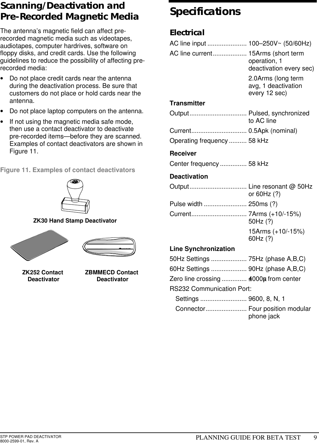
Planning Guide
Navigation menu
Upload a User Manual
Namespaces
Wiki Guide
HTML
PDF
Info
Views
User Manual
Discussion / Help
Navigation