Tyco Safety Sensormatic DEACSTP Accessory, label deactivator User Manual 2599 01a
Tyco Safety Products/Sensormatic Accessory, label deactivator 2599 01a
Planning Guide
Planning Guide for Beta Test
8000-2599-01, Rev. A (10 pages) DEACTIVATION PRODUCTS 1
Scan-Thru™ Platform
Proximity Deactivator
ZBSTP-PK-1 Power Pack
ZBSTP-PP Power Pad Antenna
Contents
About this Guide.................................................... 1
About the Deactivator............................................ 2
IMPORTANT SAFEGUARDS ............................... 5
Pre-Install Preparation .......................................... 5
Specifications ........................................................ 9
Declarations ........................................................ 10
About this Guide
This guide explains installation configurations,
requirements, and specifications for the Scan-Thru
Platform (STP) proximity deactivator. Other related
documents are:
• Installation Guide, 8000-2599-02
• Setup and Service Guide, 8000-2599-11
Note: The exact placement of the deactivator will
depend on customer requirements. See your
Sensormatic representative for this information.
If you need assistance...
Call Sensormatic Customer Support at:
1-800-543-9740
Scan-Thru, Sensormatic, and the Sensormatic logo are
registered trademarks of Sensormatic Electronics Corporation.
Other product names (if any) mentioned herein may be
trademarks or registered trademarks of other companies.
No part of this guide may be reproduced in any form without
written permission from Sensormatic Electronics Corporation.
© Copyright 1998. All rights reserved.
MDR 12/98
2PLANNING GUIDE FOR BETA TEST
STP POWER PAD DEACTIVATOR
8000-2599-01, Rev. A
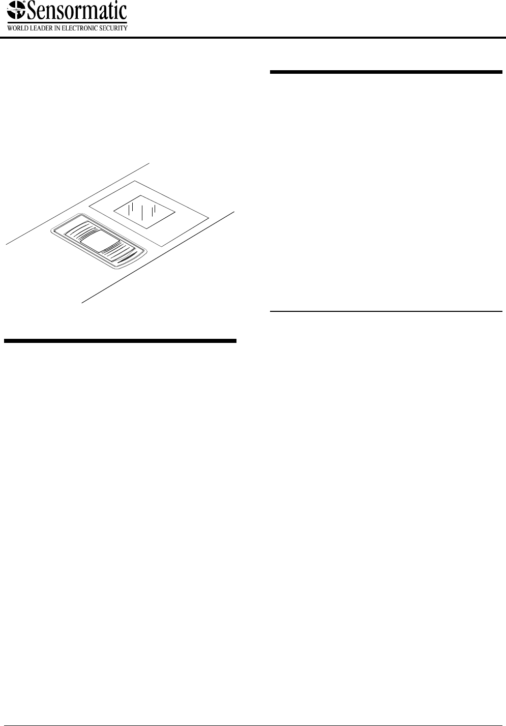
About the Deactivator
The STP Deactivator (Figure 1) reliably deactivates
Sensormatic UltraStrip II and Ultrastrip III security
labels during the bar-code scanning process when:
• Installed immediately downstream from
the bar-code scanner.
• UltraStrip II and III security labels are properly
applied to items
• Labeled items are moved properly across the
antenna on their way to the bag well or bagging
station.
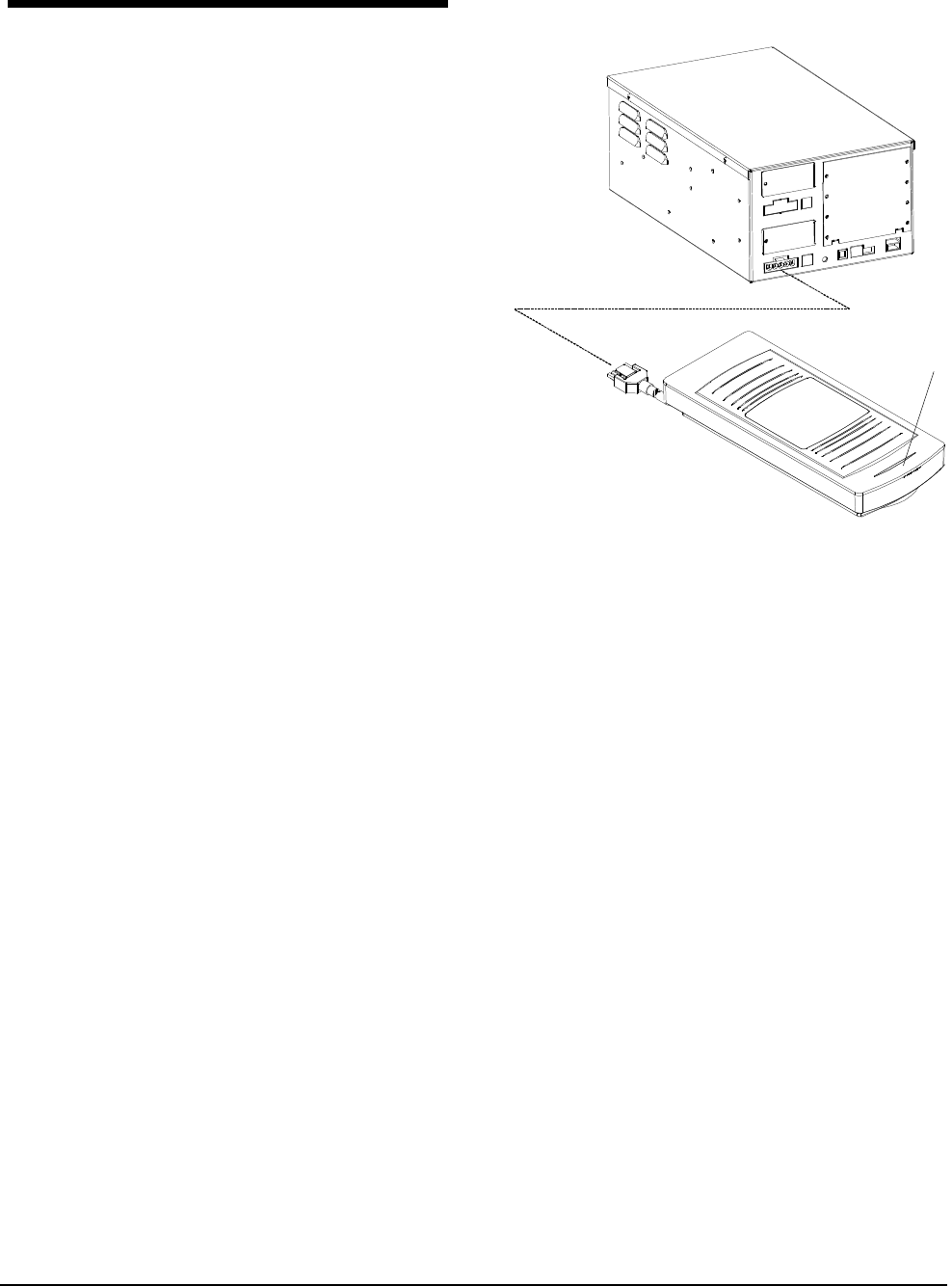
The deactivator consists of a hidden power pack, a
countertop antenna with interconnect cable.
• ZBSTP-PK-1 power pack controls antenna
operation. At the rear of the pack is an ac
receptacle for an 3m (10') power cord. In front
is a power on LED; connections for the
interconnect cable, an optional remote LED
board or remote indicator module (see options),
a laptop configurator, POS integration, and
RS485 port; and DIP switches (SW1) for phase
and sensitivity adjustments. A bracket enables
the pack to attach to the underside of a
countertop.
• ZBSTP-PP Power Pad antenna generates a
15cm (6") (???-to be verified) high by 20cm (8")
wide magnetic field above its surface to detect
and deactivate UltraStrip II security labels.
The antenna can be placed on the countertop, or
using various brackets, mounted flush with the
countertop, under the countertop, or when
counter space is not available, over or on the
side of the bagwell.
The attached 2.5m (8') interconnect cable carries
the label signal to the pack and the deactivate
pulse to the antenna.
CAUTION: The antenna cannot deactivate through
metal. Do not place the antenna on, under, or
near ferrous metal or cold-rolled steel.
Optional status LEDs on the antenna indicate
power on (green), security label deactivation
(orange), and errors (red). An adjustable audio
tone provides additional feedback that
deactivation occurred. A second cable carries
deactivator status signals to the LEDs in the
antenna, or to a remote alarm, if used.
Figure 1. STP deactivator
Magnetic Media Safe Mode
The magnetic field can be reduced before passing
labeled magnetic media over the antenna, thus
protecting the media from the deactivation field.
This can be done manually using an optional
footswitch. Status LEDs do not indicate when the
field is reduced.
Status LEDs
Antenna
Power Pack
STP POWER PAD DEACTIVATOR
8000-2599-01, Rev. A PLANNING GUIDE FOR BETA TEST 3
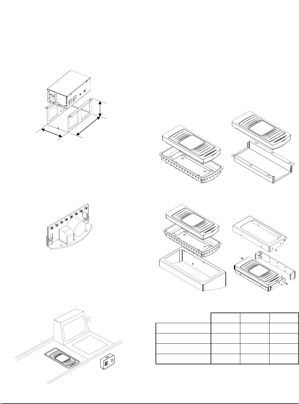
Options
The following options can be ordered:
ZBSTP-PK-B power pack mounting bracket
(Figure 2) enables the power pack to attach to the
underside of a countertop.
Figure 2. Power pack mounting bracket
ZBSTP-PP-IB indicator board (Figure 3) plugs
into the bottom of the antenna to provide an
audio/visual indication of operation. LEDs are
visible through the top of the antenna. A cable
connects the board to the power pack.
Figure 3. Indicator board
Remote Alarm Module (Figure 4) replaces the
indicator board to position status LEDs closer to
the operator. A cable connects the module to the
power pack.
Figure 4. Remote indicator module
Antenna mounting brackets (Figure 5) are used
to mount the antenna flush with the countertop,
under the countertop, or when counter space is not
available, over or on the side of the bagwell.
These brackets are as follows:
− ZBSTP-PP-B1 flush mount tray
− ZBSTP-PP-B2 under counter bracket
− ZBSTP-PP-B3 cantilever bracket (for bagwell)
− ZBSTP-PP-B4 flip bracket (for bagwell)
Note: Countertop mounting requires no
additional bracketry.
Figure 5. Antenna mounting brackets
LWH
Flush Mount Tray 430mm 201mm 56mm
Under Counter Brkt 397mm 226mm 57mm
Cantilever Bracket 451mm 236mm 125mm
Flip Down Bracket 425mm 195mm 54mm
Under Counter BracketFlush Mount Tray
Flip Down Bracket
Cantilever Bracket
4PLANNING GUIDE FOR BETA TEST
STP POWER PAD DEACTIVATOR
8000-2599-01, Rev. A
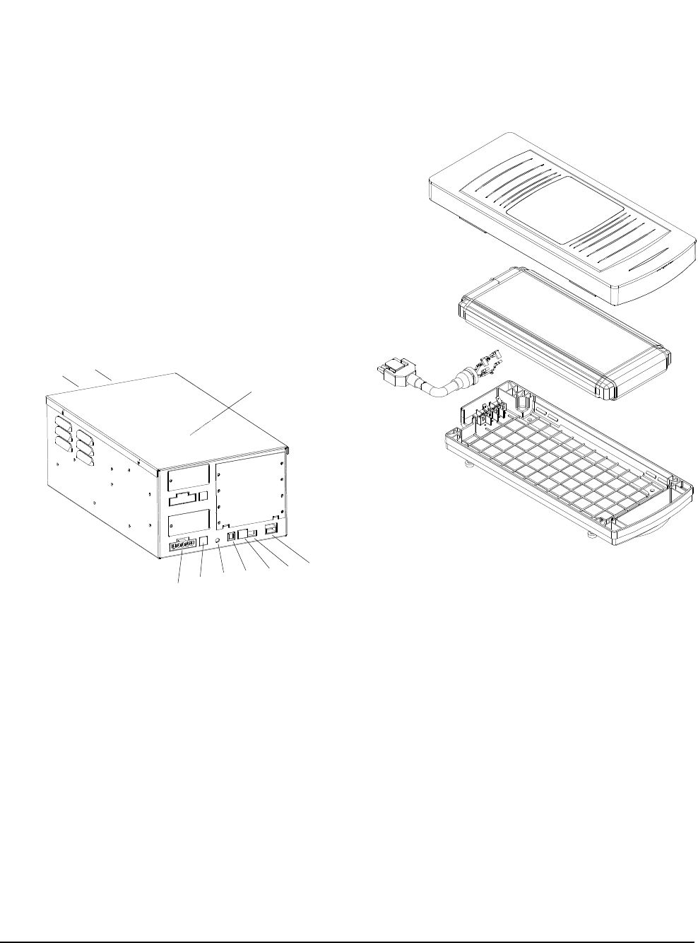
Component Description
ZBSTPPK1 power pack (Figure 6). The pack
contains the following components:
a. AC input. Automatically adjusts for any input
voltage from 100 to 250Vac and for 50/60Hz.
b. On/Off switch. Turns power on and off.
c. P16. Deactivation cable receptacle.
d. P15. Indicator board receptacle.
e. DS1. Power on indicator.
f. P12. RS-232 software configurator port.
g. P9. Scan Link I/O port.
h. SW1. DIP switches for ac phase and gain
adjustments.
i. TB1. RS485 port.
j. Antenna tuning jumpers. Inside the box.
Figure 6. Power pack components
Power Pad Antenna (Figure 7). Is a non-
serviceable iron core assembly inside a plastic
shell. The bottom of the antenna contains a well for
the optional audio/visual indicator board and a
receptacle for the deactivation cable.
Figure 7. Power Pad antenna
2.5m (8')
Antenna Cable
Antenna Winding
and Core
Lower Housing
Upper Housing
j
i
h
g
f
e
d
c
b
a

STP POWER PAD DEACTIVATOR
8000-2599-01, Rev. A PLANNING GUIDE FOR BETA TEST 5
IMPORTANT SAFEGUARDS
Please observe the following safeguards before
you begin installation or service.
o Hazardous areas.
DO NOT install deactivator in hazardous areas
where highly combustible or explosive products
are stored or used.
o RISK OF ELECTRIC SHOCK!
Keep the power cord and interconnect cable
away from cash drawers and other items whose
operation may pinch or otherwise damage
them. Failure to do so can result in damage to
equipment or injury to people nearby.
o Ac source must be:
− Isolated from neon signs, motors,
computers, cash registers, terminals, or
data communications equipment
− Unswitched with less than 0.5Vac between
neutral and ground
− Within 1.8m (6') of power pack to accom-
modate 3m (10') long power cord.
Each power pack requires its own electrical
outlet.
o Interference with nearby metal and
electronic equipment.
− Fields emitted by the antenna cannot pass
through metal. Also, ferrous metal surround-
ing the antenna can distort the field and
reduce detection range.
Note: If you must place the antenna on
ferrous metal, then place an aluminum plate
behind the antenna to minimize absorption
of the field.
− Computer monitors, TVs, switching power
supplies and neon displays can affect
deactivator operation. Keep the antenna
away from these devices whenever
possible.
o Interference with magnetic readers and CRT
monitors.
− Antenna fields may affect the operation of
magnetic check and card readers (alone or
in keyboards).
− Antenna fields may cause CRT images
within 1.8m (6') to quiver. LCD and LED
displays are not affected.
Note: If antenna fields cause interference, ask
the customer if they accept it. If not, move
the antenna to eliminate the interference. If
this cannot be done, contact your Sensor-
matic technical support specialist for guid-
ance.
Pre-Install Preparation
To ensure the deactivator performs reliably:
o Have electrical work comply with latest national
electrical code, national fire code, and all
applicable local codes and ordinances.
o Coordinate work with other trades to avoid
interference.
o Verify existing site conditions and coordinate
with the owner’s representative and appropriate
utilities as required.
o Obtain copies of all related plans, specifi-
cations, shop drawings and addenda to
schedule and coordinate related work.
o Thoroughly review the project to ensure that all
work meets or exceeds the above require-
ments. Bring alleged discrepancies to the
attention of Sensormatic Electronics.
Also, follow procedures listed next in this
document:
• Perform a site survey
• Note maximum pedestal separation at exits
• Ensure label application guidelines are followed
• Ensure scanning/deactivation guidelines are
followed.
6PLANNING GUIDE FOR BETA TEST
STP POWER PAD DEACTIVATOR
8000-2599-01, Rev. A
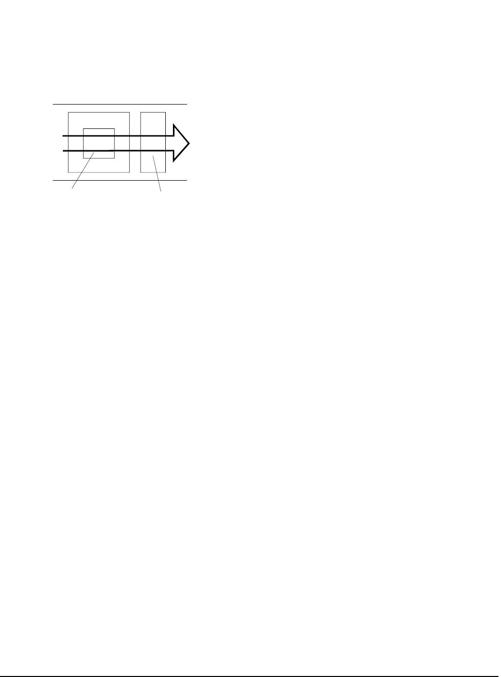
Site Survey
Placing the antenna immediately downstream from
the bar-code scanner (Figure 8) places the
deactivation field in line with the checker’s natural
arm movement.
Figure 8. Deactivator antenna location
To determine the best mounting solution, do the
following:
• Obtain a drawing showing the dimensions of
the checkstand.
• Describe the checkout process. If possible,
videotape the process for clarification.
• Photograph the antenna in its installed position.
Also note the following:
• If shelf or countertop is adjacent to the bar-
code scanner, install the antenna under or flush
in the countertop.
• Is the countertop made of ferrous metal? If it is,
and you must install the antenna on the
countertop, then place an aluminum plate
behind the antenna to minimize absorption of
the field.
• If installing the antenna in a bagwell, ensure the
prongs holding the bag will not shift and the bag
will be as close to the antenna as possible.
If wall of bagwell is steel, use 3/4-inch plywood
(not provided) to stiffen it and to provide a solid
anchor for bracket’s mounting screws (you may
have to remove the scanner to do this).
Plywood should be at least 22.9cm (9") wide.
Determine its length by measuring from top of
mounting bracket to base of wall inside counter.
• Metal around the antenna can deflect or distort
the deactivate field. Try pre-installing the
antenna to see the effects.
• The 2.3m (7.5') power cord cannot interfere
with the operation of cash drawers or conveyor
belts or interfere with operation, maintenance or
removal of equipment.
Forward this information to Corporate Technical
Support to establish a library of installations and to
facilitate support.
Note: If the mounting brackets available cannot be
used, consider a custom solution. A custom
solution involves a process that usually takes two
to three months from initial request to delivery, and
is as follows:
1. You initiate a request for a custom solution and
send site-specific data to Corporate Technical
Support.
2. Development team analyzes photographs of
the checkstand (videos are extremely helpful to
demonstrate merchandise handling).
3. In some cases, representatives from the team
conduct an on-site analysis to evaluate initial
proposals and gather additional data.
4. A Request for Product Modification (RFM) is
generated, formally requesting the development
of a new installation kit.
5. Engineering Design and Procurement acquires
a working prototype.
6. Development and field teams test the
prototype.
7. Design modifications occur based on test
results.
8. If necessary, a revised prototype is developed
and tested.
9. Start-up production includes finalizing docu-
mentation, placing orders, and first article
approval.
Note: The most effective installation integrates
deactivation with the scanning process. However, if
circumstances do not allow sufficient lead time for
developing a custom solution, consider integrating
deactivation with another step in the normal
product flow.
Bar-Code Scanner
Deactivator
Antenna

STP POWER PAD DEACTIVATOR
8000-2599-01, Rev. A PLANNING GUIDE FOR BETA TEST 7
Maximum Detector Separation
The Ultrastrip II Label is used with Ultra•Max EAS
detectors. Maximum pedestal separation for use
with the UltraStrip II label is as follows:
Ultra•Max Detector Pedestal
Separation
Pro•Max 2.3m (8')
Pro•Max II 2.3m (8')
EuroPro•Max III 2.3m (8')
Ultra•Post 1.8m (6')
StandAlone/Euro•Max 1.3m (4.5')
MAX Checkout (2 pedestals) 1.1m (3.6')
Label Application Guidelines
To ensure reliable deactivation, follow these
guidelines when applying UltraStrip II labels:
• Always place label on a flat, clean, dry surface,
as close to UPC bar-code as possible, but no
more than 5cm (2") from bar-code.
• Apply the label to same surface as the barcode
whenever possible.
• Do not cover any part of the bar code or its
numbers.
• Do not cover any text printed on the item such
as directions, ingredients, lot numbers, or
expiration dates.
• Do not bend or pinch the label. Discard all bent
or damaged labels.
• Do not apply the label to a curved surface.
However, the label can be applied parallel to
cylindrical items at least 76mm (3") in diameter.
Never apply the label to these items diagonally
or horizontally.
• Do not apply the label to vinyl or leather. The
label’s adhesive can damage these items.
• Use an offset label when applying directly to
ferro-magnetic metallic items such as metal fan
blades and light fixtures.
• Do not apply the label near strong magnets
such as those in loudspeakers, or within 13mm
(0.5") of small magnets.
About source tagging...
Source tagging is the process of applying labels
during the manufacturing process, typically inside
product packaging. All standard source tagging
guidelines apply for this deactivator. For more
information, contact your Sensormatic account
manager.

8PLANNING GUIDE FOR BETA TEST
STP POWER PAD DEACTIVATOR
8000-2599-01, Rev. A
Scanning/Deactivation
Guidelines
Reliable label deactivation depends on a good
scanning technique. Read the following guidelines
for routine scanning/deactivation and scanning/
deactivation of pre-recorded magnetic media.
Routine Scanning/Deactivation
To help cashiers develop a proper scanning
rhythm, select ten “labeled” items that represent a
cross section of the store’s most frequently sold
items. Cashiers should practice scanning and
deactivating these items using the steps listed
below.
1. Locate the scanner’s the sweet spot. The sweet
spot provides optimal scanning recognition.
Some scanners have markings such as arrows
or tightly spaced lines to identify this spot.
2. Position items before presenting them to the
scanner. Cashiers should use both hands to
position heavy or bulky items. For tall items,
they should keep their wrists straight to avoid
tipping the item and lifting the bar code out of
the scan zone. This technique also eliminates
wrist stress.
3. Both the scanner’s sweet spot and the
antennas’s magnetic field are aligned to the
cashier’s normal scanning motion. The
antenna’s field extends 15cm (6") above its
surface. Move merchandise horizontally along
the scan/ deactivation pathway (Figure 9),
keeping the label and barcode within 15cm (6")
of the countertop; do not lift items away from
the scanner.
Figure 9. Scanning/Deactivation pathway
Remember: When a label is detected, the
antenna’s green LED turns red and it emits a
4. Avoid wasted motion. Avoid turning or reposi-
tioning items during scanning/deactivation.
5. Verify deactivation. Have the cashier position
the item so that the bar code is close to the
antenna surface. If the label was correctly
deactivated, the LED will remain green. If the
LED turns red, the label was not deactivated
initially, but has been deactivated during this
verification process.
Note: Use this step for training purposes only.
Once a consistent scanning/deactivation
technique is developed, cashiers can be
confident of reliable label deactivation on the
first pass.
6. Repeat the process. Cashiers should practice
until a smooth rhythm is developed and they
should become familiar with bar code location
on high volume items.
Note: A ZKWACT ActivatorWand or ZKCDACT
Activator Pad can be used during training to
reactivate the label. You can obtain it by contacting
your Sensormatic Customer Support Specialist.
A special note about bagwells:
If the antenna is to be located within the bagwell,
follow these special steps to ensure deactivation:
1. Position the bag rack so the bag lines up with
the antenna (Figure 10).
2. If the bag rack is removeable, check its
alignment periodically since it might be moved.
Figure 10. Bag alignment
Deactivator
Antenna
Bar-Code Scanner
STP POWER PAD DEACTIVATOR
8000-2599-01, Rev. A PLANNING GUIDE FOR BETA TEST 9
Scanning/Deactivation and
Pre-Recorded Magnetic Media
The antenna’s magnetic field can affect pre-
recorded magnetic media such as videotapes,
audiotapes, computer hardrives, software on
floppy disks, and credit cards. Use the following
guidelines to reduce the possibility of affecting pre-
recorded media:
• Do not place credit cards near the antenna
during the deactivation process. Be sure that
customers do not place or hold cards near the
antenna.
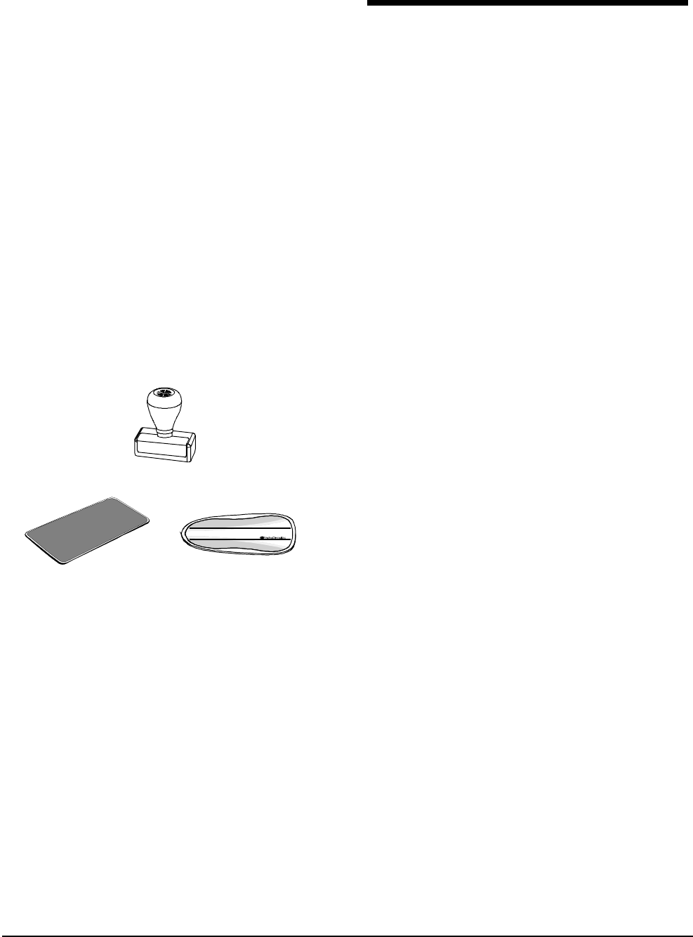
• Do not place laptop computers on the antenna.
• If not using the magnetic media safe mode,
then use a contact deactivator to deactivate
pre-recorded items—before they are scanned.
Examples of contact deactivators are shown in
Figure 11.
Figure 11. Examples of contact deactivators
Specifications
Electrical
AC line input ...................... 100–250V~ (50/60Hz)
AC line current................... 15Arms (short term
operation, 1
deactivation every sec)
2.0Arms (long term
avg, 1 deactivation
every 12 sec)
Transmitter
Output................................ Pulsed, synchronized
to AC line
Current............................... 0.5Apk (nominal)
Operating frequency.......... 58 kHz
Receiver
Center frequency............... 58 kHz
Deactivation
Output................................ Line resonant @ 50Hz
or 60Hz (?)
Pulse width ........................ 250ms (?)
Current............................... 7Arms (+10/-15%)
50Hz (?)
15Arms (+10/-15%)
60Hz (?)
Line Synchronization
50Hz Settings .................... 75Hz (phase A,B,C)
60Hz Settings .................... 90Hz (phase A,B,C)
Zero line crossing .............. ±4000µs from center
RS232 Communication Port:
Settings .......................... 9600, 8, N, 1
Connector....................... Four position modular
phone jack
ZBMMECD Contact
Deactivator
ZK252 Contact
Deactivator
ZK30 Hand Stamp Deactivator

10 PLANNING GUIDE FOR BETA TEST
STP POWER PAD DEACTIVATOR
8000-2599-01, Rev. A
Auxiliary I/O
This I/O port is user configurable for internal power
or external drive options. Vcc and Ground are
available at the port pins.
Inputs (two).........................Opto-coupled diode
10mA, typical /60mA
max drive
Output.................................Opto-coupled transistor
max capacity 150mA
Connector...........................8-position modular
phone jack
RS485 ................................(?)
Environmental
Operating temperature.......0°C to 50°C
(32°F to 122°F)
Non-operating temp. ..........–40°C to 70°C
(–40°F to 158°F)
Relative humidity................0 to 90% non-
condensing
Mechanical
Power pack:
Weight.............................4 kg (9 lbs)
Length.............................38 cm (14.9")
Width...............................22.6 cm (9")
Height..............................14.4 cm (5.5")
Power cord .........................3 m (10')
Power Pad Antenna:
Weight.............................10 kg (22 lbs)
Length .............................39.3 cm (15.5")
Width...............................17 cm (6.75")
Height..............................5.6 cm (2.2")
Remote Indicator Module:
Length .............................82.5mm (3.3")
Width...............................59mm (2.3")
Depth ..............................30mm (1.2")
Declarations
Regulatory Compliance
Emissions .......................... 47 CFR, Part 15,
Class A
ETS 300 330
ETS 300 683
Bapt 222 (Germany)
EN61000-3-2
EN61000-3-3
VDE 0848
Safety................................. UL1950
CSA C22.2 No 950
EN 60 950
FCC COMPLIANCE: This equipment complies with Part 15
of the FCC rules for intentional radiators and Class A digital
devices when installed and used in accordance with the
instruction manual. Following these rules provides reasonable
protection against harmful interference from equipment
operated in a commercial area. This equipment should not be
installed in a residential area as it can radiate radio frequency
energy that could interfere with radio communications, a
situation the user would have to fix at their own expense.
EQUIPMENT MODIFICATION CAUTION: Equipment
changes or modifications not expressly approved by
Sensormatic Electronics Corporation, the party responsible
for FCC compliance, could void the user's authority to operate
the equipment and could create a hazardous condition.
Other Declarations
WARRANTY DISCLAIMER: Sensormatic Electronics
Corporation makes no representation or warranty with respect
to the contents hereof and specifically disclaims any implied
warranties of merchantability or fitness for any particular
purpose. Further, Sensormatic Electronics Corporation
reserves the right to revise this publication and make changes
from time to time in the content hereof without obligation of
Sensormatic Electronics Corporation to notify any person of
such revision or changes.
LIMITED RIGHTS NOTICE: For units of the Department of
Defense, all documentation and manuals were developed at
private expense and no part of it was developed using
Government Funds. The restrictions governing the use and
disclosure of technical data marked with this legend are set
forth in the definition of "limited rights" in paragraph (a) (15)
of the clause of DFARS 252.227.7013. Unpublished - rights
reserved under the Copyright Laws of the United States.