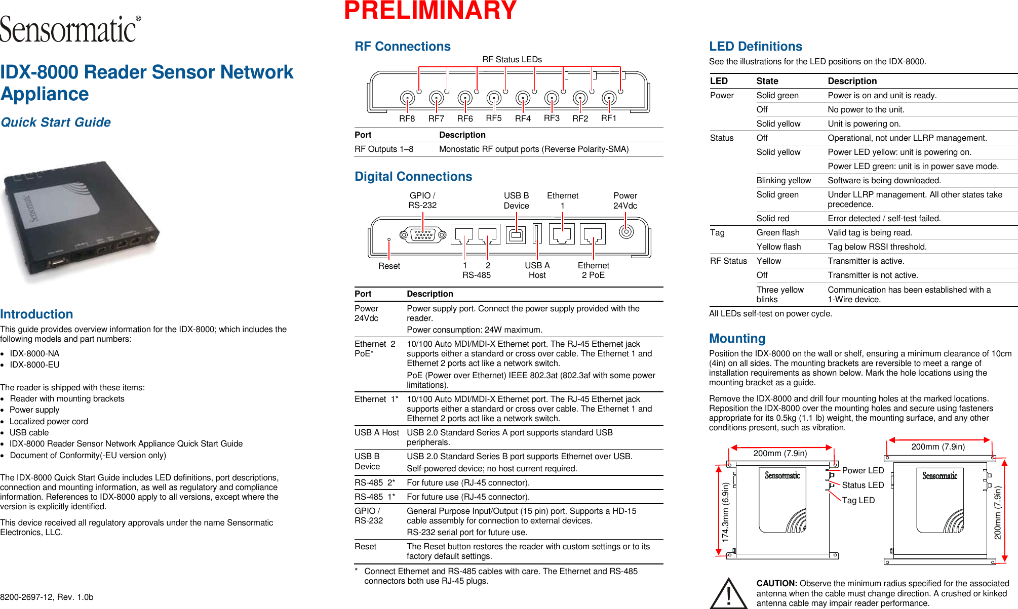
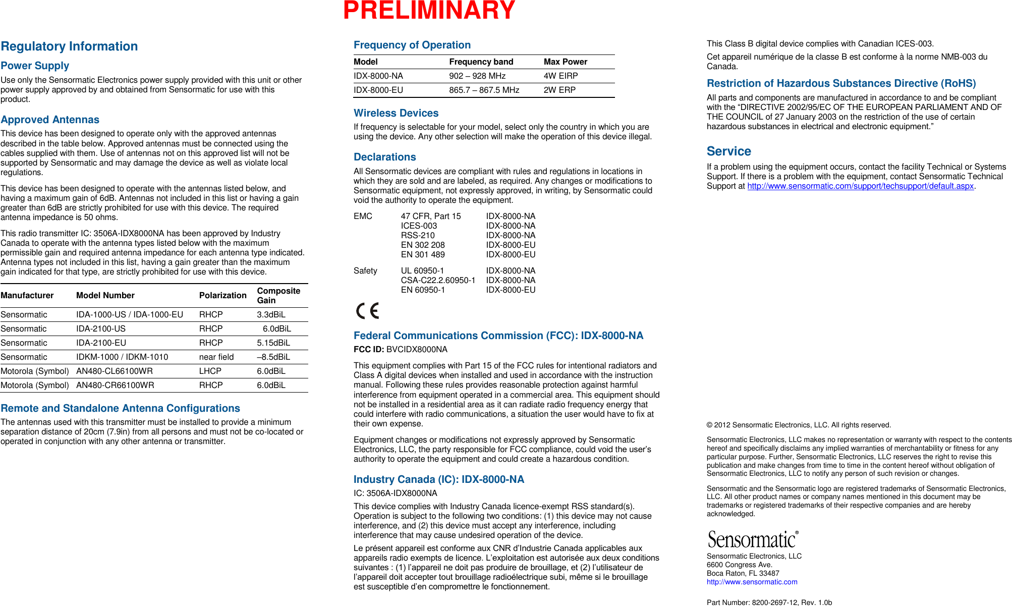
Tyco Safety Sensormatic IDX8000NA PART 15.247 SPREAD SPECTRUM TRANSMITTER, RFID READER User Manual

Tyco Safety Products/Sensormatic PART 15.247 SPREAD SPECTRUM TRANSMITTER, RFID READER

User Manual

 PRELIMINARY  IDX-8000 Reader Sensor Network Appliance Quick Start Guide  Introduction This guide provides overview information for the IDX-8000; which includes the following models and part numbers:   IDX-8000-NA   IDX-8000-EU The reader is shipped with these items:   Reader with mounting brackets   Power supply   Localized power cord   USB cable   IDX-8000 Reader Sensor Network Appliance Quick Start Guide   Document of Conformity(-EU version only) The IDX-8000 Quick Start Guide includes LED definitions, port descriptions, connection and mounting information, as well as regulatory and compliance information. References to IDX-8000 apply to all versions, except where the version is explicitly identified. This device received all regulatory approvals under the name Sensormatic Electronics, LLC.  8200-2697-12, Rev. 1.0b RF Connections  Port Description RF Outputs 1–8 Monostatic RF output ports (Reverse Polarity-SMA)  Digital Connections  Port Description Power 24Vdc Power supply port. Connect the power supply provided with the reader. Power consumption: 24W maximum. Ethernet  2 PoE* 10/100 Auto MDI/MDI-X Ethernet port. The RJ-45 Ethernet jack supports either a standard or cross over cable. The Ethernet 1 and Ethernet 2 ports act like a network switch. PoE (Power over Ethernet) IEEE 802.3at (802.3af with some power limitations). Ethernet  1* 10/100 Auto MDI/MDI-X Ethernet port. The RJ-45 Ethernet jack supports either a standard or cross over cable. The Ethernet 1 and Ethernet 2 ports act like a network switch. USB A Host USB 2.0 Standard Series A port supports standard USB peripherals. USB B Device USB 2.0 Standard Series B port supports Ethernet over USB. Self-powered device; no host current required. RS-485  2* For future use (RJ-45 connector). RS-485  1* For future use (RJ-45 connector). GPIO / RS-232 General Purpose Input/Output (15 pin) port. Supports a HD-15 cable assembly for connection to external devices. RS-232 serial port for future use. Reset The Reset button restores the reader with custom settings or to its factory default settings. *  Connect Ethernet and RS-485 cables with care. The Ethernet and RS-485 connectors both use RJ-45 plugs.  LED Definitions  See the illustrations for the LED positions on the IDX-8000. LED State Description Power Solid green Power is on and unit is ready.  Off No power to the unit. Solid yellow Unit is powering on. Status Off Operational, not under LLRP management. Solid yellow Power LED yellow: unit is powering on.  Power LED green: unit is in power save mode. Blinking yellow Software is being downloaded. Solid green Under LLRP management. All other states take precedence. Solid red Error detected / self-test failed. Tag Green flash Valid tag is being read. Yellow flash Tag below RSSI threshold. RF Status Yellow Transmitter is active.  Off Transmitter is not active.  Three yellow blinks Communication has been established with a 1-Wire device. All LEDs self-test on power cycle. Mounting Position the IDX-8000 on the wall or shelf, ensuring a minimum clearance of 10cm (4in) on all sides. The mounting brackets are reversible to meet a range of installation requirements as shown below. Mark the hole locations using the mounting bracket as a guide. Remove the IDX-8000 and drill four mounting holes at the marked locations. Reposition the IDX-8000 over the mounting holes and secure using fasteners appropriate for its 0.5kg (1.1 lb) weight, the mounting surface, and any other conditions present, such as vibration.  CAUTION: Observe the minimum radius specified for the associated antenna when the cable must change direction. A crushed or kinked antenna cable may impair reader performance. 200mm (7.9in) 174.3mm (6.9in) Power LED Status LED Tag LED 200mm (7.9in) 200mm (7.9in) RF Status LEDs RF1 RF2 RF3 RF4 RF5 RF6 RF7 RF8 Power 24Vdc Ethernet 1 GPIO / RS-232 Ethernet 2 PoE 1        2 RS-485 USB B Device USB A Host Reset
 PRELIMINARY Regulatory Information Power Supply Use only the Sensormatic Electronics power supply provided with this unit or other power supply approved by and obtained from Sensormatic for use with this product. Approved Antennas This device has been designed to operate only with the approved antennas described in the table below. Approved antennas must be connected using the cables supplied with them. Use of antennas not on this approved list will not be supported by Sensormatic and may damage the device as well as violate local regulations. This device has been designed to operate with the antennas listed below, and having a maximum gain of 6dB. Antennas not included in this list or having a gain greater than 6dB are strictly prohibited for use with this device. The required antenna impedance is 50 ohms. This radio transmitter IC: 3506A-IDX8000NA has been approved by Industry Canada to operate with the antenna types listed below with the maximum permissible gain and required antenna impedance for each antenna type indicated. Antenna types not included in this list, having a gain greater than the maximum gain indicated for that type, are strictly prohibited for use with this device. Manufacturer Model Number Polarization Composite Gain Sensormatic IDA-1000-US / IDA-1000-EU RHCP 3.3dBiL Sensormatic IDA-2100-US RHCP 6.0dBiL Sensormatic IDA-2100-EU RHCP 5.15dBiL Sensormatic IDKM-1000 / IDKM-1010 near field –8.5dBiL Motorola (Symbol) AN480-CL66100WR LHCP 6.0dBiL  Motorola (Symbol) AN480-CR66100WR RHCP 6.0dBiL Remote and Standalone Antenna Configurations The antennas used with this transmitter must be installed to provide a minimum separation distance of 20cm (7.9in) from all persons and must not be co-located or operated in conjunction with any other antenna or transmitter. Frequency of Operation Model Frequency band Max Power IDX-8000-NA 902 – 928 MHz 4W EIRP IDX-8000-EU 865.7 – 867.5 MHz 2W ERP Wireless Devices If frequency is selectable for your model, select only the country in which you are using the device. Any other selection will make the operation of this device illegal. Declarations All Sensormatic devices are compliant with rules and regulations in locations in which they are sold and are labeled, as required. Any changes or modifications to Sensormatic equipment, not expressly approved, in writing, by Sensormatic could void the authority to operate the equipment.  EMC  47 CFR, Part 15  IDX-8000-NA   ICES-003  IDX-8000-NA   RSS-210  IDX-8000-NA   EN 302 208  IDX-8000-EU   EN 301 489  IDX-8000-EU Safety   UL 60950-1  IDX-8000-NA   CSA-C22.2.60950-1  IDX-8000-NA    EN 60950-1  IDX-8000-EU  Federal Communications Commission (FCC): IDX-8000-NA FCC ID: BVCIDX8000NA This equipment complies with Part 15 of the FCC rules for intentional radiators and Class A digital devices when installed and used in accordance with the instruction manual. Following these rules provides reasonable protection against harmful interference from equipment operated in a commercial area. This equipment should not be installed in a residential area as it can radiate radio frequency energy that could interfere with radio communications, a situation the user would have to fix at their own expense. Equipment changes or modifications not expressly approved by Sensormatic Electronics, LLC, the party responsible for FCC compliance, could void the user’s authority to operate the equipment and could create a hazardous condition. Industry Canada (IC): IDX-8000-NA IC: 3506A-IDX8000NA This device complies with Industry Canada licence-exempt RSS standard(s). Operation is subject to the following two conditions: (1) this device may not cause interference, and (2) this device must accept any interference, including interference that may cause undesired operation of the device. Le présent appareil est conforme aux CNR d’Industrie Canada applicables aux appareils radio exempts de licence. L’exploitation est autorisée aux deux conditions suivantes : (1) l’appareil ne doit pas produire de brouillage, et (2) l’utilisateur de l’appareil doit accepter tout brouillage radioélectrique subi, même si le brouillage est susceptible d’en compromettre le fonctionnement. This Class B digital device complies with Canadian ICES-003. Cet appareil numérique de la classe B est conforme à la norme NMB-003 du Canada. Restriction of Hazardous Substances Directive (RoHS) All parts and components are manufactured in accordance to and be compliant with the “DIRECTIVE 2002/95/EC OF THE EUROPEAN PARLIAMENT AND OF THE COUNCIL of 27 January 2003 on the restriction of the use of certain hazardous substances in electrical and electronic equipment.” Service If a problem using the equipment occurs, contact the facility Technical or Systems Support. If there is a problem with the equipment, contact Sensormatic Technical Support at http://www.sensormatic.com/support/techsupport/default.aspx.               © 2012 Sensormatic Electronics, LLC. All rights reserved. Sensormatic Electronics, LLC makes no representation or warranty with respect to the contents hereof and specifically disclaims any implied warranties of merchantability or fitness for any particular purpose. Further, Sensormatic Electronics, LLC reserves the right to revise this publication and make changes from time to time in the content hereof without obligation of Sensormatic Electronics, LLC to notify any person of such revision or changes. Sensormatic and the Sensormatic logo are registered trademarks of Sensormatic Electronics, LLC. All other product names or company names mentioned in this document may be trademarks or registered trademarks of their respective companies and are hereby acknowledged.  Sensormatic Electronics, LLC 6600 Congress Ave.  Boca Raton, FL 33487 http://www.sensormatic.com Part Number: 8200-2697-12, Rev. 1.0b

Navigation menu