Tyco Mx4428 Users Manual LT0273 MXP ENGINEERING/TECHNICAL
MX4428 to the manual 157f9f00-25a6-45a4-a0ca-0313a0ae3a0d
2015-02-03
: Tyco Tyco-Mx4428-Users-Manual-460878 tyco-mx4428-users-manual-460878 tyco pdf
Open the PDF directly: View PDF ![]() .
.
Page Count: 134 [warning: Documents this large are best viewed by clicking the View PDF Link!]
- Chapter 1 INTRODUCTION
- 1.1 ABOUT THIS MANUAL
- 1.2 ASSOCIATED DOCUMENTATION
- 1.3 SPECIFICATIONS
- 1.4 TERMINOLOGY
- Chapter 2 RESPONDER LOOP DESIGN CONSIDERATIONS
- Chapter 3 DEVICE INFORMATION AND PROGRAMMING
- 3.1 DEVICE TYPES
- 3.2 DEVICE HANDLING CAPABILITY
- 3.3 OUTPUT CONTROL
- 3.4 DETECTOR PARAMETER SETTINGS SUMMARY
- 3.5 DEVICE INSTALLATION
- 3.6 MX4428 PROGRAMMING
- 3.7 814H HEAT DETECTOR
- 3.8 814I IONISATION SMOKE DETECTOR
- 3.9 814PH PHOTOELECTRIC SMOKE & HEAT DETECTOR & 814P PHOTOELECTRIC SMOKE ONLY DETECTOR
- 3.10 814CH CARBON MONOXIDE + HEAT DETECTOR
- 3.11 MUB UNIVERSAL BASE
- 3.12 5BI ISOLATOR BASE
- 3.13 814RB RELAY BASE
- 3.14 814SB SOUNDER BASE
- 3.15 MKII SOUNDER BASE
- 3.16 MIM800 AND MIM801 MINI INPUT MODULES
- 3.17 CIM800 CONTACT INPUT MODULE
- 3.18 CP820 MANUAL CALL POINT
- 3.19 FP0838 / FP0839 MANUAL CALL POINTS
- 3.20 DIM800 DETECTOR INPUT MONITOR
- 3.21 RIM800 RELAY INTERFACE MODULE
- 3.22 SNM800 SOUNDER NOTIFICATION MODULE
- 3.23 LPS800 LOOP POWERED SOUNDER MODULE
- 3.24 VLC-800MX VESDA LASERCOMPACT
- 3.25 AVF / RAD / SAD / FLOWSWITCH DELAYS
- Chapter 4 ANALOGUE LOOP DESIGN CONSIDERATIONS
- Chapter 5 MXP CURRENT CONSUMPTION
- Chapter 6 EVENT LOG AND STATUS AT MX4428
- Chapter 7 MXP TECHNICAL DESCRIPTION
- Chapter 8 MXP DIAGNOSTIC TERMINAL
- 8.1 MXP DIAGNOSTIC TERMINAL OPERATION
- 8.1.1 INTRODUCTION
- 8.1.2 MENU OF COMMANDS
- 8.1.3 SELECTING POINTS FOR MONITORING
- 8.1.4 DISPLAYING DEVICE ANALOGUE VALUES - CV, TV, ETC
- 8.1.4.1 Heat Sensor of 814H, 814PH, and 814CH
- 8.1.4.2 Photo Sensor of 814PH
- 8.1.4.3 Carbon Monoxide Sensor of 814CH
- 8.1.4.4 814I Ionisation Detector
- 8.1.4.5 MIM800 Mini Input Module
- 8.1.4.6 MIM801 Mini Input Module
- 8.1.4.7 CP820 Manual Callpoint
- 8.1.4.8 CIM800 Contact Input Module
- 8.1.4.9 DIM800 Detector Input Module
- 8.1.4.10 RIM800 Relay Interface Module
- 8.1.4.11 SNM800 Sounder Notification Module
- 8.1.4.12 LPS800 Sounder Notification Module
- 8.1.4.13 VLC800 Vesda Laser Compact
- 8.1.5 ST (STATUS COMMAND)
- 8.1.6 ANALOG LOOP DIAGNOSTICS
- 8.1.7 ADVANCED COMMANDS
- 8.1.8 MX4428 DIAGNOSTICS
- 8.1.9 MXP EVENT LOG
- 8.2 FLASH PROGRAMMING
- 8.1 MXP DIAGNOSTIC TERMINAL OPERATION
- Chapter 9 DEVICE PROCESSING
- 9.1 EXPONENTIAL FILTER
- 9.2 STEP LIMITING FILTER
- 9.3 HEAT PROCESSING
- 9.4 PHOTO PROCESSING
- 9.5 CO PROCESSING
- 9.6 IONISATION PROCESSING
- 9.7 MIM800 / CIM800 / MIM801 PROCESSING
- 9.8 DIM PROCESSING
- 9.9 RIM PROCESSING
- 9.10 SNM PROCESSING
- 9.11 LPS PROCESSING
- 9.12 VLC800 PROCESSING
- 9.13 FILTER STEP LIMITS
- 9.14 ZONE ALARM TEST
- 9.15 ZONE FAULT TEST
- 9.16 AUTOTEST AND SYSTEM TEST
- 9.17 NON LATCHING TEST MODE
- 9.18 COMMISSION MODE
- 9.19 FAST POINT TEST
- 9.20 SLOW POINT TEST
- 9.21 SUMMARY OF ALL TEST MODES
- 9.22 ANCILLARY FILTERING
- 9.23 RESET
- 9.24 DEVICE INITIALISATION AND POLLING
- 9.25 SOFTWARE VERSIONS
- Chapter 10 MXP LOOP FILTER BOARD

MX4428
MXP ENGINEERING / TECHNICAL MANUAL
MX4428 PRODUCT MANUAL
VOLUME 11
Document Number: LT0273
Issue 1.5; 24 March 2006
- APPROVALS -
AUSTRALIAN STANDARD AS4428.1
- SSL Listing Number ....................................................................................... afp1446
NEW ZEALAND STANDARD NZS4512-1997 (INCL AMDT 1 & 2)
- FPA (NZ) Listing number ................................................................................. VF/117
AS/NZS 3548 1995 CLASS A
The 4100MXP is a product of
Tyco Safety Products
211 Maces Road
Christchurch 8030
NEW ZEALAND
Phone +64-3-389 5096
Fax +64-3-389 5938
COPYRIGHT (C) 2003,2004
Information contained in this document is subject to copyright, and shall not be reproduced in any
form whatsoever, without the written consent of Tyco Services Fire & Safety.
Information contained in this document is believed to be accurate and reliable, however Tyco
Services Fire & Safety reserves the right to change the content without prior notice.

MX4428 MXP Engineering /Technical Manual Document: LT0273
Page ii 24 March 2006 Issue 1.5
NON-DISCLOSURE AGREEMENT
Tyco (THE COMPANY) and the User of this/these document(s) desire to share proprietary technical information
concerning electronic systems.
For this reason the company is disclosing to the User information in the form of this/these document(s). In as
much as the company considers this information to be proprietary and desires that it be maintained in confidence,
it is hereby agreed by the User that such information shall be maintained in confidence by the User for a period of
TEN YEARS after the issue date and only be used for the purpose for which it was supplied.
During this period, the User shall not divulge such information to any third party without the prior written consent
of the company and shall take reasonable efforts to prevent any unauthorised disclosure by its employees.
However, the User shall not be required to keep such information in confidence if it was in their possession prior
to its receipt from the company; if it is or becomes public knowledge without the fault of the User; or the
information becomes available on an unrestricted basis from a third party having a legal right to disclose such
information.
The User's receipt and retention of this information constitutes acceptance of these terms.
This information is copyright and shall not be reproduced in any form whatsoever.
END USER LIABILITY DISCLAIMER
The MX4428 Fire Indicator Panel provides a configuration programming facility, which may be accessed via a
programming terminal using a password. Because this programming facility allows the user to define in detail the
operation of the MX4428 System being customised, changes may be made by the user that prevent this
installation from meeting statutory requirements.
The Company, therefore cannot accept any responsibility as to the suitability of the functions generated by the
user using this programming facility.
AMENDMENT LOG
21 March 01 Issue 1.0 Original
24 April 03 Issue 1.1 Updated DIM800 Compatibility, added VLC800, LPS800, Alarm
Tests
11 March 04 Issue 1.2 DIM800 with s/c fault option. Added "specs", noted source of
MXPPROG, updated MXP software version history.
28 January 05 Issue 1.3 Added requirements for AS1670.1. Noted DIM800 supply
supervision threshold is not adjustable. Added MIM800 max cable
length on inputs to its specs. Updated Table 3-2. Added 5B,
replaced 814IB with 5BI.
Noted MkII Sounder Base has AS2220 and ISO tones. Added note
re acceptable type mismatches. Added reference to software
version 1.12.
28 October 05 Issue 1.4 Added 614CH, 614I, 614P, System Sensor 885WP-B detectors to
Table 3-4.
24 March 06 Issue 1.5 Added 614T Section 3.20.3. Added 814P Section 3.9, etc. Added
Loop Filter Board, Chapter 10.
TRADEMARKS
VESDA is a registered trademark of Vision Systems.

Document: LT0273 MX4428 MXP Engineering / Technical Manual
Issue 1.5 24 March 2006 Page iii
TABLE OF CONTENTS
NON-DISCLOSURE AGREEMENT....................................................................................................... II
END USER LIABILITY DISCLAIMER.................................................................................................... II
AMENDMENT LOG .............................................................................................................................. II
TRADEMARKS ..................................................................................................................................... II
CHAPTER 1 INTRODUCTION ...............................................................................1-1
1.1 ABOUT THIS MANUAL.........................................................................................................1-2
1.2 ASSOCIATED DOCUMENTATION.......................................................................................1-2
1.2.1 PRODUCT RELATED ....................................................................................................1-2
1.2.2 STANDARD RELATED ..................................................................................................1-3
1.3 SPECIFICATIONS .................................................................................................................1-3
1.4 TERMINOLOGY.....................................................................................................................1-4
CHAPTER 2 RESPONDER LOOP DESIGN CONSIDERATIONS .........................2-1
2.1 MXP APPLICATION CONSIDERATIONS ............................................................................2-2
2.2 "LOGICAL" RESPONDERS .................................................................................................2-3
2.2.1 THEORY......................................................................................................................... 2-3
2.2.2 LOGICAL RESPONDERS.............................................................................................. 2-3
2.2.3 POINT TO CIRCUIT TO ZONE MAPPING .................................................................... 2-5
2.3 IMPLICATIONS TO SYSTEM DESIGN................................................................................. 2-6
CHAPTER 3 DEVICE INFORMATION AND PROGRAMMING..............................3-1
3.1 DEVICE TYPES ..................................................................................................................... 3-2
3.1.1 MX DEVICES.................................................................................................................. 3-2
3.2 DEVICE HANDLING CAPABILITY .......................................................................................3-7
3.2.1 OVERVIEW ....................................................................................................................3-7
3.2.2 DC LOAD........................................................................................................................ 3-8
3.2.3 AC LOADING.................................................................................................................. 3-8
3.2.4 ISOLATOR BASE LOADING.......................................................................................... 3-9
3.2.5 EXAMPLE....................................................................................................................... 3-9
3.3 OUTPUT CONTROL............................................................................................................3-10
3.3.1 PROGRAMMING.......................................................................................................... 3-11
3.3.2 OUTPUT STATE UNDER EXCEPTIONAL CIRCUMSTANCES ................................. 3-11
3.4 DETECTOR PARAMETER SETTINGS SUMMARY........................................................... 3-12
3.5 DEVICE INSTALLATION.....................................................................................................3-13
3.5.1 PRECAUTIONS............................................................................................................ 3-13
3.5.2 MOUNTING ..................................................................................................................3-13
3.5.3 ADDRESS & LED BLINK PROGRAMMING ................................................................3-13
3.6 MX4428 PROGRAMMING................................................................................................... 3-14
3.7 814H HEAT DETECTOR .....................................................................................................3-15
3.7.1 GENERAL..................................................................................................................... 3-15
3.7.2 814H SPECIFICATIONS..............................................................................................3-15
3.7.3 MX4428 PROGRAMMING OPTIONS - 814H.............................................................. 3-15
3.8 814I IONISATION SMOKE DETECTOR ............................................................................. 3-17
3.8.1 GENERAL..................................................................................................................... 3-17
3.8.2 814I SPECIFICATIONS................................................................................................3-17
3.8.3 MX4428 PROGRAMMING OPTIONS - 814I................................................................ 3-17
3.9 814PH PHOTOELECTRIC SMOKE & HEAT DETECTOR & 814P PHOTOELECTRIC
SMOKE ONLY DETECTOR ............................................................................................................3-19
3.9.1 GENERAL..................................................................................................................... 3-19
3.9.2 814PH & 814P SPECIFICATIONS............................................................................... 3-19
3.9.3 MX4428 PROGRAMMING OPTIONS - 814PH/814P .................................................. 3-19
3.10 814CH CARBON MONOXIDE + HEAT DETECTOR.......................................................... 3-23
3.10.1 GENERAL..................................................................................................................... 3-23
3.10.2 814CH SPECIFICATIONS ...........................................................................................3-23
3.10.3 MX4428 PROGRAMMING OPTIONS - 814CH ........................................................... 3-23
MX4428 MXP Engineering /Technical Manual Document: LT0273
Page iv 24 March 2006 Issue 1.5
3.11 MUB UNIVERSAL BASE ....................................................................................................3-25
3.11.1 GENERAL..................................................................................................................... 3-25
3.11.2 MUB AND 5B WIRING ................................................................................................. 3-25
3.11.3 REMOTE INDICATOR WIRING...................................................................................3-25
3.12 5BI ISOLATOR BASE......................................................................................................... 3-26
3.12.1 GENERAL..................................................................................................................... 3-26
3.12.2 SPECIFICATIONS........................................................................................................ 3-26
3.12.3 WIRING ........................................................................................................................3-26
3.13 814RB RELAY BASE..........................................................................................................3-28
3.13.1 GENERAL..................................................................................................................... 3-28
3.13.2 SPECIFICATIONS........................................................................................................ 3-28
3.13.3 WIRING ........................................................................................................................3-28
3.14 814SB SOUNDER BASE ....................................................................................................3-30
3.14.1 GENERAL..................................................................................................................... 3-30
3.14.2 SPECIFICATIONS........................................................................................................ 3-30
3.14.3 WIRING ........................................................................................................................3-30
3.15 MKII SOUNDER BASE........................................................................................................ 3-31
3.15.1 GENERAL..................................................................................................................... 3-31
3.15.2 SPECIFICATIONS........................................................................................................ 3-31
3.15.3 WIRING ........................................................................................................................3-31
3.16 MIM800 AND MIM801 MINI INPUT MODULES..................................................................3-32
3.16.1 GENERAL..................................................................................................................... 3-32
3.16.2 MIM800 / MIM801 SPECIFICATIONS .........................................................................3-32
3.16.3 FIELD WIRING .............................................................................................................3-33
3.16.4 MX4428 PROGRAMMING OPTIONS - MIM800 / MIM801 .........................................3-33
3.16.5 MX4428 PROGRAMMING OPTIONS - MIM801.......................................................... 3-34
3.17 CIM800 CONTACT INPUT MODULE.................................................................................. 3-35
3.17.1 GENERAL..................................................................................................................... 3-35
3.17.2 CIM800 SPECIFICATIONS.......................................................................................... 3-35
3.17.3 FIELD WIRING .............................................................................................................3-36
3.17.4 MX4428 PROGRAMMING OPTIONS - CIM800..........................................................3-36
3.18 CP820 MANUAL CALL POINT...........................................................................................3-38
3.18.1 GENERAL..................................................................................................................... 3-38
3.18.2 MX4428 PROGRAMMING OPTIONS - CP820............................................................ 3-38
3.19 FP0838 / FP0839 MANUAL CALL POINTS .......................................................................3-39
3.19.1 GENERAL..................................................................................................................... 3-39
3.19.2 MX4428 PROGRAMMING OPTIONS - FP0838 / FP0839 .......................................... 3-39
3.20 DIM800 DETECTOR INPUT MONITOR..............................................................................3-40
3.20.1 GENERAL..................................................................................................................... 3-40
3.20.2 DIM800 SPECIFICATIONS.......................................................................................... 3-41
3.20.3 DIM800 DETECTOR COMPATIBILITY........................................................................ 3-42
3.20.4 MX4428 PROGRAMMING OPTIONS - DIM800..........................................................3-42
3.21 RIM800 RELAY INTERFACE MODULE .............................................................................3-43
3.21.1 GENERAL..................................................................................................................... 3-43
3.21.2 RIM800 SPECIFICATIONS.......................................................................................... 3-43
3.21.3 RIM800 FIELD WIRING ...............................................................................................3-43
3.21.4 MX4428 PROGRAMMING OPTIONS - RIM800..........................................................3-44
3.22 SNM800 SOUNDER NOTIFICATION MODULE.................................................................3-45
3.22.1 GENERAL..................................................................................................................... 3-45
3.22.2 SNM800 SPECIFICATIONS......................................................................................... 3-45
3.22.3 SNM800 FIELD WIRING.............................................................................................. 3-46
3.22.4 MX4428 PROGRAMMING OPTIONS - SNM800......................................................... 3-46
3.23 LPS800 LOOP POWERED SOUNDER MODULE.............................................................. 3-47
3.23.1 GENERAL..................................................................................................................... 3-47
3.23.2 LPS800 SPECIFICATIONS.......................................................................................... 3-47
3.23.3 MX4428 PROGRAMMING OPTIONS - LPS800.......................................................... 3-47
3.24 VLC-800MX VESDA LASERCOMPACT............................................................................. 3-49
3.24.1 GENERAL..................................................................................................................... 3-49
3.24.2 VLC800 SPECIFICATIONS.......................................................................................... 3-49
3.24.3 MX4428 PROGRAMMING OPTIONS - VLC800.......................................................... 3-50
3.25 AVF / RAD / SAD / FLOWSWITCH DELAYS .....................................................................3-51
3.25.1 AVF/RAD ......................................................................................................................3-51
Document: LT0273 MX4428 MXP Engineering / Technical Manual
Issue 1.5 24 March 2006 Page v
3.25.2 SAD .............................................................................................................................. 3-51
3.25.3 AVF/SAD ......................................................................................................................3-51
3.25.4 FLOWSWITCH ............................................................................................................. 3-51
CHAPTER 4 ANALOGUE LOOP DESIGN CONSIDERATIONS ...........................4-1
4.1 ANALOGUE LOOP CONFIGURATION SELECTION .......................................................... 4-2
4.1.1 LINES & LOOPS ............................................................................................................ 4-2
4.1.2 LOOP FAULT TOLERANCE .......................................................................................... 4-2
4.1.3 AS1670.1 DESIGN REQUIREMENTS........................................................................... 4-2
4.1.4 NZS4512 DESIGN REQUIREMENTS ........................................................................... 4-2
4.2 ANALOGUE LOOP/LINE LAYOUTS....................................................................................4-3
4.2.1 LINE MODE.................................................................................................................... 4-3
4.2.2 LOOP DESIGN WITH SHORT CIRCUIT ISOLATORS.................................................. 4-3
4.2.3 STAR CONNECTION OF ANALOGUE LINES .............................................................. 4-5
4.2.4 SPURS ...........................................................................................................................4-5
4.3 CABLE SELECTION CONSIDERATIONS............................................................................4-6
4.4 AC REQUIREMENTS ............................................................................................................4-7
4.4.1 GENERAL....................................................................................................................... 4-7
4.5 DC CONSIDERATIONS......................................................................................................... 4-7
4.5.1 GENERAL....................................................................................................................... 4-7
4.6 MECHANICAL CONSIDERATIONS .....................................................................................4-7
4.7 NOISE CONSIDERATIONS ..................................................................................................4-8
CHAPTER 5 MXP CURRENT CONSUMPTION.....................................................5-1
5.1 THEORY ................................................................................................................................ 5-2
5.1.1 ALARM CURRENT......................................................................................................... 5-2
5.1.2 QUIESCENT CURRENT................................................................................................ 5-3
5.1.3 HEAT LOSS.................................................................................................................... 5-3
CHAPTER 6 EVENT LOG AND STATUS AT MX4428 ..........................................6-1
6.1 RETURNED ANALOG VALUES........................................................................................... 6-2
6.2 FAULT AND ALARM EVENT LOG.......................................................................................6-3
CHAPTER 7 MXP TECHNICAL DESCRIPTION ....................................................7-1
7.1 GENERAL.............................................................................................................................. 7-2
7.2 CIRCUIT DESCRIPTION ....................................................................................................... 7-3
7.2.1 BLOCK DIAGRAM.......................................................................................................... 7-3
7.2.2 MICROPROCESSOR & LOGIC CIRCUITRY ................................................................ 7-3
7.2.3 MXP POWER SUPPLY.................................................................................................. 7-4
7.2.4 MX4428 LOOP INTERFACE.......................................................................................... 7-6
7.2.5 ANALOGUE LOOP INTERFACE ...................................................................................7-7
7.3 MXP ADJUSTMENTS..........................................................................................................7-10
7.3.1 40V ISO SUPPLY VOLTAGE ADJUSTMENT ............................................................. 7-10
7.3.2 TX DATA VOLTAGE ADJUSTMENT ........................................................................... 7-10
7.3.3 40V ISO SUPPLY CURRENT LIMIT ADJUSTMENT................................................... 7-10
7.4 MXP LED INDICATIONS.....................................................................................................7-11
7.5 PARTS LIST ........................................................................................................................ 7-12
CHAPTER 8 MXP DIAGNOSTIC TERMINAL ........................................................8-1
8.1 MXP DIAGNOSTIC TERMINAL OPERATION...................................................................... 8-2
8.1.1 INTRODUCTION ............................................................................................................ 8-2
8.1.2 MENU OF COMMANDS................................................................................................. 8-2
8.1.3 SELECTING POINTS FOR MONITORING.................................................................... 8-2
8.1.4 DISPLAYING DEVICE ANALOGUE VALUES - CV, TV, ETC ....................................... 8-3
8.1.5 ST (STATUS COMMAND) ............................................................................................. 8-5
8.1.6 ANALOG LOOP DIAGNOSTICS.................................................................................... 8-6
8.1.7 ADVANCED COMMANDS ............................................................................................. 8-8
8.1.8 MX4428 DIAGNOSTICS ................................................................................................ 8-8
MX4428 MXP Engineering /Technical Manual Document: LT0273
Page vi 24 March 2006 Issue 1.5
8.1.9 MXP EVENT LOG .......................................................................................................... 8-9
8.2 FLASH PROGRAMMING ....................................................................................................8-10
8.2.1 FILES REQUIRED........................................................................................................ 8-10
8.2.2 PROCEDURE............................................................................................................... 8-10
CHAPTER 9 DEVICE PROCESSING.....................................................................9-1
9.1 EXPONENTIAL FILTER ........................................................................................................ 9-2
9.2 STEP LIMITING FILTER........................................................................................................9-2
9.3 HEAT PROCESSING............................................................................................................. 9-4
9.3.1 CONVERSION OF DETECTOR READING TO °C........................................................ 9-4
9.4 PHOTO PROCESSING..........................................................................................................9-6
9.4.1 SMARTSENSE PROCESSING...................................................................................... 9-6
9.4.2 SMARTSENSE ENHANCEMENT.................................................................................. 9-6
9.4.3 FASTLOGIC PROCESSING .......................................................................................... 9-7
9.5 CO PROCESSING.................................................................................................................9-8
9.5.1 CALIBRATION AND TEMPERATURE COMPENSATION ............................................ 9-8
9.5.2 “ENHANCEMENT” ......................................................................................................... 9-8
9.5.3 CO PROCESSING .........................................................................................................9-8
9.6 IONISATION PROCESSING ................................................................................................. 9-9
9.7 MIM800 / CIM800 / MIM801 PROCESSING........................................................................9-10
9.7.1 ALGORITHM - MIM800, CIM800 ................................................................................. 9-11
9.7.2 ALGORITHM - MIM801................................................................................................ 9-11
9.8 DIM PROCESSING.............................................................................................................. 9-12
9.8.1 LOAD GRAPH ..............................................................................................................9-12
9.8.2 DIM MODEL .................................................................................................................9-12
9.8.3 ALGORITHM - DIM800 ................................................................................................9-12
9.8.4 SUPPLY MONITORING - DIM800 ............................................................................... 9-13
9.9 RIM PROCESSING.............................................................................................................. 9-13
9.9.1 POSITION MONITORING............................................................................................ 9-13
9.10 SNM PROCESSING ............................................................................................................9-13
9.10.1 PROGRAMMING.......................................................................................................... 9-13
9.10.2 SUPPLY FAULT DETERMINATION ............................................................................ 9-13
9.10.3 EOL AND POSITION MONITORING........................................................................... 9-13
9.11 LPS PROCESSING .............................................................................................................9-14
9.11.1 ELD AND POSITION MONITORING ........................................................................... 9-14
9.12 VLC800 PROCESSING ....................................................................................................... 9-14
9.12.1 GENERAL..................................................................................................................... 9-14
9.13 FILTER STEP LIMITS..........................................................................................................9-15
9.14 ZONE ALARM TEST ...........................................................................................................9-15
9.15 ZONE FAULT TEST ............................................................................................................ 9-15
9.16 AUTOTEST AND SYSTEM TEST.......................................................................................9-15
9.17 NON LATCHING TEST MODE............................................................................................9-16
9.18 COMMISSION MODE..........................................................................................................9-16
9.19 FAST POINT TEST.............................................................................................................. 9-16
9.20 SLOW POINT TEST ............................................................................................................9-16
9.21 SUMMARY OF ALL TEST MODES ....................................................................................9-16
9.22 ANCILLARY FILTERING.....................................................................................................9-17
9.23 RESET ................................................................................................................................. 9-18
9.23.1 RESET OF ADDRESSABLE DETECTOR................................................................... 9-18
9.23.2 RESET OF DIM MODULE............................................................................................ 9-18
9.23.3 RESET OF ANCILLARY INPUT DEVICE ....................................................................9-18
9.23.4 RESET OF ANCILLARY OUTPUT DEVICE ................................................................9-18
9.24 DEVICE INITIALISATION AND POLLING..........................................................................9-19
9.25 SOFTWARE VERSIONS ..................................................................................................... 9-20
CHAPTER 10 MXP LOOP FILTER BOARD ........................................................10-1
10.1 USE OF MXP LOOP FILTER BOARD................................................................................ 10-2
10.2 FITTING ............................................................................................................................... 10-2
10.3 DIAGNOSTICS ....................................................................................................................10-3

Document: LT0273 MX4428 MXP Engineering / Technical Manual
Introduction
Issue 1.5 24 March 2006 Page 1-1
CHAPTER 1
INTRODUCTION

MX4428 MXP Engineering / Technical Manual Document: LT0273
Introduction
Page 1-2 24 March 2006 Issue 1.5
1.1 ABOUT THIS MANUAL
This manual (MX4428 Product Manual Volume 11) is intended to provide all information and
procedures required to incorporate one or more MXPs within an MX4428 system. It
predominantly covers the function and engineering associated with the MXP itself, its impact
on the MX4428 Responder Loop and the analogue loop/line(s) to which the compatible
devices are connected. It does not duplicate basic MX4428 system engineering information,
except at the point of interface (i.e. at the MX4428 Responder Loop), or for clarification as
required. It is therefore a supplement to the F4000 Engineering Manual (F4000 Product
Manual, Vol 3), to which the reader is referred for further information.
1.2 ASSOCIATED DOCUMENTATION
1.2.1 PRODUCT RELATED
The following MX4428/F4000 product manuals are available:
Volume 1, F4000 Operator's Manual, provides a complete guide to the operation and
maintenance of the F4000 FIP and RDU panels, with Version 1.X software, according to
Australian Standards AS1603 Part 4. This manual is provided as standard with non-LCD
F4000 FIP panels (LT0057). See Volume 10 for AS4428.1 compliant systems.
Volume 2, F4000 Technical Manual, provides complete technical details on the F4000
system and Hardware/Software components, according to Australian Standards AS1603
Part 4, for servicing purposes (LT0069).
Volume 3, F4000 Engineering Manual, provides complete design details for correctly
engineering the F4000/MX4428 system to meet customer and standard specifications
(LT0071).
Volume 4, F4000 Installation Manual, provides complete details for correctly installing
and placing into operation the F4000/MX4428 system (LT0070).
Volume 5, F4000 Programming Manual, provides details for correctly programming the
F4000/MX4428 system to meet the system engineering specifications (LT0072).
Volume 6, F4000 AAR Technical & Engineering Manuals, Volume 6-1 provides
Technical details on the AAR and Addressable Devices, and Volume 6-2 provides
Engineering Design information for correctly engineering the AAR loop (LT0095/LT0096).
Volume 7, F4000 LCD Operator's Manual, provides a complete guide to the operation
and maintenance of F4000 LCD FIP panels with Version 2.X software, according to
Australian Standards AS1603 Part 4, AS4050(INT), and New Zealand Standard NZS4512.
From Issue 2.35A onwards LT0117 includes networked operation, previously covered in a
separate manual LT0150 (LT0117/LT0118). See Volume 10 for AS4428.1 compliant
systems.
Volume 8, F4000 NZ Fire Indicator Panel Technical Manual, provides additional
installation and technical information regarding the application of F4000/MX4428 Analogue
Addressable Fire Alarm Systems in New Zealand (LT0126).

Document: LT0273 MX4428 MXP Engineering / Technical Manual
Introduction
Issue 1.5 24 March 2006 Page 1-3
Volume 9, F4000 MPR Technical & Engineering Manuals, Volume 9-1 provides
technical details on the MPR and Addressable devices, and Volume 9-2 provides
Engineering Design information for correctly engineering the MPR loop (LT0139/LT0140).
Volume 10, MX4428 AS4428.1 LCD Operator’s Manual, provides a guide to the
operation and maintenance of MX4428 AS4428.1 LCD FIP panels with Version 3.10
software, according to Australian Standard AS4428.1, and New Zealand Standard NZS4512.
This manual (LT0249) is provided as standard with MX4428 panels.
Volume 11, MX4428 MXP Technical / Engineering Manual, (LT0273) provides technical
details on the MXP and its addressable devices, and provides engineering design
information for correctly engineering the MXP loop.
F4000 Point Text Installation & Operation Manual (LT0228) provides details of the Point
Text expansion option.
SmartConfig User Manual (LT0332) provides details on programming an MX4428
database using the SmartConfig program.
1.2.2 STANDARD RELATED
This manual makes reference to the following Australian Standards –
AS1603.4 Automatic Fire Detection and Alarm Systems
Part 4 - Control and Indicating Equipment
AS1670.1 Automatic Fire Detection and Alarm Systems-
System Design, Installation, and Commissioning.
AS1851.8 Maintenance of Fire Protection Equipment
Part 8 - Automatic Fire Detection and Alarm Systems.
AS4428.1 Automatic Fire Detection and Alarm Systems. Control and Indication
Equipment.
This manual makes reference to the following New Zealand Standard –
NZS4512 Automatic Fire Alarm Systems in Buildings.
1.3 SPECIFICATIONS
Inputs / Outputs 1. Standard F4000 / MX4428 Responder Loop.
2. Analogue Loop for up to 200 MX devices, with a
maximum output current = 400mA.
3. RS232 Diagnostics Port.
Card Size 194mm * 140mm * 35mm.
Supply Voltage 17.0VDC to 30.0VDC.
Current Consumption 50mA to 1.3A depending on the number and type of
devices connected. Refer to section 5.1.
Operating Temperature Range -5°C to +50°C, 10% to 93% RH non condensing.

MX4428 MXP Engineering / Technical Manual Document: LT0273
Introduction
Page 1-4 24 March 2006 Issue 1.5
1.4 TERMINOLOGY
AAR Analogue Addressable Responder.
AC Alternating Current.
ACZ Ancillary Control Zone.
ADR Advanced Detector Responder.
Analogue Loop The wiring that allows an MXP to communicate with and
supply power to the addressable devices it is to monitor.
ARR Advanced Relay (and Detector) Responder, which is an ADR
fitted with an RRM.
AVF Alarm Verification Facility, or alarm check.
AZF Alarm Zone Facility, previously referred to as "GROUP".
CO Carbon Monoxide
CV Current Value (Filtered reading from detector)
DC Direct Current.
Detector Addressable device used to detect fires that interfaces to the
MXP via the Analogue Loop. It contains one or more sensors.
EOL End of Line device.
Evacuation Device Sounder for warning of evacuation.
FIP Fire Indicator Panel, as defined by standards.
GLOBAL A function that may affect more than one zone.
HH History High - the highest value a variable has reached
HL History Low - the lowest value a variable has reached.
LCD Liquid Crystal Display (usually alphanumeric)
LED Light Emitting Diode (Visual Indicator).
MAF FIP Master Alarm Facility.
MIC X Measure of smoke density used with ionisation smoke
detectors.
MPR Multi Protocol Responder.
MXP MX Protocol Responder
MCP Manual Call Point (break glass switch).
Module Addressable I/O device that interfaces to the MXP via the
Analogue Loop.
NA Not Applicable.
NC Normally Closed.
NLR Number of logical responders.
NO Normally Open.
PCB Printed Circuit Board.
Point Any addressable device (detector or module) with a unique
address that is connected to the analogue addressable loop.
PSU Power Supply Unit.
Responder A general term for all responder types, e.g. ADR, ARR, MPR,
MXP, AAR and IOR that may be connected to the MX4428
Loop.
Responder Loop A 4 core cable for communication and power to all responders
connected to an MX4428 FIP.
ROR Rate of Rise.
RF Radio Frequency.
RRM Responder Relay Module.
RZDU Remote Zone Display Unit.
Sensor Part of a detector which senses the environment - smoke or
temperature or CO.
SLV Step limited (or slope limited) value.
Zone Fire searchable area of Building.

Document: LT0273 MX4428 MXP Engineering / Technical Manual
Responder Loop Design Considerations
Issue 1.5 24 March 2006 Page 2-1
CHAPTER 2
RESPONDER LOOP DESIGN
CONSIDERATIONS

MX4428 MXP Engineering / Technical Manual Document: LT0273
Responder Loop Design Considerations
Page 2-2 24 March 2006 Issue 1.5
2.1 MXP APPLICATION CONSIDERATIONS
The inclusion of one or more MXPs in an MX4428 system requires consideration of .....
(i) The definition of zones throughout the area to be protected.
(ii) Assessment of the detectors and other addressable device types and positions
required to monitor each zone and interface to external equipment. This will indicate
if and where the MXP's addressable devices are most appropriate, for purely
functional reasons or for reducing system cost through reduced wiring.
The Design Engineer should be fully familiar with the concept of logical responders,
as described in Section 2.2, before allocating an MXP to monitor multiple alarm
zones.
This process should result in an initial system design defining .....
- Number and location of all Responders including MXPs.
- Number and location of all addressable devices.
- Planned cable route for MX4428 Responder Loop.
- Planned cable route(s) for MXP Analogue Loop(s).
(iii) Using the design rules given in this manual, analyse each MXP Analogue Loop/Line
to confirm .....
- the MXP's current capability is adequate for the proposed devices (see
Section 3.2).
- the proposed cable has the correct AC characteristics (see Section 4.4).
- the proposed cable has the correct DC characteristics (see Section 4.5).
(iv) Using Section 5 of this manual, in conjunction with the MX4428 Engineering Manual
(LT0071), analyse the MX4428 responder Loop. This should result in.....
- the type and size of cable to be used for the power and signal portions of the
MX4428 Responder Loop.
- the number and position of Loop Boosters required (if necessary).
(v) The results of (iii) and (iv) indicate whether or not the proposed system design is
practical and/or cost-effective. If not, analyse what factors have contributed to the
design being impractical, re-design these areas or consider the use of loop boosters
and return to step (i).
(vi) Assess and document the programming of the MX4428 Master to support the system
design. Programming of the MX4428 is covered in the MX4428 Programming Manual
LT0072, with additional details of using SmartConfig in the SmartConfig user manual
LT0332. The following data must be entered to support MXPs.
- information which, when downloaded to the MXP, defines how the MXP is to
process the data received from addressable devices on the Analogue
Loop/Line(s),
- information retained at the Master which defines how it is to process data
received from configured MXPs on the MX4428 Loop.

Document: LT0273 MX4428 MXP Engineering / Technical Manual
Responder Loop Design Considerations
Issue 1.5 24 March 2006 Page 2-3
2.2 "LOGICAL" RESPONDERS
2.2.1 THEORY
The MX4428 Master Panel can transfer data to and from up to 127 uniquely addressed
Responders distributed around the MX4428 Responder Loop. Its database is structured to
support the 4 circuit inputs and 4 relay outputs associated with the most common responder
type, the ADR. Incorporating an MXP, which supports up to 200 input, output, or input /
output points, represents a departure from the original ADR / AAR structure, but it is similar
to that used for the MPR multiprotocol responder.
To incorporate the MXP, while still preserving the original 1 x MX4428 LOOP ADDRESS
SUPPORTS 4 INPUTS (“CIRCUITS”) AND 4 OUTPUTS (“RELAYS”) database assumption,
the concept of "logical responders" is used. A logical responder refers to a single responder
loop number, supporting 4 inputs and 4 outputs. An ADR/ARR therefore represents a single
logical responder. A responder that supports more than 4 inputs and outputs, such as the
MXP, must therefore occupy multiple responder loop numbers. That is, it is a "multiple
logical responder" unit. One MXP may in fact be configured at the MX4428 FIP to be
between 1 and 50 logical responders.
Since an MXP can support up to 200 points irrespective of how many logical responders it
has been configured to represent, it may be necessary to allocate multiple points to each
logical responder circuit input or relay output. This has certain implications described below,
the most significant being that it is a logical responder “circuit” which is mapped to a zone,
not a point, and it is a logical responder “relay” which is mapped to an ACZ, not a single
output point. Thus if multiple devices are allocated to a circuit, they must all be in the same
zone, and if multiple outputs are allocated to a relay, they will generally be controlled as one.
2.2.2 LOGICAL RESPONDERS
Points map to logical responder circuits and relays as shown in Table 2-1 for different
numbers of logical responders.
Basically the 200 points are evenly distributed across the number of logical responder
circuits/relays (= number of logical responders * 4), with the remainder allocated to the last
circuit.
Input devices are map to the circuit. Output devices usually map to the relay, but may map to
the circuit by programming.
The 50 logical responder option is the only one that allows unique monitoring and full front
panel indication of all 200 individual points without using the MX4428 Point Text expansion
option. The 50 logical responder option however, uses 50 of the 127 available MX4428
responder loop addresses and therefore limits the remainder of the MX4428 system.
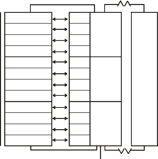
Figure 2.1 shows an example 3 logical responder MXP, which has a capability of 3 X 4 = 12
circuits (C1/1-1/4, C2/1-2/4, C3/1-3/4) and 12 relays (R1/1-1/4 ..... R3/4).
Splitting up the possible 200 addressable devices equally among the 12 circuits results in
each circuit being able to service 200/12 = 16 devices, with 8 left over. Thus devices 1-16
are associated with circuit C1/1, devices 17-32 are associated with C1/2, etc, up to C3/4,
which not only handles its own 16 points but also the extra 8 device addresses (193-200)
otherwise not catered for. Input devices are mapped to circuits, and output devices are
usually mapped to relays but may alternatively be mapped to the circuit.

MX4428 MXP Engineering / Technical Manual Document: LT0273
Responder Loop Design Considerations
Page 2-4 24 March 2006 Issue 1.5
Number of Logical
Responders
(NLR)
Number of Circuits (Relays)
available
(NC = 4 * NLR)
Number of Points per circuit
(relay)
PC = 200/NC
Total Quantity of Points
in Last Circuit
1
2
3
4
5
6
7
8
9
10
11
12
13
14
15
16
17
18
19
20
21
22
23
24
25
26
27
28
29
30
31
32
33
34
35
36
37
38
39
40
41
42
43
44
45
46
47
48
49
50
4
8
12
16
20
24
28
32
36
40
44
48
52
56
60
64
68
72
76
80
84
88
92
96
100
104
108
112
116
120
124
128
132
136
140
144
148
152
156
160
164
168
172
176
180
184
188
192
196
200
50
25
16
12
10
8
7
6
5
5
4
4
3
3
3
3
2
2
2
2
2
2
2
2
2
1
1
1
1
1
1
1
1
1
1
1
1
1
1
1
1
1
1
1
1
1
1
1
1
1
50
25
24
20
10
16
11
14
25
5
28
12
47
35
23
11
66
58
50
42
34
26
18
10
2
97
93
89
85
81
77
73
69
65
61
57
53
49
45
41
37
33
29
25
21
17
13
9
5
1
Table 2-1 Point Allocation For Various Numbers of Logical Responders
Document: LT0273 MX4428 MXP Engineering / Technical Manual
Responder Loop Design Considerations
Issue 1.5 24 March 2006 Page 2-5
MAPPED
TO
DEVICE 1-16
DEVICE 17-32
DEVICE 33-48
DEVICE 49-64
DEVICE 65-80
DEVICE 81-96
DEVICE 97-112
DEVICE 113-128
DEVICE 129-144
DEVICE 145-160
DEVICE 161-176
DEVICE 177-200
TOTAL OF
200 DEVICES
ANALOG LOOP
ANALOG LOOP
3 LOGICAL RESPONDER MXR
F4000 L
OOP
F4000 LOOP
C1/1 R1/1
C1/2 R1/2
C1/3 R1/3
C1/4 R1/4
C2/1 R2/1
C2/2 R2/2
C2/3 R2/3
C2/4 R2/4
C3/1 R3/1
C3/2 R3/2
C3/3 R3/3
C3/4 R3/4
LOGICAL
RESPONDER
#1
LOGICAL
RESPONDER
#2
LOGICAL
RESPONDER
#3
F4000
MASTER
Figure 2.1 Device To Circuit Mapping For 3 Logical Responder MXP
2.2.3 POINT TO CIRCUIT TO ZONE MAPPING
Taking the 3 logical responder example in the previous sections, assume that of the 16
possible device addresses that belong to C1/1, only 10 of these are in fact used, and that 7
are input devices, and the remaining 3 are output devices. Further, assume that the
MX4428 FIP is configured to map C1/1 to ZONE 1.
In this case, an alarm sensed by any of the 7 input devices would put C1/1 into alarm, which
in turn would put ZONE 1 into alarm, a condition indicated on the MX4428 Master front
panel. However, the MXP also generates what is referred to as an extended event,
indicating precisely which of the 7 input devices caused the alarm. This is transmitted to the
MX4428 Master where it is presented on the front panel LCD, entered in the history log and
printed on the logging printer (if programmed).
If, for instance, in this example it was input device 6 that caused the ALARM then the
extended event would take the form .....
"P1/6 ALARM" where .....
..... P = POINT
1 = BASE ADDRESS OF RESPONDER
6 = DEVICE NUMBER
If the Point Text expansion option is fitted at the MX4428 Master, the event will be
associated with a text description of the point.

MX4428 MXP Engineering / Technical Manual Document: LT0273
Responder Loop Design Considerations
Page 2-6 24 March 2006 Issue 1.5
So far only input devices have been considered. To continue our example for output
devices, if the MX4428 Master generated an output command, via output logic, to turn on
R1/1, then the MXP would activate all output devices associated with that relay, that is, in
this case, all 3.
2.3 IMPLICATIONS TO SYSTEM DESIGN
The System Designer should be aware of the following MX4428 characteristics before
proceeding with the design .....
(i) While the MX4428 with MXP capability can support up to 16 x 200 (3,200) points (i.e.
addressable devices), the Master unit has a maximum of 528 zones with which to
indicate the status of the system.
The 528 zones may be used to display the status of either an "alarm zone",
representing the status of a particular sub-section of the area to be monitored, or an
"ancillary control zone" (ACZ), representing the status of an output controlled by the
MX4428 system.
The Point Text expansion option can be used to extend this capability. Refer to the
F4000 Point Text Installation and Operation Manual (LT0228) for further information.
(ii) FIP zone indicators are controlled according to the zone’s status, which is generated
from the mapped circuit status. That is, the 4 circuits monitored by each of the 127
logical responders can control a maximum of 4 x 127 = 508 unique zones.
The point handling capability of an MX4428 system requiring individual LED
indicators per monitored point is therefore reduced to 508.
Therefore, the more individual LED indications that the FIP must show for each MXP
the more logical responders that MXP must represent.
Every additional 4 zones that must be indicated for the addressable devices on an
MXP incurs a cost of 1 additional logical responder (i.e. MX4428 responder loop
address).
(iii) For the same reasons as given in (ii) above, the more individually controllable output
devices the MXP must drive and control from logic, the more logical responders the
MXP must represent.

Document: LT0273 MX4428 MXP Engineering / Technical Manual
Device Information and Programming
Issue 1.5 24 March 2006 Page 3-1
CHAPTER 3
DEVICE INFORMATION AND PROGRAMMING
MX4428 MXP Engineering / Technical Manual Document: LT0273
Device Information and Programming
Page 3-2 24 March 2006 Issue 1.5
3.1 DEVICE TYPES
The MXP can communicate with a mix of up to 200 addressable devices, within limits
defined by loop size.
3.1.1 MX DEVICES
MX devices fall into three basic types:
(a) Sensors - Detectors (814PH, 814CH, 814I, 814H, VLC800)
(b) Ancillaries - Input (Monitor) (MIM800, MIM801, CIM800, DIM800)
- MCP (CP820, FP0838, FP0839)
- Output (Control) (RIM800, SNM800, LPS800)
(c) Bases - Standard Base (MUB, 5B)
- Short Circuit Isolator (5BI)
- Relay Base (814RB)
- Sounder Base (814SB, MkII Sounder Base)
In addition non-addressable smoke, thermal or flame detectors may be connected to the
MXP loop by means of the DIM800 Detector Input Module.
Code Description Input /
Output Remote
LED
814PH Photoelectric Smoke + Heat Detector I/O Y
814CH Carbon Monoxide + Heat Detector I/O Y
814I Ionisation Smoke Detector I/O Y
814H Heat Detector I/O Y
VLC800 Vesda Aspirating smoke detector I/O Y
MIM800 Mini Input Module Input
MIM801 Mini Input Module normally closed
interrupt (FP0837) Input
CP820 Manual Call Point Input
FP0838
FP0839 NZ Manual Call Point Input
CIM800 Contact Input Module Input
DIM800 Detector Input Module Input
RIM800 Relay Interface Module (unsupervised
load wiring) Output
SNM800 Sounder Notification Module (relay
output with supervised load wiring) Output
LPS800 Loop Powered Sounder Output
The devices above are addressed by the
801AP Service Tool
or by command from the diagnostics terminal of an MXP.

Document: LT0273 MX4428 MXP Engineering / Technical Manual
Device Information and Programming
Issue 1.5 24 March 2006 Page 3-3
The standard base for use with the 814 detectors is:
MUB Minerva Universal Base (4”)
5B Minerva Universal Base (5”)
The following special purpose bases may also be used.
5BI Isolator Base
814RB Relay Base
814SB Sounder Base
MkII Sounder Base
(802SB, 812SB, 901SB,
and 912SB)
Sounder Base
The 814RB and 814SB may be plugged into an MUB, 5B or a 5BI, or mounted directly on a
wall / ceiling.
Note that none of the bases are addressable devices. The functional bases (814RB, 814SB,
and MkII Sounder Base) are controlled by the MXP via the detector which is plugged into
them.
The devices above marked as “Input/Output” are always inputs, but may also be used as
outputs via the Remote Indicator output and the signal to the 814RB, 814SB, and MkII
Sounder Base functional bases. The output functionality is programmable and not
necessarily related to the input status.
The devices which have a remote LED output may drive a Tyco E500Mk2 remote LED. The
functionality of this LED is programmable and it does not necessarily follow the local LED.
A brief description of the capabilities of each device follows:
a) 814I Analogue Ionisation Smoke Detector
This unit uses an ionisation chamber (with a small radioactive source) to detect airborne
particles of combustion products.
b) 814H Analogue Heat Detector
This detector incorporates a temperature sensor. The temperature sensor processing may
be programmed as Type A (rate of rise plus fixed temperature = 63°C), Type B (fixed
temperature only = 63°C), Type C (rate of rise plus fixed temperature = 93°C), or Type D
(fixed temperature only = 93°C). Type A, B, C or D operation is programmable at the
MX4428 panel.
c) 814PH Analogue Photoelectric Smoke Detector + Heat Detector
This unit uses light scattering to detect airborne particles of combustion products, and in
addition incorporates a temperature sensor. The heat function may be programmed in the
same way as for the 814H detector.
d) 814P Analogue Photoelectric Smoke Detector
This unit uses light scattering to detect airborne particles of combustion products.
MX4428 MXP Engineering / Technical Manual Document: LT0273
Device Information and Programming
Page 3-4 24 March 2006 Issue 1.5
e) 814CH Analogue CO (Carbon monoxide) Detector + Heat Detector
This unit uses a special sensor to detect carbon monoxide, and in addition incorporates a
temperature sensor. The heat function may be programmed in the same way as for the
814H detector.
f) Mini Input Module MIM800
This unit has a single input for monitoring clean contacts (e.g. MCPs, flow switches
conventional detectors with hard contact outputs, relay contacts, switches). As well as
monitoring the state of the contacts the MIM800 can supervise the wiring for open circuit
fault and (optionally) short circuit fault.
g) Mini Input Module MIM801
This unit has a single input for monitoring clean contacts (e.g. MCPs, flow switches,
conventional detectors with hard contact outputs, relay contacts, switches). As well as
monitoring the state of the contacts the MIM801 can supervise the wiring for short circuit
fault and (optionally) open circuit fault. The MIM801 is very similar to the MIM800, however it
is optimised for normally closed applications and can generate an interrupt on an open
circuit. (Interrupt is only used when a fast response is required.) (The MIM800 and CIM800
can also generate interrupts, but only in response to closing contacts.)
h) Contact Input Module CIM800
This unit has two separate inputs for monitoring switch or relay contacts (e.g. MCPs, flow
switches, conventional detectors with hard contact outputs, relay contacts, switches). As well
as monitoring the state of the contacts the CIM800 can supervise the wiring for open circuit
fault and (optionally) short circuit fault. Although there are two separate inputs, both belong
to the same point. Either input in alarm will put the point into alarm, and either input in fault
will put the point into fault. Unused inputs must be terminated with a 200Ω resistor.
i) Detector Input Module DIM800
This unit has two separate inputs for monitoring conventional detectors. As well as
monitoring the state of the detectors they can supervise the wiring for open circuit faults.
Although there are two separate inputs, both belong to the same point. Either input in alarm
will put the point into alarm, and either input in fault will put the point into fault. An external
power supply is required. The voltage requirements for some conventional detector types
are very specific. (Refer to section 3.20).
j) Australian Call Point Module CP820
This unit consists of a MIM800 complete with a call point switch and break-glass housing.
k) New Zealand Call Point Module FP0838, FP0839
This unit consists of a MIM801 complete with a call point switch and break-glass housing.
FP0838 is flush mounting while FP0839 is surface mounting.
l) Relay Interface Module RIM800
This unit has voltage free changeover relay contacts rated at 2A 30Vdc for external loads.
No supervision of load wiring is provided. However the relay position is supervised and a
“relay checkback fail” fault will be generated if it does not operate.
Document: LT0273 MX4428 MXP Engineering / Technical Manual
Device Information and Programming
Issue 1.5 24 March 2006 Page 3-5
m) Sounder Notification Module SNM800
This unit has a relay rated at 2A 30Vdc for switching external loads. Supervision of load
wiring and the load supply is provided. The relay position is supervised and a “relay
checkback” fault will be generated if it does not operate.
n) Short Circuit Isolator 5BI
This detector base is designed for isolating short circuited sections of the analog loop. For
instance it can be used where the loop wiring crosses zone boundaries and it will prevent a
short circuit from affecting more than one zone. As well as housing a detector it can be used
with no detector inserted.
o) Sounder Base 814SB and MkII Sounder Base
These detector bases are designed as low cost warning devices. The MkII Sounder Base is
a newer version of the 814SB. Some variants are loop powered while others are powered by
an external supply. The sounder is controlled by the detector which is plugged into the base,
but the operation of the sounder can be quite separate from the operation of the detector.
The 814SB can be setup to generate a number of tones (none of which are AS2220 or
ISO8201 compliant), and three sound levels are selectable.
The MkII Sounder Base models can be setup to generate a number of tones including
AS2220 and ISO8201 compliant evacuation tones, and on some models the sound level is
continuously adjustable. Currently none of the MkII Sounder Base models are SSL listed.
Note that the current taken by a loop powered sounder base is very much higher than any of
the other loop devices (except the LPS800), and the number of sounder bases on a loop is
limited by the available current.
p) Relay Base 814RB
This detector base is designed for a low cost output device. It is controlled by the detector
which is plugged into it, but the operation of the relay can be quite separate from the
operation of the detector. A voltage two pole changeover relay is provided, rated at 1A 30V
dc.
q) Loop Powered Sounder LPS800
This device is similar to the SNM800, in that it drives one or more external sounders,
however the sounder power comes from the loop rather than an external power supply. The
available output current is much lower than that of a SNM800, and as all this current comes
from the loop, the number of LPS800s and their load is limited by the available loop current.
r) Vesda VLC800
The Vision Systems VLC800-MX VESDA Laser COMPACT is an aspirating smoke detector.
It samples the smoke from air which is extracted via piping from a large area of a building.
The sensitivity is adjustable over a wide range at the VLC800 by PC software programme.
The VLC800 requires a 24V power supply.
A summary of the electrical specifications of the various devices is shown in Table 3-1.

MX4428 MXP Engineering / Technical Manual Document: LT0273
Device Information and Programming
Page 3-6 24 March 2006 Issue 1.5
All loop devices are rated at a loop voltage of 20Vdc - 40Vdc and a signalling voltage of 2V
p-p – 6V p-p. Alarm Currents specified do not include remote indicators. Add 7mA for each
remote indicator.
DEVICE FUNCTION Comments
814I Ionisation Smoke Detector Requires base
814H Heat Detector Requires base
814PH Photo Smoke + Heat
Detector Requires base
814P Photo Smoke Detector Requires base
814CH CO + Heat Detector Requires base
MIM800 Mini Input Module EOL 200Ω
Alarm R (if used) 100Ω
Max Wiring R 10Ω
MIM801
Mini Input Module
(normally closed interrupt) N/O mode - as MIM800
N/C -
EOL 200Ω
Max wiring R 50Ω
CIM800 Contact Input Module EOL 200Ω
Alarm R (if used) 100Ω
Max Wiring R 10Ω
DIM800 (Conventional) Detector
Interface Monitor EOL 4k7
Requires separate supply.
CP820 Call Point
FP0838, FP0839 NZ Call Point
RIM800 Relay Interface Module 2A 30Vdc
SNM800 Sounder Notification
Module (Supervised relay
output)
2A 30Vdc.
Requires external supply.
LPS800 Loop Powered Sounder
Module Provides 24V at up to 75mA
MUB Standard Base
5BI Isolator Base
814SB Loop Powered Sounder
Base Selectable tone (not AS2220 or ISO8201)
Adjustable sound level
802SB Loop Powered Sounder
Base Selectable tone (Including AS2220 and ISO
8201 Evacuation tone)
Adjustable sound level
812SB Loop Powered Sounder
Base Selectable tone (Including AS2220 and ISO
8201 Evacuation tone)
901SB
Externally Powered
Sounder Base Selectable tone (Including AS2220 and ISO
8201 Evacuation tone)
Adjustable Sound Level.
Requires external 24V
MkII
Sounder
Bases
912SB Externally Powered
Sounder Base Selectable tone (Including AS2220 and ISO
8201 Evacuation tone)
Requires external 24V
814RB Relay Base 1A 30Vdc
2 pole changeover
VLC800 Vesda aspirating smoke
detector Requires external supply. Requires PC to
set up.
Table 3-1 Compatible Device Summary
The MXP will allow some alternative devices to be used without generating a fault, where the
inserted device can provide all the features of the configured device. This includes an 814PH
or 814CH used where an 814H was programmed, a CIM800 used where a MIM800 was
programmed, and an 814PH used where an 814P was programmed.

Document: LT0273 MX4428 MXP Engineering / Technical Manual
Device Information and Programming
Issue 1.5 24 March 2006 Page 3-7
3.2 DEVICE HANDLING CAPABILITY
3.2.1 OVERVIEW
The parameters which determine the maximum number of each device type that can be put
on a loop are as follows. The column “MAX NO. DEVICES” assumes that all devices are of
the same type. If this is not the case, it is necessary to perform the calculations described
below.
DEVICE MAX NO.
DEVICES
Quiescent
Current Alarm
Current AC Units
(max 250
total)
IB Units
(max 100 IB
units between
Isolator Bases)
814I 200 330uA 3.0mA 1 1.4
814H 200 250uA 3.0mA 1 1
814PH 200 275uA 3.0mA 1 1.2
814P 200 275uA 3.0mA 1 1.2
814CH 200 275uA 3.0mA 1 1
MIM800 200 275uA 2.8mA (with LED)
275uA (no LED) 1 1.5
MIM801 200 275uA 2.8mA (with LED)
275uA (no LED) 1 1.5
CIM800 200 275uA 2.8mA 1 1
DIM800 200 100uA
(Loop) 100uA (Loop) 1 1
CP820 200 275uA 2.8mA 1 1.5
RIM800 200 285uA 2.8mA (with LED)
285uA (no LED) 1 5
SNM800 200 450uA 3.0mA (with LED)
450uA (no LED) 1 5
LPS800 33 or less,
depends on
load
450uA Load current +
4mA, with
minimum of 12mA
1.5 1
5BI N/A 80uA 0.2 N/A
814SB 40(Quiet)
30(Medium)
24(Loud)
400uA 9mA(Quiet)
12mA(Medium)
15mA(Loud)
2.4 2.5
802SB* 200(Quiet)
50 (Loud) 200uA 1.2mA (Quiet)
6.8mA (Loud) 0.5 2.5
812SB* 18 200uA 21mA 0.5 2.5
901SB* 200 200uA 200uA (Loop) 0.5 2.5
912SB* 200 200uA 200uA( Loop) 0.5 2.5
814RB 200 50uA 100uA 0.3 1.6
VLC800 125 300uA 300uA (no LED)
2.8mA (with LED) 2 1
*Models of MkII Sounder Base
Table 3-2 Device Quantities and Loading
The particular combination of device types, external loads, cable length and type may limit
the total number of devices. This is calculated in the following sections.
There are two types of load which must be considered - DC and AC. Also if isolator bases
are used, the loading between each isolator base must be considered.

MX4428 MXP Engineering / Technical Manual Document: LT0273
Device Information and Programming
Page 3-8 24 March 2006 Issue 1.5
It is recommended that the PC program F4000CAL is used for conducting the loop loading
calculations. However note that it does not include the isolator base loading, this must be
done manually.
3.2.2 DC LOAD
The total current available from the MX Loop terminals on the MXP is 400mA DC.
This must supply operating current to all addressable devices an the loop. This not only
includes the quiescent current required to power the device electronics, but also the
additional current drawn by devices in the ALARM state or by associated ALARM LEDs and
other loop powered outputs.
The sum of currents for all devices connected to the loop is calculated using the “alarm
current” values shown in Table 3-2. Note –
1) The MXP limits the number of Alarm LEDs turned on at any one time to 5
(programmable at MX4428).
2) Remote LEDs must be allowed for at 7mA each. Remote LEDs programmed to follow
the detector LED will be limited by the number of alarm LEDs. However remote LEDs
programmed to operate on “Circuit Alarm” or “Relay” will not be limited in any way.
3) LEDs on relay output devices (SNM800, RIM800, LPS800) will operate when the
relay is activated, if the MXP is configured at the MX4428 to flash the LED on Poll
“Global Blink Mode”.
4) The 814RB, RIM800 and SNM800 relay load current must not be supplied from the
analogue loop.
The sum of all currents must not exceed 400mA.
Furthermore, the voltage drop in the cable must not exceed 16.0V, regardless of which end
of the loop the cable is driven from. This is in order to ensure that with the minimum 36V
voltage available from the MX Loop terminals on the MXP, the minimum voltage at any
device will be at least 20V.
If you have any LPS800 devices on the loop, you may need to design for a higher minimum
loop voltage and a lower voltage drop. Refer to section 3.23.2.
3.2.3 AC LOADING
Calculate the total of the “AC Units” shown in Table 3-2. The total must not exceed 250.
Also ensure that the cable length does not exceed the values in Table 3-3.
Cable type Cable length
MICC 2L1.5, 2L2.5, 1H1.5, 2H2.5 1.8 km*
Steel Wire Armour (SWA) 1.8 km*
Fire resistant ‘foil and drain wire’, e.g.
Radox FR3013, FP200, Lifeline, Firetuff 2 km
BS6883 marine cable 2 km
Table 3-3 Maximum Cable Lengths
* Up to 2km of these cable types may be used on condition that the maximum AC loading is
restricted to less than 220 AC units per loop.
Document: LT0273 MX4428 MXP Engineering / Technical Manual
Device Information and Programming
Issue 1.5 24 March 2006 Page 3-9
3.2.4 ISOLATOR BASE LOADING
If isolator bases are being used, calculate the sum of the “IB Units” from Table 3-2 for each
section of cable between isolator bases (or between the last isolator base and the end of a
cable spur). Include only one of the detectors at the ends of the section. The sum for any
section must not exceed 100.
See also section 4.1.3 for details of AS1670 requirements and section 4.1.4 for details of
NZS4512 requirements.
3.2.5 EXAMPLE
Consider an MXP monitoring 200 * 814PH detectors with 10 814SB Sounder Bases set to
High, on a 1300 metre long loop, using 1.5mm2 wire. The cable is divided (with 9 Isolator
Bases) into 10 segments with 1 Sounder Base and 20 detectors on each segment.
(i) Calculate DC Load
IA = 195 x 275uA (No. of detectors in NORMAL)
+ 5 x 3.0mA (No. of detectors with Alarm LEDs turned on, assume limited to
5 max by MXP)
+ 10 x 15mA (Number of 814SB Sounder Bases)
+ 9 x 80uA (Number of Isolator Bases)
(Ref
Table 3-2. Note 1mA = 1000uA)
= 220mA which is well under 400mA
For the voltage drop calculation, assume the worst case in the first instance, i.e. that
all devices are at the far end of 1300 metres. The loop resistance of 1.5mm2 wire is
25Ω per 1000m and the isolator base resistance is 0.25Ω.
Total R = 25Ω x 1.3 + 9 x 0.25Ω
= 34.75Ω.
Voltage drop = 34.75 x 0.220 = 7.7V, which is well under the maximum allowable of
16V.
(ii) Calculate AC Load
AC Units = 200 x 1 (detectors)
+ 10 x 2.4 (Sounder Bases)
+ 10 x 0.1 (Isolator Bases)
= 225 which is less than the maximum allowable of 250.
Cable length is well under the limits specified in Table 3-3.
(iii) Calculate IB Load
IB Units for each section = 20 * 1.2 (814PH) + 1 * 2.5 (814SB)
= 26.5 which is less than 100.
As all parameters are within the specified limits, the design is satisfactory.

MX4428 MXP Engineering / Technical Manual Document: LT0273
Device Information and Programming
Page 3-10 24 March 2006 Issue 1.5
3.3 OUTPUT CONTROL
The following “outputs” are available on the Analogue loop –
• Output modules – RIM800, SNM800, and LPS800
• Functional Base outputs of detectors (controlling 814SB, MkII Sounder Base or 814RB)
• Remote LED output of detectors.
Each of these is programmable at the MX4428 for which of 3 sources controls the output.
In all cases the outputs are turned off if the point is isolated.
The 3 selectable sources are as follows –
1. Relay output
The output is controlled by the state of the corresponding relay output as sent to the
responder. The relay output state can be controlled directly with a logic equation, be
controlled by the state of the ACZ that the relay is mapped to (this also allows supervision
fault states on the SNM800 and LPS800 output to be indicated), or be controlled by the test
state of the flow switch zone it is mapped to.
The functional bases and remote LED outputs for detectors mapped to circuit X of logical
responder R will be controlled by the state of relay X of logical responder R, i.e. the relay
with the same number as the detector circuit.
2. Circuit alarm
The output will turn on when the corresponding circuit goes into alarm. If the circuit maps to
a latching zone then the output will turn off when the zone alarm is reset. If the circuit does
not map to a latching zone the output will turn off when the circuit goes out of alarm. The
circuit alarm state is determined by the MXP and so can’t include other responder circuits,
nor the state of the zone(s) the circuit maps to. (Use “relay output” if these are needed.)
The functional bases and remote LED outputs for detectors will be controlled by the circuit
the detector is mapped to. Output modules mapped to relay X of logical responder R will be
controlled by circuit X of logical responder R, i.e. the circuit with the same number as the
relay.
WARNING - the output will not be disabled by zone isolate.
3. Point alarm
The output will turn on when that point goes into alarm. If the point maps to a latching zone
then the output will stay on until the zone alarm is reset. If the point does not map to a
latching zone the output will turn off when the point goes out of alarm.
This option is not available on output modules (RIM800, SNM800, and LPS800).
WARNING - the output will not be disabled by zone isolate.

Document: LT0273 MX4428 MXP Engineering / Technical Manual
Device Information and Programming
Issue 1.5 24 March 2006 Page 3-11
3.3.1 PROGRAMMING
The programming of the output functions is done by setting the “mode” value for the RIM800,
SNM800, and 814I, and by one of the 7 device parameters for the 814H, 814PH, and
814CH. The LPS800 is programmed as an SNM800.
For example the following are the settings for the 814I.
Mode Functional Base Control Remote LED Control
0 Circuit Alarm Circuit Alarm
1 Circuit Alarm Relay
2 Circuit Alarm Point Alarm
4 Relay Circuit Alarm
5 Relay Relay
6 Relay Point Alarm
8 Point Alarm Circuit Alarm
9 Point Alarm Relay
10 Point Alarm Point Alarm
The value must be chosen from the above table to give the desired settings for controlling
the functional base and the remote LED.
For the 814PH and 814CH, programming of the “enhancement multiplier” is included in the
same parameter. The desired enhancement multiplier must be multiplied by 16 and the
result added to the above numbers. The tables in the sections for these detectors (3.9.3 and
3.10.3) include the result when the default enhancement multiplier is used.
For the 814H detector and for an 814PH or 814CH with enhancement disabled, the
“enhancement multiplier” is irrelevant and therefore the above numbers may be entered
directly if desired. The global defaults for parameter 6 for all these detector types should
always include the desired enhancement multiplier * 16.
For the SNM800, other options are also included in the mode. Refer to section 3.22.4 for
details.
3.3.2 OUTPUT STATE UNDER EXCEPTIONAL CIRCUMSTANCES
All outputs retain their state if the MX4428 stops polling the responder (e.g. processing is
stopped), or if the MXP stops polling the devices (e.g. due to a new configuration download
from the MX4428). If a detector is removed from a relay or sounder base, the relay or
sounder output turns off.
If power to the MXP is lost, loop powered sounder bases turn off. RIM800 and SNM800
outputs, relay bases and possibly externally powered sounder bases usually retain their
state until MXP power is restored, then turn off when polling resumes (which may take some
minutes if the MXP has been off for some hours and lost its configuration), then revert to ON
after a few seconds if this is the correct state.

MX4428 MXP Engineering / Technical Manual Document: LT0273
Device Information and Programming
Page 3-12 24 March 2006 Issue 1.5
3.4 DETECTOR PARAMETER SETTINGS SUMMARY
The following table gives a summary of the MX4428 default and alternate settings, and
approved range, for each detector type.
Detector Default Alternate Range Comments
814PH
Smoke 12%
(80 det units) 8%
(37 det units) 8% - 12% Enhancement is optional,
default off.
814PH
Smoke
FastLogic
Medium N/A Low, Medium,
High (all
approved with
nominal
sensitivity =
8%)
Enhancement is optional,
default off.
814PH Heat
component 63 N/A 60 - 65 Type B default.
Type A is option
Off is option.
814CH
CO 38ppm
(0.3 MIC X)
(93 det units)
66ppm(1)
(0.6 MIC X)
(160 det units)
23 - 66ppm(1)
Enhancement is optional,
default off.
(23ppm = 0.15 MIC X
= 60 det units)
814CH Heat
component 63 N/A 60 - 65 Type A default.
Type B is option
Off is option.
814I 0.39 MIC X
(66 det units) 0.22 MIC X
(23 det units) 0.2 - 0.4 (Aus)
0.2 - 0.6 (NZ) 0.59 MIC X =130 det
units
814H 63 N/A 60 - 93 (Aus)
50 - 80 (NZ) Type A default. Type B
option.
Types C/D by changing
temperature to 93.
VLC800 Fixed at 100 0.005% / m to
20% / m Note that actual
sensitivity is adjusted by
PC connected to the
VLC800.
(1) 66ppm is outside the approved range of the 814CH as an ionisation detector. However it
is an accepted value as a CO detector.
Prealarm
The Prealarm default and alternate sensitivities will generally be about 70% - 80% of the
corresponding alarm level. Note that Prealarm will also be more sensitive to rapidly changing
conditions as it does not go through the step limiting filter.
Conversion
Det Units = Detector Units.
Temperatures are already converted by the MXP to degrees C and do not require
conversion.

Document: LT0273 MX4428 MXP Engineering / Technical Manual
Device Information and Programming
Issue 1.5 24 March 2006 Page 3-13
Conversion from detector units to displayed values is by imagining a graph with a series of
joined straight lines from (0,0) and passing through each of the above defined points (e.g.
814PH 37 det units = 8%) and extrapolated in a continuing straight line past the highest
point if necessary.
For the 814PH detector the displayed values bear little resemblance to the static sensitivity
of the detector. They are valid only for the tests done in the SSL smoke room.
3.5 DEVICE INSTALLATION
3.5.1 PRECAUTIONS
Observe ESD precautions when installing an MXP responder, or connecting any devices to
it. Refer to Product Bulletin PBG0025.
3.5.2 MOUNTING
Detector Bases
Detectors attach to a circular, plastic base which has holes for screw mounting to a flat
surface, and screw terminals for connecting the loop wiring. There are various different
bases available. Most of the bases may only be mounted as just described, but the 814SB
sounder base and the 814RB relay base may be mounted as just described, or may
themselves be plugged into one of the other bases, to interpose between it and the detector.
Modules
The Modules are normally mounted within the enclosure of the equipment to which they
connect, or in a cabinet, junction box or switch box. They may be mounted on plastic
standoffs (4 x HW0130 required) on a gearplate or cabinet, or to a face plate that mounts on
a double flush or surface box. A hole may be required for the on-board LED. A standard
plate with a hole for the LED and three holes for the Service Tool is available (Ancillary
Cover M520). This fits a plastic surface box K2142.
The MIM800/801 is smaller than the other modules, and is supplied in a plastic housing
which has a lug for screw mounting.
3.5.3 ADDRESS & LED BLINK PROGRAMMING
Addresses for MX detectors and modules, and options such as LED blink on poll, are most
easily set using the MX Service Tool. These are set by placing the detector onto the Service
Tool, or connecting the module to the Service Tool with the supplied interface lead, and
programming as per the MX Service Tool Instructions. (Be careful not to leave the pins in the
module when removing the lead).
For all input devices, including detectors, the LED turns on steady when in alarm. For output
devices (RIM800, etc) the LED turns on when the device is activated (if Global Blink Mode is
enabled for the MXP). To enable a device’s LED to blink on poll, the MXP must have Global
Blink Mode enabled at the MX4428 panel, and the device must have LED Blink enabled.
For a mixed system, i.e. some devices are to blink on poll and some are not, then turn off
blink on those devices that are not to blink using the Service Tool, and enable Global Blink
Mode at the MX4428 panel for the MXP.

MX4428 MXP Engineering / Technical Manual Document: LT0273
Device Information and Programming
Page 3-14 24 March 2006 Issue 1.5
3.6 MX4428 PROGRAMMING
In the following sections information is given about the programming of each device in the
MX4428. An explanation of the mode and the various parameters is given for each device
type, along with the global parameters that affect that device type. It is critical that only the
listed mode values are used for each device type, as in many cases the mode value is used
to define the actual device type. An incorrect mode value may cause a POINT TYPE
MISMATCH to be generated, or it may just render a device not able to work.
In some of the following sections descriptions are given about changing the sensitivity for a
detector by altering the specific parameter for that detector. This is correct (it sets the value
for just that individual detector), but in many cases it may be better to adjust the global
sensitivity for that device type so that all detectors of that type take on the new value. For
example, in NZ mode it is recommended that the global heat alarm temperature be set to
57°C for both 814PH and 814CH, rather than setting each specific detector to this value.
Details for NZ mode settings are contained in the F4000 NZ Technical Manual (LT0126).
These details are most relevant when programming the MX4428 from a (dumb)
programming terminal. Alternatively you can program with "SmartConfig", which displays
and edits functional parameters and takes care of mapping the functional parameters into
the appropriate mode and parameter bytes for each device type.

Document: LT0273 MX4428 MXP Engineering / Technical Manual
Device Information and Programming
Issue 1.5 24 March 2006 Page 3-15
3.7 814H HEAT DETECTOR
3.7.1 GENERAL
The 814H is an analogue thermal detector. The detector senses the air temperature and
sends this value to the MXP. The MXP makes any decisions as to whether this is an alarm,
fault, normal or whatever. The MXP can be programmed (at the MX4428 panel) to interpret
the values to implement a Type A, Type B, Type C, or Type D Heat Detector. The integral
LED is turned on by the MXP when an alarm is detected.
The 814H has a temperature sensing range of -25°C to 95°C. The approved operating
temperature range is -10°C to +70°C. The accuracy of the 814H (as interpreted by the
MXP), within the range 0°C to 70°C, is typically + / - 2°C.
The remote LED and functional base outputs are programmable for their functionality (refer
to section 3.3).
3.7.2 814H SPECIFICATIONS
Line Connections L(–), L1(+)
Supply Voltage: 20Vdc - 40Vdc
Supply Current: 250uA (typical quiescent)
Alarm Current: 3.0mA (typical)
Remote LED Current: 7mA (Tyco E500Mk2)
Dimensions: 110mm (diameter) x 55mm (including MUB base)
Weight 79g
Base MUB, 5B, 5BI, 814RB, 814SB, or MkII Sounder Base
3.7.3 MX4428 PROGRAMMING OPTIONS - 814H
The programming values for the 814H are described in the following tables.
“Mode” enables or disables rate of rise processing. Mode = 4 selects type A/C (heat rate of
rise enabled), and mode = 5 selects type B/D (heat rate of rise disabled). Only select one of
these two values. (Note that when rate of rise is disabled, the parameters relating to rate of
rise are ignored - there is no need to adjust them.)
For type C and D operation set the heat fixed temperature alarm threshold (Parameter 1) to
93 (°C).
Parameter 0 may be adjusted to select a different Pre-Alarm temperature.
For special purposes, the fixed temperature alarm threshold may be set to any value
between 60 and 93 for Australia, and between 50 and 80 for New Zealand. In New Zealand
also set the global parameter “8XX HEAT SL1” to (the highest alarm temperature - 20) / 10
(rounded up if the result is fractional).
For functional base and remote LED programming set Parameter 6 as per the table. Refer
to section 3.3 for further details.
The remaining parameters should not need changing.

MX4428 MXP Engineering / Technical Manual Document: LT0273
Device Information and Programming
Page 3-16 24 March 2006 Issue 1.5
Parameter Description Default
Value Heat Type
4 A/C – rate of rise enabled.
Mode
5 B/D – rate of rise disabled
4
P0 Heat fixed temperature pre-alarm threshold °C 56 (°C)
Heat fixed temperature alarm threshold °C
57 New Zealand
63 Australian Types A / B
P1
93 Australian Types C / D
63 (°C)
b3:b0 ROR Pre alarm Threshold 7 (12°C/min)
P4
b7:b4 ROR Alarm Threshold
Number + 5 gives the
Threshold in °C/min 9 (14°C/min)
P5
Enhancement multiplier (default 12) * 16 plus code below
Code Functional Base
Control Remote LED
Control Final value
with default
enh multiplier
0 Circuit Alarm Circuit Alarm 192
1 Circuit Alarm Relay 193
2 Circuit Alarm Point Alarm 194
4 Relay Circuit Alarm 196
5 Relay Relay 197
6 Relay Point Alarm 198
8 Point Alarm Circuit Alarm 200
9 Point Alarm Relay 201
P6
10 Point Alarm Point Alarm 202
192
Note – enhancement multiplier is unused for individual 814H detector settings, but must be
retained in MX4428 default settings, as the same defaults are used for the 814H and
814PH.
The following global parameters, which may be set at the MX4428, affect all applicable
points on all MXPs.
MX4428 Reference Description Default
8XX HEAT FD1 Heat FD1 (CV Filter) 4
8XX HEAT FD2 Heat FD2 (ROR determination) 7
8XX HEAT SL1 Heat SL1 (Fixed temp step limit, °C/5sec) 2
8XX HEAT SL2 Heat SL2 (ROR step limit, °C/min/5sec) 3

Document: LT0273 MX4428 MXP Engineering / Technical Manual
Device Information and Programming
Issue 1.5 24 March 2006 Page 3-17
3.8 814I IONISATION SMOKE DETECTOR
3.8.1 GENERAL
The 814I is an ionisation smoke detector. The detector senses the amount of smoke present
and sends this value to the MXP. The MXP makes any decisions as to whether this is an
alarm, fault, normal or whatever. The integral LED is turned on by the MXP when an alarm is
detected.
The remote LED and functional base outputs are programmable for their functionality (refer
to section 3.3).
3.8.2 814I SPECIFICATIONS
Line Connections L(–), L1(+)
Supply Voltage 20Vdc - 40Vdc
Supply Current 330uA (typical quiescent)
Alarm Current 3.0mA (typical)
Remote LED Current 7mA (Tyco E500Mk2)
Dimensions 110mm (diameter) x 55mm (including MUB base)
Weight 81g
Base MUB, 5B, 5BI, 814RB, 814SB, or MkII Sounder Base
3.8.3 MX4428 PROGRAMMING OPTIONS - 814I
The programmable values for the 814I are explained in the following table.
Normally only the mode needs to be programmed, and then only if a functional base or
remote LED is required and its operation is different from the default. Refer to section 3.3.
In some cases the alarm sensitivity (Parameter 1) may need to be changed from the default.
The approved range for Australia is 0.22 MIC X (23) to 0.39 MIC X ( 66). The available range
is 0.22 MIC X (23) to 0.59 MIC X (130). If the alarm sensitivity is changed, the pre-alarm
sensitivity (Parameter 0) should normally be changed to about 75% of the alarm sensitivity.
The remaining parameters should not need changing.

MX4428 MXP Engineering / Technical Manual Document: LT0273
Device Information and Programming
Page 3-18 24 March 2006 Issue 1.5
Parameter Description Default
Value Functional Base Control Remote LED Control
0 Circuit Alarm Circuit Alarm
1 Circuit Alarm Relay
2 Circuit Alarm Point Alarm
4 Relay Circuit Alarm
5 Relay Relay
6 Relay Point Alarm
8 Point Alarm Circuit Alarm
9 Point Alarm Relay
Mode
10 Point Alarm Point Alarm
0
P0 Pre Alarm Threshold 50
Alarm Threshold
Value Threshold
23 0.22 MICX (Alternate)
66 0.39 MICX (Default)
P1
130 0.59 MICX
66
P2 Fault Limit (i.e. values below this are assumed to indicate a
detector fault) 10
P3 Dirty Alert Limit (i.e. a “dirty alert” will be raised if the
tracked “clean air” value reaches this limit) 120
b3:b0 Filter Divisor 3 P4 b7:b4 Step Limit 5
P5 Tracking Interval i.e. the interval at which the tracked “clean
air” value is adjusted. 30 (minutes)
P6 Tracking adjustment - fixed at 1 in MXP 1
The following global parameters which may be set at the MX4428 affect all applicable points
on all MXPs.
MX4428 Reference Description Default
8XXI UPPER
TRACKING LIMIT Ionisation Upper Tracking Limit
(i.e. the maximum assumed value for
clean air)
120 (MXP
Default)

Document: LT0273 MX4428 MXP Engineering / Technical Manual
Device Information and Programming
Issue 1.5 24 March 2006 Page 3-19
3.9 814PH PHOTOELECTRIC SMOKE & HEAT
DETECTOR & 814P PHOTOELECTRIC SMOKE
ONLY DETECTOR
3.9.1 GENERAL
The 814PH is a photoelectric smoke detector which also includes a temperature sensor. The
detector senses the amount of smoke present and the temperature and sends these values
to the MXP. The MXP makes any decisions as to whether this is an alarm, fault, normal or
whatever, based on the smoke level, temperature, or rate of rise of temperature, and/or a
combination of these. The integral LED is turned on by the MXP when an alarm is detected.
Refer to the specifications of the 814H for more details on the heat sensing element of the
814PH.
The 814P is the same as the 814PH, except that it has no temperature sensor.
The remote LED and functional base outputs are programmable for their functionality (refer
to section 3.3).
3.9.2 814PH & 814P SPECIFICATIONS
Line Connections L(–), L1(+)
Supply Voltage 20Vdc - 40Vdc
Supply Current 275uA (typical quiescent)
Alarm Current 3.0mA (typical)
Remote LED Current 7mA (Tyco E500Mk2)
Dimensions 110mm (diameter) x 55mm (including MUB base)
Weight 76g
Base MUB, 5B, 5BI, 814RB, 814SB, or MkII Sounder Base
3.9.3 MX4428 PROGRAMMING OPTIONS - 814PH/814P
In the MX4428 programming there are two different device types that use the 814PH/814P
detector. Type 16 814PH is used when the 814PH is used with the SmartSense algorithm
and type 27 814PHFL is used when the FastLogic algorithm is required. These different
device types allow the MX4428 to have separate sensitivity settings for the algorithms and
for the sensitivities to be displayed correctly.
However, the mode value actually defines to the MXP which algorithm is to be used.
Mode values 0 – 7 must only be used with a device type of 814PH, and mode values 8 – 15
must only be used with a device type of 814PHFL. Do not use an incorrect mode, as the
values displayed at the MX4428 will not match those being used or generated at the MXP.
The 814P must be programmed as an 814PH, with no heat. I.e. only modes 7 and 13 are
allowed. The MX4428 will display the point type as 814PH.
The programmable values for the 814PH and 814P are described in the following tables.
MX4428 MXP Engineering / Technical Manual Document: LT0273
Device Information and Programming
Page 3-20 24 March 2006 Issue 1.5
The mode selects the detection mode for the detector - smoke only, enhanced smoke, heat
enabled or disabled, heat rate of rise enabled or disabled, smoke detection algorithm is
SmartSense or FastLogic, etc. Note that when a particular function is disabled by the setting
of the mode, the parameters relating to that function are not used and should therefore be
left with their default settings.
Parameter 1 selects the smoke alarm threshold.
With the SmartSense algorithm, the actual alarm threshold is selected as per the table. The
approved range is 8%/m (Parameter 1 = 37) to 12%/m (Parameter 1 = 80).
With the FastLogic algorithm Parameter 1 values of 0, 1, or 2 will select Low, Medium, or
High sensitivity respectively. Any other value will select the sensitivity defined in the global
parameter 8XXPH FUZZY ALGORITHM. Parameter 1 can usually be left at its default
setting for all detectors and those detectors with their mode set to FastLogic will then use the
setting in the global parameter 8XXPH FUZZY ALGORITHM. All three FastLogic sensitivities
are SSL approved and all have a nominal sensitivity of 8% / m.
Parameter 3 may be adjusted to vary the fixed temperature alarm threshold. It may be set to
any value between 60 and 65 in Australia, and between 50 and 65 in New Zealand.
Parameter 2 may be adjusted to select a different Pre-Alarm temperature.
Parameter 6 selects the functional base and remote LED output operation (refer to section
3.3) and the “enhancement multiplier” which should normally be left at the default value (12).
The remaining parameters should not need changing.

Document: LT0273 MX4428 MXP Engineering / Technical Manual
Device Information and Programming
Issue 1.5 24 March 2006 Page 3-21
Parameter Description Default
Value Smoke
Algorithm Enhance smoke
sensitivity with
heat Rate of
Rise.
Heat Type
A – rate of rise
enabled
B – rate of rise
disabled
0 SmartSense Yes A
1 SmartSense Yes B
2 SmartSense No A
3 SmartSense No B
4 None A
5 None B
6 SmartSense Yes No heat alarm
7 SmartSense No No heat alarm *
8 FastLogic Yes A
9 FastLogic Yes B
10 FastLogic No A
11 FastLogic No B
12 FastLogic Yes No heat alarm
Mode
13 FastLogic No No heat alarm *
3
P0 SmartSense smoke Pre Alarm Threshold 68
SmartSense smoke Alarm Threshold
Value Threshold
37 8% / m (alternate)
80 12% / m (default)
FastLogic Sensitivity
Value Sensitivity
0 Low
1 Medium
2 High
P1
Any other Global Parameter
“8XXPH Fuzzy Algorithm”
80
P2 Heat fixed temperature pre-alarm threshold °C 56 (°C)
Heat fixed temperature alarm threshold °C
Value Usage
57 New Zealand
P3
63 Australian Types A / B
63 (°C)
b3:b0 ROR Pre alarm Threshold 7 (12°C/min)
P4
b7:b4 ROR Alarm Threshold
Number + 5 gives the
Threshold in °C/min 9 (14°C/min)
b3:b0 Smoke Filter Divisor 3 P5 b7:b4 Smoke Step Limit 4
Enhancement multiplier (default 12) * 16 plus value below
Value Functional Base
Control Remote LED
Control Result with
default enh
multiplier
0 Circuit Alarm Circuit Alarm 192
1 Circuit Alarm Relay 193
2 Circuit Alarm Point Alarm 194
4 Relay Circuit Alarm 196
5 Relay Relay 197
6 Relay Point Alarm 198
8 Point Alarm Circuit Alarm 200
9 Point Alarm Relay 201
P6
10 Point Alarm Point Alarm 202
192
* These are the only modes allowed with the 814P detector.

MX4428 MXP Engineering / Technical Manual Document: LT0273
Device Information and Programming
Page 3-22 24 March 2006 Issue 1.5
The following global parameters which may be set at the MX4428 affect all applicable points
on all MXPs.
MX4428 Reference Description Default
8XXPH UPPER
TRACKING LIMIT Photo Upper Tracking Limit (i.e. the
maximum assumed value for clean
air)
56 (MXP Default)
8XXPH DIRTY
ALERT LIMIT Photo Dirty Alert Limit (i.e. a “dirty
alert” will be raised if the tracked
“clean air” value reaches this limit)
56
8XXPH TRACK
INTERVAL Photo Tracking Interval
i.e. the interval at which the tracked
“clean air” value is adjusted.
30 (minutes)
8XXPH FUZZY
ALGORITHM Fuzzy Sensitivity if Device Parameter
1 is not 0, 1, or 2
0 = low
1 = medium
2 = high
1 (medium)
(MXP also chooses
Medium if this
parameter is not 0,
1, or 2)

Document: LT0273 MX4428 MXP Engineering / Technical Manual
Device Information and Programming
Issue 1.5 24 March 2006 Page 3-23
3.10 814CH CARBON MONOXIDE + HEAT DETECTOR
3.10.1 GENERAL
The 814CH is a carbon monoxide (CO) detector which also includes a temperature sensor.
The detector senses the amount of CO present and the temperature and sends these values
to the MXP. The MXP makes any decisions as to whether this is an alarm, fault, normal or
whatever, based on the CO level, temperature, or rate of rise of temperature, and/or a
combination of these. The integral LED is turned on by the MXP when an alarm is detected.
Refer to the specifications of the 814H for more details on the heat sensing element of the
814CH.
The remote LED and functional base outputs are programmable for their functionality (refer
to section 3.3).
3.10.2 814CH SPECIFICATIONS
Line Connections L(–), L1(+)
Supply Voltage 20Vdc - 40Vdc
Supply Current 275uA (typical quiescent)
Alarm Current 3.0mA (typical)
Remote LED Current 7mA (typical Tyco E500Mk2)
Dimensions 110mm (diameter) x 55mm (including MUB base)
Weight 88g
Base MUB, 5B, 5BI, 814RB, 814SB, or MkII Sounder Base
3.10.3 MX4428 PROGRAMMING OPTIONS - 814CH
The programmable values for the 814CH are described in the following tables.
The mode selects the detection mode for the detector - CO only, enhanced CO, heat
enabled or disabled, heat rate of rise enabled or disabled, etc. Note that when a particular
function is disabled by the setting of the mode, the parameters relating to that function are
not used and should therefore be left with their default settings.
Parameter 1 selects the CO alarm threshold. Some possible settings are shown in the table.
Note the alternate setting of 66ppm is not an SSL listed setting for an ionisation detector (the
814CH was SSL tested using the tests for an ionisation detector under AS1603.2, as at the
time there was no approved standard for CO detector). Although this setting is acceptable
for a CO detector it should only be used for special applications where installation conditions
exclude other smoke detectors and yet the background CO level may be higher than normal.
At this sensitivity the background CO level should not exceed 30ppm.
Parameter 3 may be adjusted to vary the fixed temperature alarm threshold. It may be set to
any value between 60 and 65 in Australia.
Parameter 2 may be adjusted to select a different Pre-Alarm temperature.
Parameter 6 selects the functional base and remote LED output operation (refer to section
3.3) and the “enhancement multiplier” which should normally be left at the default value (12).

MX4428 MXP Engineering / Technical Manual Document: LT0273
Device Information and Programming
Page 3-24 24 March 2006 Issue 1.5
The remaining parameters should not need changing.
Parameter Description Default
Value Enhance CO
sensitivity with heat
Rate of Rise
Heat Type
A – rate of rise enabled
B – rate of rise disabled
0 Yes A
1 Yes B
2 No A
3 No B
6 Yes No heat alarm
Mode
7 No No heat alarm
2
P0 CO Pre Alarm Threshold 80
CO Alarm Threshold
Value Threshold
60 23ppm
93 38ppm (default)
P1
160 66ppm (alternate)
93
P2 Heat fixed temperature pre-alarm threshold °C 56 (°C)
Heat fixed temperature alarm threshold °C
Value Usage
57 New Zealand
P3
63 Australian Types A / B
63 (°C)
b3:b0 ROR Pre alarm Threshold 7 (12°C/min)
P4
b7:b4 ROR Alarm Threshold
Number + 5 gives the
Threshold in °C/min 9 (14°C/min)
b3:b0 CO Filter Divisor 3 P5 b7:b4 CO Step Limit 3
Enhancement multiplier (default 12) * 16 plus value below
Value Functional Base
Control Remote LED
Control Result with
default enh
multiplier
0 Circuit Alarm Circuit Alarm 192
1 Circuit Alarm Relay 193
2 Circuit Alarm Point Alarm 194
4 Relay Circuit Alarm 196
5 Relay Relay 197
6 Relay Point Alarm 198
8 Point Alarm Circuit Alarm 200
9 Point Alarm Relay 201
P6
10 Point Alarm Point Alarm 202
192
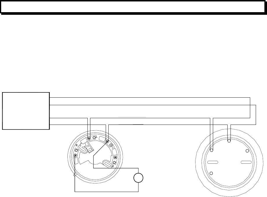
Document: LT0273 MX4428 MXP Engineering / Technical Manual
Device Information and Programming
Issue 1.5 24 March 2006 Page 3-25
3.11 MUB UNIVERSAL BASE
3.11.1 GENERAL
The MUB accommodates any of the MX 814 series detectors, and may also have an 814RB,
814SB, or MkII Sounder Base plugged into it.
3.11.2 MUB AND 5B WIRING
Figure 3.1 shows the wiring for a MUB and 5B, including optional wiring of a remote
indicator.
Tyco E500Mk2
Remote Indicator
+
-
TYCO MUB (M614)
MINERVA
UNIVERSAL
BASE
TYCO 5B
5“ UNIVERSAL
BASE
MXP
AR
AL+
-
+
-
L2
L1
L
R
+
M
L2
L
L1
R
L1
LL2
Figure 3.1 MUB and 5B Wiring
3.11.3 REMOTE INDICATOR WIRING
A remote indicator may be wired to an MUB, Relay Base, or Sounder Base as shown for
example in Figure 3.1.
A single Remote Indicator may be wired up to a number of detector bases, so that it turns on
if any one of the detectors turns it on. The R terminals of the detectors involved should be
looped together.
This common group must not include an isolator base or extend across an isolator base.
The brightness may increase slightly if more than one detector turns on the remote indicator.

MX4428 MXP Engineering / Technical Manual Document: LT0273
Device Information and Programming
Page 3-26 24 March 2006 Issue 1.5
3.12 5BI ISOLATOR BASE
3.12.1 GENERAL
The 5BI base is designed for isolating short circuited sections of the analog loop. For
instance it can be used where the loop wiring crosses zone boundaries to prevent a short
circuit from affecting more than one zone. When isolator bases are used, it is strongly
recommended that two additional isolator bases (possibly with no detectors inserted) be
installed at the start and end of the loop, close to the MXP.
Isolator bases may also be used to join multiple lines together in a single star arrangement,
for example when a number of conventionally wired zones are being converted to MX and a
loop cannot be wired.
Refer to section 4.1 for more details on the analog loop configuration.
There is a limit to the number of other devices which may be connected on the section of
cable between isolator bases. Calculate the sum of the “IB Units” from Table 3-2 for each
section of cable. The sum for each section must not exceed 100.
A section of cable is the portion between isolator bases or between an isolator base and the
MXP, or if a star configuration or tee is being used, between an isolator base and the end of
the cable.
3.12.2 SPECIFICATIONS
Line Connections IN M(–), L1(+)
Line Connections OUT L2(–), L1(+)
Remote LED Connection R(–), L1(+)
Supply Voltage 20Vdc - 40Vdc
Supply Current 80uA (typical quiescent)
Dimensions 110mm (diameter) x 22mm (excluding detector)
Weight 80g
3.12.3 WIRING
Figure 3.2 shows wiring for an 5BI, including connection of an external remote indicator.
Note that a common remote indicator may not be wired to a set of bases which are on
different sides of an isolator base.
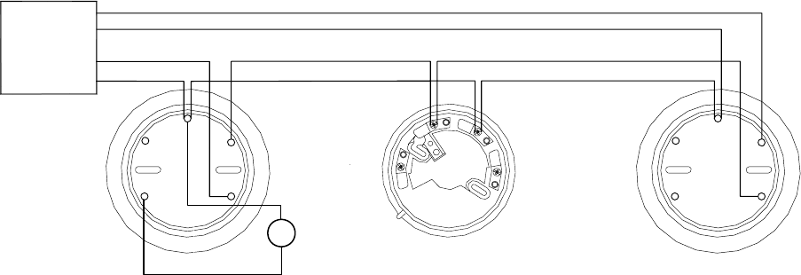
Document: LT0273 MX4428 MXP Engineering / Technical Manual
Device Information and Programming
Issue 1.5 24 March 2006 Page 3-27
TYCO 5BI
TYCO 5BI
TYCO MUB
ISOLATOR
ISOLATOR
UNIVERSAL
BASE
BASE
BASE
-
AL
MXP
AR
-
+
+
+ +
-
M M
L2 L2
R
L2
L L
L1 L1
L
L1
Tyco E500Mk2
Remote Indicator
(controlled by MX4428)
+
-
R R
M M
L1 L1
L L
L2 L2
LL1
M and L2 connections to Isolator Base are s
y
mmetrical and can be transposed without affectin
g
operation
Figure 3.2 5BI Wiring

MX4428 MXP Engineering / Technical Manual Document: LT0273
Device Information and Programming
Page 3-28 24 March 2006 Issue 1.5
3.13 814RB RELAY BASE
3.13.1 GENERAL
The 814RB detector base is designed as a low cost output device. The relay is controlled by
the detector which is plugged into the base, but the operation of the relay can be quite
separate from the operation of the detector. (Refer to section 3.3.)
The 814RB Relay Base provides two sets of volt-free, change-over contacts capable of
switching ancillary equipment rated at up to 1A resistive @ 30Vdc. One set is labelled NO,
C, NC (for normally open, common, and normally closed.) The other set is labelled 1 for NC,
2 for C, and 3 for NO. The terminals accept a single cable of up to 2.5 sqmm. Relay
operation is controlled by the MX4428 via an output from the detector. Hence, a detector
must be fitted to the base in order for the relay to operate as the relay base does not have
its own address.
The 814RB may be plugged into a MUB standard base, 5B standard base, or 5BI isolator
base, or mounted directly on the ceiling or wall.
3.13.2 SPECIFICATIONS
Line Connections L(–), L1(+)
Remote LED Connection R(–), L1(+)
Supply Voltage 20Vdc - 40Vdc
Supply Current 50uA (typical quiescent)
100uA (output active)
Relays Two changeover volt-free contacts
Switching current: 1A @ 30V dc
Resistance: On: 50mΩ Off: > 1 x 10⁹Ω .
Switching time: <10ms
Life expectancy: 100,000 operations
Dimensions 110mm (diameter) x 37mm (excluding detector)
Weight 153g
3.13.3 WIRING
Refer to Figure 3.3 for details of the relay terminals. Loop wiring and remote LED wiring is
the same as the MUB, refer to Figure 3.1. Contact wiring connects to the following terminals
NC Normally Closed
C Common
First Pole
NO Normally Open
1 Normally Closed
2 Common
Second Pole
3 Normally Open
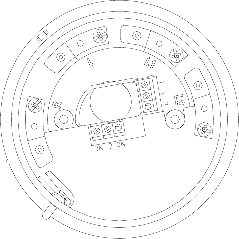
Document: LT0273 MX4428 MXP Engineering / Technical Manual
Device Information and Programming
Issue 1.5 24 March 2006 Page 3-29
Figure 3.3 Relay Base

MX4428 MXP Engineering / Technical Manual Document: LT0273
Device Information and Programming
Page 3-30 24 March 2006 Issue 1.5
3.14 814SB SOUNDER BASE
3.14.1 GENERAL
The 814SB detector base is designed as a low cost warning device. One of three different
tones may be selected (none of which are AS2220 compliant), and three sound levels are
selectable. Note that the current taken by a sounder base is very much higher than most
other loop devices, and the number of sounder bases on a loop is limited by the available
current.
The sounder is controlled by the detector which is plugged into the base, but the operation of
the sounder can be quite separate from the operation of the detector. (Refer to section 3.3.)
The tone switch allows selection of one of three different tones –
1 - continuous tone (825Hz)
2 - fast sweep (saw tooth envelope at 15Hz)
3 - slow sweep (saw tooth envelope at 5Hz) (Factory Setting)
The volume switch provides three different levels of loudness:
1 - 70dB(A) (quiet)
2 - 80 dB(A) (medium)
3 - 90 dB(A) (loud) (Factory Setting)
The 814SB may be plugged into a MUB standard base, 5B standard base, or 5BI isolator
base, or mounted directly on the ceiling or wall.
3.14.2 SPECIFICATIONS
Line Connections L(–), L1(+)
Remote LED Connection R(–), L1(+)
Supply Voltage 20Vdc - 40Vdc
Supply Current 400uA (typical quiescent)
9mA (active in QUIET setting)
12mA (active in MEDIUM setting)
15mA (active in LOUD setting)
Dimensions 110mm (diameter) x 37mm (excluding detector)
Weight 163g
3.14.3 WIRING
Wiring is the same as the MUB, refer to Figure 3.1.

Document: LT0273 MX4428 MXP Engineering / Technical Manual
Device Information and Programming
Issue 1.5 24 March 2006 Page 3-31
3.15 MKII SOUNDER BASE
3.15.1 GENERAL
The MkII Sounder Base is a range of detector bases which are designed as low cost warning
devices, some of which are loop powered and others are externally powered. The sounder is
controlled by the detector which is plugged into the base, but the operation of the sounder
can be quite separate from the operation of the detector. (Refer to section 3.3.)
The MkII Sounder Bases cannot be plugged into other bases. They must be mounted
directly on the ceiling or wall.
At the time of writing, the MkII Sounder Bases are not SSL approved to AS4428. However
they may be used for supplementary local sounders.
3.15.2 SPECIFICATIONS
Line Connections L(–), L1(+)
Remote LED Connection R(–), L1(+)
Supply Voltage 20Vdc - 40Vdc
Quiescent Supply Current 200uA (ex MX loop)
Dimensions 110mm (diameter) x 37mm (excluding detector)
Weight 186g
802SB 901SB 812SB 912SB
Power Source Loop 24VDC Loop 24VDC
Adjustable volume Yes No
Volume 68-90dBA 100dBA
Minimum Volume Current
Consumption 1.2mA (loop) 1.2mA (ext
supply) N/A
Maximum Volume Current
Consumption 6.8mA (loop) 6.8mA (ext
supply) 21mA (loop) 21mA (ext
Supply)
Tone 1 Dutch Slow Sweep (AS2220 Evacuate)
Tone 2 Temporal 4
Tone 3 Slow Sweep
Tone 4 March Time Beep
Tone 5 Fast Sweep
Tone 6 Temporal 3 (ISO8201 Evacuate)
Tone 7 Alternating
Tone 8 Continuous
3.15.3 WIRING
Wiring for the 802SB and 812SB is the same as the MUB, refer to Figure 3.1. The 901SB
and 912SB wiring is similar, but they also require a 24V connection. Refer to the installation
sheet supplied with these bases.
For the 901SB and 912SB, it is recommended that the external supply covers only one zone,
or the power wiring be arranged so that an open circuit in the power feed cannot affect more
than one zone. A loop arrangement with supervision and a reverse-feed relay can be used to
achieve this - refer to Product Bulletin PBF0200.

MX4428 MXP Engineering / Technical Manual Document: LT0273
Device Information and Programming
Page 3-32 24 March 2006 Issue 1.5
3.16 MIM800 AND MIM801 MINI INPUT MODULES
3.16.1 GENERAL
The MIM800 and MIM801 Mini Input Modules are suitable for interfacing voltage free
contacts such as switches, relay contacts, flow switches, or non-indicating detectors.
Dedicated Manual Call Point products are available that have the MIM800 or MIM801
mounted on the back of an MCP. Refer to sections 3.18 and 3.19.
Both the MIM800 and MIM801 may be used in normally open or normally closed
configurations, and the normally open configuration may or may not include short circuit fault
monitoring. Refer to Figure 3.4 for wiring topology.
The normal response time to an input change of state is 0 – 5 seconds, as each device is
polled at 5 second intervals by the MXP. If faster operation is required, interrupt operation
can be enabled. Interrupt operation allows a change to be signalled by the device so that the
MXP detects the change immediately, rather than waiting for the next poll of the device.
To interrupt on closing contacts, the MIM800 is required. To interrupt on opening contacts,
the MIM801 is required. An interrupt can be generated on only the transition from normal to
alarm, transitions from alarm to normal will always require up to 5 seconds to be recognised.
Fault supervision is provided by a 200Ω EOL resistor - open circuit fault in a normally open
configuration and short circuit fault in a normally closed configuration. In addition the
normally open configuration can be programmed to also generate fault on short circuit. In
this case only one alarm contact is allowed, a 100Ω resistor must be wired in series with the
alarm contacts, and the fault threshold must be specially programmed. (Set Parameter 2 to
176 for a MIM800 and parameter 5 to 40 for a MIM801).
The input wiring should be limited to less than 10m in length and located well away from all
electrical noise sources.
Recognition of a fault condition takes about 30 seconds.
The MIM800 and MIM801 have screw terminals for an Alarm Indicator LED. No series
resistor is required. A current of about 2.5mA will be supplied when the LED is on.
WARNING
DO NOT JOIN INPUT WIRING BETWEEN MODULES OR CONNECT TO ANYTHING
OTHER THAN VOLTAGE FREE CONTACTS
3.16.2 MIM800 / MIM801 SPECIFICATIONS
Dimensions Height: 13mm Width: 48mm Depth: 57mm
Weight 22g
Line Connections L-, L+
Supply Voltage 20V – 40V
Supply Current Standby Current : 275uA (typical)
LED on : 2.8mA (typical)
Contact Inputs Monitoring Voltage 5V
Line Resistance (MIM800 and all N/O) 10Ω max
Line Resistance (MIM801 N/C) 50Ω max
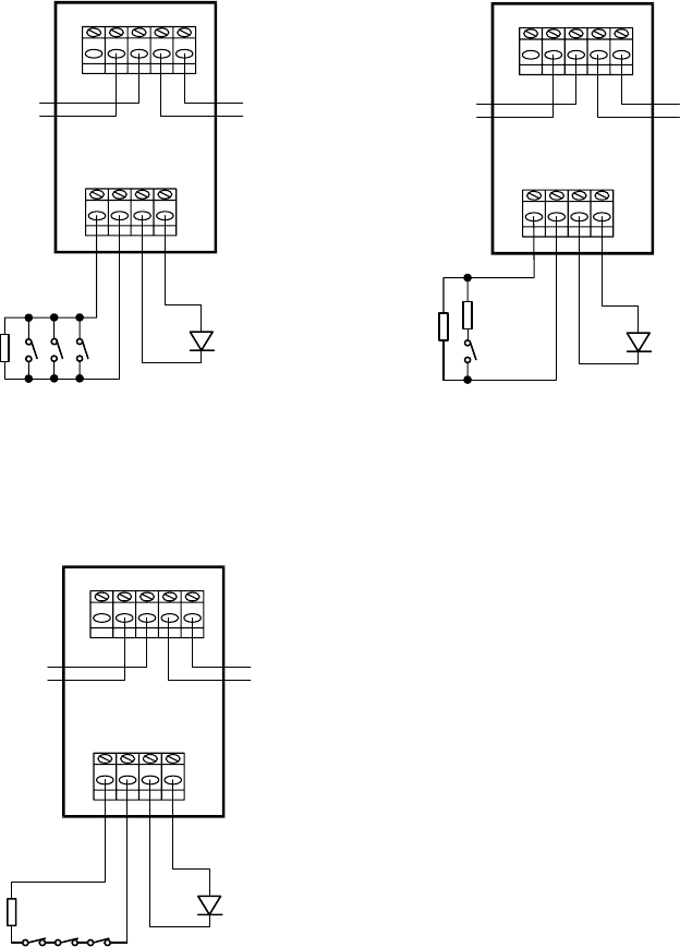
Document: LT0273 MX4428 MXP Engineering / Technical Manual
Device Information and Programming
Issue 1.5 24 March 2006 Page 3-33
Maximum input cable length 10m
EOL 200Ω + / - 5%.
Alarm Resistance 100Ω + / - 5%. (if used)
3.16.3 FIELD WIRING
TB1
TB1
TB2
TB2
L+ L+
L+ L+
L- L-
L- L-
NEXT
DEVICE NEXT
DEVICE
PREVIOUS
DEVICE PREVIOUS
DEVICE
200
ohm
EOL
200
ohm
EOL
100
ohm
ANALOG LOOP ANALOG LOOP
MIM800
Mini Module MIM800
Mini Module
Sh Sh
IN- IN+ O- O+ IN- IN+ O- O+
LED LED
TB1
TB2
L+ L+L- L-
NEXT
DEVICE
PREVIOUS
DEVICE
200
ohm
EOL
ANALOG LOOP
MIM801
Mini Module
Sh
IN- IN+ O- O+
LED
Normally Open
(default for MIM800, option for MIM801.)
N/O with S/C fault
(for MIM800 or MIM801)
Normally Closed
(
default for MIM801,option for MIM800
)
Requires Param_2 = 176
(
MIM800
),
Param_5 = 40 (MIM801)
Inputs must be voltage free.
Figure 3.4 CLEAN CONTACT DEVICE CONNECTION TO MIM800 / MIM801
3.16.4 MX4428 PROGRAMMING OPTIONS - MIM800 / MIM801
The mode sets the operating configuration.
For the MIM800 the default value of 4 selects normally open operation with no interrupt. A
mode of 6 selects normally open with interrupt on alarm. Changing parameter 2 to 176
enables short circuit fault detection. Setting the mode to 5 enables normally closed
operation.

MX4428 MXP Engineering / Technical Manual Document: LT0273
Device Information and Programming
Page 3-34 24 March 2006 Issue 1.5
For the MIM801 the default value of 15 selects normally closed operation with interrupt on
alarm (e.g. for New Zealand callpoints). Setting the mode to 13 disables interrupt on alarm
(e.g. for heat circuits or other non-immediate alarm conditions). Setting the mode to 12
enables normally open operation and then changing parameter 5 to 40 enables short circuit
fault detection.
Normally Open
Parameter Description Default
4 No interrupt Mode 6 Interrupt 4
P0 Normal to alarm threshold 122
P1 Normal to o/c threshold 50
Alarm to s/c threshold
0 No alarm resistor
P2
176 100 ohm alarm resistor
0
P3
P4
P5
P6
Normally Closed
Parameter Description Default
Mode Change to 5 to select normally closed operation 4
P0 Normal to s/c threshold 122
P1 Normal to alarm threshold 50
P2
P3
P4
P5
P6
3.16.5 MX4428 PROGRAMMING OPTIONS - MIM801
Normally Open
Parameter Description Default
Mode Change to 12 to select normally open operation 15
P0
P1
P2
P3 Normal to alarm threshold 110
P4 Normal to o/c threshold 170
Alarm to s/c threshold
0 No alarm resistor
P5
40 100 ohm alarm resistor
0
P5
P6
Normally Closed
Parameter Description Default
Value Description
13 No interrupt
Mode
15 Interrupt, does not use AVF even if enabled
15
P0
P1
P2
P3 Normal to s/c threshold 110
P4 Normal to alarm threshold 170
P5
P6

Document: LT0273 MX4428 MXP Engineering / Technical Manual
Device Information and Programming
Issue 1.5 24 March 2006 Page 3-35
3.17 CIM800 CONTACT INPUT MODULE
3.17.1 GENERAL
The CIM800 Contact Input Module is suitable for interfacing voltage free contacts, e.g.
switches, relay contacts, flow switches, or non-indicating detectors. It has two inputs, the
state of which are ORed together to generate the point status. Therefore unused inputs must
be terminated with the EOL resistor.
The CIM800 may be used in normally open or normally closed configurations, and the
normally open configuration may or may not include short circuit fault monitoring. Refer to
Figure 3.5 for wiring topology.
The normal response time to an input change of state is 0 – 5 seconds, as each device is
polled at 5 second intervals by the MXP. If faster operation is required, interrupt operation
can be enabled. Interrupt operation allows a change to be signalled by the device so that the
MXP detects the change immediately, rather than waiting for the next poll of the device.
The CIM800 can only interrupt on “closing” contacts, and interrupt operation is only
applicable for normally open contacts. Transitions from closed to open will always require up
to 5 seconds to be recognised. Therefore it cannot be used for callpoints on NZ systems.
Fault supervision is provided by default with a 200Ω EOL resistor - open circuit fault in a
normally open configuration and short circuit fault in a normally closed configuration. In
addition the normally open configuration can be programmed to also generate fault on short
circuit. In this case only one alarm contact is allowed, a 100Ω resistor must be wired in
series with the alarm contacts, and the fault threshold must be specially programmed - set
Parameter 2 to 176.
Recognition of a fault condition takes about 30 seconds.
WARNING
DO NOT JOIN INPUT WIRING BETWEEN INPUTS OR MODULES OR TO ANYTHING
OTHER THAN VOLTAGE FREE CONTACTS
3.17.2 CIM800 SPECIFICATIONS
Dimensions Height: 61mm Width: 84mm Depth: 25mm
Weight 100g
Line Connections L-, L+
Supply Voltage 20V – 40V
Supply Current Standby Current : 275uA (typical)
LED on : 2.8mA (typical)
Contact Inputs Monitoring Voltage 5V
Line Resistance 10Ω max
EOL 200Ω + / - 5%.
Alarm Resistance 100Ω + / - 5% (if used).
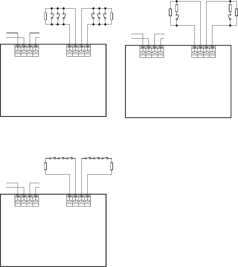
MX4428 MXP Engineering / Technical Manual Document: LT0273
Device Information and Programming
Page 3-36 24 March 2006 Issue 1.5
3.17.3 FIELD WIRING
CIM800 CONTACT MODULE CIM800 CONTACT MODULE
CIM800 CONTACT MODULE
TB1 TB1
TB1
TB2 TB2
TB2
L+ L+
L+
A+ A+
A+
L+ L+
L+
B+ B+
B+
L- L-
L-
A- A-
A-
L- L-
L-
B- B-
B-
NEXT
DEVICE NEXT
DEVICE
NEXT
DEVICE
PREVIOUS
DEVICE PREVIOUS
DEVICE
PREVIOUS
DEVICE
200
ohm
EOL
200
ohm
EOL
100
ohm 100
ohm 200
ohm
EOL
200
ohm
EOL
200
ohm
EOL
200
ohm
EOL
ANALOG LOOP ANALOG LOOP
ANALOG LOOP
Normally Open Normally Open, S/C = Fault
Normally Closed
Requires Param_
2
=
1
7
6
Unused inputs (A or B) must be terminated with
a 200 ohm EOL resistor.
A and B inputs must be voltage free.
Figure 3.5 CLEAN CONTACT DEVICE CONNECTION TO CIM800
3.17.4 MX4428 PROGRAMMING OPTIONS - CIM800
The mode sets the operating configuration. The default value of 8 selects normally open
with no interrupts, whereas a value of 10 enables interrupt on alarms.
A mode of 9 selects normally closed operation. Interrupt is not available.

Document: LT0273 MX4428 MXP Engineering / Technical Manual
Device Information and Programming
Issue 1.5 24 March 2006 Page 3-37
Normally Open
Parameter Description Default
8 No interrupt Mode 10 Interrupt 8
P0 Normal to alarm threshold 122
P1 Normal to o/c threshold 50
Alarm to s/c threshold
0 No alarm resistor
P2
176 100 ohm alarm resistor
0
P3
P4
P5
P6
Normally Closed
Parameter Description Default
Mode Change to 9 to select normally closed operation 8
P0 Normal to s/c threshold 122
P1 Normal to alarm threshold 50
P2
P3
P4
P5
P6
MX4428 MXP Engineering / Technical Manual Document: LT0273
Device Information and Programming
Page 3-38 24 March 2006 Issue 1.5
3.18 CP820 MANUAL CALL POINT
3.18.1 GENERAL
The CP820 Manual Call Point consists of a MIM800 mounted on a Break Glass Switch
assembly. The MIM800 is factory programmed with a different type-id to allow the CP820 to
be distinguished from a generic MIM800.
The normal response time to an input change of state is 0 – 5 seconds, as each device is
polled at 5 second intervals by the MXP. If faster operation is required, interrupt operation
can be enabled. Interrupt operation allows a change to be signalled by the device so that the
MXP detects the change immediately, rather than waiting for the next poll of the device.
The CP820 is made without an EOL resistor and no wiring fault monitoring is provided as all
the wiring is internal.
The CP820 device processing will not use AVF, even if it is enabled for the circuit the CP820
is allocated to.
3.18.2 MX4428 PROGRAMMING OPTIONS - CP820
The mode determines whether interrupt operation is enabled or not. A value of 0 (default)
means interrupt is disabled, while a value of 2 enables interrupt operation.
Parameter Description Default
0 No interrupt Mode 2 Interrupt 0
P0 Normal to alarm threshold 122
P1
P2
P3
P4
P5
P6

Document: LT0273 MX4428 MXP Engineering / Technical Manual
Device Information and Programming
Issue 1.5 24 March 2006 Page 3-39
3.19 FP0838 / FP0839 MANUAL CALL POINTS
3.19.1 GENERAL
The FP0838 and FP0839 Manual Call Points consist of a MIM801 mounted on an 1841
Break Glass Switch assembly. They are designed for normally closed contacts as is required
in New Zealand.
The normal response time to an input change of state is 0 – 5 seconds, as each device is
polled at 5 second intervals by the MXP. As faster operation is required in New Zealand,
interrupt operation should be enabled for the MIM801. Interrupt operation allows a change
to be signalled by the device so that the MXP detects the change immediately, rather than
waiting for the next poll of the device. Default programming of the MIM801 selects open
circuit alarm and interrupt operation.
The FP0838 and FP0839 Call Points include a LED visible from the front. This lights on
alarm and can be programmed to blink when the MIM801 is polled. Operation is otherwise
as for the MIM801.
3.19.2 MX4428 PROGRAMMING OPTIONS - FP0838 / FP0839
These Call Points are programmed as MIM801s. Refer to section 3.16.5.

MX4428 MXP Engineering / Technical Manual Document: LT0273
Device Information and Programming
Page 3-40 24 March 2006 Issue 1.5
3.20 DIM800 DETECTOR INPUT MONITOR
3.20.1 GENERAL
The DIM800 Detector Input Module is suitable for interfacing conventional non-addressable
detectors e.g. heat detectors, smoke detectors, beam detectors, etc, onto the MXP loop.
Alarm and o/c fault conditions are determined by the MXP. An alarm can be recognised
within 5 seconds if AVF is not enabled for the circuit, or 15-20 seconds if AVF is enabled.
Recognition of a fault condition takes about 30 seconds.
The DIM800 has two inputs, the state of which are ORed to generate the point status.
Therefore unused inputs must be terminated with the correct EOL.
The DIM800 provides electrical isolation of the detector circuit(s) from the MXP loop.
The DIM800 requires an external supply to power the detector circuit and the module itself. If
external power is not provided the DIM800 will not respond to polls and a NODE FAIL fault
will be indicated. The voltage of the external supply at the DIM800 is critical to ensure
compatibility with particular detectors. Refer to Table 3-4.
The external supply cannot be derived from the MXP loop or the MX4428 responder loop,
and in some cases cannot be taken from the MX4428 main power supply. Where the voltage
range is critical, it is recommended that a dedicated power supply and battery be used. The
voltage drop in the wiring from the power supply to the DIM800 must be calculated to ensure
the supply voltage at the DIM800 is within specification. If multiple DIM800s are on the same
cable, then the maximum current drawn by each DIM800 (e.g. input short circuit) must be
used.
The external supply must comply with AS4428.1 and AS4428.5 and should be set to 27.3V
by default. The wiring from a common PSU to multiple DIM800 modules must be arranged
so that a single open circuit does not prevent alarms from being generated in more than one
zone. A loop arrangement with supervision and a reverse-feed relay can be used to achieve
this - refer to Product Bulletin PBF0200.
If the detector itself requires a 24V power supply that needs to be switched off to reset the
detector, e.g. some beam detectors, refer to Product Bulletin PBF0213 for a suitable
arrangement. Do not use the SW+ and SW- terminals available on early DIM800 models.
Field wiring of the DIM800 is shown in Figure 3.6. The wiring instructions for the particular
detector/base must be referred to as some detectors break the negative line, and others the
positive line, when the detector is removed.
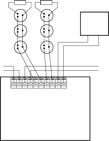
Document: LT0273 MX4428 MXP Engineering / Technical Manual
Device Information and Programming
Issue 1.5 24 March 2006 Page 3-41
DIM800 DETECTOR
INPUT MONITOR
L+ L+L- L-
NEXT
DEVICE
PREVIOUS
DEVICE
A
NALOG LOOP ANALOG LOOP
A+ A- B+ B-
+24V
COM
EXT
PSU
+-
4k7 EOL4k7 EOL
Conventional
Detectors
(refer appropriate
wiring diagrams)
Refer text for
voltage
requirement
s
Unused inputs (A or B) must be
terminated with 4k7 EOL.
Figure 3.6 DIM800 Field Wiring
3.20.2 DIM800 SPECIFICATIONS
Dimensions Height: 61mm Width: 84mm Depth: 25mm
Weight 100g
Line Connections L-, L+
Loop Supply Voltage 20V – 40V
Loop Supply Current Standby/Alarm Loop Current : 100uA (typical)
EOL 4k7 + / - 1%.
Detector Load 3.0mA max per circuit
External Current (normal) 7.5mA (excluding detectors)
External Current (shorted) 30 - 50mA (depends on supply voltage)
External Supply Voltage Refer to Table 3-4 for each detector.
Maximum Line Resistance 50Ω (with detectors)
1750Ω (with hard contacts only)
Short Circuit Fault Option Maximum line resistance 34Ω
Minimum Detector Alarm Voltage 5.0V

MX4428 MXP Engineering / Technical Manual Document: LT0273
Device Information and Programming
Page 3-42 24 March 2006 Issue 1.5
3.20.3 DIM800 DETECTOR COMPATIBILITY
Series Model Max Qty External Supply
Voltage at DIM
614P Photo Detector 25 20.0V – 28.7V
614I Ionisation Detector 38 20.0V – 28.7V
614CH Carbon Monoxide + Heat Detector 32 20.0V – 28.7V
614T Heat Type A, B, C, D 23 20.7 – 28.7V
MD614 Heat Detector 40 20.7V - 28.7V
MR614 Photo Detector 22 20.7V - 28.7V
MR614T HPO Detector 21 20.7V - 28.7V
MU614 CO Detector 40 20.7V - 28.7V
MF614 Ionisation Detector 30 20.7V - 28.7V
Minerva
T614 Heat Type A, B, C, D 23 20.7V - 28.7V
4098 – 9603EA Ionisation Detector 24 20.0V - 28.7V
4098 – 9601EA Photo Detector 24 20.0V - 28.7V
Simplex 4098 – 9618EA,-9619EA,-9621EA Heat
Detectors 24 20.0V - 28.7V
P24B Photoelectric Detector 24 20.7V - 24.7V
P29B Photoelectric Detector 20 20.7V - 26.7V
C24B Ionisation Detector 40 20.7V - 26.7V
C29B (Ex) Ionisation Detector 40 20.7V - 26.7V
R23B Flame Detector* 20 20.7V - 24.7V
R24B Flame Detector 3 22.7V - 28.7V
DO1101 Photo Detector* 16 21.7V - 27.7V
DLO1191 Beam Detector* 1 22.7V - 28.7V
P136 Duct Sampling Unit 5 20.0V - 28.7V
T56B Heat Detector 40 20.0V - 28.7V
All above Olsen Detectors with Z52B, Z54B,
Z54B Mk2, Z56, Z500 base as appropriate
Olsen
T56B Heat Detector with
Z52B, Z55B, Z56N, Z500N Base 40 20.0V - 28.7V
System
Sensor 885WP-B Weatherproof Heat Detector
Type B *@ 40 20.0V – 28.7V
- Hard Contact Devices (T54B, B111, etc) 40 20.0V - 28.7V
Hard contact devices must be rated for at least 30V and currents up to 50mA.
* Not an SSL Listed combination
@ Remote indicator output cannot be used in common with Tyco 614 series or the
Minerva M614 series (and most other Tyco/Olsen) detectors.
Table 3-4 Conventional Detector Compatibility
3.20.4 MX4428 PROGRAMMING OPTIONS - DIM800
Parameter Description Default
Value Description
0 Short = Alarm
Mode
1 Short = Fault
0
P1 Normal to Alarm Threshold 51
P2 Normal to Fault Threshold 22
P3 Supply Fault Threshold 60 (this is MXP default used if
MX4428 value = 0).
On the latest revision of
DIM800, the threshold cannot
be usefully varied by changing
this parameter.
P4 Alarm to Short Threshold 225 (this is MXP default used
if MX4428 value = 0)
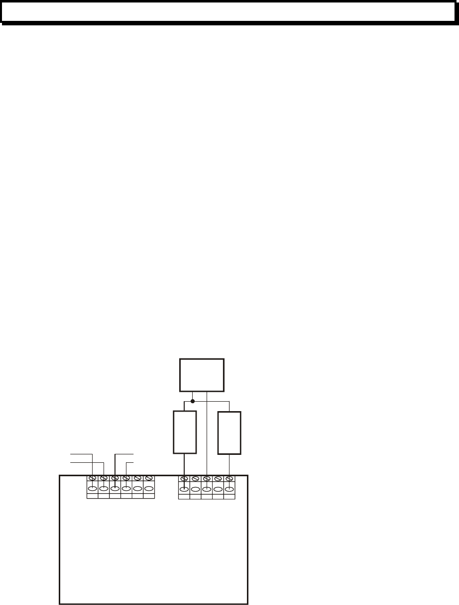
Document: LT0273 MX4428 MXP Engineering / Technical Manual
Device Information and Programming
Issue 1.5 24 March 2006 Page 3-43
3.21 RIM800 RELAY INTERFACE MODULE
3.21.1 GENERAL
The RIM800 Relay Interface Module is suitable for relay outputs which require clean voltage
free contacts and no supervision. For example it can be used to signal states to other
systems (e.g. BMS or security systems), or to energise loads that do not need to be
supervised, e.g. Door Holders.
3.21.2 RIM800 SPECIFICATIONS
Dimensions: Height: 61mm Width: 84mm Depth: 25mm
Weight 100g
Line Connections L-, L+
Supply Voltage 20V – 40V
Supply Current Standby Current : 285uA (typical)
LED on : 2.8mA (typical)
Contact Rating 2A 30Vdc
0.6A 120Vac (not permitted by AS / NZS standards)
0.3A 240Vac (not permitted by AS / NZS standards)
3.21.3 RIM800 FIELD WIRING
The field wiring is shown in Figure 3.7.
RIM800 RELAY MODULE
TB1
TB2
L+ L+L- L-
NEXT
DEVICE
PREVIOUS
DEVICE
ANALOG LOOP
O+ O-
N/O COM N/C
PSU
Normally
Energised
Load
Normally
DeEnergised
Load
Make no connection to O+ and O- terminals
Figure 3.7 RIM800 Field Wiring

MX4428 MXP Engineering / Technical Manual Document: LT0273
Device Information and Programming
Page 3-44 24 March 2006 Issue 1.5
3.21.4 MX4428 PROGRAMMING OPTIONS - RIM800
The mode selects the control source for the RIM800 output. By default (mode = 4) the
output follows the logical relay. However if the mode is 0 then the output is controlled by the
corresponding circuit alarm state.
Parameter Description Default
Value Description
0 Controlled by Circuit Alarm
Mode
4 Controlled by Relay
4
P0
P1
P2
P3
P4
P5
P6

Document: LT0273 MX4428 MXP Engineering / Technical Manual
Device Information and Programming
Issue 1.5 24 March 2006 Page 3-45
3.22 SNM800 SOUNDER NOTIFICATION MODULE
3.22.1 GENERAL
The SNM800 Sounder Notification Module is suitable for relay outputs which require
supervision of the load wiring and optional supervision of the DC power supply (if any).
When inactive, a reverse polarity supervision voltage is applied to the load wiring. The load
devices must therefore have internal or external reverse blocking diodes.
The load supervision can detect short and open circuit states on the load wiring only when
the relay is inactive.
The 24V DC supply may be supervised.
The load must be isolated from ground and all voltage sources. All inductive loads (e.g. bells
or relays) must have back-emf diodes or other noise clamping devices fitted.
Recognition of a fault condition takes about 30 seconds.
3.22.2 SNM800 SPECIFICATIONS
Dimensions Height: 61mm Width: 84mm Depth: 25mm
Weight 100g
Line Connections L-, L+
Supply Voltage 20V – 40V
Supply Current Standby Current : 450uA (typical)
LED On : 3.0mA (typical)
Output Circuit EOL 27k ohms, 0.5 watt
Contact Rating 2A 30Vdc
Load must be isolated from ground and all supplies.
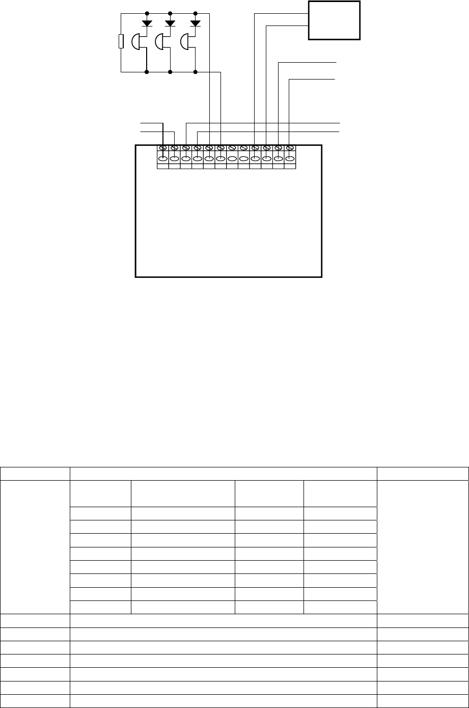
MX4428 MXP Engineering / Technical Manual Document: LT0273
Device Information and Programming
Page 3-46 24 March 2006 Issue 1.5
3.22.3 SNM800 FIELD WIRING
SNM800 SOUNDER
NOTIFICATION MODULE
L+ L+L- L-
NEXT
DEVICE
PREVIOUS
DEVICE
ANALOG LOOP
A
NALOG LOO
P
S+ S- R+ R- I+ I- I+ I-
Power
Supply
+
-
Power to
next
device
27k
0.5W
EOL
++ +
-- -
Figure 3.8 SNM800 Field Wiring
It is recommended that the external supply covers only one zone, or the power wiring be
arranged so that an open circuit in the power feed cannot affect more than one zone. A loop
arrangement with supervision and a reverse-feed relay can be used to achieve this - refer to
Product Bulletin PBF0200.
3.22.4 MX4428 PROGRAMMING OPTIONS - SNM800
The mode selects the control source for the SNM800 output, load supervision, and EOL
supervision. By default (mode = 15) the output follows the logical relay, the external supply is
supervised, and the EOL is supervised.
Parameter Description Default
Mode Output Control Monitor
Supply ? Monitor
EOL ?
8 Cct Alarm No No
9 Cct Alarm No Yes
10 Cct Alarm Yes No
11 Cct Alarm Yes Yes
12 Relay No No
13 Relay No Yes
14 Relay Yes No
Mode
15 Relay Yes Yes
15
P0
P1 Normal to o/c fault threshold 221
P2 Normal to s/c fault threshold 20
P3 Supply fault threshold 200
P4
P5
P6

Document: LT0273 MX4428 MXP Engineering / Technical Manual
Device Information and Programming
Issue 1.5 24 March 2006 Page 3-47
3.23 LPS800 LOOP POWERED SOUNDER MODULE
3.23.1 GENERAL
The LPS800 Loop Powered Sounder Module is suitable for 24V DC outputs powered by the
MX Loop. It can supply up to 75mA at 24VDC.
When inactive, a reverse polarity supervision is applied to the load wiring. The load devices
must therefore have reverse blocking diodes.
The load supervision can detect short and open circuit states on the load wiring only when
the output is inactive.
The load must be isolated from ground and all voltage sources. All inductive loads (e.g. bells
or relays) must have back-emf diodes or other noise clamping devices fitted.
Recognition of a fault condition takes about 30 seconds.
3.23.2 LPS800 SPECIFICATIONS
Dimensions Height: 87mm Width: 148mm Depth: 14mm
Weight 100g
Line Connections L-, L+
Supply Voltage 20V – 40V
Supply Current Standby Current : 450uA (typical)
Operated with load up to 8mA : 12mA.
Operated with load over 8mA : Load current + 4mA
Output Circuit ELD 22k ohms, 0.5 watt
Output Current Rating 75mA@24V nominal.
Voltage Drop 2V max
Note that the LPS800 has a minimum voltage drop of 2V between the line voltage and the
output terminals. When the loop voltage is less than 26V, the output voltage may be less
than 24V. At the minimum loop voltage of 20V, only 18V will be available for the sounder
devices. From this you must subtract the voltage drop in the wiring to the sounder devices to
obtain the voltage at the sounder device terminals. You must ensure the sounder devices
operate correctly at this voltage.
Alternatively you must design the loop so that the minimum voltage is higher than 20V and
sufficient to give the required voltage at the sounder terminals. Refer to section 3.2.2 for loop
voltage drop calculations.
The load must be isolated from ground and all supplies.
3.23.3 MX4428 PROGRAMMING OPTIONS - LPS800
The LPS800 is programmed as an SNM800. Refer to section 3.22.4.
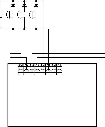
MX4428 MXP Engineering / Technical Manual Document: LT0273
Device Information and Programming
Page 3-48 24 March 2006 Issue 1.5
LPS800 LOOP POWERED
SOUNDER MODULE
L+ L+L- L-
NEXT
DEVICE
PREVIOUS
DEVICE
MX LOOP MX LOOP
S+ S- R+ R-
22k
0.5W
ELD
++ +
-- -
Figure 3.9 LPS800 Field Wiring

Document: LT0273 MX4428 MXP Engineering / Technical Manual
Device Information and Programming
Issue 1.5 24 March 2006 Page 3-49
3.24 VLC-800MX VESDA LASERCOMPACT
3.24.1 GENERAL
The VLC800 is a derivative of the standard VESDA LaserCOMPACT product family, with the
primary difference that it communicates directly on the MX loop.
VESDA LaserCOMPACT detectors provide very early warning of potential fire conditions by
drawing air samples through 25mm pipe up to 80m long. Smoke is sampled through holes in
the pipe and transported to the detector by an integrated aspirator or fan. Holes are
positioned according to the application and often follow the spacing of standard conventional
point detectors. Where necessary, sampling points can be constructed using capillary
extensions.
The VLC800 alarm sensitivity can be set to between 0.005% obscuration / m and 20%
obscuration / m. A PC plugged into the VLC800 is required to set the sensitivity, to normalise
the airflow, and perform other setup functions. The sensitivity is NOT controlled at the
MX4428.
Refer to Tyco Safety Products UK publication 17A-03-VLC for further details on installing,
commissioning and servicing the VLC-800.
3.24.2 VLC800 SPECIFICATIONS
Environment: Indoor Application only
IP Rating: IP30
Operating Temperature:
Detector Ambient: -10°C to +39°C
Sampled Air: -20°C to +60°C
Relative Humidity: 10-95% non-condensing
Dimensions:
Height: 225mm
Width: 225mm
Depth: 85mm
Weight: 1.9kg
Sampling Network:
Maximum Area Coverage: 800m2
Maximum Pipe length: 80m with up to 15* holes,
or 2 x 50m with up to 9* holes per pipe
Pipe Size: ID15 - 21mm
OD 25mm
‘*’ more holes may be used on networks designed using the VESDA Aspire
pipe modelling software.
External 24V dc:
Supply Voltage: 18 to 30V dc
Current Consumption: Standby: 225mA
Alarm: 245mA
MX Loop:
Normal: 300uA
Non operational (VLC off): 300uA
Alarm: 300uA
Alarm with external relay: dependant on the relay
Alarm with external LED: 3.3mA
Onboard relay: rated 2A @ 30V dc

MX4428 MXP Engineering / Technical Manual Document: LT0273
Device Information and Programming
Page 3-50 24 March 2006 Issue 1.5
3.24.3 MX4428 PROGRAMMING OPTIONS - VLC800
The only programmable items for the VLC800 are
1. The pre alarm threshold.
2. The source of the remote LED output.
3. The source of the onboard relay output and external relay output (they operate
together).
The VLC800 shares default values with the 814H, 814PH, and 814PHFL. However the alarm
threshold is fixed at 100 regardless of any default setting. The default pre alarm setting of 68
translates to 68% of the alarm value which although a suitable value, can be changed if
required.
Parameter Description Default
P0 Pre Alarm Threshold 68
192 plus value below
Value Relay Control Remote LED
Control Resulting
parameter
0 Circuit Alarm Circuit Alarm 192
1 Circuit Alarm Relay Logic 193
2 Circuit Alarm Point Alarm 194
4 Relay Logic Circuit Alarm 196
5 Relay Logic Relay Logic 197
6 Relay Logic Point Alarm 198
8 Point Alarm Circuit Alarm 200
9 Point Alarm Relay Logic 201
P6
10 Point Alarm Point Alarm 202
192
AVF may be applied to the circuit the VLC800 point maps to.

Document: LT0273 MX4428 MXP Engineering / Technical Manual
Device Information and Programming
Issue 1.5 24 March 2006 Page 3-51
3.25 AVF / RAD / SAD / FLOWSWITCH DELAYS
AVF/RAD or SAD or FLOWSWITCH or AVF/SAD may be configured for a “circuit” and will
apply to all input devices on the circuit except CP820 devices, and MIM801 devices with
“interrupt” enabled.
3.25.1 AVF/RAD
Note that AVF is usually unnecessary on the addressable detectors as the built in filtering
already provides significant protection against false alarms. AVF provides an additional time
delay to verify that the alarm is still present at the end of the AVF delay. It operates as
follows –
Time Action
0 Alarm detected at detector or module - not sent to MX4428.
5 seconds Reset detectors (remove power) on DIM module.
Do nothing on other modules.
10 seconds Remove reset to detectors on DIM module (re-apply power), and set alarm
count to 0 for DIM module (requiring count up to 6 for alarm recognition).
15 seconds Resample detector or module, if still in alarm condition then alarm is
transmitted to MX4428 immediately.
15 – 135
seconds Immediate recognition of alarm condition and transmission to MX4428.
135 seconds If no alarm start again.
3.25.2 SAD
All devices on circuits set up as “SAD” at the MX4428 have the “return to normal” signalled
to the MX4428 delayed by 60 seconds. If the state goes back into alarm during this time, the
timer will be reset.
3.25.3 AVF/SAD
All devices on circuits set up as “AVF/SAD” at the MX4428 delay into alarm as per AVF/RAD
and delay out of alarm as per SAD.
3.25.4 FLOWSWITCH
All devices on circuits set up as “Flowswitch” at the MX4428 have the alarm signalled to the
MX4428 delayed by 15, 30, or 60 seconds (depending on the MX4428 programming). If the
state goes out of alarm during the delay time, the timer will be reset.
MX4428 MXP Engineering / Technical Manual Document: LT0273
Device Information and Programming
Page 3-52 24 March 2006 Issue 1.5
THIS PAGE INTENTIONALLY LEFT BLANK

Document: LT0273 MX4428 MXP Engineering / Technical Manual
Analog Loop Design Considerations
Issue 1.5 24 March 2006 Page 4-1
CHAPTER 4
ANALOGUE LOOP DESIGN CONSIDERATIONS

MX4428 MXP Engineering / Technical Manual Document: LT0273
Analog Loop Design Considerations
Page 4-2 24 March 2006 Issue 1.5
4.1 ANALOGUE LOOP CONFIGURATION SELECTION
4.1.1 LINES & LOOPS
The interface between the MXP and its addressable devices requires two wires.
The MXP has two lines (“left” and “right”) which are designed to be connected in a loop.
The LOOP configuration is generally preferred and indeed will often be mandatory for
compliance with standards as discussed below.
However the MXP can be used to connect to multiple lines in a star configuration. Dual line
mode is not supported.
4.1.2 LOOP FAULT TOLERANCE
Standards require that a line/loop fault condition cause minimal disruption to the system's
ability to detect and transmit alarms to the Fire Panel. The MXP achieves this in the
following way .....
The MXP has access to each device from both ends of the loop. The loop is normally
sourced from “left” and monitored at the “right” terminals. Disappearance of 40V power at the
“right” end, due to an open circuit FAULT on either the + or – wires, can be detected
(causing a FAULT event to be sent to the MX4428 Master) and corrected by switching the
Line driver onto the “right” terminals. The LOOP mode is therefore inherently fault tolerant to
any one open circuit on any one of the 2 wires.
However, a short circuit on the loop will, in general, cause the MXP to loose communication
with all devices. Thus it is recommended that isolator bases be used to minimise the loss
due to a short.
When designing fire alarm systems, the designer should be aware of any local statutory
requirements, as well as those of AS1670.1 and NZS4512.
4.1.3 AS1670.1 DESIGN REQUIREMENTS
Australian Standard AS1670.1 sections 3.1 and 3.2 require the analogue loop to comply with
the following:
• The maximum number of actuating devices (i.e. detectors and input modules) in an
alarm zone shall not exceed 40.
• A single short circuit shall not disable more than 40 devices connected to the MXP
loop/line. This means than if more than 40 devices are to be connected to an MXP, short
circuit isolators must be used. The count of 40 includes conventional detectors
connected to a DIM800 or other ancillary input device
4.1.4 NZS4512 DESIGN REQUIREMENTS
• Isolator Bases must be fitted between zones (or on the first device either side of a zone
boundary) so that a single short circuit or break will affect no more than one zone.
• In many cases the tones produced by the 814SB sounder base are not acceptable.
Refer to NZS4512 for detailed requirements.

Document: LT0273 MX4428 MXP Engineering / Technical Manual
Analog Loop Design Considerations
Issue 1.5 24 March 2006 Page 4-3
4.2 ANALOGUE LOOP/LINE LAYOUTS
4.2.1 LINE MODE
The MXP is designed to run in LOOP mode only. The dual line mode of the MPR is not
supported. However a star configuration can be used, refer to section 4.2.3.
4.2.2 LOOP DESIGN WITH SHORT CIRCUIT ISOLATORS
There are two main reasons for using isolator bases on the analogue loop.
(i) When the MXP powers up a line/loop, it will only have to power up one section of the
line/loop at a time, reducing the power required by the MXP from the MX4428 supply
loop during startup.
(ii) If the loop is shorted then the MXP will loose communication with only those devices
on the shorted section between 2 isolators. If every detector was mounted on an
isolator base, then all detectors would remain functional in the event of a single short
circuit.
Refer to Figure 4.1 for an example of loop wiring with Isolator Bases.
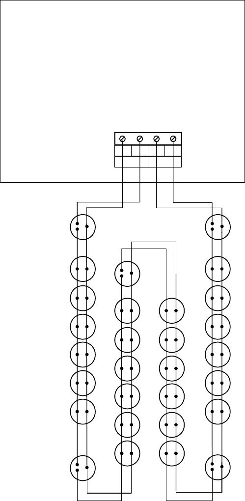
MX4428 MXP Engineering / Technical Manual Document: LT0273
Analog Loop Design Considerations
Page 4-4 24 March 2006 Issue 1.5
MXP
MX DETECTOR LOOP
AL AR
+VE +VE
-VE -VE
L1
L1
L1 L1
L1
M
M
M
M
M
L2
L2
L2
L2
L2
L1
L1
L1
L1
L1
L1
L1
L1
L1
L1
L1
L1
L1
L1
L1
L1
L1
L1
L1
L1
L1
L1
L1
L1
IB
IB
IB
IB IB
L
L
L
L
L
L
L
L
L
L
L
L
L
L
L
L
L
L
L
L
L
L
L
L
Figure 4.1 Loop with Isolator Bases
Note 1: Although it is not essential to have Isolator Bases between the MXP and the first /
last device on the loop, greater protection is provided by doing so. It is recommended that
the cable between the MXP line terminals and the adjacent Isolator Bases should be kept as
short as possible, and have no devices attached to it. These Isolator Bases could be located
at the MXP without detectors plugged into them.
Note 2: The maximum number of devices between Isolator Bases is 100 or less depending
on the devices. Refer to section 3.2.4.
Note 3: The M and L2 connections are interchangeable.
Document: LT0273 MX4428 MXP Engineering / Technical Manual
Analog Loop Design Considerations
Issue 1.5 24 March 2006 Page 4-5
4.2.3 STAR CONNECTION OF ANALOGUE LINES
It is not always necessary to connect addressable systems as loops, especially if an existing
conventional detector system is being converted to addressable detectors. As the existing
detector zone cables probably already terminate at the main panel, it is possible to connect
these in a star connection to the MXP as shown in Figure 4.2.
The two line terminals should be joined together as shown in Figure 4.2. The total length of
cable connected to the MXP should not exceed 2000m.
Because shorting the cable in one line will short out all the other lines connected to the same
MXP, it is recommended that 5BI Isolator Bases be fitted at the start of each line and then
placed every 20 - 40 devices along each line. (Refer to section 3.2.4 for the calculations to
determine where the isolator bases must be positioned.) The cabling from the MXP to the
initial Isolator Bases should be as short as possible. In fact 5BI Isolator bases without
detectors can be used at the star junction point.
Note: The Star Connection is not recommended for new installations. A loop configuration
should be used as it offers open circuit fault protection and with Isolator Bases, short circuit
protection.
4.2.4 SPURS
Both the loop topography described in section 4.2.2 and the star topography described in
section 4.2.3 can have "spurs" attached. (Spurs on a spur for the star topography.)
Any such spur should be connected to the loop or its parent spur with an isolator base.
However spurs are not recommended for new installations as an open circuit will disconnect
all detectors further away from the MXP than the open circuit, and a short circuit on a spur
will disconnect the whole spur.
In any case, to comply with standards, all the detectors on a spur should be in the same
zone.
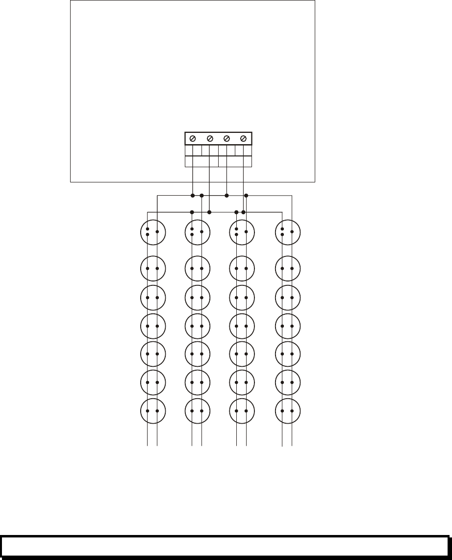
MX4428 MXP Engineering / Technical Manual Document: LT0273
Analog Loop Design Considerations
Page 4-6 24 March 2006 Issue 1.5
MXP
MX DETECTOR LOOP
AL AR
+VE +VE
-VE -VE
S
P
U
R1
S
P
U
R2
S
P
U
R
3
S
P
U
R4
4 Isolator
Bases
(with or without
detectors)
L1 L1 L1 L1
MMM M
L2 L2 L2 L2
L
L
L
L
L
L
L
L
L
L
L
L
L
L
L
L
L
L
L
L
L
L
L
L
L1
L1
L1
L1
L1
L1
L1
L1
L1
L1
L1
L1
L1
L1
L1
L1
L1
L1
L1
L1
L1
L1
L1
L1
Universal Bases
,
Sounder Bases,
Relay Bases
NOTE : Total cable length < 2000m
Figure 4.2 STAR CONNECTION ON MXP
4.3 CABLE SELECTION CONSIDERATIONS
Selection of cable to implement the Analogue Loop requires specification of .....
(i) CABLE TYPE
(i.e. construction and choice of materials)
This is determined from consideration of .....
MECHANICAL - For instance, does the application
REQUIREMENTS specification, or prevailing standards, call for
fire rated, armoured, etc.

Document: LT0273 MX4428 MXP Engineering / Technical Manual
Analog Loop Design Considerations
Issue 1.5 24 March 2006 Page 4-7
ELECTRICAL - Different construction/materials give different
REQUIREMENTS AC characteristics, noise immunity, etc.
(ii) CABLE WEIGHT
(i.e. gauge of wire used)
MECHANICAL- Does the application
REQUIREMENTS specification, or prevailing standards, call for a minimum gauge
(AS1670.1 specifies a minimum of .75mm² standard, for
instance).
ELECTRICAL - What is the minimum gauge wire that can be
REQUIREMENTS used without exceeding the maximum voltage drop for the
number of devices over the required loop length.
The four areas to be considered therefore are
• AC requirements
• DC requirements
• Mechanical requirements
• Noise immunity
4.4 AC REQUIREMENTS
4.4.1 GENERAL
All common types of wiring with a total length of up to 2000m may be used. Refer to section
3.2.3.
4.5 DC CONSIDERATIONS
4.5.1 GENERAL
A maximum voltage drop of 17V is allowed on the cable from the MXP to the most distant
device. This applies both where
• the cable is driven from the “left” end only.
• the cable is driver from the “right” end only.
Refer to the calculations in section 3.2.2.
4.6 MECHANICAL CONSIDERATIONS
Electrical considerations aside, the system design should take into account mechanical
aspects such as .....
• Need for fire rated cable.
• Need for mechanical protection.

MX4428 MXP Engineering / Technical Manual Document: LT0273
Analog Loop Design Considerations
Page 4-8 24 March 2006 Issue 1.5
4.7 NOISE CONSIDERATIONS
Although the MXP loop has been designed for minimum electrical interference, it is still
capable of both picking up and generating electrical interference. The longer the loop the
greater the potential problems. Each analogue loop must be considered on its own merits,
taking into account possible noise sources along the loop's proposed routing. Normal
engineering practice applies, such as keeping the loop wiring separate from other wiring,
especially power cables, speaker cables, leaky coaxial cable and noise sensitive cables for
audio systems.
In extreme cases it may be necessary to implement the analogue loop as a screened pair,
with the screen connected to the metal case at the MXP only.

Document: LT0273 MX4428 MXP Engineering /Technical Manual
MXP Current Consumption
Issue 1.5 24 March 2006 Page 5-1
CHAPTER 5
MXP CURRENT CONSUMPTION

MX4428 MXP Engineering / Technical Manual Document: LT0273
MXP Current Consumption
Page 5-2 24 March 2006 Issue 1.5
5.1 THEORY
The MXP current consumption is considerably higher than that of the other responders (even
higher than the MPR, in fact it can be considerably higher than the MPR depending on the
sounder load). It must be carefully considered when engineering the MX4428 responder
loop.
Use of the F4000CAL PC program is strongly recommended as it performs the following
calculations automatically.
A formula for predicting the MXP current is.....
I(mA) = (ITOT(mA) * (40V / VIN) * ( 1 / PCE) ) + (IQ(mA) * (24V / VIN))
Where .....
PCE = Power converter efficiency = 0.80
IQ = MXP quiescent current at 24V = 50mA.
ITOT = Total current sourced into the AL and AR terminals, which can
be calculated as shown in Section 3.2.2
VIN = MX4428 Responder Loop voltage
5.1.1 ALARM CURRENT
The alarm current calculated for all responders can be calculated and used to ensure that
1) The total current to be sourced from the MX4428 does not exceed 2.0A
2) No responder will see a supply voltage of less than 17V, allowing for the minimum
battery voltage at the MX4428 and voltage drops in the responder loop wiring.
Once MXP currents are calculated, the voltage drops around the responder loop can be
calculated. This will give a more accurate figure for the operating voltage of each MXP which
will result in a slightly different current consumption. The full calculation is an iterative
process when performed manually, and it is recommended that the PC program F4000CAL
is used.
Taking the example from section 3.2.5, where the alarm current was calculated at 221mA,
the MXP supply current at (22V) will be
I(mA) = (ITOT(mA) * (40V / VIN) * ( 1 / PCE) ) + (IQ(mA) * (24V / VIN))
= (221 * (40 / 22) * (1 / 0.8)) + (50 * (24 / 22))
= 502mA + 55mA
= 557mA.
This current, together with the load of other responders on the MX4428 responder loop, can
be used to calculate the voltage drops on the responder loop power wiring, and possibly
refine the value used for the MXP supply voltage (22V above). The calculations can be
performed iteratively until little change is evident.
Document: LT0273 MX4428 MXP Engineering /Technical Manual
MXP Current Consumption
Issue 1.5 24 March 2006 Page 5-3
It is of interest to recalculate the current consumption assuming for example the supply
voltage is only 17.0V (the minimum operating voltage of the MXP). In this case the
consumption is increased to 721mA. It can be seen that if the responder loop power wiring
has too much resistance, the voltage to the responders is reduced by their current
consumption, which results in them requiring even more current and compounding the
problem.
5.1.2 QUIESCENT CURRENT
The quiescent current of all responders can be calculated and used to ensure there is
enough battery capacity and supply current at the MX4428.
The quiescent current for the MX loop is calculated as in section 3.2.2, but using the
quiescent current instead of the alarm current. Then the MXP supply current can be
calculated as described in section 5.1. Once again iterative calculations may be required to
adjust for the responder loop voltage drop.
5.1.3 HEAT LOSS
The heat loss from the MXP PCB can be calculated as follows –
W = ITOT(mA) * 40V * ( 1 - PCE) / PCE + IQ(mA) * 24V
Where .....
W = Heat loss in milliwatts
PCE = Power converter efficiency = 0.80
IQ = MXP quiescent current = 50mA at 24V.
ITOT = Total current sourced into the AL and AR terminals, which can
be calculated as shown in Section 3.2.2
Using the above figures, the equation simplifies to
W(mW) = ITOT(mA) * 10V + 1200mW
This can be calculated separately for quiescent and alarm conditions, depending on whether
quiescent or alarm figures are used to calculate IQ.
The maximum possible heat loss is 5.2 watts.
MX4428 MXP Engineering / Technical Manual Document: LT0273
MXP Current Consumption
Page 5-4 24 March 2006 Issue 1.5
THIS PAGE INTENTIONALLY LEFT BLANK

Document: LT0273 MX4428 MXP Engineering / Technical Manual
Event Log and Status at MX4428
Issue 1.5 24 March 2006 Page 6-1
CHAPTER 6
EVENT LOG AND STATUS AT MX4428

F4000 MXP Engineering / Technical Manual Document: LT0273
Event Log and Status at MX4428
Page 6-2 24 March 2006 Issue 1.5
6.1 RETURNED ANALOG VALUES
The MXP returns up to 4 different analog values per device - CV, TV, HH, and HL. The
following table details what each value means for each device type.
Type CV TV HH HL
814H Temperature
Current Value ROR History High
of Temperature SLV History High of
ROR SLV
814PH Smoke CV Smoke TV HH percent*
(max% of Temp SLV,
Temp ROR SLV,
Smoke SLV)
Temp CV
814CH CO CV CO TV HH percent*
(max% of Temp SLV,
Temp ROR SLV,
CO SLV)
Temp CV
814I Current Value Tracked Value History High of SLV History Low of
SLV
MIM800 analog i/p – History High History Low
MIM801 analog i/p – History High History Low
CP820 analog i/p – History High History Low
CIM800 analog i/p 1 analog i/p 2 Hist High (both) Hist Low (both)
DIM800 analog i/p 1 analog i/p 2 Hist High (both) Hist Low (both)
SNM800 EOL Supervision Supply
Supervision History High EOL
Supervision History Low EOL
Supervision
LPS800 Analog i/p 0
(while not
operated)
Analog i/p 1
(while not
operated)
History High of analog
i/p 0 (while not
operated)
History Low of
analog i/p 0 (while
not operated)
RIM800 – – – –
VLC800 Current Value Fixed at 12 History High %* 0
*HH percent will indicate whichever of Temperature, Rate of Rise, or Smoke/CO has been
highest, in terms of the percentage of its alarm threshold. It will be rounded to the nearest
5%, and the last digit will indicate which type it represents. A last digit of 0 or 5 indicates
smoke or CO. A last digit of 1 or 6 indicates temperature, and a last digit of 2 or 7 indicates
temperature rate of rise.
For example, 51 will indicate that temperature has been highest at 48-52% of the alarm
threshold. 65 will indicate smoke/CO has been highest, at 63-67% of the alarm threshold.
For temperature 20°C will be 0% and the alarm limit 100%.
All History High and History Low values (where used as maximum and minimum) will be
based on Step Limited values i.e. the same values as are used for alarm comparison.
However note that PreAlarm comparisons are performed using “CV”, i.e. values without Step
Limited filtering. Therefore a PreAlarm may occur even though the “History High” value is
less than the PreAlarm Threshold.

Document: LT0273 MX4428 MXP Engineering / Technical Manual
Event Log and Status at MX4428
Issue 1.5 24 March 2006 Page 6-3
6.2 FAULT AND ALARM EVENT LOG
The table below lists examples of event log items which are produced at the MX4428 panel.
Circuit / point event logging must be enabled to see the events listed below. Zone events are
not shown.
Event on MXP Event Logged Event Logged on return to
normal
Database tx from F4000
to MXP
R
SP 1 DATABASE TX
START
RSP 1 DATABASE TX
COMPLETE
Point Alarm CCT 1/1 ALARM
PNT 1/30 ALARM
CCT 1/1 ALARM CLR
PNT 1/30 ALARM CLR
Point Fault CCT 1/1 FAULT
PNT 1/20 FAULT
PNT 1/20 FAULT CLR
CCT 1/1 NORMAL
Point Pre-Alarm PNT 1/3 PRE-ALARM PNT 1/3 ALARM CLR
SNM800 wiring o/c or
s/c RLY 1/1 FAULT
PNT 1/26 SUPERVISION
FAULT
PNT 1/26 NORMAL OFF
RLY 1/1 NORMAL
SNM800 Supply Fail RLY 1/1 FAULT
PNT 1/26 LOAD SUPPLY
FAIL
PNT 1/26 NORMAL OFF
RLY 1/1 NORMAL
SNM800 / RIM800
checkback fail RLY 1/1 FAULT
PNT 1/24 CONTROL CB
FAIL
P
NT 1/24 CONTROL CB NML
(RIM800)
P
NT 1/26 NORMAL ON (or OFF)
(SNM800)
RLY 1/1 NORMAL
DIM800 Supply Low CCT 1/1 FAULT
PNT 1/25 FAULT
PNT 1/25 LOAD SUPPLY
FAIL
PNT 1/25 FAULT CLR
CCT 1/1 NORMAL
Point scan fail PNT 1/22 NODE FAIL
CCT 1/1 FAULT
PNT 1/22 NODE FAIL CLR
CCT 1/1 NORMAL
Detector calibration fault CCT 1/1 FAULT
PNT 1/2 FAULT
PNT 1/2 PARAMETER
ERROR
CCT 1/1 NORMAL
PNT 1/2 FAULT
Loop o/c RSP 1 LOOP OPEN
CIRCUIT
RSP 1 LOOP OPEN CIRCUIT
CLEARED
Loop line A or B short or
overload RSP 1 LOOP SHORT
CIRCUIT
RSP 1 LOOP SHORT CIRCUIT
CLEARED
Type Mismatch PNT 1/1 POINT TYPE
MISMATCH
PNT 1/1 POINT TYPE OK
Foreign Device PNT 1/3 FOREIGN DEVICE (note- re-logged after DP command)
System Test or autotest
- device not normal at
start
PNT 1/2 TEST START NOT NML
CCT 1/1 FAIL SELF TEST 3 1
System Test or autotest
- device alarm test fail PNT 1/1 ALARM TEST FAIL
CCT 1/1 FAIL SELF TEST 3 1
Zone alarm test device
fail PNT 1/1 ALARM TEST FAIL
Diagnostic Pollscan result -Correct point found P1/22 LINE 1 OK LINE 2 OK LED OFF
TYPE OK
Diagnostics Pollscan result - point not found P1/100 LINE 1 FAULT LINE 2 FAULT LED
OFF TYPE OK
Diagnostic Pollscan result -Type mismatch P1/20 LINE 1 OK LINE 2 OK LED OFF
TYPE BAD
Note “Type Mismatch” means a different device type was found at an address, from the type
programmed in the panel configuration for that address. An example of this would be a
MIM800 found at an address that is configured to have an 814PH. Refer to section 3.1.1 for
details of some device substitutions that are accepted without generating a fault.
F4000 MXP Engineering / Technical Manual Document: LT0273
Event Log and Status at MX4428
Page 6-4 24 March 2006 Issue 1.5
THIS PAGE INTENTIONALLY LEFT BLANK

Document: LT0273 MX4428 MXP Engineering / Technical Manual
MXP Technical Description
Issue 1.5 24 March 2006 Page 7-1
CHAPTER 7
MXP TECHNICAL DESCRIPTION

MX4428 MXP Engineering /Technical Manual Document: LT0273
MXP Technical Description
Page 7-2 24 March 2006 Issue 1.5
7.1 GENERAL
The MXP has two major functions:
(i) To provide an interface to an MX4428 responder (communications/power) loop, via
which data gathered by the MXP may be transferred to the MX4428 Master for
display, annunciation, and processing as appropriate.
(ii) To provide an interface to the Analogue Loop. Data retrieved from the devices
connected to the Analogue Loop is processed to determine the ALARM/NORMAL/
FAULT status of each device, and this data is passed on to the MX4428 Master via
the MX4428 Loop Interface. The Analogue Loop interface also allows outputs to be
sent to those devices that support them, to initiate device tests, activate relays, etc.
The MXP is implemented as one printed circuit board (1901-213).

Document: LT0273 MX4428 MXP Engineering / Technical Manual
MXP Technical Description
Issue 1.5 24 March 2006 Page 7-3
7.2 CIRCUIT DESCRIPTION
7.2.1 BLOCK DIAGRAM
A block diagram of the MXP is given in Figure 7.1.
The MXP can be divided into 4 sections:
(i) The microprocessor and memory. This is the "heart" of the MXP.
(ii) The power supply. The power supply produces the 40V isolated supply for the
Analogue Loop and also the 5V isolated supply for the microprocessor.
(iii) The MX4428 Loop Interface. The Loop Interface contains the connect, disconnect
circuitry for the MX4428 Loop Power Supply and also the serial data driver circuits.
(iv) The Analogue Loop Interface. This section contains the Loop Driver/ Receiver circuit
and the Loop Isolator circuits.
7.2.2 MICROPROCESSOR & LOGIC CIRCUITRY
The MXP is controlled by the 68302 Microprocessor CPU (U1). Connected to the CPU bus
is the FLASH (U2) which contains the MXP software, and the RAM (U3 and U4) which is
used for storing parameters and data associated with devices on the Analogue Loop.
The 68302 includes a communications processor with 3 serial ports. These are used for the
2 responder loop ports and a diagnostic port.
To reduce the number of components on the PCB, a PAL (Programmable Array Logic) (U5)
is used to generate bus signals such as RD-, L WR-, and U WR-. It also drives the status
LED and is used to read some of the DIP switches.
Both the FLASH (U2) and PAL (U5) are factory programmed for use in the MXP. However
the FLASH (U2) can easily be reprogrammed in the field.
7.2.2.1 Power On Reset & Watchdog Circuits
The power on reset consists of the DS1232 (U6), which drives the RST signal to the CPU
low when the 5V supply is below 4.6 Volts. This ensures that the CPU does not corrupt the
RAM when the 5V supply collapses, and the CPU starts up reliably when the 5V supply turns
on. The DS1232 also includes a Watchdog circuit inside, to produce a RESET if the CPU
stops running properly.
7.2.2.2 Memory
Memory addresses are decoded by the MC68302. When first powered up the FLASH
occupies the bottom 8k bytes. However the software relocates the FLASH so that the
memory addressing is as follows -
000000 - 03ffff RAM
400000 - 47ffff FLASH
800000 - 80000f LED and SWITCHES via PAL
f00000 - f00fff INTERNAL RAM AND PERIPHERALS
The RAM memory and PAL chip are powered by the +5VB supply, which has a supercap
(C68) to supply power when the MXP is powered down. This allows the MXP to retain its
RAM memory contents for typically 10 hours on MXP power down.
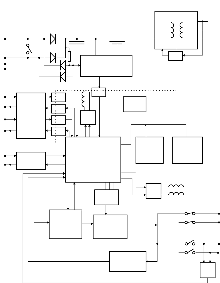
MX4428 MXP Engineering /Technical Manual Document: LT0273
MXP Technical Description
Page 7-4 24 March 2006 Issue 1.5
68302 CPU /
Comms Processor
RAM
64kb / 256kb FLASH
256kb / 512kB
Data / Address
Watchdog /
Reset
Generator
Line Drivers /
Receivers
CHNL1
CHNL2
opto
coupler
opto
coupler
opto
coupler
opto
coupler
opto
coupler
opto
coupler
Connect / Disconnect
24V IN
24V OUT
+VS+V
MIN V
0V
0V IN
0V OUT
0V
0V
Disconn In -
RL3
RL3
Switching PSU
+40V ISO
+5V ISO
0V ISO
Feedback
Latching
Relay
Drive
Isolation Barrier
RESPONDER
LOOP
Pseudo RS232
Interface
Diagnostic
Port
Overcurrent
Detector /
Shutdown
5 bit D/A
Convertor
Modulator
40V ISO
Analog
(NOSEx
)
Loop
Left
Right
0V ISO
0V ISO
Receive
Discriminator
Nosex RX
AD1..5
RL1
RL2
40VReset Overload - Relay
Drive
RL1
RL2
Sense
Return Fault
R90
U10
Q17
U11
OC6
Q22
U7C, U7D
OC5
U8
D36
D44
D37
D35
C65.C66
U7A
Q18, Q20
U7B
Q19, Q20
OC1
OC3
OC2
OC4
U6
U1
U3, U4 U2
Q5, Q6
R76-R82
Q14, Q15
Q12, Q2, Q1,
Q4, Q13
Q3, U13A
OC7
MICROPROCESSOR and MEMORY
POWER SUPPLY
ANALOG LOOP INTERFACE
RESPONDER LOOP INTERFACE
Figure 7.1 MXP Block Diagram
7.2.3 MXP POWER SUPPLY
The raw power to the board is supplied from the 24VIN terminal (via D36) or the 24VOUT
terminal (via D34), or both, depending on the Loop conditions.
This voltage "+V" is smoothed and maintained by reservoir capacitors C65, C66, and C71,
which store sufficient charge to maintain the circuitry under transient loop fault conditions.
From "+V" the following supplies are derived:
Document: LT0273 MX4428 MXP Engineering / Technical Manual
MXP Technical Description
Issue 1.5 24 March 2006 Page 7-5
(i) +VS This is a switched version of "+V", which is switched OFF
when the loop supply falls below the voltage required for
correct operation of the MXP.
(ii) 40V ISO A regulated, isolated 40V supply used to drive the Analogue
Loop circuitry and addressable devices.
(iii) 24V ISO Derived from 40V ISO to power 24V relays.
(iv) 5V Used to power the CPU and logic circuitry.
(v) 5VB Used to power the RAM and PAL. Backed up by supercap
(C68).
Descriptions of the circuitry required to generate these power supplies follow.
7.2.3.1 +VS Circuitry
The MXP is specified to operate over an MX4428 loop supply range of 17.0V to 30.0V. The
MX4428 loop fault clearing technique relies on the fact that responders that are not powered
up "look like" a high impedance (see Section 7.2.4 for details). The circuitry is therefore
divided up into two sections, a (relatively) high current portion which becomes active only
when adequate voltage is available, and a low current portion that is continuously powered
up and whose sole purpose is to sense the loop voltage and control the enabling/disabling of
the high current circuitry. Loop voltage sensing is performed by comparator U7:C and
associated components which, in turn, operate power switch Q22 to feed +VS. Since the
voltage regulator draws peak currents up to around 5A, a FET is used for Q22, which gives a
low voltage drop for minimal control (gate) current.
D39, R12, R35, R113 ensure that +VS becomes active if the loop supply exceeds 17.0V,
with R28, R110, D38 providing about 4V of hysteresis (i.e. once switched on +VS will stay
switched on until the supply voltage drops below 13V).
7.2.3.2 40V ISO
The 40V ISO and 5V ISO supplies are produced using the switch mode power supply
controller IC U10, FET Q17, and associated components. The circuit configuration is such
that the circuit operates in flyback mode, energy being stored in L1 primary during Q17's ON
period and transferred to the two secondary windings during the OFF period.
The current into the diode of optocoupler OC6 increases rapidly as the 40V ISO voltage
passes through 40V (adjustable by means of VR1). The optocoupler OC6 controls the
feedback to U10 pin 2 which adjusts the duty cycle of the current pulses into L1's primary
and maintains regulation of 40V ISO.
R6 and C63 provide stability, essentially coupling the sawtooth from the internal oscillator to
the comparator – input, thereby making the + input a much lower gain pulse width control
than it would otherwise be. R107, R65, C38 provide over-current protection, while C34
defines the frequency of oscillation (approximately 80KHz). D41 and C77 provide a “soft
start” circuit to reduce the current taken during the startup time.
7.2.3.3 24V ISO
The 40V ISO voltage is regulated by a linear regulator consisting of Q23, D40 and
associated components. This supply is only required to supply a low current (about 30mA
max) to drive relays. The reference diode (D40) used for the 24V supply is also used as the
reference for the 40V supply.
MX4428 MXP Engineering /Technical Manual Document: LT0273
MXP Technical Description
Page 7-6 24 March 2006 Issue 1.5
7.2.3.4 +5V ISO & +5V Batt
A second L1 secondary winding is used to produce an 8V supply, This 8V supply is poorly
regulated and may vary from 7.5V to 10V depending on the 40V ISO load. The 8V supply is
regulated by U11 to 5.2V.
This supply is then passed through D32 to produce the 5V supply for the CPU and logic
circuitry. The 5.2V supply also passes through D31, to produce +5V Batt, and this supply
contains a supercap (C68) which is used to keep this supply up after the power supply has
shutdown. R66 is used to limit the charge current to the supercap. This supply is used to
power the RAM on the MXP, and retain its contents during short (up to a few hours) power
downs.
7.2.4 MX4428 LOOP INTERFACE
7.2.4.1 Loop Disconnect Circuitry
The MXP, like all MX4428 compatible Responders, includes a DISCONNECT relay (RL3)
which is used to isolate shorts on the power supply loop.
Normally 24V power passes from one Responder to the next via the 24VIN terminal /
DISCONNECT relay / 24 VOUT terminal path, supplying power to the Responder on the way
through. D35, D37, R90 form a diode gate such that a loop short on either 24VIN or
24VOUT applies a low voltage to comparator U7:D. This generates a DISCON IN- signal to
the microprocessor which then opens the DISCONNECT relay to isolate the fault.
Depending on the time taken for the shorted section to be isolated, the power output of the
MX4428 panel may collapse completely, removing power from all responders. Therefore it is
necessary for them to respond rapidly to the DISCON IN signal and open the DISCONNECT
relay in their last dying gasps before their power supplies collapse to zero.
Generally, all Responders on the loop respond in like fashion and break the loop supply.
(Depending on the position of the short, and loop resistances, some may not open their
DISCONNECT relays.) Starting from the Responder nearest the MX4428 Master, each
Responder then makes a decision, based on the value of “MIN V” (refer to Figure 7.1)
whether to re-connect the relay or not. If MIN V is less than +V/2, the loop fault is on one of
its 24V terminals, so it will not re-close its DISCONNECT relay. If, however, MIN V is
greater than +V/2 the fault lies beyond the next Responder and it can therefore apply power
to that Responder.
The newly powered up Responder then makes a similar decision, followed by each
successive Responder up to the Responder with the loop fault on its far side which will not
close its DISCONNECT relay.
Similarly Responders on the other end of the Responder loop will close their DISCONNECT
relays, up to the Responder connecting to the section of the loop with the short circuit.
With a single short circuit, all responders will eventually be powered up (receiving power
from one end of the loop or the other), however the two responders on either side of the
short will have their DISCONNECT relays open.
7.2.4.2 Disconnect Relay Driver
U8A and U8B with Q10 and Q11 form a bridge circuit to drive DISCONNECT relay RL3.
This is a magnetically latched relay to save power consumption. Its position can be switched
by providing a short pulse of voltage, with the polarity of the voltage controlling the position.
Document: LT0273 MX4428 MXP Engineering / Technical Manual
MXP Technical Description
Issue 1.5 24 March 2006 Page 7-7
In response to DISCON IN– going low, the microprocessor outputs a 10 msec pulse to
DISCON OUT+, which applies “0V” to RL3 pin 16 through D5 and U8 pin 2, and “+24V”
through Q11 to RL3 pin 1, thereby setting the relay contacts to their open state. When
DISCON IN+ goes low the microprocessor outputs a 10 msec pulse to CONOUT, which
applies “0V” to RL3 pin 1 through D6 and U8 pin 1, and “+24V” through Q10 to RL3 pin 16,
thereby re-setting the relay contacts to the closed state.
The DISCON IN– signal is configured as an interrupt signal to the CPU. This allows a very
fast response to it going low and ensures the relay is opened immediately. This is necessary
as a short anywhere on the responder loop will often result in the responder power
collapsing completely and the relay must be opened while sufficient charge remains in
capacitors C64, C65, C66, and C59-C62.
When neither DISCON OUT+ nor CONOUT is high, no power is applied to the coil of RL3.
7.2.4.3 MX4428 Communications Circuitry
The duplicated MX4428 communications channels are implemented using serial ports 1 and
2 of the 68302 CPU. The two transmit lines are isolated with optocouplers and buffered with
Darlington drivers. The receive circuits are protected with series resistors and shunt
diodes/capacitors, digitised with comparators, and isolated with optocouplers.
Passing messages around the loop is done entirely with software. For details of the MX4428
responder protocol and loop operation, refer to “F4000 Technical Manual - Appendix C,
Responder Communication Protocol”.
7.2.5 ANALOGUE LOOP INTERFACE
The Analog Loop (also known as MXP loop or NOSEx loop) is a two-wire circuit with the
MXP being the master and up to 200 addressable devices which are slaves.
The MXP supplies the loop power (36 - 39V dc) which powers the addressable devices and
sounder outputs. The loop + voltage is modulated with a 4V p-p dual frequency sinewave in
order to transmit data using the power wire.
Both the MXP and the addressable devices transmit and receive in the same way. The
addressable devices normally only transmit immediately after they have been polled by the
MXP, however in special circumstances they can transmit interrupt messages when they
have something urgent to send.
An example of a message on the loop is shown in Figure 7.2.
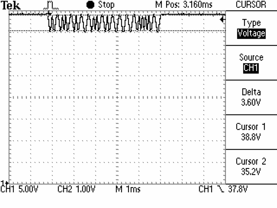
MX4428 MXP Engineering /Technical Manual Document: LT0273
MXP Technical Description
Page 7-8 24 March 2006 Issue 1.5
Figure 7.2 Analog Loop Typical DC Level and Data Waveform
7.2.5.1 Over-Current Protection
The current drawn by the analog loop passes through current sense resistors R22 - R26.
When the voltage across these resistors exceeds approximately 0.65 volts (corresponding to
a current of just over 400mA), the collector of Q2 begins to conduct. Thermistor RV3 and
resistor R119 compensate for the fact that the VBE threshold voltage of Q2 varies with
temperature. Q2 conducting pulls the gate of Q12 to +40V and switches off Q12. The drain
of Q12 then drops to around 5V or less depending on the load on the analog loop. Q13 is
then turned on by the current through R5. Q13 then holds Q12 off even though the overload
is now gone and Q2 is no longer conducting.
This “latched” over-current situation can only be reset by the CPU. The CPU senses the
absence of 40V through the sense resistors R68 and R67 and the signal OVERLOAD–
going to a logic low. The CPU (periodically) tries to reset the over-current latch by applying a
short (approx 5 ms) pulse to “40V RESET”. This pulse turns on Q4 and Q1, which turns off
Q13. Q12 will then turn back on and stay hard on as long as there is no over-current.
For the duration of this 5 ms pulse, the latching action of the circuit is disabled, and Q12 will
act as a linear current limiter. During this time the dissipation in Q12 can be up to 40V *
400mA i.e. 16 watts. This will be an excessive dissipation for Q12 if it continues indefinitely,
which is why the reset pulse is limited to 5 ms, and indeed why the latching action is required
in the first place.
Document: LT0273 MX4428 MXP Engineering / Technical Manual
MXP Technical Description
Issue 1.5 24 March 2006 Page 7-9
7.2.5.2 Data Transmission
Each bit transmitted consists of single cycle of a sinewave of one frequency for a ‘0’ and
another frequency for a ‘1’. Each cycle is made up from a number of discreet samples, with a
5uS spacing between samples. For each sample the digitised value is output on the 68302
CPU onto signals AD1, AD2, AD3, AD4, and AD5. These signals are converted to an analog
voltage “TXDATA” by resistors R72, R73, R74, R75, R76, R77, R82, R81, R80, and R79,
which form a conventional R/2R ladder. Resistor R78 adds a DC offset of about 1.5V to the
TXDATA voltage.
Transistor Q14 is a current sink with the current controlled by the TXDATA voltage. The
varying current develops an AC voltage of 4V p-p across R85. This AC voltage is coupled
onto the gate of Q15 through C53. Q15 provides the DC power for the loop (R85 is too high
a resistance for this purpose). Q15 is a source follower, and its source follows the voltage on
its gate. The circuit of R85, Q15 and associated components can be viewed as a circuit with
about 2 - 4 volts DC drop (at 0 - 400mA load), but which has a high AC impedance
determined by R85. (Somewhat like an inductor in that it has a low DC resistance but high
AC impedance.) This supplies power to the loop but at the same time allows the MXP
transmitter (Q14) and the transmitters in the addressable devices to modulate the voltage for
data transmission.
7.2.5.3 Data Reception
The data on the analog loop is filtered by L9, L10, C30, R32, R33 and C39. C37 provides
DC blocking. D2 and D3 with C40 clamp the incoming voltage to 1.2V p-p. The filtered,
clamped voltage is amplified by Q3 and then sliced by U13A to form a 0 - 5V square wave
from the incoming sinewave. The received data is decoded into 0s and 1s by timing and
software within the CPU. Note that the slice level is about 0.6V from the peaks of the AC
voltage on the loop and not at the mid point of the AC component.
7.2.5.4 Open Circuit Fault Handling
The loop is normally driven from the AL terminals, and not driven by the AR terminals.
Optocoupler OC7 checks that power is reaching the far end of the loop i.e. the AR terminals.
If this is not the case, the CPU will close relay RL2 so that the loop is driven (power and
data) from both ends. Thus a single open circuit will result in all addressable devices still
receiving power and still being able to communicate with the MXP. Two open circuits may
result in loss of power and communications with some devices.
Periodically (every 30 seconds) when the loop is driven from both ends, the CPU will open
the right end relay to check whether the open circuit fault has gone away.
7.2.5.5 Short Circuit Fault Handling
If the CPU finds that the over-current detector described in section 7.2.5.1 is unable to be
reset or is operating repeatedly in a short time, it will try to drive the loop from one end at a
time in case the short is present only when driving from one end of the loop. In this case it
will drive the loop from the other end only. However it will try the faulty end very briefly once
every 30 seconds to see if the fault has gone away.
Note that if there are no isolator bases in the loop, the short will appear from both ends and
all devices will be effectively disconnected.
If there are isolator bases, then after an initial overload which will be reset, the isolators will
isolate the section of the loop with the short. The loop will then appear to have an open
circuit and will be driven by both ends simultaneously as described in section 7.2.5.4. Only
those devices connected to the shorted section will be disconnected.

MX4428 MXP Engineering /Technical Manual Document: LT0273
MXP Technical Description
Page 7-10 24 March 2006 Issue 1.5
In the event that there are isolator bases installed, but there is a short on the section of loop
between the MXP and the first (or last) isolator, the MXP will detect the short and drive the
loop only from the opposite end. Every 30 seconds it will very briefly try reconnecting the
faulty end to see if the fault has gone away. This reconnection must be very brief (if the short
is still present), as it will cause the loop voltage to collapse, and the voltage must be restored
quickly enough so that the addressable devices retain enough charge in their power supply
filter capacitors and do not reset.
7.3 MXP ADJUSTMENTS
None of these adjustments should require changing in the field, unless PCB components
have been changed.
7.3.1 40V ISO SUPPLY VOLTAGE ADJUSTMENT
Disconnect all circuits from the analog loop terminals. Connect 24V to the responder loop
power terminals. Adjust VR1 so that the voltage measured between TP16 “40V ISO” and
TP15 “0V ISO” is 40.0V + / – 0.5V.
7.3.2 TX DATA VOLTAGE ADJUSTMENT
Disconnect all circuits from the analog loop terminals. Adjust VR2 so that the AC signal
voltage measured with an oscilloscope between TP3 “LINE” and TP15 “0V ISO” is 4.0V -
4.8V p-p.
Refer to Figure 7.2 for an example waveform. Note that that waveform was captured with an
analog loop and some addressable devices connected and so the measured voltage is
slightly less than that specified.
Note that the MXP will need to be connected to an MX4428 FIP, or standalone mode
activated, for any data to be transmitted.
7.3.3 40V ISO SUPPLY CURRENT LIMIT ADJUSTMENT
Disconnect all circuits from the analog loop terminals. Connect 24V to the responder loop
power terminals. Apply a slowly increasing load current to the loop terminals and check at
what current the overload circuit operates (i.e. current and voltage drop to zero before being
restored by the software - this may happen repeatedly). The overload should occur at a
current of 415mA to 430mA. If it is over this range snip out one of the resistors R22 - R25. If
it is under this range, re-insert one of these resistors (R22 and R23 are 22Ω and R24 and
R25 are 47Ω). Repeat the procedure as required.

Document: LT0273 MX4428 MXP Engineering / Technical Manual
MXP Technical Description
Issue 1.5 24 March 2006 Page 7-11
7.4 MXP LED INDICATIONS
The status LED (LD1) on the MXP board indicates the following conditions –
Indication Condition
2 quick flashes every 2
seconds The MXP is normal and polled by the MX4428 panel.
1 quick flash every 2
seconds The MXP is normal apart from NOT being polled by the
MX4428 panel.
7 flashes then a pause,
repeating.
Each of the 7 flashes
indicates a particular fault
is present when the flash is
long, or not present when
the flash is short.
1st flash : Device polling is stopped due to a configuration
download from the MX4428 panel.
2nd flash : One or more configured devices is not responding.
3rd flash : The MXP is not being polled by the MX4428 panel.
4th flash : The responder loop power relay has been opened
due to a short on one side of the MXP.
5th flash : The detector loop is open circuit.
6th flash : The detector loop is shorted on "left" terminals.
7th flash : The detector loop is shorted on "right" terminals.
Continuous very rapid
flashes The MXP has just powered up. This phase should only last a
couple of seconds.

MX4428 MXP Engineering /Technical Manual Document: LT0273
MXP Technical Description
Page 7-12 24 March 2006 Issue 1.5
7.5 PARTS LIST
PART NUMBER. DESCRIPTION QTY/ASSY REF DESIG
PA0893 PCB ASSY,1901-213,F4000 MXP RESPONDER
CA0001 CAP,CERAMIC,10P,50V 1.0000 C45
CA0002 CAP,CERAMIC,15P,50V 2.0000 C1 C2
CA0004 CAP,CERAMIC,68P,50V 1.0000 C63
CA0005 CAP,CERAMIC,100P,50V 1.0000 C39
CA0009 CAP,CERAMIC,2N2,50V 1.0000 C37
CA0010 CAP,CERAMIC,4N7,50V 2.0000 C69 C70
CA0013 CAP,CERAMIC,22N,40V 2.0000 C41 C42
CA0016 CAP,CERAMIC,47P,50V 1.0000 C43
CA0021 CAP,CERAMIC,1N,100V,P2.54MM 6.0000 C30 C31 C32 C35 C36
C38
CA0022 CAP,CERAMIC,10N,63V,P2.54MM 2.0000 C47 C48
CA0023 CAP,CERAMIC,MONOLITHIC,100N,50V,P2.54MM 23.0000 C3 C5 C6 C7 C8 C9
C10 C11 C12 C13 C14
C15 C16 C17 C18 C19
C20 C21 C22 C23 C24
C25 C26
CA0201 CAP,ELECTRO,RADIAL,1U,50V,D5mm,H12mm,P2mm 1.0000 C40
CA0202 CAP,ELECTRO,RADIAL,2U2,50VMIN,DXL 6.5 X12MM MAX 1.0000 C53
CA0206 CAP,ELECTRO,RADIAL,10U,63V MIN,6.5 x 12 MAX 5.0000 C49 C50 C51 C52 C77
CA0211 CAP,ELECTRO,RADIAL,100U,16V 1.0000 C67
CA0218 CAP,ELECTRO,RADIAL,220U,63V,D10.5MM,H22M,P5MM 4.0000 C59 C60 C61 C62
CA0235 CAP,ELECTRO,RADIAL,470U,35V,D10.5mm,H20mm,P5mm 3.0000 C64 C65 C66
CA0327 CAP,POLYESTER,10%,P5mm,L7.5xT2.5xH6.5mm,10N,100V 3.0000 C44 C54 C57
CA0328 CAP,POLYESTER,10%,P5mm,L7.5xT2.5xH6.5mm,100N,63V 3.0000 C27 C28 C29
CA0330 CAP,POLYESTER,10%,P5mm,L7.5xT2.5xH6.5mm,47N,63V 1.0000 C46
CA0331 CAP,POLYESTER,10%,P5mm,L7.5xT2.5xH6.5mm,1N,100V 1.0000 C34
CA0630 CAP,SUPER CAP,0.22F,5.5V 1.0000 C68
CA0634 CAP,POLYESTER,10%,P5mm,L7.5xT3.5xH8.0mm,10N,400V 1.0000 C72
CA0635 CAP,ELECT,330U,35V,LOW ESR,D10mm,P5mm,H16mm 1.0000 C76
CL0453 COIL,L453,F4000 MXP,ISOLATED PSU,RM8 CORE 1.0000 L1
CN0063 CONNECTOR,IC SOCKET,20 PIN 1.0000 U5
CN0151 CONNECTOR,MOLEX,41761-4,MALE 1.0000 J5
CN0360 CONNECTOR,TERMI-BLOCK,VERT,4.0sqmm,5mm,4 WAY 3.0000 J1 J2 J3
CN0475 CONNECTOR,HEADER,0.1",SIL,6mm PIN,2 WAY 1.0000 LK1
CN0476 CONNECTOR,HEADER,0.1",SIL,6mm PIN,3 WAY 1.0000 LK3
CN0543 CONNECTOR,MINI JUMP WITH TAG,3 AMP 2.0000 LK1 LK3
CR0019 CRYSTAL,16.000MHz,30pF,HC49/4H 1.0000 XT1
DD0003 DIODE,1N4004 5.0000 D7 D8 D9 D35 D37
DD0004 DIODE,1N5404 2.0000 D34 D36
DD0005 DIODE,1N4148 8.0000 D2 D3 D4 D5 D6 D38
D41 D43
DD0027 DIODE,ZENER,0W5,D2.5mm,P10mm,5%,8V2 1.0000 D15
DD0030 DIODE,ZENER,0W5,D2.5mm,P10mm,5%,12V 1.0000 D42
DD0042 DIODE,ZENER,1W0,D3.0mm,P10mm,5%,6V2 1.0000 D33
DD0059 DIODE,SCHOTTKY,BYV10-40,1A,40V 2.0000 D31 D32
DD0060 DIODE,BAT85,SCHOTTKY,200MA,30V 4.0000 D27 D28 D29 D30
DD0061 DIODE,ZENER,HIGH SURGE,3W2,D3.8mm,P10mm,5%,33V 4.0000 D20 D21 D22 D23
DD0062 DIODE,ZENER,1W0,D3mm,P10mm,5%,24V 1.0000 D40
DD0065 DIODE,ZENER,HIGH SURGE,3W2,D3.8mm,P10mm,5%,36V 1.0000 D50
DD0073 DIODE,ZENER,HIGH SURGE,3W2,D3.8mm,P10mm,5%,7V5 1.0000 D19
DD0080 DIODE,BIDIRECTIONAL SUPPRESSOR,BZW04-28B (OR -31B) 3.0000 D16 D17 D18
DD0087 DIODE,MUR115 2.0000 D24 D25
DD0100 DIODE,ZENER,HIGH SURGE,3W2,D3.8mm,P10mm,5%,47V 6.0000 D10 D11 D12 D13 D14
D26
HW0237 HARDWARE,TRACK PIN,T1565-01 17.0000 TP1 TP2 TP3 TP4 TP5
TP6 TP7 TP8 TP9 TP10
TP11 TP12 TP13 TP14
TP15 TP16 TP17
IC0135 IC,7805CT,VOLTAGE REGULATOR,5V 4%,1.5A,TO220 1.0000 U11
IC0258 IC,LM393,OP AMP,DUAL,PRECIS VOLTAGE COMPAR,LOW PWR 1.0000 U13
IC0305 IC,LM385BZ 2.5,MICROPOWER VOLT REF DIODE,2.5V,TO92 1.0000 D39
IC0319 IC,LP339,QUAD COMPARATOR,ULTRA LOW POWER,DIL 2.0000 U7 U8
IC0413 IC,DS1232LP,LOW POWER MICROMONITOR 1.0000 U6
IC0447 IC,LM3578AN,750mA SWITCHING REGULATOR,DIL 1.0000 U10
IC0500 IC,OPTOCOUPLER,SFH608-4,CTR 160% @ 1mA,DIL 7.0000 OC1 OC2 OC3 OC4 OC5
OC6 OC7
LD0021 LED,3MM,RED,HIGH BRIGHT 1.0000 LD1
NT0007 NUT,HEX,M3,ZP 1.0000 Q17
PA0899 PCB ASSY,1901-213,F4000 MXP RESPONDER SMD CMP ONLY 1.0000
PT0020 POT,CERMET,100E,TOP ADJ,1 TURN,SPECTROL,63P 1.0000 VR2
PT0045 POT,CERMET,20K,TOP ADJ,1 TURN,SPECTROL,63P 1.0000 VR1
RL0051 RELAY,OMRON G6BU-1114C,12VDC,LATCHING 1.0000 RL3
Document: LT0273 MX4428 MXP Engineering / Technical Manual
MXP Technical Description
Issue 1.5 24 March 2006 Page 7-13
RL0052 RELAY,OMRON G6A-274P-24VDC 2.0000 RL1 RL2
RR0001 RESISTOR,0.6W,1%,50PPM,D2.5mm,P10mm,1E00 1.0000 R84
RR0013 RESISTOR,0.6W,1%,50PPM,D2.5mm,P10mm,22E0 2.0000 R22 R23
RR0016 RESISTOR,0.6W,1%,50PPM,D2.5mm,P10mm,39E0 1.0000 R92
RR0017 RESISTOR,0.6W,1%,50PPM,D2.5mm,P10mm,47E0 2.0000 R24 R25
RR0022 RESISTOR,0.6W,1%,50PPM,D2.5mm,P10mm,120E 2.0000 R66 R85
RR0023 RESISTOR,0.6W,1%,50PPM,D2.5mm,P10mm,150E 1.0000 R93
RR0027 RESISTOR,0.6W,1%,50PPM,D2.5mm,P10mm,330E 2.0000 R32 R33
RR0029 RESISTOR,0.6W,1%,50PPM,D2.5mm,P10mm,470E 1.0000 R64
RR0032 RESISTOR,0.6W,1%,50PPM,D2.5mm,P10mm,820E 1.0000 R119
RR0033 RESISTOR,0.6W,1%,50PPM,D2.5mm,P10mm,1K00 4.0000 R16 R47 R63 R65
RR0034 RESISTOR,0.6W,1%,50PPM,D2.5mm,P10mm,1K20 3.0000 R100 R102 R120
RR0037 RESISTOR,0.6W,1%,50PPM,D2.5mm,P10mm,2K20 3.0000 R88 R89 R90
RR0038 RESISTOR,0.6W,1%,50PPM,D2.5mm,P10mm,2K70 2.0000 R8 R10
RR0041 RESISTOR,0.6W,1%,50PPM,D2.5mm,P10mm,4K70 1.0000 R91
RR0043 RESISTOR,0.6W,1%,50PPM,D2.5mm,P10mm,6K8 2.0000 R99 R101
RR0044 RESISTOR,0.6W,1%,50PPM,D2.5mm,P10mm,8K20 3.0000 R7 R9 R98
RR0045 RESISTOR,0.6W,1%,50PPM,D2.5mm,P10mm,10K0 23.0000 R48 R49 R50 R51 R52
R53 R56 R57 R58 R59
R60 R61 R62 R70 R71
R79 R80 R81 R82 R87
R115 R116 R117
RR0047 RESISTOR,0.6W,1%,50PPM,D2.5mm,P10mm,15K0 1.0000 R43
RR0048 RESISTOR,0.6W,1%,50PPM,D2.5mm,P10mm,18K0 3.0000 R67 R78 R94
RR0049 RESISTOR,0.6W,1%,50PPM,D2.5mm,P10mm,22K0 2.0000 R95 R104
RR0051 RESISTOR,0.6W,1%,50PPM,D2.5mm,P10mm,33K0 5.0000 R17 R18 R19 R20 R118
RR0053 RESISTOR,0.6W,1%,50PPM,D2.5mm,P10mm,47K0 1.0000 R54
RR0054 RESISTOR,0.6W,1%,50PPM,D2.5mm,P10mm,56K0 2.0000 R31 R86
RR0056 RESISTOR,0.6W,1%,50PPM,D2.5mm,P10mm,82K0 1.0000 R103
RR0057 RESISTOR,0.6W,1%,50PPM,D2.5mm,P10mm,100K 10.0000 R3 R4 R5 R6 R12 R14
R15 R21 R34 R69
RR0058 RESISTOR,0.6W,1%,50PPM,D2.5mm,P10mm,120K 3.0000 R112 R121 R122
RR0059 RESISTOR,0.6W,1%,50PPM,D2.5mm,P10mm,150K 5.0000 R27 R28 R29 R30 R36
RR0060 RESISTOR,0.6W,1%,50PPM,D2.5mm,P10mm,180K 2.0000 R68 R83
RR0061 RESISTOR,0.6W,1%,50PPM,D2.5mm,P10mm,220K 3.0000 R11 R123 R124
RR0062 RESISTOR,0.6W,1%,50PPM,D2.5mm,P10mm,270K 1.0000 R111
RR0065 RESISTOR,0.6W,1%,50PPM,D2.5mm,P10mm,470K 3.0000 R40 R41 R42
RR0069 RESISTOR,0.6W,1%,50PPM,D2.5mm,P10mm,1M00 4.0000 R45 R46 R125 R127
RR0071 RESISTOR,0.6W,1%,50PPM,D2.5mm,P10mm,1M50 1.0000 R126
RR0072 RESISTOR,0.6W,1%,50PPM,D2.5mm,P10mm,1M80 2.0000 R37 R38
RR0077 RESISTOR,0.6W,1%,50PPM,D2.5mm,P10mm,10M0 1.0000 R1
RR0085 RESISTOR,0.6W,1%,50PPM,D2.5mm,P10mm,1E80 1.0000 R26
RR0740 RESISTOR,0.25W,1%,100PPM,D2.5mm,P10mm,20K 6.0000 R72 R73 R74 R75 R76
R77
RR0767 RESISTOR,0.25W,1%,100PPM,D2.5mm,P10mm,62K0 1.0000 R113
RR0775 RESISTOR,0.25W,1%,330K ***** USE RR0063 ***** 2.0000 R35 R110
RR0802 RESISTOR,NETWORK,0.125W,5%,0.1" SIP,9 PIN,8+C,10K 1.0000 RN1
RR0803 RESISTOR,NETWORK,0.125W,5%,0.1" SIP,9 PIN,8+C,100K 1.0000 RN2
RR0810 RESISTOR,2W,5%,D4mm,P15mm,PR02,330E 2.0000 R108 R109
RR0862 RESISTOR,0.6W,1%,50PPM,D2.5mm,P10mm,1M21 1.0000 R39
RR0865 RESISTOR,0.25W,1%,2M20 ***** USE RR0073 ***** 1.0000 R44
RR0887 RESISTOR,THERMISTOR,NTC,0.5W,4K7,-4.9%/K,10% 1.0000 RV3
RR0918 RESISTOR,VARISTOR,130VAC,0.25W 1.0000 RV2
RR0926 RESISTOR,2.5W,10%,200ppm,D6.0mm,P22.5mm,0E03 1.0000 R107
SC0041 SCREW,MACHINE,PH POZI,M3 X 6MM,ZP 1.0000 Q17
SF0243 SOFTWARE, F4000 MXP RESPONDER, V1.00 PAL 1.0000 U5
SU0198 SUNDRY,CHOKE,RF,10%,D4.0mm,P15mm,2U2H,1A 2.0000 L9 L10
SU0204 SUNDRY,CHOKE,RF,10%,D4.0mm,P15mm,4U7H,820mA 7.0000 L2 L3 L4 L5 L6 L7 L8
SW0005 SWITCH,DIL,8P1T 1.0000 SW1
SW0155 SWITCH,PUSHBUTTON,PCB MOUNT,NO,6mm x 6mm,L=5mm 1.0000 SW2
TR0029 TRANSISTOR,BC550 8.0000 Q3 Q4 Q5 Q6 Q7 Q9
Q10 Q11
TR0031 TRANSISTOR,BC557B,PNP,50V,100mA,TO92 5.0000 Q1 Q2 Q8 Q13 Q16
TR0049 TRANSISTOR,MPSA13/14,NPN DARL,30V,0.5A,0.5W,TO92 2.0000 Q18 Q19
TR0074 TRANSISTOR,MPSA63 2.0000 Q20 Q21
TR0075 TRANSISTOR,MTP2955E,MOSFET,P CH,60V,8A,40W,TO220 2.0000 Q12 Q22
TR0083 TRANSISTOR,BST72A,MOSFET,N CH,80V,300MA,.83W,TO92 1.0000 Q24
TR0084 TRANSISTOR,TIP110,NPN DARL,60V,2A,TO220 2.0000 Q14 Q23
TR0085 TRANSISTOR,HEATSINK,TO220,VERTICAL,17degC/W 1.0000 Q17
TR0094 TRANSISTOR,MTP12N10,MOSFET,N CH,100V,12A,79W,TO220 1.0000 Q17
TR0095 TRANSISTOR,RFP15N05L,MOSFET,N CH,15A,50V,60W,TO220 1.0000 Q15
WA0026 WASHER,CRINKLE,STAINLESS STEEL,M3 1.0000 Q17
IC0392 IC,MC68302FC16,uP,132 P PQFP,16MHz,68000+SERIAL PR 1.0000 U1
IC0429 IC,62256,32K X 8 SRAM,70ns,SMT 28PIN SOP,LOW POWER 2.0000 U3 U4
PB0893 PCB BARE,1901-213,F4000 MXP RESPONDER 1.0000
SF0242 SOFTWARE, F4000 MXP RESPONDER, V1.00 FLASH BOOT 1.0000 U2
MX4428 MXP Engineering /Technical Manual Document: LT0273
MXP Technical Description
Page 7-14 24 March 2006 Issue 1.5
THIS PAGE INTENTIONALLY LEFT BLANK

Document: LT0273 MX4428 MXP Engineering / Technical Manual
MXP Diagnostic Terminal
Issue 1.5 24 March 2006 Page 8-1
CHAPTER 8
MXP DIAGNOSTIC TERMINAL

MX4428 MXP Engineering /Technical Manual Document: LT0273
MXP Diagnostic Terminal
Page 8-2 24 March 2006 Issue 1.5
8.1 MXP DIAGNOSTIC TERMINAL OPERATION
8.1.1 INTRODUCTION
The MXP provides diagnostic functions via its serial port (J5) with a terminal or PC
connected. Commands may be entered which :
• Display the analogue values (Raw values, Filtered values, etc) of selected devices.
• Select devices for such display.
• Display and reset error counters.
• Determine all the devices and their types, as seen from each end of the loop.
• Change an addressable device’s address.
• Perform advanced diagnostics.
The MXP diagnostic serial port operates at 19200 baud, 8 data bits, no parity, 1 stop bit. A
3-wire cable is needed and it is wired the same as the MX4428 FIP programming terminal
cable. This needs either a DB9 or DB25 connector and can be ordered as fully assembled
cables using part numbers LM0042 (DB25) and LM0041 (DB9).
To utilise the colour logging facility an ANSI terminal emulator mode is required. Hyperterm
and Accuterm are suitable for Windows and Procomm is suitable for DOS. For simple
applications where logging to disk and scroll-back are not required mxpprog32 can be used
with Windows and mxpprog can be used with DOS – these are included in SF0250.
8.1.2 MENU OF COMMANDS
To see the menu of commands available, type H <Enter> HE <Enter>or HELP <Enter>.
Currently, this will produce the following-
*** MXP monitor version 1.02 (c)2000 ***
H : this help
AH : advanced help
-------- Point Logging Commands -------------
CO : Colour toggle (requires ANSI terminal emulation)
SP n m : select points n to m, n&m optional
SP : show selected points
SPA : select all points
CP n m : clear points n to m, n&m optional
CPA : clear all points
P : alternate for SP
-------- General Diagnostic Commands --------
ST : Display General Status
STANDALONE n : standalone operation, heat threshold=n
-------- NOSEx loop diagnostics -------------
TC : NOSEx comms error count display
EC n m : NOSEx comms detailed error count display
RS : NOSEx comms error count reset
DP : Do diagnostics poll
CA x y : Change address of device old address x to new address y
8.1.3 SELECTING POINTS FOR MONITORING
Before the MXP can display analog values received from points, the user must select the
points to be monitored (i.e. include in the monitoring list). This is done using the following
commands –
Document: LT0273 MX4428 MXP Engineering / Technical Manual
MXP Diagnostic Terminal
Issue 1.5 24 March 2006 Page 8-3
SPA Adds all points to the list of points to be monitored.
SP nnn Adds point nnn to list.
P nnn Adds point nnn to list
SP nnn mmm Adds points nnn to mmm.
P nnn mmm Adds points nnn to mmm.
CPA Clears all points from monitoring list.
CP nnn Clears point nnn from list.
CP nnn mmm Clears points nnn to mmm from list.
SP Displays all points selected to be monitored (i.e. in monitoring list)
The values nnn and mmm must be in the range of 1-200.
Note that if more than about 50 points are monitored at once, the serial output may not be
fast enough and some data may be discarded.
If it is not required to monitor any points be sure to deselect all points (CPA).
Monitoring a large number of points may have a detrimental effect on processing
time. Therefore enter the CPA command before disconnecting the laptop after
monitoring points.
8.1.4 DISPLAYING DEVICE ANALOGUE VALUES - CV, TV, ETC
Once points have been selected for display, the MXP will display at least one line for each
selected point, each time the point replies to a poll (or sends an interrupt message).
For those devices with two sensors (814PH, 814CH) with both sensors configured, two lines
will be displayed – one line for temperature and another line for smoke or CO.
Colour logging may be selected with the “CO” command to make the displayed log clearer.
Green is used for heat sensors, yellow for photo sensors, magenta for CO sensors, cyan for
ionisation sensors, and white for ancillaries. A brown/yellow background is used for values in
fault, green background for values in pre-alarm, red background for values in alarm.
An example line of the displayed values is
T=165; P= 2; HEAT= 20; Fl= 20; SL= 20; RoR= 0; SLRoR= 0
T=xxxx refers to the time in seconds. It recycles back to 0 after 4290 seconds.
P=xxx refers to the point number (1 .. 200).
The format is designed to be both human readable and suitable for capturing and importing
into a spreadsheet. In the latter case, it is suggested that “delimited” text import is used, with
“=” and “;” being used as delimiters.
The following paragraphs describe the parts of the log specific to each device type.
8.1.4.1 Heat Sensor of 814H, 814PH, and 814CH
T=165; P= 2; HEAT= 20; Fl= 20; SL= 20; RoR= 0; SLRoR= 0
HEAT=xxx gives the raw value received from the detector converted to °C.
Fl=xxx gives the filtered temperature (CV) in °C. This is the value which is compared with the
threshold to decide if a pre-alarm exists.
SL=xxx gives the filtered and slope limited temperature (SLV) in °C. This is the value which
is compared with the threshold to decide if an alarm exists. This item will not be displayed if
there is no fixed temperature alarm configured, e.g. if the heat sensor is used only to
enhance the smoke or CO.
MX4428 MXP Engineering /Technical Manual Document: LT0273
MXP Diagnostic Terminal
Page 8-4 24 March 2006 Issue 1.5
RoR=xx gives the rate of rise in °C/minute. This is the value which is compared with the
threshold to decide if a rate of rise pre-alarm exists, and the value which is used to
“enhance” smoke or CO processing. This item will not be displayed if there is no rate of rise
alarm configured and there is no enhancement of smoke or CO.
SLRoR=xx gives the slope limited rate of rise in °C/minute. This is the value which is
compared with the threshold to decide if a rate of rise alarm exists. This item will not be
displayed if there is no rate of rise alarm configured.
8.1.4.2 Photo Sensor of 814PH
T=165; P= 1; OPT= 26; Cal= 32; TV= 23; CV-TV= 3; SL-TV= 3
OPT=xxx gives the raw value received from the detector (0 .. 255).
Cal=xxx gives the “calibrated” value (i.e. the raw value adjusted to compensate for the
varying outputs of different detectors with the same smoke level).
TV=xxx gives the tracked value (or long term average pedestal), i.e. the value which is
assumed to be the output of the detector in clean air.
CV-TV=xxx gives the filtered calibrated value less the clean air value (TV). CV-TV is the
value which is compared with the threshold to decide if a pre-alarm exists.
SL-TV=xxx gives the filtered and slope limited value less the clean air value (TV). SL-TV is
the value which is compared with the threshold to decide if an alarm exists.
8.1.4.3 Carbon Monoxide Sensor of 814CH
T=165; P= 2; CO= 25; Cal= 25; TV= 30; CV-TV= -4; SL-TV= -4
CO=xxx gives the raw value received from the detector (0 .. 255).
Cal=xxx gives the “calibrated” value (i.e. the raw value adjusted to compensate for the
varying outputs of different detectors with the same CO level).
TV=xxx gives the tracked value (or long term average pedestal), i.e. the value which is
assumed to be the output of the detector with no CO present. (Note that as this value is
measured in the factory and stored in the detector then not subsequently adjusted, it is a
constant for each detector.)
CV-TV=xxx gives the filtered calibrated value less the zero CO value(TV). CV-TV is the
value which is compared with the threshold to decide if a pre-alarm exists.
SL-TV=xxx gives the filtered and slope limited value less the zero CO value (TV). SL-TV is
the value which is compared with the threshold to decide if an alarm exists.
8.1.4.4 814I Ionisation Detector
T=165; P= 20; ION= 74; TV= 74; CV-TV= 0; SL-TV= 0
ION=xxx gives the average of the two raw values received from the detector (0 .. 255).
TV=xxx gives the tracked value (or long term average pedestal), i.e. the value which is
assumed to be the average of the two detector sensors in clean air.
CV-TV=xxx gives the filtered calibrated value less the clean air value(TV). CV-TV is the
value which is compared with the threshold to decide if a pre-alarm exists.
SL-TV=xxx gives the filtered and slope limited value less the clean air value (TV). SL-TV is
the value which is compared with the threshold to decide if an alarm exists.
8.1.4.5 MIM800 Mini Input Module
T=165; P= 21; MIM=100
MIM=xxx gives the raw value received from the module.
8.1.4.6 MIM801 Mini Input Module
T=165; P= 30; MIM801=131
MIM801=xxx gives the raw value received from the module.
Document: LT0273 MX4428 MXP Engineering / Technical Manual
MXP Diagnostic Terminal
Issue 1.5 24 March 2006 Page 8-5
8.1.4.7 CP820 Manual Callpoint
T=165; P= 22; CP=0
CP=xxx gives the raw value received from the callpoint.
8.1.4.8 CIM800 Contact Input Module
T=165; P= 23; CIM A= 90, B= 91
CIM A=xxx; B=yyy. xxx gives the raw value relating to the module input A and yyy gives the
raw value relating to the module input B.
8.1.4.9 DIM800 Detector Input Module
T=1334; P= 25; DIM A= 26;B= 26; Supply=198
DIM A=xxx;B=yyy; Supply=zzz. xxx gives the raw value relating to the module input A, yyy
gives the raw value relating to the module input B, and zzz gives that raw value from supply
monitoring.
8.1.4.10 RIM800 Relay Interface Module
T=1334; P= 24; RIM=224
RIM=xxx gives the digital inputs to the module ASIC, converted to a integer. The only bit of
use is the least significant bit - the number should be odd if the relay is activated, even
otherwise.
8.1.4.11 SNM800 Sounder Notification Module
T=1334; P= 26; SNM=255, 3
SNM=xxx, yyy. xxx gives the raw value relating to the EOL monitoring (when the relay is de-
activated), and yyy gives the raw value relating to the power supply monitoring.
8.1.4.12 LPS800 Sounder Notification Module
T=1334; P= 27; LPS=151, 78
LPS=xxx, yyy. xxx relates to the voltage at the + terminal. yyy relates to the voltage at the –
terminal.
8.1.4.13 VLC800 Vesda Laser Compact
T=1334; P= 28; VLC= 17; DI=0xe0; Cal= 17; TV= 12; CV-TV= 5; SL-TV=5
VLC=xx gives the analog value received from the VLC800. DI=0xaa : aa gives the digital
inputs coded in hexadecimal, where bit 0 = "urgent fault", bit 1 = "any fault", bit 2 = "all faults
serviceable", bit 3 = "filter fault", bit 4 = "walk test". Bits 6 and 7 appear to be always 1s.
8.1.5 ST (STATUS COMMAND)
The ST command gives a self explanatory synopsis of the status of the MXP, including the
version number and details of the software programmed into the Flash IC.
>>ST
MXP Version 1.02, compiled 15:31:03 May 07 2001
Polling Running
All NOSEx devices responding
Being polled by F4000
Responder Loop Disconnect Relay : Connected (Normal)
NOSEx loop OK
1309 polling cycles since power-up / database load
0 detector/ device leds on
MX4428 MXP Engineering /Technical Manual Document: LT0273
MXP Diagnostic Terminal
Page 8-6 24 March 2006 Issue 1.5
8.1.6 ANALOG LOOP DIAGNOSTICS
8.1.6.1 TC Command (Total Counts)
This command gives totals of node failures and powerups on the analog loop. See the EC
command to get values broken down to individual devices.
>>tc
Transmit echo reception fail count 5
Total reply fail count 191
Total device powerups 0
“Transmit echo reception fail count” indicates the number of times the MXP has been unable
to receive its own transmission on the analog loop. This should normally increment only
when the loop is subjected to abnormal events, e.g. shorts. This value is not cleared when
the MXP powers up, it is only cleared by the RS command.
“Total reply fail count” increments when a device does not reply to a poll, but has not already
been deemed to have failed. When a device is removed this value will increment by 12. This
value is not cleared when the MXP powers up, it is only cleared by the RS command.
“Total device powerups” increments when a device powers up. This should normally
increment by one for each device when the loop first powers up, and by one each time a
detector is plugged into a base with the loop powered up. If it increments at other times it is
indicative of a problem which requires investigation. This value is set to zero when the MXP
powers up.
8.1.6.2 EC Command (Error Counts)
This command gives total error counts as per the TC command, and then also gives the
reply fail counts for individual devices, and an indication of whether each device is deemed
to be in “scan fail”. These individual counts are not cleared when the MXP powers up, but
are reset by the RS command.
This command is also useful to determine which points are configured and what their type is.
>>ec
Transmit echo reception fail count 5
Total reply fail count 191
Total device powerups 0
Individual reply fail counts...
Point 1 Photo/Heat, 17 Scan Fail
Point 2 CO/Heat, 0
Point 3 Heat Only, 0
Point 20 Ionisation, 0
Point 21 MIM, 0
Point 22 CP, 0
Point 23 CIM, 54
Point 24 RIM, 54
Point 25 DIM, 24
Point 26 SNM, 54
8.1.6.3 RS Command (Reset)
This command resets (sets to zero) all the counters displayed by the TC and EC commands.
Document: LT0273 MX4428 MXP Engineering / Technical Manual
MXP Diagnostic Terminal
Issue 1.5 24 March 2006 Page 8-7
8.1.6.4 DP Command (Diagnostic Poll)
This command lists all the devices found (irrespective of the MX4428 programming) by
issuing a command to each side of the loop (left and right) which requests all devices to
identify themselves. Thus it can be used to find what devices are present on the loop and
which devices are found from each end, if the loop is broken or isolator bases have opened.
This can help identify which section of the loop cable is broken or shorted.
It will list devices found with any address including addresses above 200. If two or more
devices are present with the same address they will usually be detected, however their
replies may collide resulting in neither being detected. Therefore a second attempt is made
on each line in order to maximise the chance of locating multiple devices with the same
address. On the second attempt, only devices not found on the first attempt are displayed.
This command is a local version of the MX4428 DP command.
>>dp
>>Diagnostic Pollscan line 1
Scan attempt 1
Adr 2 : CO/Heat
Adr 3 : Heat Only
Adr 20 : Ionisation Foreign (not programmed)
Adr 21 : MIM
Adr 22 : CP
Adr 23 : CIM
Adr 24 : RIM
Adr 25 : DIM
Adr 26 : SNM
Scan attempt 2
Diagnostic Pollscan line 2
Scan attempt 1
Adr 2 : CO/Heat
Adr 3 : Heat Only
Adr 20 : Ionisation
Adr 21 : MIM
Adr 22 : CP
Adr 23 : CIM
Adr 24 : RIM
Adr 25 : DIM
Adr 26 : SNM
Scan attempt 2
Diagnostic pollscan complete
The DP command will note as “foreign” any devices which are found but not currently
programmed. However it will not display devices which are programmed but not found.
Other messages may be given, e.g. “Duplicate Device”, “Unknown Type”, “Used as Heat
only”, “Used as MIM”, “Type Mismatch”.
8.1.6.5 CA Command (Change address)
The change address command may be used to change the address of a single device (the
first number) on the analog loop to a new address (the second number). If devices are
added one at a time, this command may be used to assign their addresses instead of using
the programming tool. New devices from the factory normally have an address of 255.
Both new and old addresses may be any number greater than 0 and up to 255. Addresses
between 201 and 255 will be inaccessible to the MX4428.
MX4428 MXP Engineering /Technical Manual Document: LT0273
MXP Diagnostic Terminal
Page 8-8 24 March 2006 Issue 1.5
>>ca 20 100
Re-address device 20 to 100 ?y
Verify OK
The MX4428 configuration is not altered by this command.
If there is no device with the old address, or if there is already a device with the new
address, an error message will be displayed and the change will not be made.
Normal polling resumes when the command is completed.
8.1.7 ADVANCED COMMANDS
The following commands are available for specialised purposes. Use these commands only
as instructed by Tyco Safety Products Christchurch.
>>ah
Advanced diagnostic commands.
Use these commands only as instructed by Tyco Safety Products
Chrsitchurch
------- General -----------------------------------
RD : relay diagnostics toggle
MEM : memory diagnostics menu
TASK : display task times
STACK : display stack free space
STANDALONE a b : standalone operation, heat threshold=a, step limit=b
------- Point Record diagnostics ------------------
PR n : show point n record
NR : show next record
LR : show last record
AR : show next assigned record
SR : show selected point records
DD : point record description
-------- NOSEx loop/device diagnostics -------------
NC : NOSEx comms log toggle
DR d e : Read eeprom address e from device address d
DW d e x: Write x to eeprom address e of device address d
: d is in decimal, e and x in hexadecimal
FP a b x y: force points a to b analog values x,y
8.1.8 MX4428 DIAGNOSTICS
Several commands are available on the MX4428 “Analog Diagnostics” (DG then DA) menu
which affect the MXP.
These commands are as follows
FP r p Set the LED of point p on responder r to flash when polled.
LN r p Turn on steady the LED of point p of responder r.
L1 r Poll all points of responder r using line 1 (“left”) only. Any failures to respond
will be treated as usual i.e. will generate “node fail” events.
L2 r Poll all points of responder r using line 2 (“right”) only. Any failures to respond
will be treated as usual i.e. will generate “node fail” events.
P1 r p Poll point p only of responder r using line 1 (“left”) only.
P2 r p Poll point p only of responder r using line 2 (“right”) only.
FO, LO, or PO Any of these commands cancels all the above special functions.
Document: LT0273 MX4428 MXP Engineering / Technical Manual
MXP Diagnostic Terminal
Issue 1.5 24 March 2006 Page 8-9
DP r Perform a “diagnostic poll” on responder r. This command initiates a
diagnostic poll, similar to that described in section 8.1.6.4. The results are
displayed automatically on the MXP but not the MX4428. To see the results
on the MX4428 use the DR command.
DR r Display the results from the last DP command on responder r. (Use this
command at least 30 seconds after a DP command.)
GH r Reset history of all points on responder r.
GT r Reset tracked values (clean air values) of all points on responder r.
RH r p Reset history of point p on responder r.
RT r p Reset tracked value (clean air value) of point p on responder r.
The above commands are described in more detail in the F4000 Programming manual.
The remaining commands on the DA menu may display returned values from the MXP, but
have no direct affect on the MXP.
8.1.9 MXP EVENT LOG
Some events at the MXP are logged to the diagnostic terminal regardless of whether any
points are selected for display or commands entered at the MXP. These events are
generally self explanatory, and include –
• MXP Powering up (logs message and displays diagnostic help menu.)
• MXP Major state change including Initial Powerup state, Sending Learn Information,
Acquiring Database, Normal Running.
• System test and Autotest initiated from MX4428, and result thereof.
• Diagnostic Pollscan initiated from MX4428.
• Pollscan to “Learn” system configuration initiated from MX4428.

MX4428 MXP Engineering /Technical Manual Document: LT0273
MXP Diagnostic Terminal
Page 8-10 24 March 2006 Issue 1.5
8.2 FLASH PROGRAMMING
On occasion, Tyco Safety Products Christchurch may provide a new version of the MXP
software. This software is stored in the Flash IC, U2. It can be updated in the field as
described below.
8.2.1 FILES REQUIRED
The following files will be supplied for a Flash software version update –
MXP.MXP Flash contents in special format
FLASHPGM.S19 Flash programming program to run in MXP
MXPPROG.EXE Flash programming program to run in PC (for DOS)
MXPPROG32.EXE Flash programming program to run in PC (for WIN32)
All of these files should be in the same drive / directory, on a floppy disk or the hard disk.
8.2.2 PROCEDURE
1. The MXP must be powered up either from the responder loop or an external 24V power
supply.
2. Make a note of the current DIP switch settings on the MXP, then set all DIP switches
OFF.
3. Connect the PC to the MXP programming port with an F4000 programming lead.
4. If the PC is running DOS or Windows 3.x run the program MXPPROG from a DOS
prompt in the directory with the files. If you are using a COM port other than COM1
include the name of the port on the command line e.g. “MXPPROG COM2”.
5. If the PC is running any 32 bit Windows variant (95, 98, NT, ME, 2000, XP etc) run the
program MXPPROG32. (You can do this by typing MXPPROG32 from a command
prompt in the directory with the files, or by double clicking MXPPROG32.EXE in
Windows Explorer or My Computer. If you are using a COM port other than COM1 you
will need to include the port name on the command line, the easiest way to do this is
from a command prompt.)
6. Insert the WRITE ENABLE link (LK1) on the MXP.
7. Press the RESET button on the MXP.
8. The programming procedure is now automatic. A typical screen log of this automatic
procedure is shown below –
MXP Terminal / Flash Programmer. Type ESC at any time to exit
To program flash with new version ...
Switch all MXP DIP switches OFF, insert FLASH WRITE ENABLE LINK and press reset
Don't type keys while program is running (except ESC to exit if needed)
To use as a terminal ...
Just type your commands, HE<Enter> for help
=====================================================
MXR Boot ROM V1.01. Address = 127, Switch 8 = 0
Valid application program in flash
BOOT : Waiting for load
********************************************************************************
********************************************************************************
********************************************************************************
***************************************************************
Loaded OK
Running from Start address (8000)
=====================================================
MXR Flash Programmer V1.11.
1 : Erase Entire Flash (all unprotected blocks)
3 : Load MXR Binary File and Program into Flash
Document: LT0273 MX4428 MXP Engineering / Technical Manual
MXP Diagnostic Terminal
Issue 1.5 24 March 2006 Page 8-11
4 : Flash Information
1
Erasing, wait
Erase OK
1 : Erase Entire Flash (all unprotected blocks)
3 : Load MXR Binary File and Program into Flash
4 : Flash Information
3
FlashPgm : Waiting for load
0134d0 bytes
000000
001000
002000
003000
004000
005000
006000
007000
008000
009000
00a000
00b000
00c000
00d000
00e000
00f000
010000
011000
012000
013000
Loaded
Checksum is correct
Done, Switch MXP DIP switches normal,
remove FLASH WRITE ENABLE LINK and press reset
MXR Flash Programmer V1.11.
1 : Erase Entire Flash (all unprotected blocks)
3 : Load MXR Binary File and Program into Flash
4 : Flash Information
9. If the above does not happen, check that all the required files are present, check the DIP
switch settings and WRITE ENABLE link and try starting again from the beginning - exit
from the program MXPPROG.EXE or MXPPROG32.exe by typing <ESC> and restart it,
the press the MXP RESET button again. If there is still a problem obtain a fresh copy of
the files and try again. If the problem persists, note carefully exactly what is displayed on
the screen and contact Tyco Safety Products Christchurch.
10. Remove the WRITE ENABLE link, or insert it onto one pin only.
11. Reset the DIP switches to the original settings noted in step 2.
12. Press the reset button.
MX4428 MXP Engineering /Technical Manual Document: LT0273
MXP Diagnostic Terminal
Page 8-12 24 March 2006 Issue 1.5
13. Check the display on the terminal emulator to ensure the program runs and the new
version is installed. An example of the output on power up is shown below. Note that
some of this may scroll off the screen, however the “MXP Monitor version x.xx ...” line
should be visible and will enable you to verify the new version. If necessary type ST
<Enter> to see the version.
=====================================================
MXR Boot ROM V1.01. Address = 99, Switch 8 = 1
Valid application program in flash
Jumping to application program
**************************************************************
MXP Version 1.02 Powered Up
Address 99
Initial Power Up State
*** MXP monitor version 1.02 (c)2000 ***
(menu follows)
14. Write the new software version (1.02 in this example) on the label of the Flash IC, U2.

Document: LT0273 MX4428 MXP Engineering / Technical Manual
Device Processing
Issue 1.5 24 March 2006 Page 9-1
CHAPTER 9
DEVICE PROCESSING
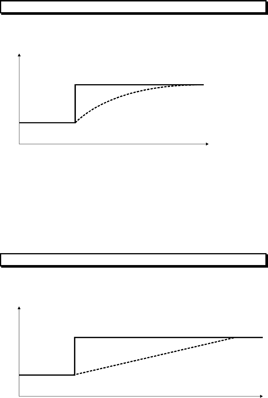
MX4428 MXP Engineering / Technical Manual Document: LT0273
MXP Loop Filter Board
Page 9-2 24 March 2006 Issue 1.5
9.1 EXPONENTIAL FILTER
An “exponential filter” is used to smooth values received from all detector types and remove
“noise”.
Value
Time
IN
OUT
This is a kind of moving average of recent samples, with the most recent samples given the
most weighting. The output of the filter will exponentially approach the input (like an
electronic RC filter).
OUTn = OUTn-1 + (IN - OUTn-1) / FD.
FD is the filter divisor. The bigger FD, the slower the filter.
This filter usually requires calculation using units much smaller than the units being filtered.
For instance it could use floating point arithmetic or integer arithmetic using units of 1/256 of
the “detector units”. Conversion from the calculation units back to detector units should use
rounding rather than truncation.
9.2 STEP LIMITING FILTER
“Step Limiting” is used after the exponential filter on all detector types, to reduce sensitivity
to large short term changes in input values which may represent false alarms.
Value
Time
IN
OUT
Document: LT0273 MX4428 MXP Engineering / Technical Manual
Device Processing
Issue 1.5 24 March 2006 Page 9-3
The output of the filter approaches the input with a maximum slope, or maximum step on
each sample.
ADJ = IN - OUTn-1
IF ADJ > SL THEN ADJ = SL
IF ADJ < -SL THEN ADJ = -SL
OUTn = OUTn-1 + ADJ
SL is the step limit for each sample period. The smaller SL the slower the filter.

MX4428 MXP Engineering / Technical Manual Document: LT0273
MXP Loop Filter Board
Page 9-4 24 March 2006 Issue 1.5
9.3 HEAT PROCESSING
9.3.1 CONVERSION OF DETECTOR READING TO °C
The temperature readings from the detector (814H or the temperature element of an 814PH
or 814CH) are returned from input AI1 of the MX ASIC. These are converted to °C according
to the following table. This gives the closest temperature for each reading.
Rdg °C Rdg °C Rdg °C Rdg °C Rdg °C Rdg °C Rdg °C
0 Fault 40 7 80 26 120 42 160 59 200 80 240 120
1 Fault 41 7 81 27 121 42 161 59 201 81 241 120
2 Fault 42 8 82 27 122 43 162 60 202 82 242 120
3 Fault 43 8 83 28 123 43 163 60 203 83 243 120
4 Fault 44 9 84 28 124 44 164 60 204 84 244 120
5 0 45 9 85 28 125 44 165 61 205 85 245 120
6 0 46 10 86 29 126 44 166 61 206 85 246 120
7 0 47 10 87 29 127 45 167 62 207 86 247 120
8 0 48 11 88 30 128 45 168 62 208 87 248 120
9 0 49 12 89 30 129 45 169 63 209 88 249 120
10 0 50 12 90 30 130 46 170 63 210 89 250 120
11 0 51 13 91 31 131 46 171 64 211 90 251 Fault
12 0 52 13 92 31 132 47 172 64 212 90 252 Fault
13 0 53 14 93 32 133 47 173 65 213 91 253 Fault
14 0 54 14 94 32 134 48 174 65 214 92 254 Fault
15 0 55 15 95 32 135 48 175 66 215 93 255 Fault
16 0 56 15 96 33 136 48 176 67 216 94
17 0 57 16 97 33 137 49 177 67 217 95
18 0 58 16 98 34 138 49 178 68 218 95
19 0 59 17 99 34 139 50 179 68 219 97
20 0 60 17 100 34 140 50 180 69 220 98
21 0 61 18 101 35 141 50 181 69 221 99
22 0 62 18 102 35 142 51 182 70 222 100
23 0 63 19 103 35 143 51 183 70 223 102
24 0 64 19 104 36 144 52 184 71 224 103
25 0 65 20 105 36 145 52 185 72 225 104
26 0 66 20 106 37 146 53 186 72 226 105
27 0 67 20 107 37 147 53 187 73 227 107
28 0 68 21 108 37 148 53 188 73 228 108
29 0 69 21 109 38 149 54 189 74 229 109
30 0 70 22 110 38 150 54 190 74 230 110
31 0 71 22 111 39 151 55 191 75 231 112
32 1 72 23 112 39 152 55 192 75 232 114
33 2 73 23 113 39 153 55 193 76 233 115
34 3 74 24 114 40 154 56 194 77 234 117
35 3 75 24 115 40 155 56 195 77 235 119
36 4 76 25 116 40 156 57 196 78 236 120
37 5 77 25 117 41 157 57 197 79 237 120
38 5 78 25 118 41 158 58 198 79 238 120
39 6 79 26 119 42 159 58 199 80 239 120
The temperature is then processed according to Figure 9.1 to generate the various alarm
and pre-alarm conditions. The RORCV value is also used for enhancement of the smoke or
CO values when this is enabled.
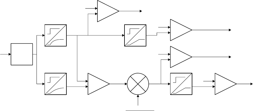
Document: LT0273 MX4428 MXP Engineering / Technical Manual
Device Processing
Issue 1.5 24 March 2006 Page 9-5
Table
Lookup
Exponential
Filter
Slower
Exponential
Filter Subtractor
Raw
Reading
Raw
°
C
Slope
Limiter
Slope
Limiter
Alarm
Threshold
ROR
PreAlarm
Threshold
ROR
Alarm
Threshold
PreAlar
m
Threshold
+
+
+
+
-
-
-
-
Fixed Temp Alarm
Fixed Temp PreAlarm
Comparator
Comparator
Comparator
Comparator
Multiplier
+
-
ROR PreAlarm
ROR
Alarm
CV SLV
RORCV RORSLV
FD1
FD2
PollsPerMinute
FD2-FD1
(°
C/min)
SL1
SL2
Figure 9.1 Heat Processing Diagram
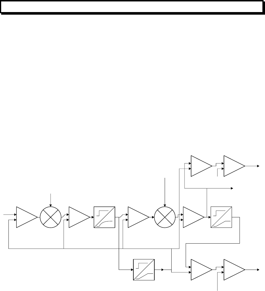
MX4428 MXP Engineering / Technical Manual Document: LT0273
MXP Loop Filter Board
Page 9-6 24 March 2006 Issue 1.5
9.4 PHOTO PROCESSING
9.4.1 SMARTSENSE PROCESSING
The smoke reading of the detector is returned as input AI0 from the device ASIC. Figure 9.2
shows a general view of the processing of the values received from the photoelectric sensor.
It is of interest that the value is multiplied by a factor (between 1 and 4) depending on the
factory calibration of the sensor, and again multiplied by a factor depending on the
temperature rate of rise (when “enhanced” operation is selected). In both cases the “tracked
value” is subtracted, the multiplication applied, and the “tracked value” added back in. This is
so that all scaling occurs relative to the clean air value.
When the MXP or detector powers up the clean air value or “tracked value” is initially set to
the average of the reading from the detector after about 30 seconds and the value stored in
the detector EEPROM, and then may continue to track up or down by 1 each poll for the
next 3 minutes.
When the “tracked value” is reset manually by command from the MX4428, it is set to a
value which will make CV equal to TV. Unless the calibration factor is exactly 1.0, the new
TV is not simply the same as the previous CV.
Subtractor
+
-
Calibration
Adder
Exponential
Filter Subtractor
Enhancement Factor
derived from Heat RORCV
(1 if no enhancement)
Adder
Multiplier
Slope
Limiter
Very Slow Slope
Limiter
(1 step per Photo Tracking Interval)
TV = Tracked Value = Assumed Clean Air Value
Raw
Value
-
+
+
++
+
-
--
-
Alarm Threshold
Alarm
Subtractor
S
ubtractor
Comparator
C
omparator
CV
PreAlarm Threshold
PreAlarm
CVEnh
(CV to FIP)
SLV
Smoke Filter
Divisor Smoke Step
Limit
Figure 9.2 Photo Processing Diagram - SmartSense
9.4.2 SMARTSENSE ENHANCEMENT
Figure 9.3 shows the amount by which smoke readings are increased depending on the
temperature rate of rise.
The default enhancement multiplier parameter is 12. The graph (Figure 9.3) shows the effect
of this factor and also the effect of an alternative parameter of 6.
If enhancement is disabled, (or less efficiently if the enhancement multiplier parameter is set
to 0) the multiplier is exactly 1.
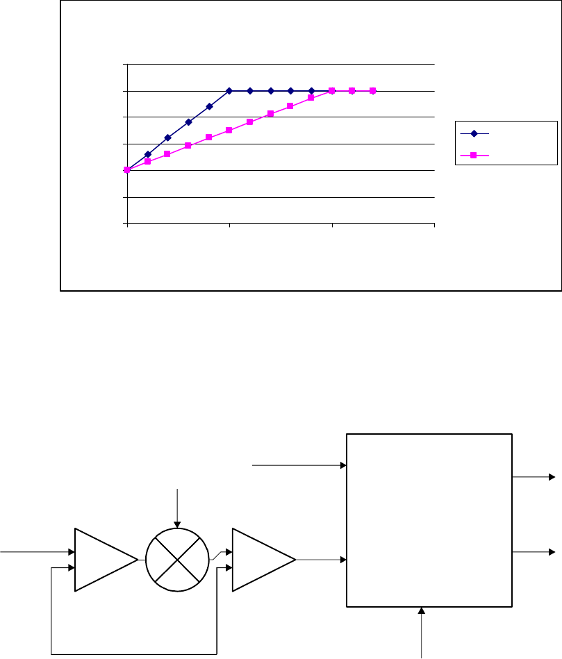
Document: LT0273 MX4428 MXP Engineering / Technical Manual
Device Processing
Issue 1.5 24 March 2006 Page 9-7
Enhancement Multiplier
0
0.5
1
1.5
2
2.5
3
0 5 10 15
Temperature Rate of Rise (°C/min)
Multiplier
Param=12
Param=6
Figure 9.3 Enhancement of smoke reading for temperature rate of rise
9.4.3 FASTLOGIC PROCESSING
When “FastLogic” is selected, most processing is done within the proprietary “FastLogic”
module. The internals of that module are beyond the scope of this manual.
Subtractor
+
-
Calibration
Adder
TV = Tracked Value = Assumed Clean Air Value
(Average of 1st reading and factory stored pedestal)
Raw Smoke
Value Calibrated
Value
Fuzzy Logic Module
Raw heat value
(direct from detector)
Mode
PreAlarm
Alarm
Figure 9.4 Photo Processing Diagram - FastLogic
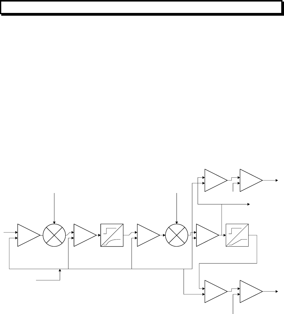
MX4428 MXP Engineering / Technical Manual Document: LT0273
MXP Loop Filter Board
Page 9-8 24 March 2006 Issue 1.5
9.5 CO PROCESSING
9.5.1 CALIBRATION AND TEMPERATURE COMPENSATION
The CO reading of the detector is returned as input AI0 of the device ASIC. The CO
readings are adjusted depending on a calibration factor set at the factory and stored in
EEPROM.
9.5.2 “ENHANCEMENT”
Figure 9.3 shows the amount by which CO readings are increased depending on the
temperature rate of rise. (This is the same for the CO detector as the Photo detector.)
The default enhancement multiplier parameter is 12. The graph (Figure 9.3) shows the effect
of this factor and also the effect of an alternative parameter of 6.
If enhancement is disabled, (or less efficiently if the enhancement multiplier parameter is set
to 0) the multiplier is exactly 1.
9.5.3 CO PROCESSING
Subtractor
+
-
Calibration
Adder Exponential
Filter Subtractor
Enhancement Factor
derived from Heat RORCV
(1 if no enhancement)
Adder
Multiplier
Slope
Limiter
TV = Tracked Value = Zero CO Value
Raw
Value
-
+
+
++
+
-
--
-
Al
a
rm Thr
es
h
o
l
d
Alarm
Subtractor
S
ubtractor
Comparator
C
omparator
PreAlarm Threshold
PreAlarm
CVEnh
(CV to FIP)
SLV
Constant stored
in detector eeprom
CO Filter
Divisor
CO Step Limit
Figure 9.5 CO Processing Diagram
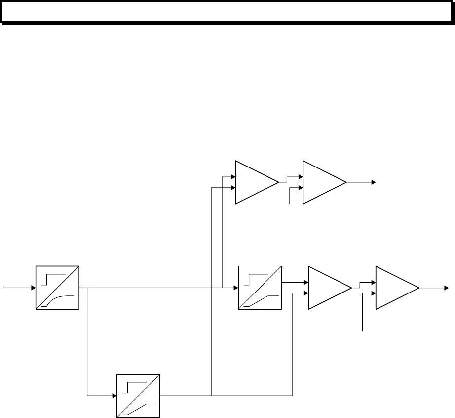
Document: LT0273 MX4428 MXP Engineering / Technical Manual
Device Processing
Issue 1.5 24 March 2006 Page 9-9
9.6 IONISATION PROCESSING
The smoke reading of the detector is returned in two parts as inputs AI0 and AI1 of the
device ASIC. In the MXP the average value of AI0 and AI1 is used for all calculations, so
that all returned values to the MX4428 lie within the range of 0 – 255. (Note that TEPG
literature refers to the sum of the two inputs.)
The processing is shown in Figure 9.6. The tracked value is initialised by setting it to a high
value (100) when the MXP or detector powers up, and allowing the tracked value to
increment / decrement by 1 for each of the first 4 minutes.
Exponential
Filter Slope
Limiter
Very Slow Slope
Limiter
(
1 step per Trackin
g
Interval
)
TV = Tracked Value
= Assumed Clean Air Value
Raw
Value +
++
+
-
--
-
Alarm Threshold
Alarm
Subtractor
Subtractor
Comparator
Comparator
CV
PreAlarm Threshold
PreAlarm
SLV
Filter Divisor Step Limit
Figure 9.6 Ionisation Detector Processing
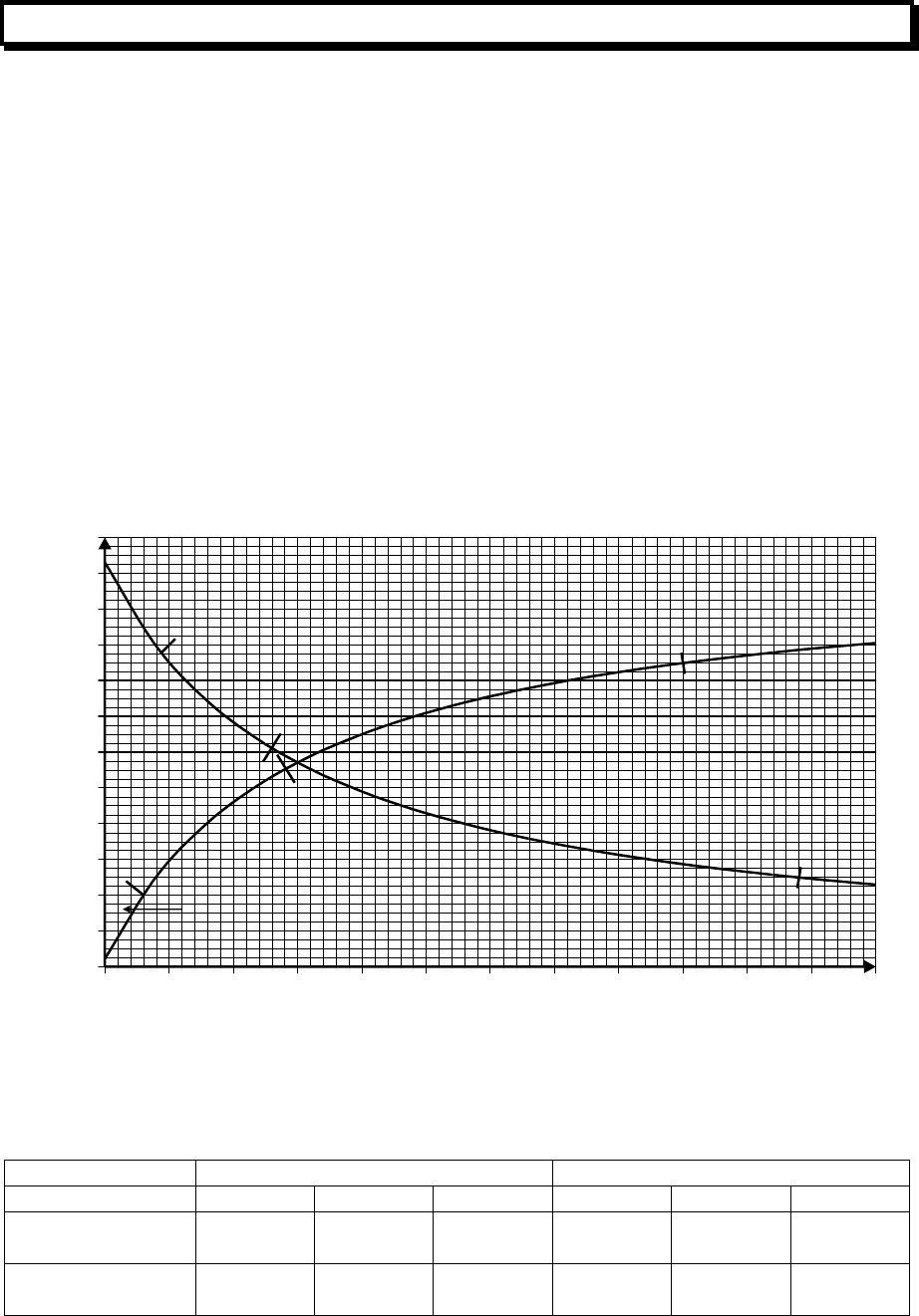
MX4428 MXP Engineering / Technical Manual Document: LT0273
MXP Loop Filter Board
Page 9-10 24 March 2006 Issue 1.5
9.7 MIM800 / CIM800 / MIM801 PROCESSING
The MIM800 and CIM800 return a value which depends on the external resistance across
the contact terminals and which can be modelled by the equation –
VALUE = 226 * (150 + 3) / (150 + Rext + 3)
The MIM801 returns a value which depends on the external resistance across the contact
terminals and which can be modelled by the equation –
VALUE = 226 * (Rext + 3) / (150 + Rext + 3)
(unless Rext is open circuit, then value = 255)
(Note 150 represents an internal 150Ω resistor, 3 represents a 3Ω FET on resistance, and
226 represents (3.3V - DIODEV) / 3.3V * 255
Graphs of these values are show in Figure 9.7. Also shown are the default thresholds, and
the interpretations of the input ranges between the thresholds.
0
20
40
60
80
100
120
140
160
180
200
220
240
0 50 100 150 200 250 300 350 400 450 500 550 600
R
Reading
MIM801
MIM800
N/O : Optional S/C Fault
N/O : Alarm
N/C:
O/C Fault
N/C : S/C Fault
N/O :
Alarm
N/O :
Optional S/C Fault
Normal
Normal
N/O :
O/C Fault
N/C :
Alarm
N/O :
O/C
Fault
N/C :
Alarm
176
122
110
40 50
170
Figure 9.7 MIM800 / MIM801 Reading versus resistance
The usual parameters are as follows –
MIM800 / CIM800 MIM801
P0 P1 P2 P3 P4 P5
No alarm resistor
(Default) 122 50 0 110 170 0
With alarm
resistor 176 40
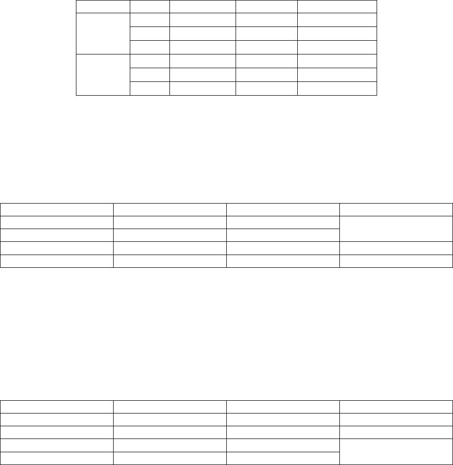
Document: LT0273 MX4428 MXP Engineering / Technical Manual
Device Processing
Issue 1.5 24 March 2006 Page 9-11
These are designed for the following configurations–
Device Mode Contact R EOL R Max Wiring R
N/O Not used 200Ω 50Ω
N/O 100Ω 200Ω 10Ω
MIM800
CIM800
N/C 200Ω 50Ω
N/O Not used 200Ω 50Ω
N/O 100Ω 200Ω 10Ω
MIM801
N/C 200Ω 50Ω
Parameters for alternative contact and EOL resistors could be derived from the graphs in
Figure 9.7.
9.7.1 ALGORITHM - MIM800, CIM800
The unverified input condition is evaluated according to the following table, depending on the
mode (N/O or N/C) and the values of parameters P0, P1, and P2.
P2=0 P2 not = 0 N/O N/C
P2<=reading<=255 Short circuit fault
P0<=reading<=255 P0<=reading<P2 Alarm
Short
P1<=reading<P0 P1<=reading<P0 Normal Normal
0<=Reading < P1 0<=Reading < P1 Open circuit fault Alarm
Changes in these states are verified as described in section 9.22.
For the CIM800, if either input is in fault, the point will be in fault. If either input is in alarm,
the point will be in alarm. It may therefore be in fault and alarm at the same time.
9.7.2 ALGORITHM - MIM801
The unverified input condition is evaluated according to the following table, depending on the
mode (N/O or N/C) and the values of parameters P0, P1, and P2
P5=0 P5 not = 0 N/O N/C
P4<=reading<=255 P4<=reading<=255 Open circuit fault Alarm
P3<=reading<P4 P3<=reading<P4 Normal Normal
0<=Reading < P3 P5<=Reading < P3 Alarm
0<=Reading < P5 Short circuit fault Short circuit fault
Changes in these states are verified as described in section 9.22.
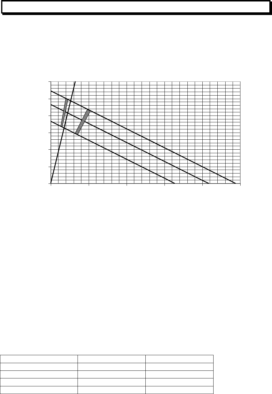
MX4428 MXP Engineering / Technical Manual Document: LT0273
MXP Loop Filter Board
Page 9-12 24 March 2006 Issue 1.5
9.8 DIM PROCESSING
9.8.1 LOAD GRAPH
Figure 9.8 shows the V / I characteristics for the DIM detector terminals, together with the
fault and alarm thresholds when using the default parameters. The shaded areas show the
region of uncertainty.
Three lines are shown for three supply voltages.
0
5
10
15
20
25
30
0 102030405
0
Load Current
(
mA
)
Loa
d
V
o
l
tage
28V
24V
19V
4k7 EOL
ALARM
NORMAL
FAULT
Figure 9.8 DIM LoadLine Characteristics
9.8.2 DIM MODEL
The reading from the DIM module can be modelled using the following method.
Calculate “R” from a point on the load line = Load Voltage / Load Current.
Reading = 137000 / (560 + R)
For example take the point where the 4k7 EOL resistor crosses the 24V line.
R = 20.8 / .0044
= 4700
Reading = 137000 / (560 + 4700)
= 26
Note that for a given “R”, the reading is independent of the supply voltage.
9.8.3 ALGORITHM - DIM800
The unverified input condition is evaluated according to the following table, depending on the
values of parameters P1, P2, and P4. (if P4 is 0, assume it is 225).
Input Condition (Mode 0) Condition (Mode 1)
P4 <= reading <= 255 Alarm Short
P1 <= reading < P4 Alarm Alarm
P2 <= reading < P1 Normal Normal
0 <= reading < P2 Open circuit fault Open circuit fault
Changes in these states are verified as described in section 9.22.

Document: LT0273 MX4428 MXP Engineering / Technical Manual
Device Processing
Issue 1.5 24 March 2006 Page 9-13
9.8.4 SUPPLY MONITORING - DIM800
The DIM800 supply is monitored with input AI3 of the device ASIC. If the supply voltage is
less than 18V, a SUPPLY FAIL fault is generated. (The threshold can be changed with
parameter 3 if needed.) If the supply fails completely, a DIM800 with revision less than 10
will stop responding to polls and a NODE FAIL fault is generated.
9.9 RIM PROCESSING
9.9.1 POSITION MONITORING
Correct Relay state DI0 Condition
0 OK Not activated 1 Relay Stuck
0 Relay Stuck Activated 1 OK
Changes in these states are verified as described in section 9.22. Verified faults
representing a “relay stuck” condition are logged as CONTROL CB FAIL at the MX4428,
with the return to normal event logged as CONTROL CB NML.
9.10 SNM PROCESSING
9.10.1 PROGRAMMING
Supply Monitoring Required DO6
No 1
Yes 0
9.10.2 SUPPLY FAULT DETERMINATION
Input AI1 Condition
AI1 > P3 Supply Fault
AI1 <= P3 Supply OK
Note that Parameter 3 cannot reliably be adjusted to monitor supplies of different voltages.
9.10.3 EOL AND POSITION MONITORING
Correct Relay Position AI0 Condition
P1 < AI0 <= 255 Open circuit fault
P2 <= AI0 <= P1 Normal
0 <= AI0 < P2 Short circuit fault
Not activated
Any No Position Fault
Any No Open Circuit Fault
No Short Circuit Fault
P1 <= AI0 < 255 No Relay Stuck Fault
Activated
0 <= AI0 < P1 Relay Stuck Fault
Changes in these states are verified as described in section 9.22.

MX4428 MXP Engineering / Technical Manual Document: LT0273
MXP Loop Filter Board
Page 9-14 24 March 2006 Issue 1.5
Both short circuit faults and open circuit faults will be logged as SUPERVISION FAULT, and
relay stuck faults will be logged as CONTROL CB FAIL. Only the first fault will be logged.
When all relay faults go away, the event logged at the MX4428 will be NORMAL OFF or
NORMAL ON as the case may be, regardless of the original fault logged.
9.11 LPS PROCESSING
9.11.1 ELD AND POSITION MONITORING
Correct Relay Position AI0, AI1 Condition
AI0 > 200 AND AI1 < 50 Open circuit fault
50 < AI0 <= 110 Short circuit
0 <= AI0 <=50 Relay fault
Not activated
Otherwise Normal
AI0 > 50 Relay Fault
AI0 <= 50 AND AI1 <= 50 Short circuit
AI0 <= 50 AND 50 < AI1 <= 200 Relay Fault
Activated
Otherwise Normal
Changes in these states are verified as described in section 9.22.
Both short circuit faults and open circuit faults will be logged as SUPERVISION FAULT, and
relay stuck faults will be logged as CONTROL CB FAIL. Only the first fault will be logged.
When all relay faults go away, the event logged at the MX4428 will be NORMAL OFF or
NORMAL ON as the case may be, regardless of the original fault logged.
9.12 VLC800 PROCESSING
9.12.1 GENERAL
The VLC800 is processed like an 814PH, with the following parameters.
Tracked Value is fixed at 12.
Alarm Threshold is fixed at 100. (Corresponding to a raw value of 112).
Filter Divisor is fixed at 3.
Step Limit is 255 (so essentially there is no step limit).
PreAlarm is adjustable at the MX4428.
So the only filtering is the exponential filter with a filter divisor of 3. This gives some filtering,
but with a minimal delay.
As the alarm threshold is always 100, the current level (CV-TV) is an indication of the smoke
level in terms of % of the alarm threshold programmed into the VLC800 itself.

Document: LT0273 MX4428 MXP Engineering / Technical Manual
Device Processing
Issue 1.5 24 March 2006 Page 9-15
9.13 FILTER STEP LIMITS
Note that Step Limits are always expressed as “Units per 5 seconds”. This differs from MPR
where heat units are “units per 10 seconds”, but smoke limits are “time to alarm” (the
inverse). The MXP change results in
• Heat and smoke being consistent with each other.
• Using a constant slope, rather than a constant time to alarm, as the threshold is varied,
means that increasing the alarm threshold also means that the minimum time to alarm
will be increased which is generally what would be expected. This gave better results
with the various sensitivities of the photo detector in the SSL test room, i.e. a constant
Step Limit could be used for all sensitivities.
9.14 ZONE ALARM TEST
A zone alarm test performs a test in the detector for all detectors in a zone which are
capable of supporting it viz 814PH, 814CH, and 814I. The Detector LEDs do not operate. No
filtering is applied during remote tests and the fuzzy logic is replaced by a simple comparison
test. Any devices already in alarm, prealarm or fault, or isolated, do not partake in the test.
Failure of a capable detector to produce the expected output generates an immediate fault.
The actual alarm returned to the MX4428 goes through AVF if programmed.
The MXP does not return “Test Pass” until all alarm-capable devices in the circuit go into
alarm.
9.15 ZONE FAULT TEST
No MX detectors are capable of a remote fault test. Therefore with all detectors and devices
a fault is simulated in polling software.
“Test Pass” requires all devices in the circuit to pass.
9.16 AUTOTEST AND SYSTEM TEST
The Flash Checksum is checked. (Note also, a checksum fail on power up will result in the
MXP application software not even starting, but the MXP will await a program load via its
diagnostic port.)
Specific checking of the configuration RAM is not required as it is being continually checked
(with anomalies resulting in a download request from the MX4428).
For an autotest where remote device testing is enabled in the MX4428, and for all system
tests, all detectors which are capable of a remote alarm test are tested. The LEDs do not
operate and no alarms caused only by the remote test are returned to the MX4428. A device
with an external wiring fault or which is isolated, or in alarm or pre-alarm, is not subject the
test and is not reported. A device with a fault, other than external wiring, or which is in scan
fail scan fail, or relay checkback fail, or type mismatch, results in failure of the test (abnormal
at start). No filtering is applied during remote tests.

MX4428 MXP Engineering / Technical Manual Document: LT0273
MXP Loop Filter Board
Page 9-16 24 March 2006 Issue 1.5
9.17 NON LATCHING TEST MODE
In this mode no alarms are latched, and all filtering is bypassed, however detector and
device LEDs follow the alarm status. About 10 seconds after a device goes into alarm it is
automatically “held in reset” for about 10 seconds, and then sampling starts again from the
beginning.
9.18 COMMISSION MODE
Filtering is speeded up or bypassed. AVF is bypassed.
9.19 FAST POINT TEST
A point which supports remote test is put into alarm by its remote test facility. A point which
does not support remote test is put into alarm by simulating a high reading. Filtering is
speeded up or bypassed. AVF is bypassed.
9.20 SLOW POINT TEST
A point which supports remote test is put into alarm by its remote test facility. A point which
does not support remote test is put into alarm by simulating a high reading. Filtering and
AVF operate normally.
9.21 SUMMARY OF ALL TEST MODES
Table 9-1 shows the features of the various alarm tests which may be applied to detectors
and input ancillary devices.
Note that there is no remote test facility on a 8xxH heat detector or on the heat component of
a 8xxPH or 8xxCH detector. On MX4428 there is no way to specify an alarm test on the heat
component of an 8xxPH or 8xxCH detector.

Document: LT0273 MX4428 MXP Engineering / Technical Manual
Device Processing
Issue 1.5 24 March 2006 Page 9-17
AutoReset Commission
Mode Zone
Alarm
Test
System
test.
Auto test
with test
fire
Fast
Point
Test
Slow Point Test Normal
Detector test
applied No
Yes on smoke / CO
(Alarm result simulated on 8xxH
ie Heat only detector and on
ancillary input modules)
Yes on smoke / CO.
Simulated 100°C on 8xxH.
Simulated alarm on
ancillaries.
No
FastLogic Switches to SmartSense As cfgd As cfgd
Filter Divisor 2 on Smoke / CO
As cfgd on heat 1 (bypassed) As cfgd As cfgd
Enhancement None None None As cfgd
Step Limit Bypassed Bypassed As cfgd As cfgd
AVF Bypassed
As cfgd
on DIM.
Bypassed
on analog
detectors
N/A Bypassed As cfgd As cfgd
Detector / Anc
LED operates Yes No No Yes Yes Yes
Circuit / zone
goes into
alarm
Yes - but
zone
isolated at
FIP
Yes
When
ALL
points in
alarm
No Yes Yes When alarm
condition
reached
Point alarm
generates
event Yes Yes No No Yes Yes Yes
History high,
low updated No Yes No No No No Yes
Tracking
updated No Yes No No No No Yes
FIP CV
Updated Yes Yes No No No Yes Yes
Reset
terminates test No effect at MXP Yes Yes N/A
Table 9-1 Test Modes Summary
9.22 ANCILLARY FILTERING
If a poll returns the alarm state, then up to 5 immediate re-polls are made. If all these are still
in the alarm state then an alarm is generated. If one of the succeeding polls is not in the
alarm state, then immediate re-polling stops, but an up-down counter will be retained for the
next poll. This counter counts up when an alarm condition is measured, and down when a
non-alarm condition is measured. So if there are 5 polls in the alarm state then 1 non alarm
the counter will be left at 4. On the next scheduled poll the counter starts from the value it
had previously, so only 2 successive polls returning the alarm condition will be required to
reach the alarm condition.
The up-down counter always counts up and down (between 0 and 6) depending on whether
an alarm condition or not is read from the detector. When the counter reaches 6 a filtered
alarm state is generated. When the counter reaches 0 a filtered non-alarm condition is
determined. An immediate re-poll is done if the last poll is in the opposite state to the filtered
state.
Ancillary faults are filtered in the same way, except that only 4 polls are needed rather than
6, and there is no immediate re-polling, 4 polls 5 seconds apart are required.

MX4428 MXP Engineering / Technical Manual Document: LT0273
MXP Loop Filter Board
Page 9-18 24 March 2006 Issue 1.5
9.23 RESET
9.23.1 RESET OF ADDRESSABLE DETECTOR
For about 20 seconds after reset is applied to an addressable detector, the exponential filter
and slope limiting filter are disabled if their input values are less than their output values. In
other words their outputs will follow their inputs downwards with no filtering. However
increases in input values will be filtered as usual.
If the LED is latched on due to a previous alarm it will be turned off.
The state of any AVF applied to the detector is reset to the “no-alarm” quiescent state.
RESET has no effect on 814PH detectors operating in “FastLogic” mode.
9.23.2 RESET OF DIM MODULE
Power is removed from the attached conventional detectors for about 5 seconds. Then
power is re-applied, and sampling resumes 5 seconds later.
If the DIM module LED is latched on due to a previous alarm it will be turned off.
The state of any AVF applied to the detector is reset to the “no-alarm” quiescent state.
9.23.3 RESET OF ANCILLARY INPUT DEVICE
If the LED is latched on due to a previous alarm it will be turned off.
The state of any AVF applied to the detector is reset to the “no-alarm” quiescent state.
9.23.4 RESET OF ANCILLARY OUTPUT DEVICE
No action.

Document: LT0273 MX4428 MXP Engineering / Technical Manual
Device Processing
Issue 1.5 24 March 2006 Page 9-19
9.24 DEVICE INITIALISATION AND POLLING
The following actions are taken for each device when it powers up or when the MXP powers
up. One action is performed on (or instead of) each 5 second poll.
• If fault bit was received, use HEALTH command to verify that fault was caused by
powerup.
• Use READEE command to check type.
• Send SETALL command to select which values are returned, to set the interrupt
thresholds (if any), set the Digital Outputs required for correct operation and set the
status register for LED blink if required.
• Use READEE command to get factory calibration value for Photo and CO devices.
• Use READEE command to get factory “clean air” value for Photo and CO devices.
• Use READEE command to get the stored LED blink bit. This may require the SETALL
command to be sent again.
Once this is complete FASTAV commands will be used to read the analog inputs (FASTDI
command for RIM) on each poll, except for the occasional use of the SETOUT command to
Reset / unreset the DIM detectors and as a background refresh of digital outputs.
SETOUT commands to set changed digital outputs will be interspersed between polls, with
no request to return data.
GLOBADR commands are used to find all devices during a “Learn” initiated by the MX4428
and “Diagnostic Pollscan” initiated by the MX4428 or MXP diagnostic terminal.
(Refer to the “NOSEx SPECIFICATION” document for more details of the above
commands.)

MX4428 MXP Engineering / Technical Manual Document: LT0273
MXP Loop Filter Board
Page 9-20 24 March 2006 Issue 1.5
9.25 SOFTWARE VERSIONS
The following software versions have been released for general use.
Version Features
1.03 First full release
1.04
(Limited
Release)
Fixed failure of photo self test when using fuzzy logic with some detectors.
Fixed standalone mode did not work if no valid database.
1.05
(Limited
Release)
Added "typewrite" command to easily reprogram CO self test pulse length.
Fixed failure of CO self test with new detectors, and subsequent other faults
due to the detector powering down.
1.06 Fixed failure of photo self test when using fuzzy logic with some detectors.
Fixed standalone mode did not work if no valid database.
Added "typewrite" command to easily reprogram CO self test pulse length.
Fixed failure of CO self test with new detectors, and subsequent other faults
due to the detector powering down.
Added automatic detection of CO detectors with insufficient self test pulse
length (as stored in detector eeprom), and correction thereof.
Fixed threshold used for remote test of photo detector using fuzzy logic with
individual sensitivity.
Fixed reporting of scan-fail (problem introduced in 1.05).
Changed version returned to MX4428 from c0 to c6.
1.07 Implemented fast and slow point test, commission mode.
Fixed no scan fail fault on CH detector (introduced in V1.06)
Added support for LPS800. (Programmed as SNM800)
Changed version returned to MX4428 to c7.
1.09 Added support for Vesda VLC800.
Amended 814I remote test decision to prevent some detectors from
incorrectly failing a remote test.
Changed version returned to MX4428 to c9.
1.10 Fixed CO detector processing. Versions 1.07 to 1.09 inclusive did not apply
the "calibration factor" stored in the detector eeprom, meaning that most
detectors were less sensitive than they should have been (possibly outside
the SSL limits of +/- 50%).
VLC800 self test - moved decision point to the third poll after the "stimulus".
(The data at the previous decision point was not necessarily valid.)
Reprogrammed the eeprom containing the pulse length to the length required
for the self test
MX4428 Analog diagnostics AO command did not always cancel AS and AQ
commands. (PR was workaround.) AO now fixed.
Changed version returned to MX4428 to $ca.
1.11 DIM800 now has an option for short circuit fault
Fixed the problem that where there was only one DIM800 on the loop, and it
was the only device on the loop, it did not get processed.
Fixed the 814PHFL Fastlogic modes, in particular smoke only actually
selected heat only.
Changed version returned to MX4428 to $cb.
1.12 Fixed continual transmission of global maintenance alert on then off when a
“dirty” point was isolated. Changed version returned to MX4428 to $cc.

Document: LT0273 MX4428 MXP Engineering / Technical Manual
MXP Loop Filter Board
Issue 1.5 24 March 2006 Page 10-1
CHAPTER 10
MXP LOOP FILTER BOARD
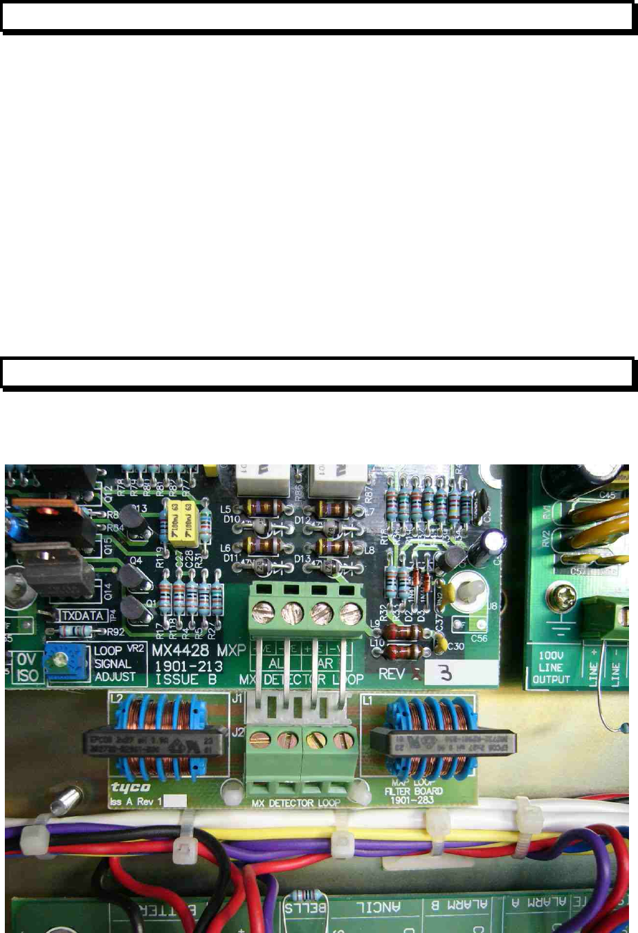
MX4428 MXP Engineering / Technical Manual Document: LT0273
MXP Loop Filter Board
Page 10-2 24 March 2006 Issue 1.5
10.1 USE OF MXP LOOP FILTER BOARD
Some field problems have occurred with the MXP detector loop picking up interference from
adjacent or nearby wiring, resulting in faults and possibly prealarms. The “MXP Loop Filter
board” (part number PA1038) is now available and it can easily be fitted to an MXP in order
to remove the interference and restore normal operation.
One or more of the following symptoms may be evident –
1. Intermittent “scan fail” faults.
2. Intermittent unexpected Prealarms.
3. The MXP diagnostic port “Total reply fail count” is much higher than expected
(normally you should get less than 1 per hour).
4. The above problems occur in time with some external event e.g. lift motors running,
radio transmitters operating etc.
Note that symptoms 1 – 3 above can also be caused by other factors e.g. the loop has too
many devices connected or is too long. The MXP Loop Filter board will not help if this is the
case.
10.2 FITTING
Remove the loop wiring from the MXP. Fit the filter board in the loop wiring terminals of the
MXP. Then fit the loop wiring to the filter board. Refer to Figure 10.1.
Figure 10.1 MXP Loop Filter Board Fitted to an MXP

Document: LT0273 MX4428 MXP Engineering / Technical Manual
MXP Loop Filter Board
Issue 1.5 24 March 2006 Page 10-3
Note – if you are fitting the board to an MXP in a responder box, you may need to tip the
underside of the plastic standoffs inwards to get the board to fit into the MXP board
connector easily – it will help if you rotate each standoff so that its plastic latch is pointing
away from the edge of the board. Once the board is inserted you can straighten the
standoffs before tightening the screws on the MXP loop wiring terminals.
Be sure to check that the system is operating normally, and that the problem you started with
is solved.
10.3 DIAGNOSTICS
Connect a terminal or laptop running a terminal emulator program to the MXP diagnostics
port using LM0041. Select baud 19200, no parity, 8 databits, 1 stop bit.
Enter the command RS. This will reset the error counters. Wait a few minutes. Enter TC. The
“Total reply fail count” count should be zero. Keep checking it periodically. It should not
increase by more than about 1 per hour. If there is a problem the count may increase every
few seconds. To try to correlate the errors/retries with other events you can keep typing TC
(or Control-R to repeat the last command) and see when the errors are occurring.
Alternatively to try to correlate the errors/retries with other external events you can enter the
command NC (Nosex comms log toggle) so that the Nosex comms log is enabled. Then you
will see activity on the screen in real time every time a device does not reply. (Note - one
device that should not be present is polled every 5 seconds, it should not reply and this lack
of reply is displayed on the screen). Be sure to type NC again so that the Nosex Comms log
is disabled before disconnecting the terminal.
MX4428 MXP Engineering / Technical Manual Document: LT0273
MXP Loop Filter Board
Page 10-4 24 March 2006 Issue 1.5
THIS PAGE INTENTIONALLY LEFT BLANK
