UAB Teltonika RUT240A LTE Router User Manual
UAB Teltonika LTE Router
UserManual.wiki
>
UAB Teltonika
>
RUT240A User Manual
User Manual
Navigation menu
Upload a User Manual
Namespaces
Wiki Guide
HTML
PDF
Info
Views
User Manual
Discussion / Help
Navigation
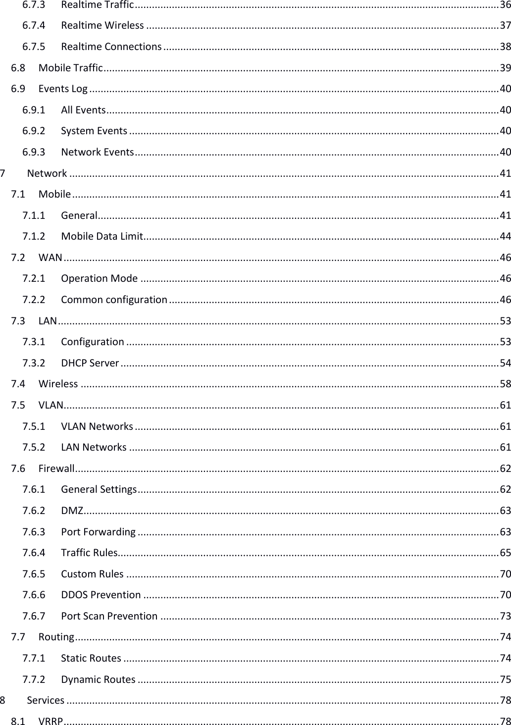
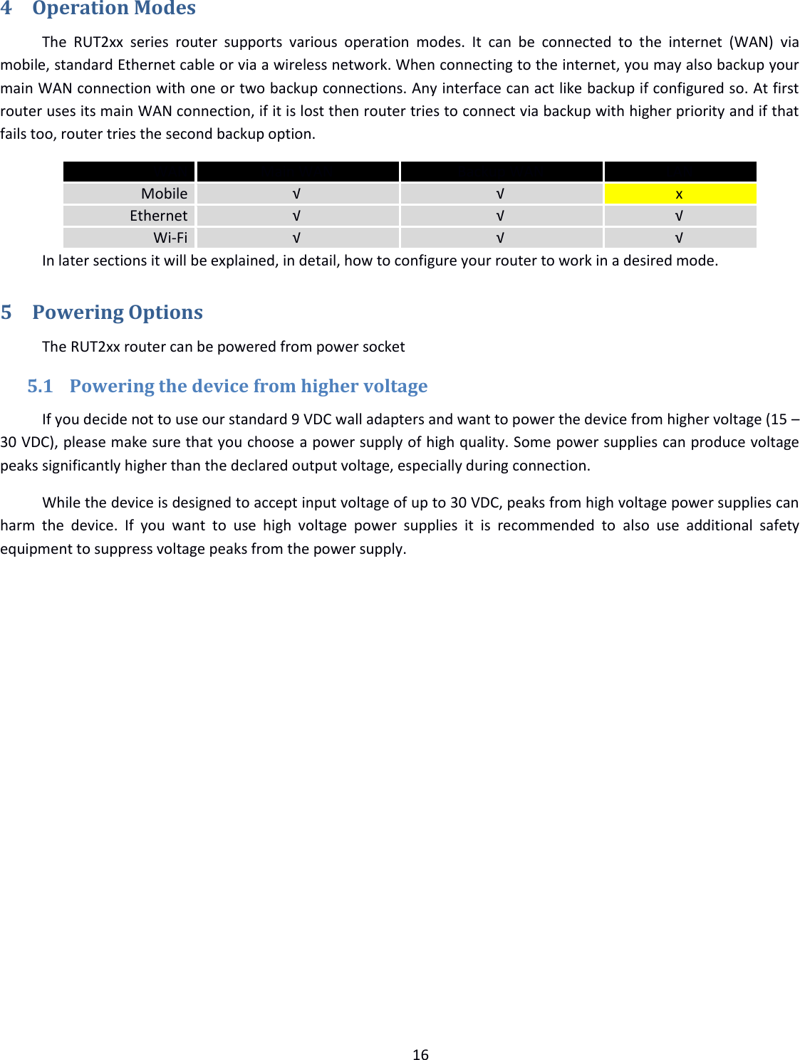
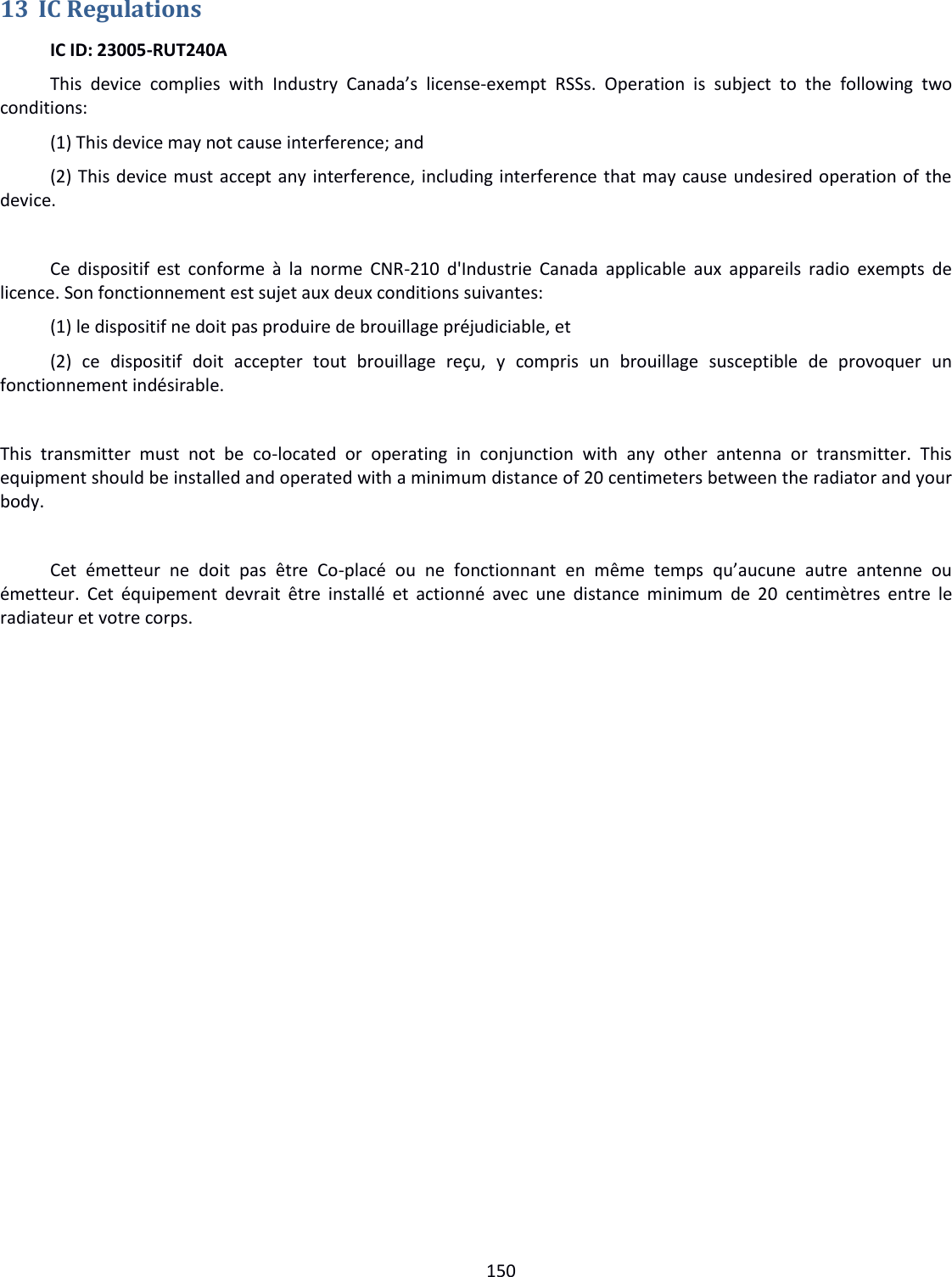
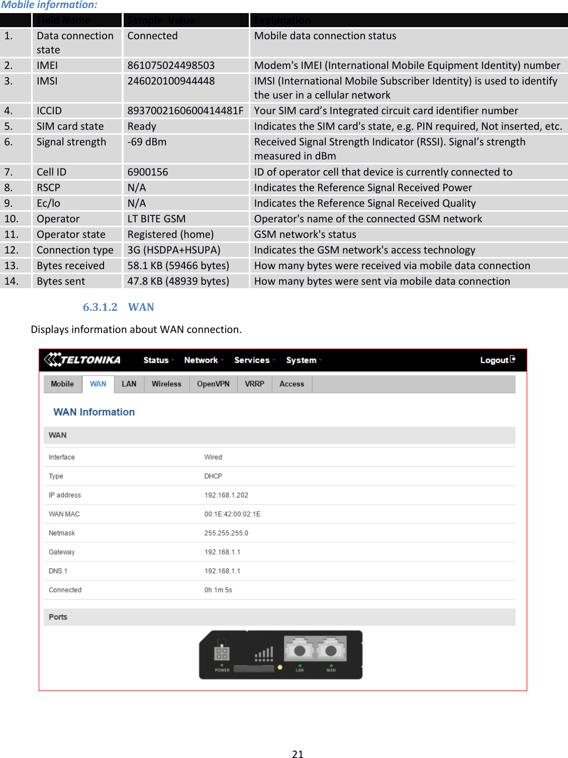
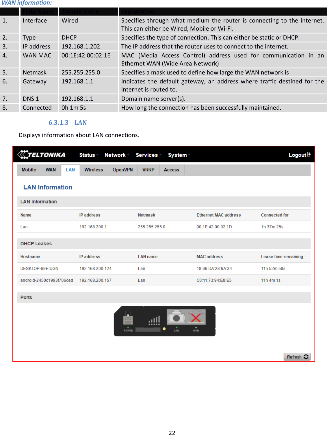
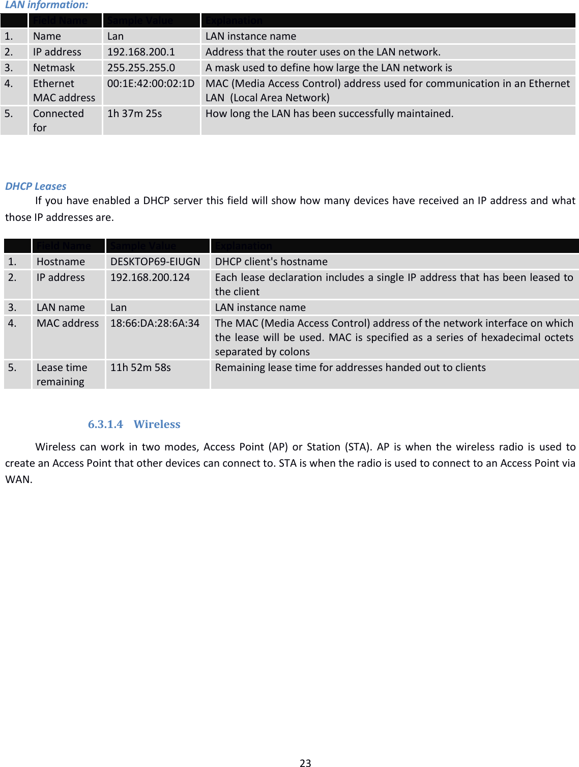
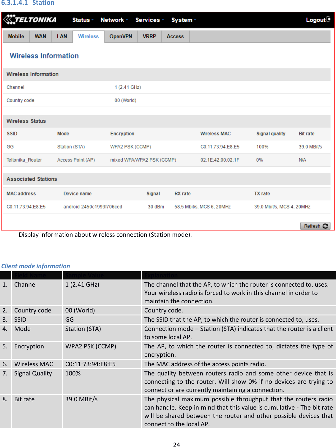
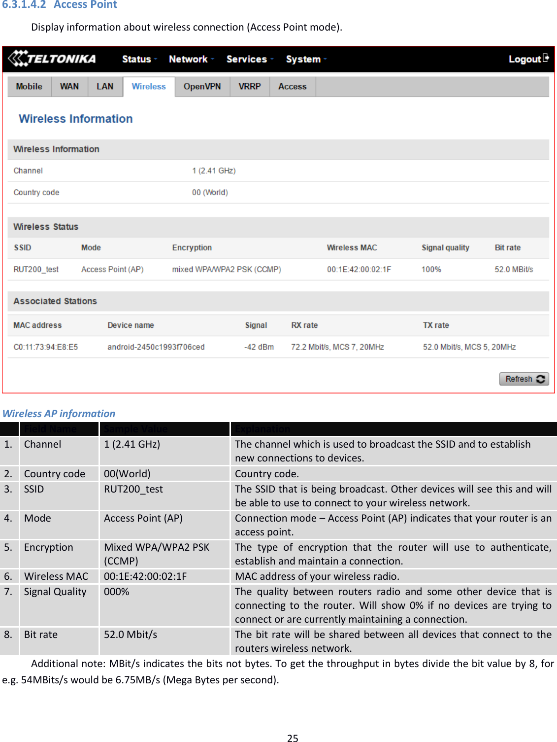
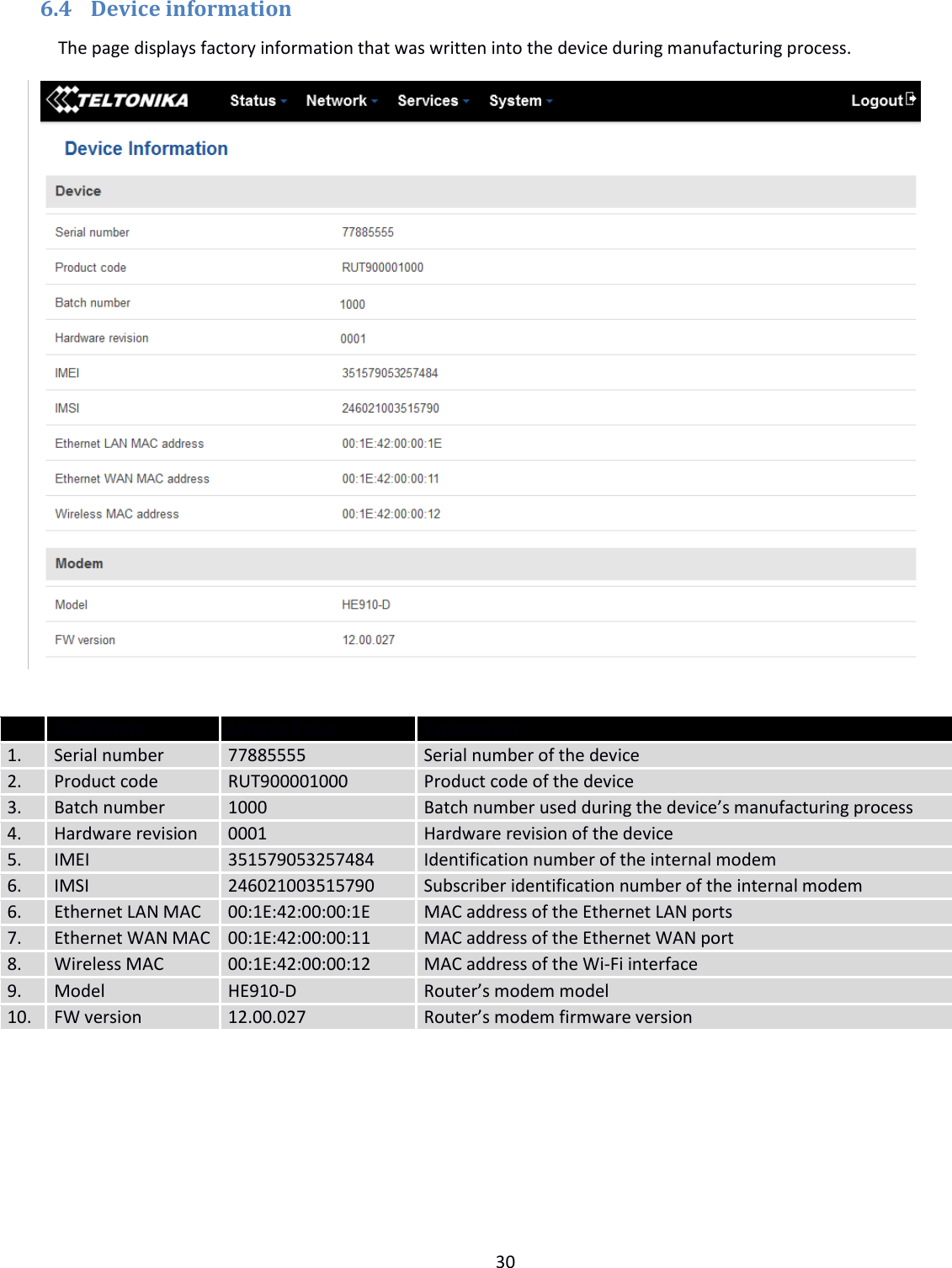
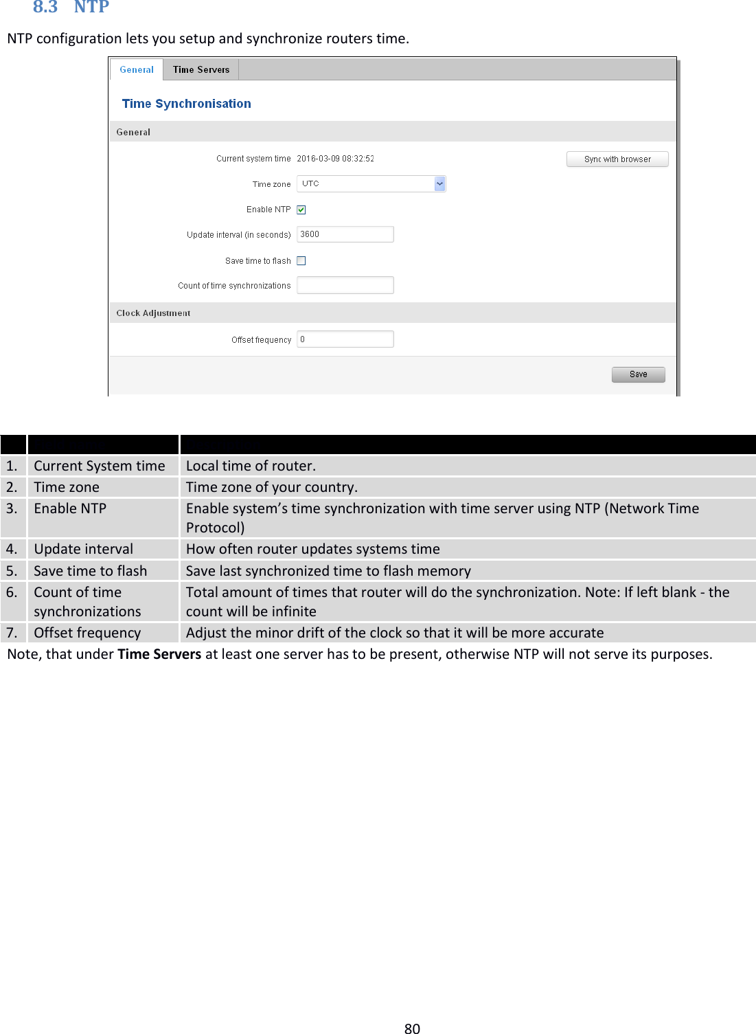
![19 System explanation: Field Name Sample value Explanation 1. Router Name RUT240 Name of the router (hostname of the router’s system). Can be changed in System -> Administration. 2. Host name Teltonika-RUT240.com Indicates how the router will be seen by other devices on the network. Can be changed in System -> Administration. 3. Router Model Teltonika RUT240 3G Router’s model. 4. Firmware Version RUT2XX_T_00.00.20 Shows the version of the firmware that is currently loaded in the router. Newer versions might become available as new features are added. Use this field to decide whether you need a firmware upgrade or not. 5. Kernel Version 3.18.44 The version of the Linux kernel that is currently running on the router. 6. Local Time 2017-04-12, 14:41:18 Shows the current system time. Might differ from your computer, because the router synchronizes it's time with an NTP server. Format [year-month-day, hours: minutes: seconds]. 7. Uptime 0d 0h 59m 42s (since 2017-04-12, 13:41:36) Indicates how long it has been since the router booted up. Reboots will reset this timer to 0. Format [days hours minutes seconds (since year-month-day, hours: minutes: seconds)]. 8. Load Average 1 min: 5%; 5 mins: 72%; 15 mins: 76% Indicates how busy the router is. Let's examine some sample output: "1 min: 5%, 5 mins: 72%, 15 mins: 76%". The first number means past minute and the second number 5 means that in the past minute there have been, on average, 5% processes running or waiting for a resource. 9. Temperature 40° C Device’s temperature Memory explanation: Field Name Sample Value Explanation 1. Free 14924 kB / 61020 kB (24%) The amount of memory that is completely free. Should this rapidly decrease or get close to 0, it would indicate that the router is running out of memory, which could cause crashes and unexpected reboots. 2. Cached 16992 kB / 61020 kB (27%) The size of the area of memory that is dedicated to storing frequently accessed data. 3. Buffered 6740 kB / 61020 kB (11%) The size of the area in which data is temporarily stored before moving it to another location.](https://usermanual.wiki/UAB-Teltonika/RUT240A/User-Guide-3902235-Page-19.png)
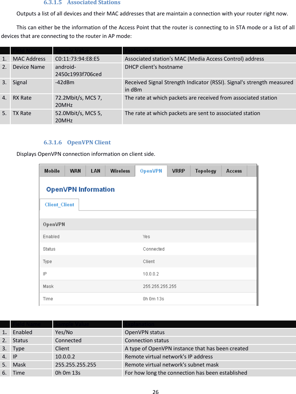
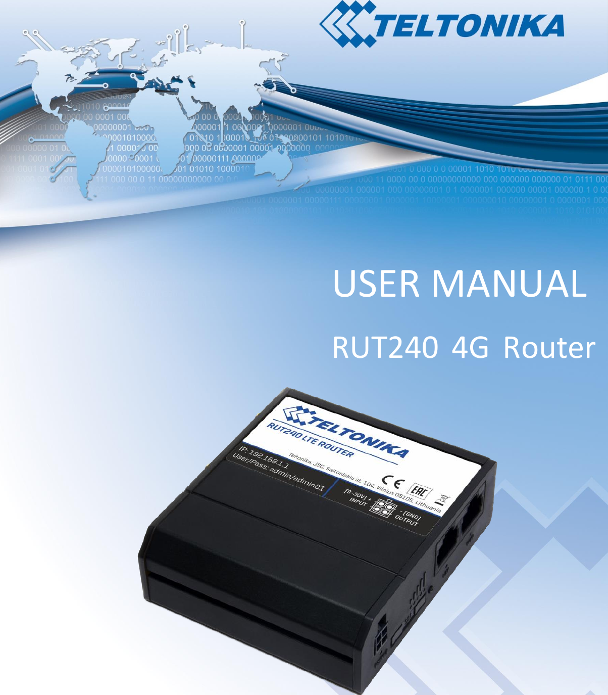
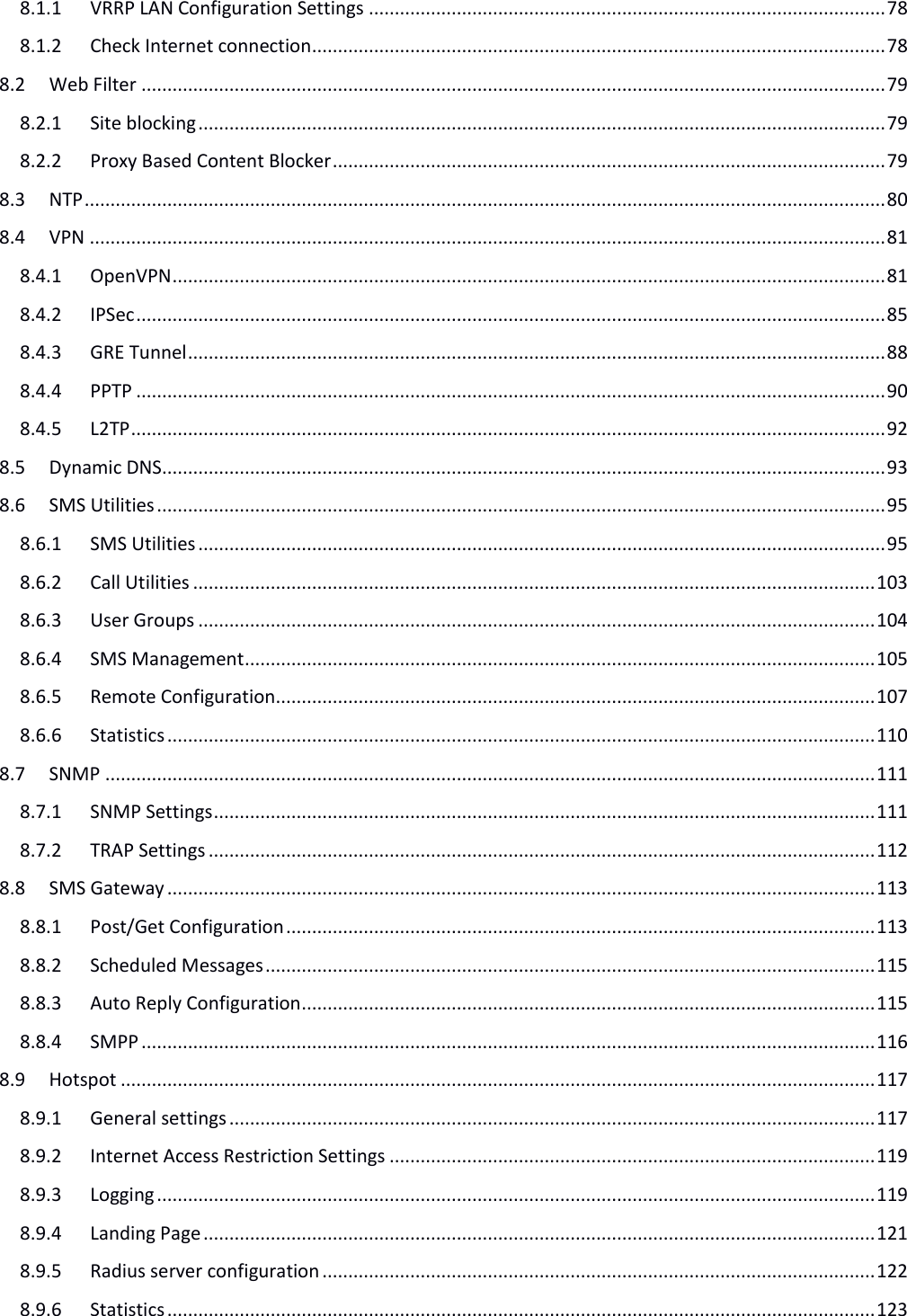
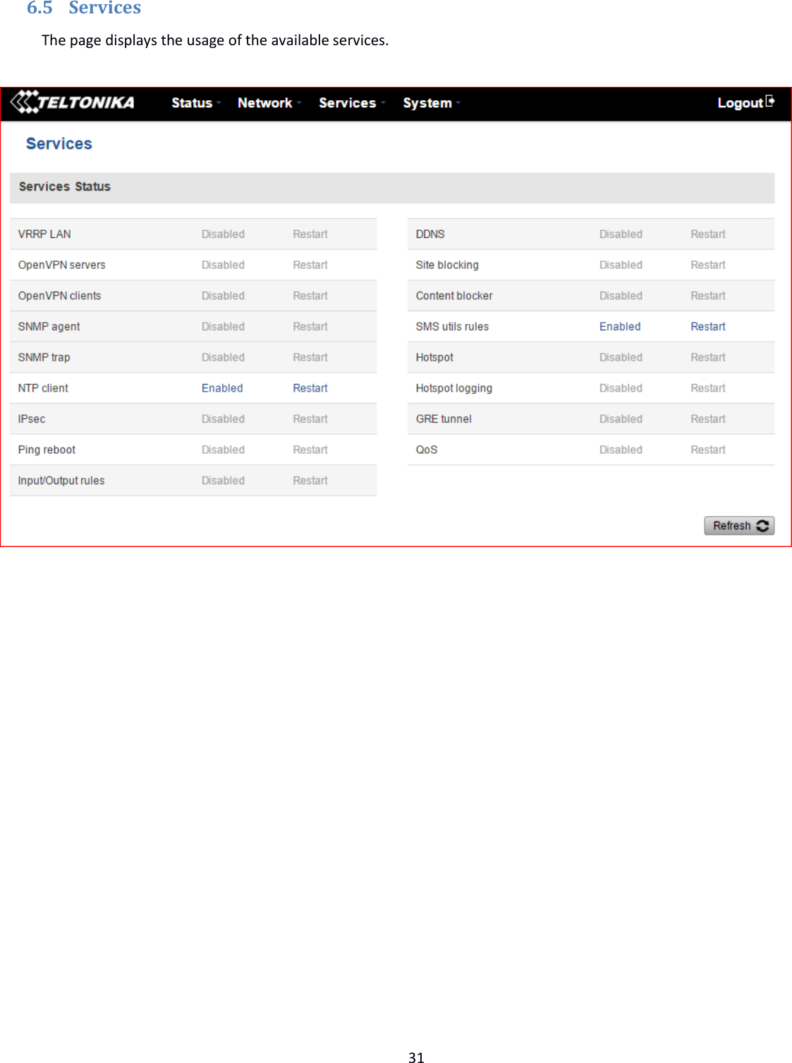
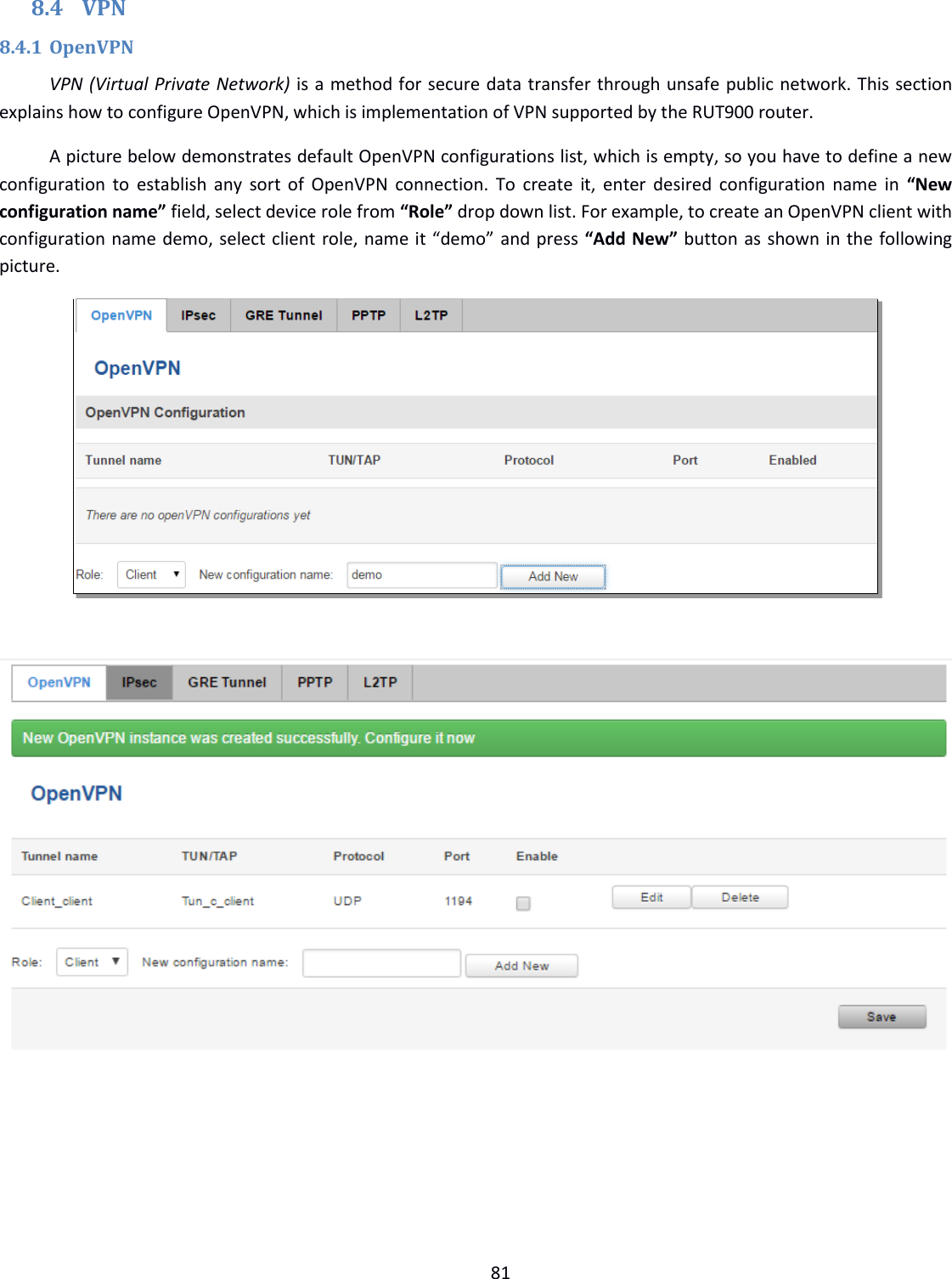
![28 6.3.1.9 VRRP VRRP (Virtual Router Redundancy Protocol) for LAN Field Name Sample Value Explanation 1. Status Enabled VRRP status 2. Virtual IP 192.168.1.253 Virtual IP address(-es) for LAN’s VRRP (Virtual Router Redundancy Protocol) cluster 3. Priority 100 Router with the highest priority value on the same VRRP cluster will act as a master, range [1 - 255] 4. Router** Master Connection mode – Master **-Exclusive to other Modes with Slave. 6.3.1.10 Access Display information about local and remote active connections status.](https://usermanual.wiki/UAB-Teltonika/RUT240A/User-Guide-3902235-Page-28.png)
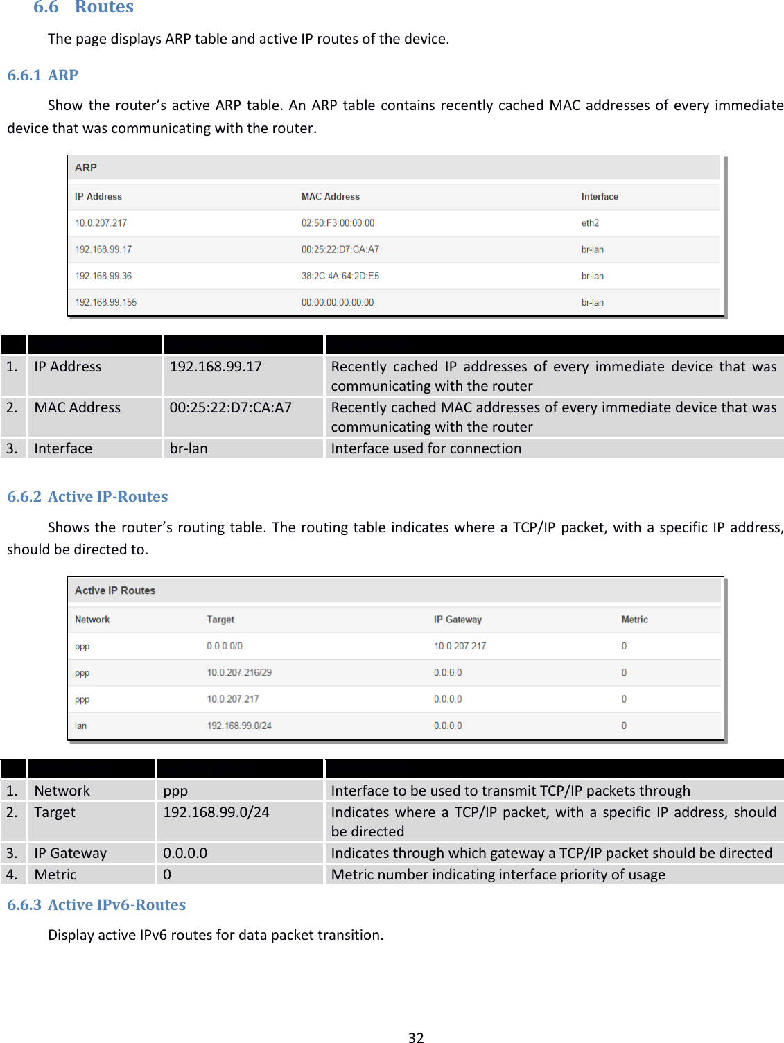
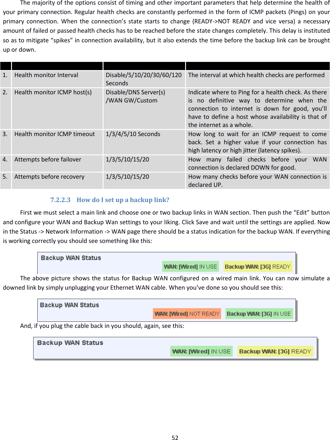
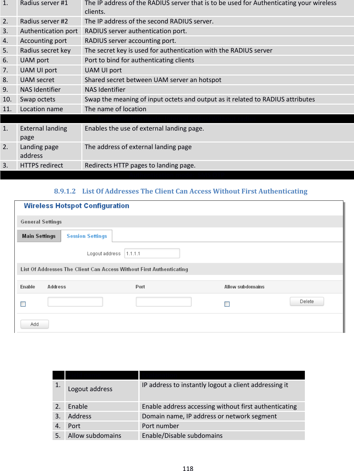
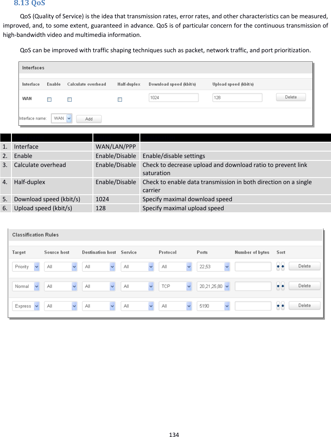
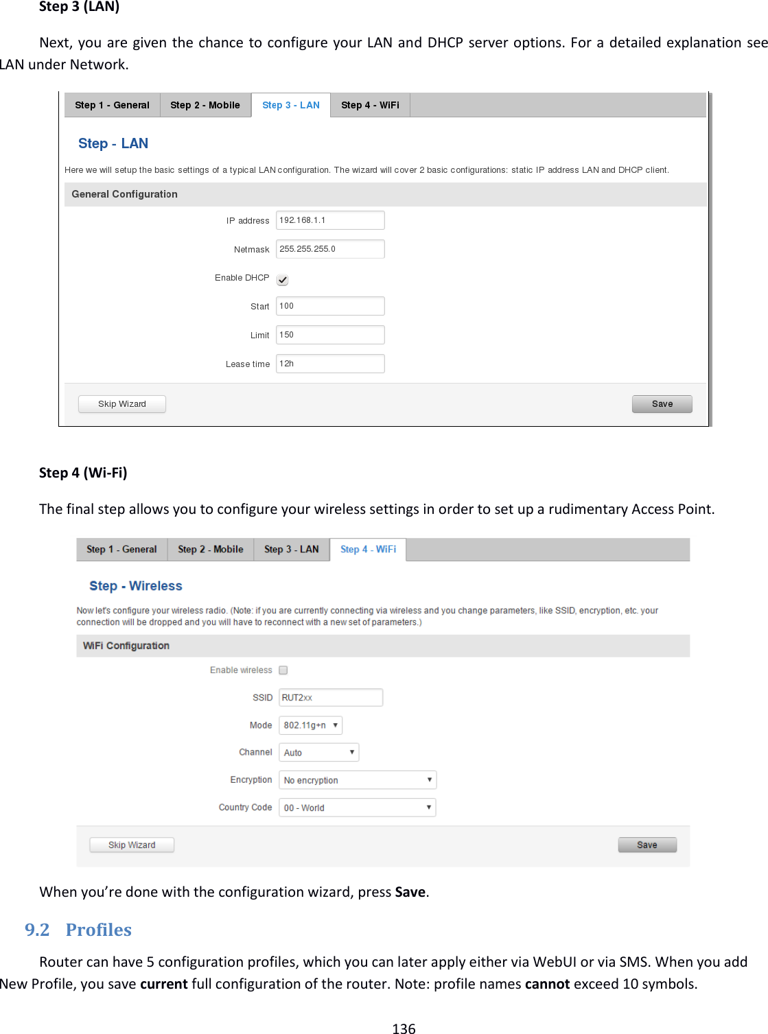
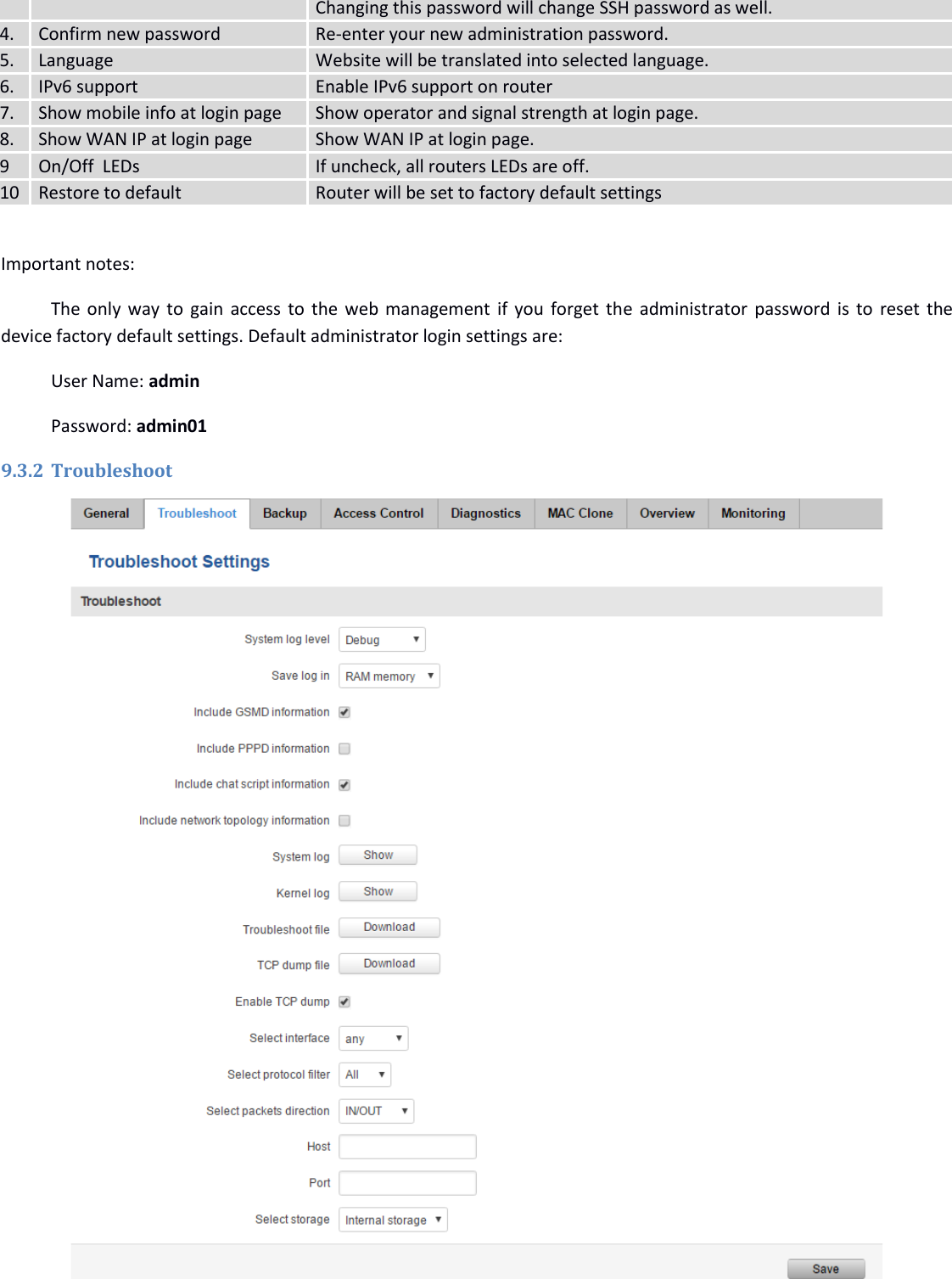
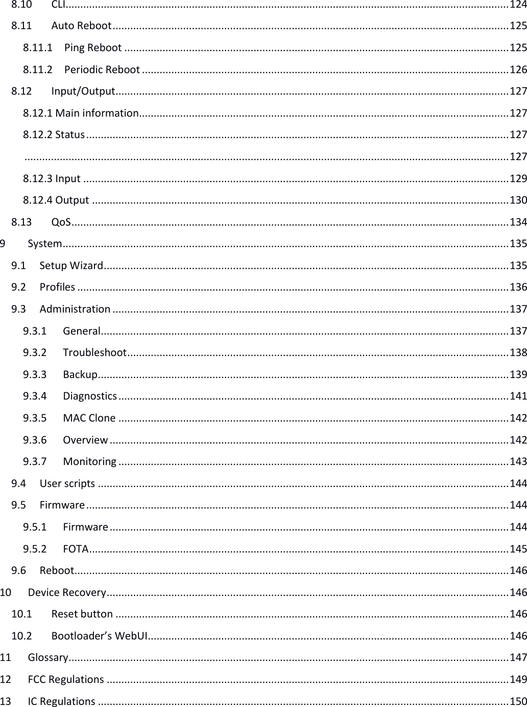
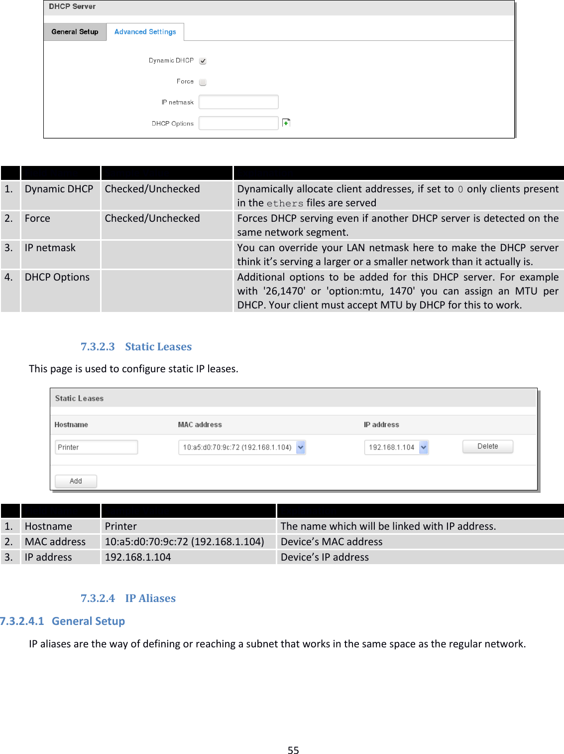
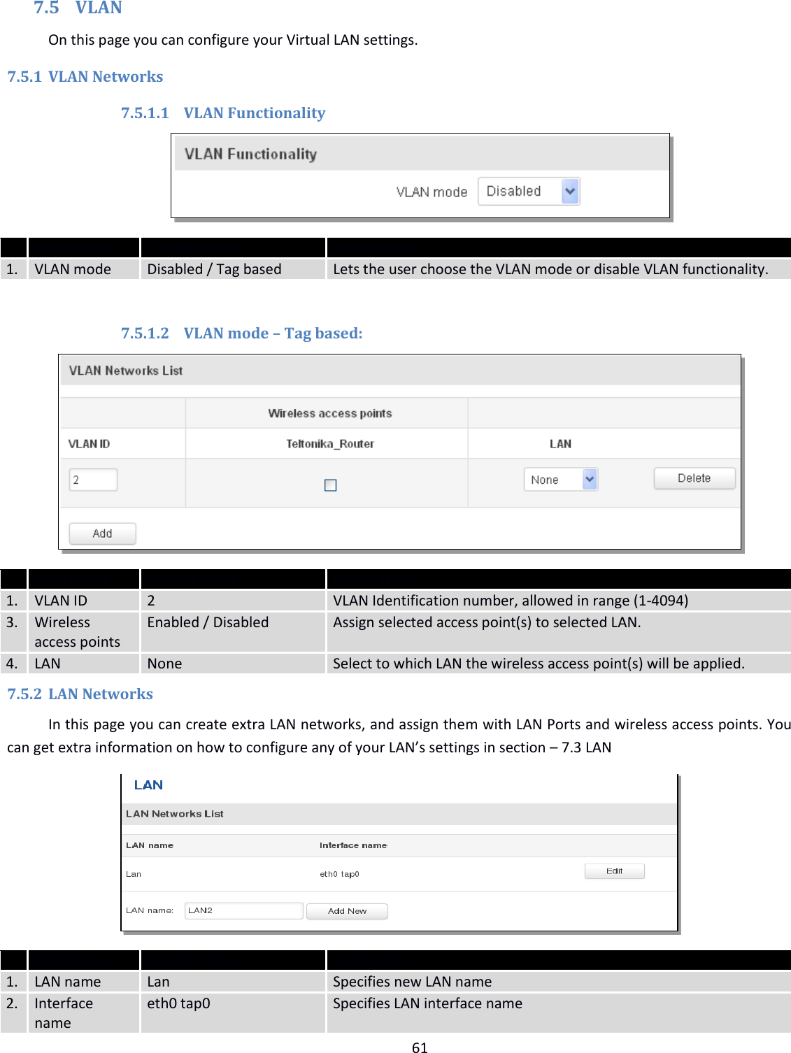
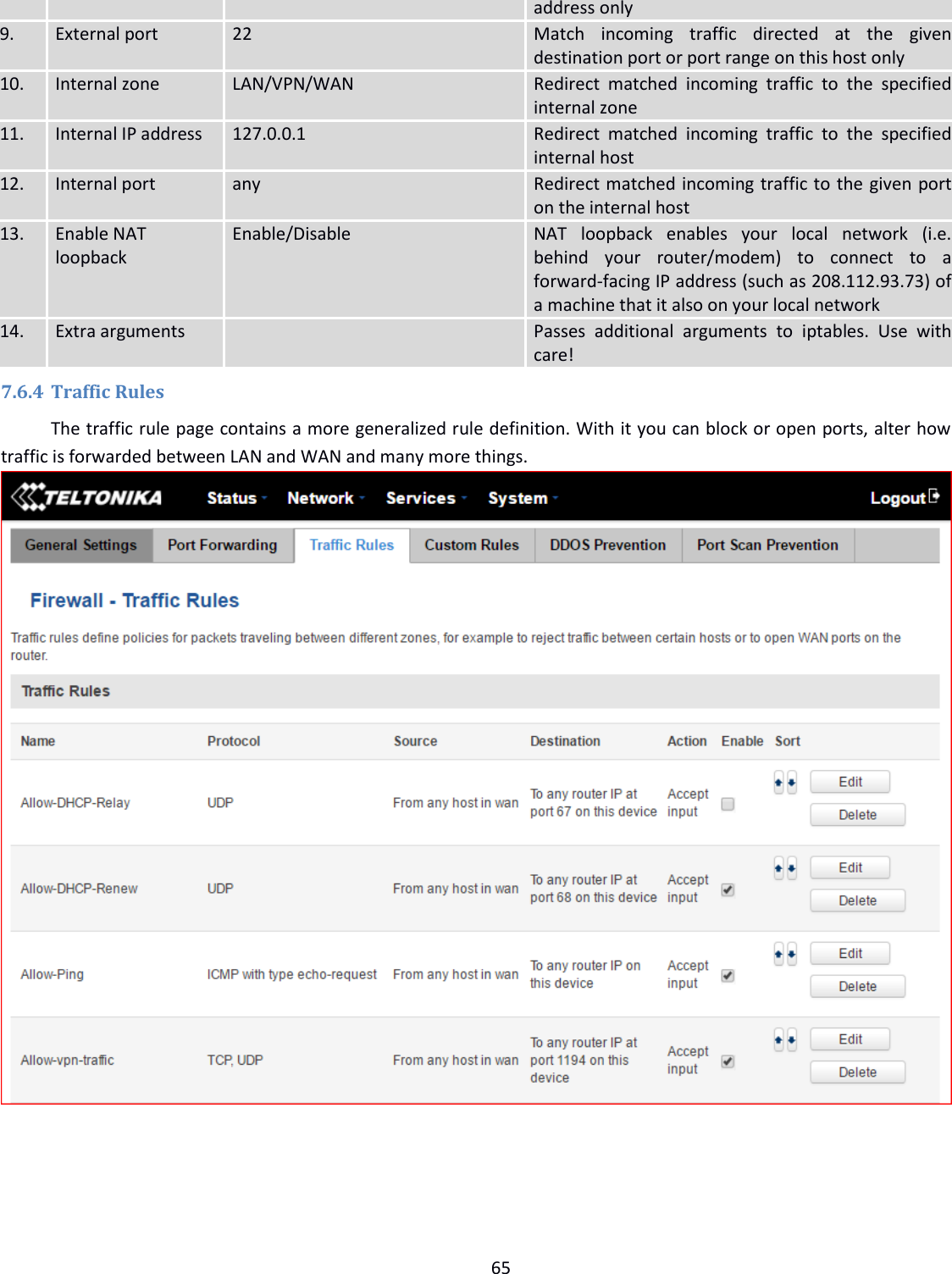
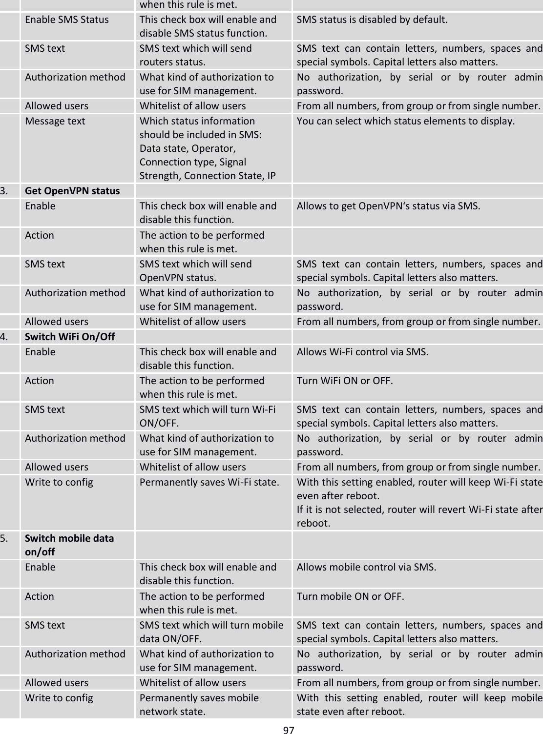
. If the Start value is set to 100 then the DHCP server will only be able to lease out addresses starting from 192.168.2.100 3. Limit 150 How many addresses the DHCP server gets to lease out. Continuing on the above example: if the start address is 192.168.2.100 then the end address will be 192.168.2.254 (100 + 155 – 1 = 254). 4. Lease time 12 How long a leased IP will be considered valid. An IP address after the specified amount of time will expire and the device that leased it out will have to request a new one. Select Hours or Minutes (minimum 2min). 7.3.2.2 Advanced settings You can also define some advanced options that specify how the DHCP server will operate on your LAN network.](https://usermanual.wiki/UAB-Teltonika/RUT240A/User-Guide-3902235-Page-54.png)
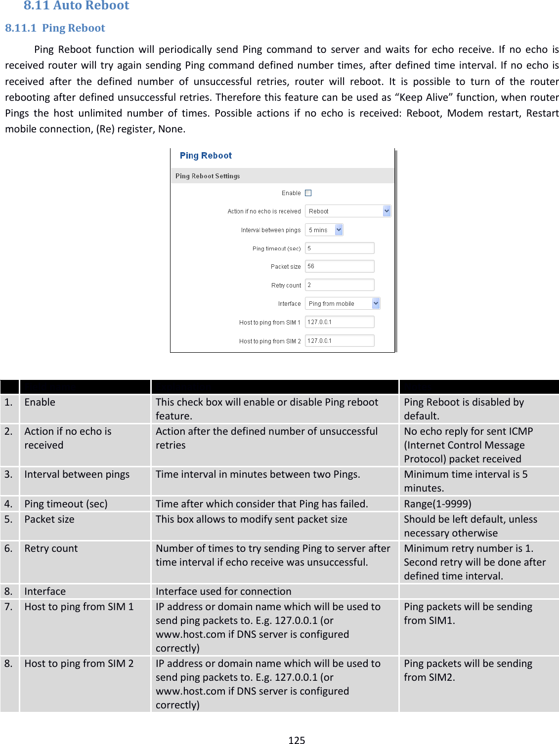
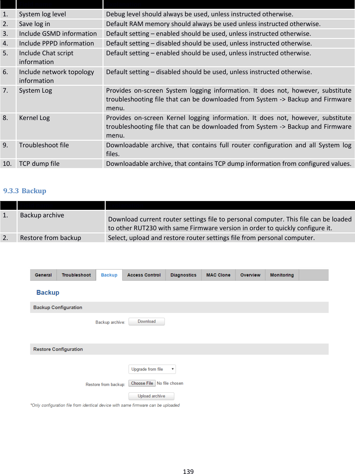
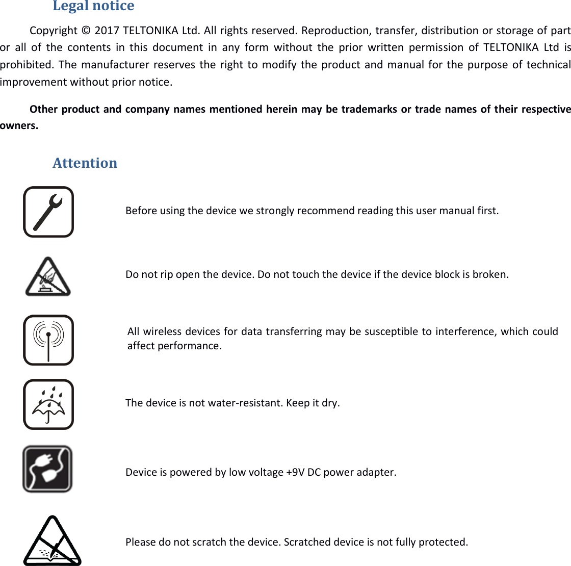
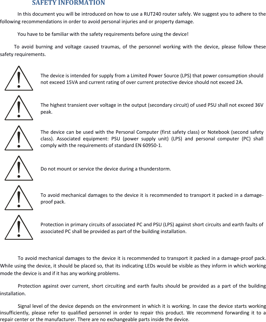
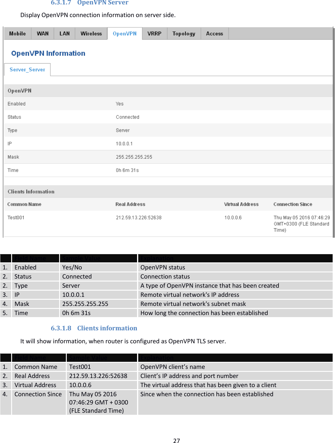
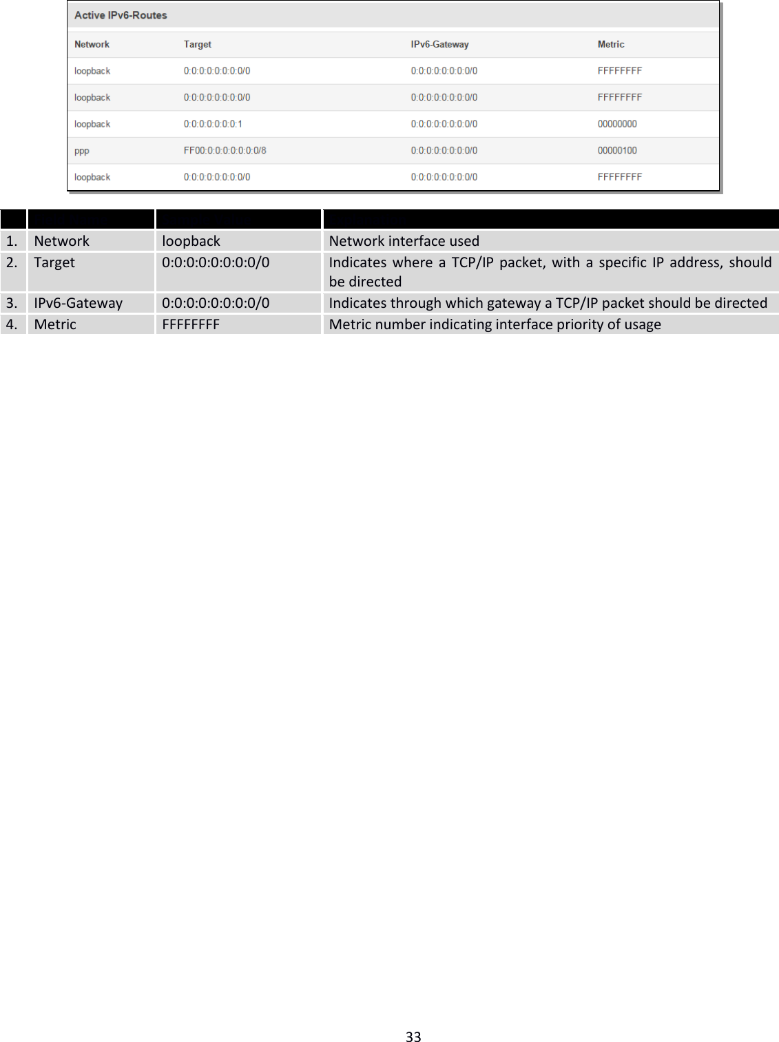
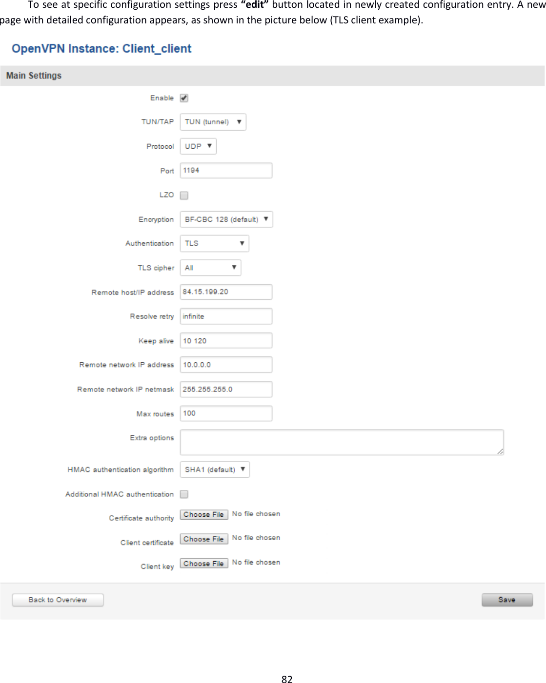
![78 8 Services 8.1 VRRP 8.1.1 VRRP LAN Configuration Settings Field name Sample Explanation 1. Enable Enable/Disable Enable VRRP (Virtual Router Redundancy Protocol) for LAN 2. IP address 192.168.1.253 Virtual IP address for LAN's VRRP (Virtual Router Redundancy Protocol) cluster 3. Virtual ID 1 Routers with same IDs will be grouped in the same VRRP (Virtual Router Redundancy Protocol) cluster, range [1-255] 4. Priority 100 Router with highest priority value on the same VRRP (Virtual Router Redundancy Protocol) cluster will act as a master, range [1-255] 8.1.2 Check Internet connection Field name Sample Explanation 1. Enable Enable/Disable Enable WAN's connection monitoring 2. Ping IP address 8.8.4.4 A host to send ICMP (Internet Control Message Protocol) packets to 3. Ping interval 10 Time interval in seconds between two Pings 4. Ping timeout (sec) 1 Response timeout value, interval [1 - 9999] 5. Ping packet size 50 ICMP (Internet Control Message Protocol) packet's size, interval [0 - 1000] 6. Ping retry count 100 Failed Ping attempt’s count before determining that connection is lost, interval [1 – 9999]](https://usermanual.wiki/UAB-Teltonika/RUT240A/User-Guide-3902235-Page-78.png)
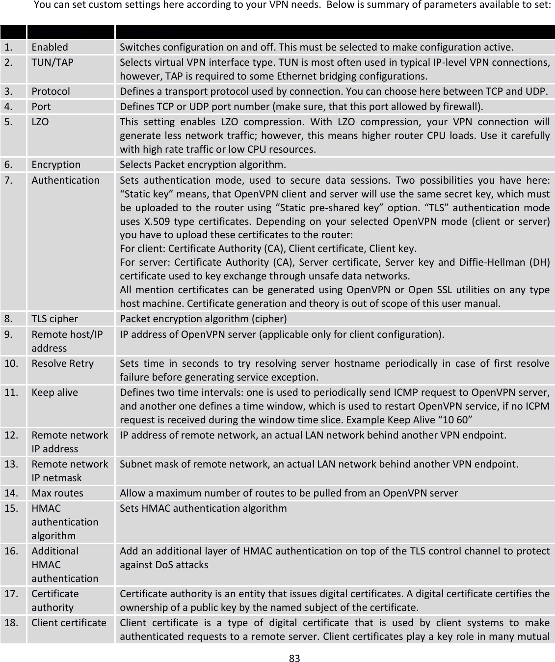

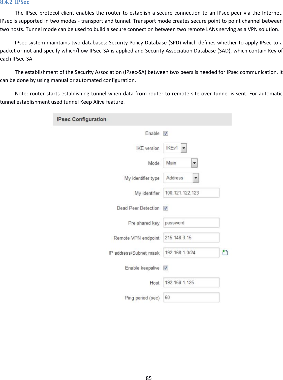
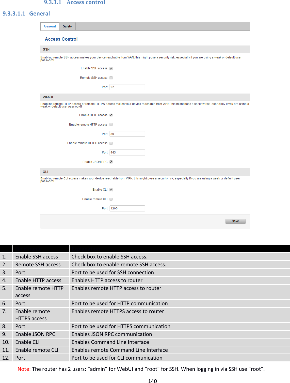
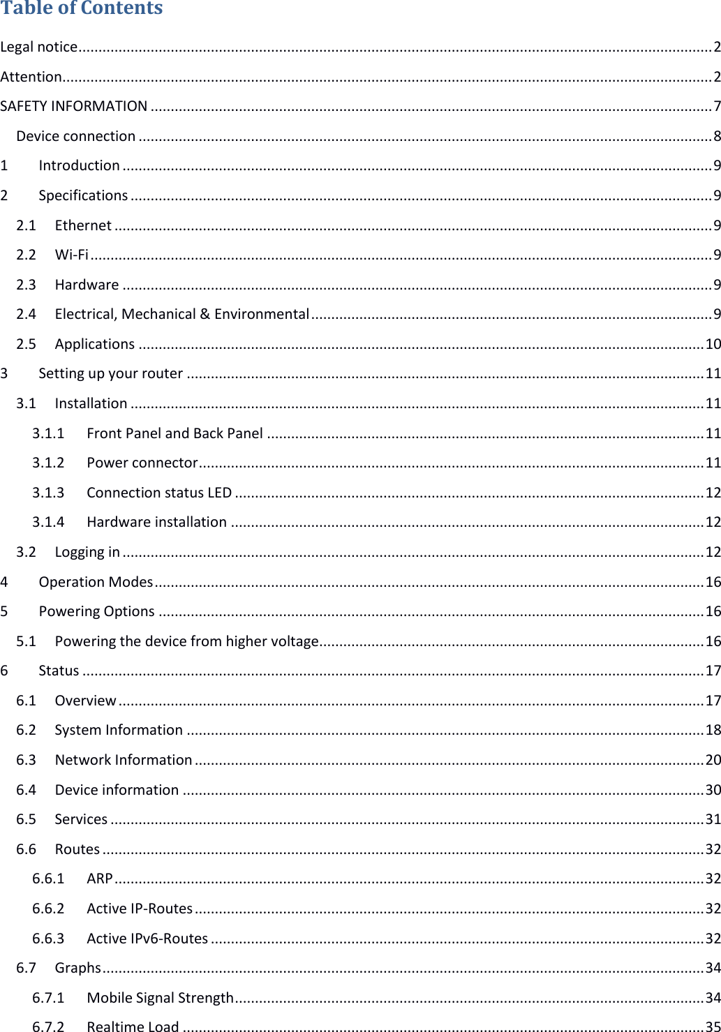
![86 Field name Value Explanation 1. Enable Enabled/Disabled Check box to enable IPSec. 2. IKE version IKEv1 or IKEv2 Method of key exchange 3. Mode “Main” or “Aggressive” ISAKMP (Internet Security Association and Key Management Protocol) phase 1 exchange mode 4. My identifier type Address, FQDN, User FQDN Choose one accordingly to your IPSec configuration 5. My identifier Set the device identifier for IPSec tunnel. In case RUT has Private IP, its identifier should be its own LAN network address. In this way, the Road Warrior approach is possible. 6. Dead Peer Detection Enabled/Disabled The values clear, hold and restart all active DPD 7. Pre shared key A shared password to authenticate between the peer 8. Remote VPN endpoint Domain name or IP address. Leave empty or any 9. IP address/Subnet mask Remote network secure group IP address and mask used to determine to what subnet an IP address belongs to. Range [0-32]. IP should differ from device LAN IP 10. Enable keep alive Enabled/Disabled Enable tunnel keep alive function 11. Host A host address to which ICMP (Internet Control Message Protocol) echo requests will be send 12. Ping period (sec) Send ICMP echo request every x seconds. Range [0-999999] Phase 1 and Phase 2 must be configured accordingly to the IPSec server configuration, thus algorithms, authentication and lifetimes of each phase must be identical.](https://usermanual.wiki/UAB-Teltonika/RUT240A/User-Guide-3902235-Page-86.png)
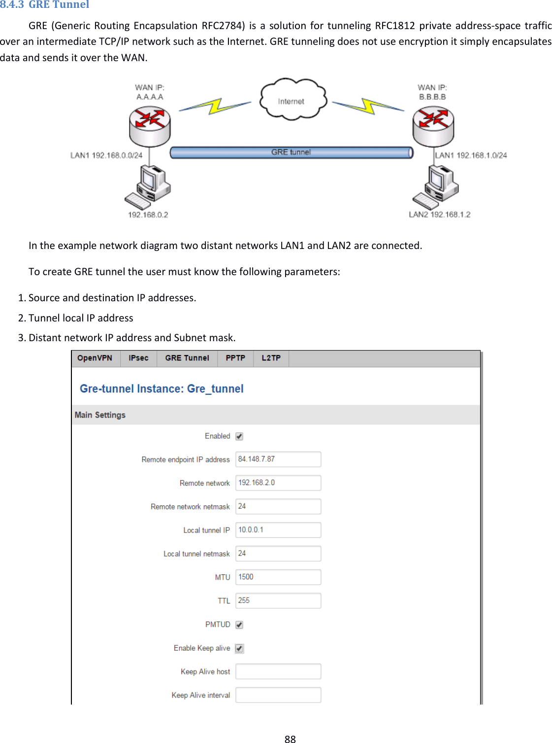
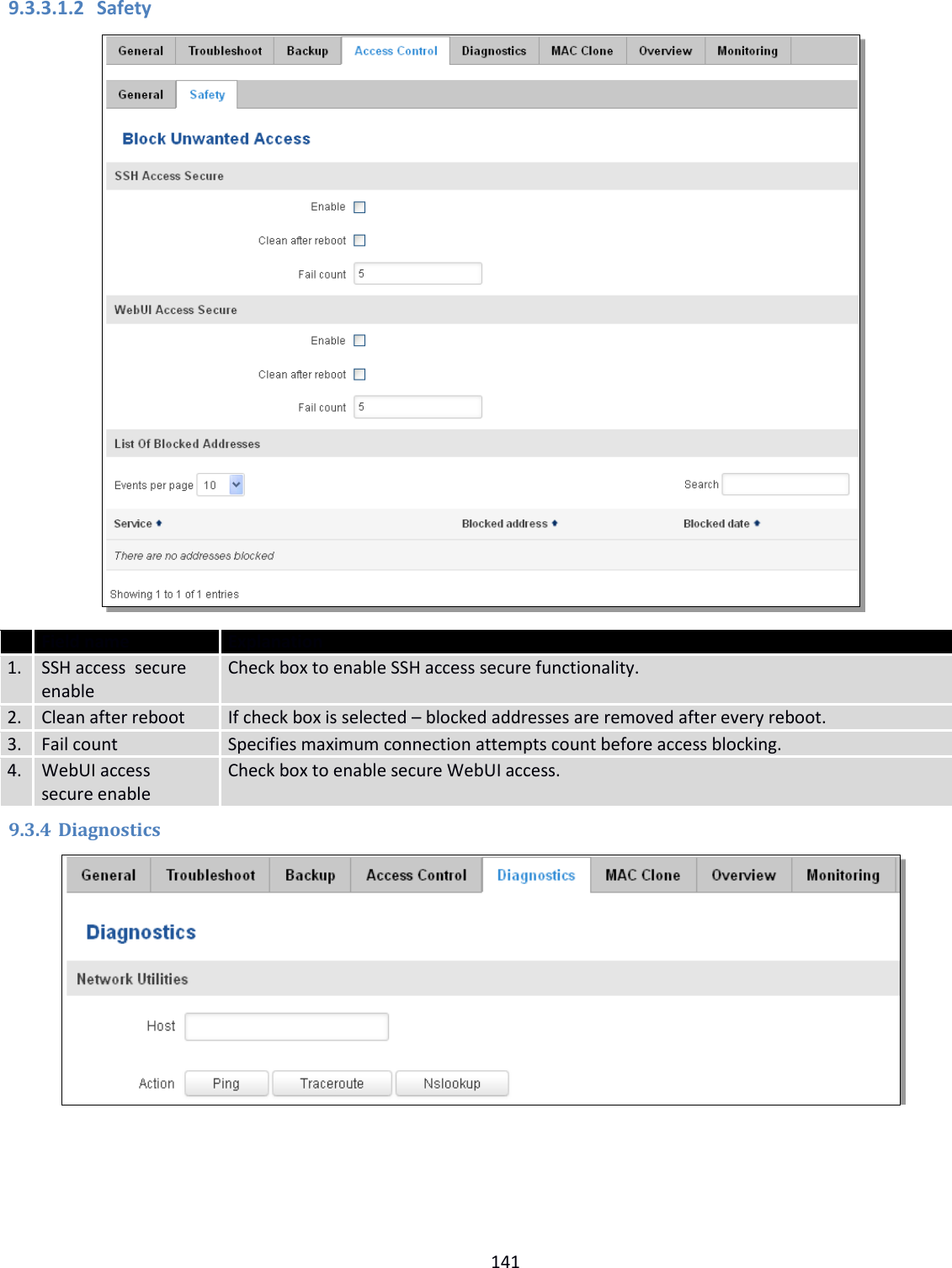
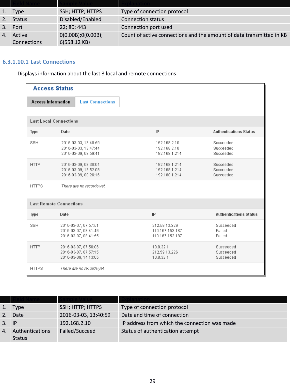
![89 Field name Explanation 1. Enabled Check the box to enable the GRE Tunnel function. 2. Remote endpoint IP address Specify remote WAN IP address. 3. Remote network IP address of LAN network on the remote device. 4. Remote network netmask Network of LAN network on the remote device. Range [0-32]. 5. Local tunnel IP Local virtual IP address. Cannot be in the same subnet as LAN network. 6. Local tunnel netmask Network of local virtual IP address. Range [0-32] 7. MTU Specify the maximum transmission unit (MTU) of a communications protocol of a layer in bytes. 8. TTL Specify the fixed time-to-live (TTL) value on tunneled packets [0-255]. The 0 is a special value meaning that packets inherit the TTL value. 9. PMTUD Check the box to enable the Path Maximum Transmission Unit Discovery (PMTUD) status on this tunnel. 10. Enable Keep alive It gives the ability for one side to originate and receive keep alive packets to and from a remote router even if the remote router does not support GRE keep alive. 11. Keep Alive host Keep Alive host IP address. Preferably IP address which belongs to the LAN network on the remote device. 12. Keep Alive interval Time interval for Keep Alive. Range [0 - 255].](https://usermanual.wiki/UAB-Teltonika/RUT240A/User-Guide-3902235-Page-89.png)
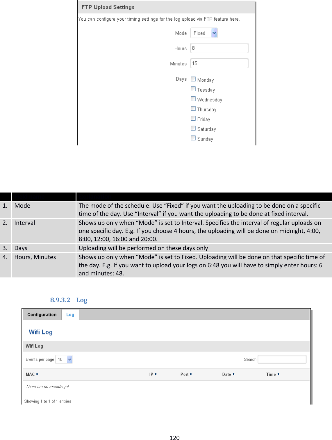
![116 Listed numbers going to be replied. 4. Message “Text” Message text that will be sent in reply. 8.8.4 SMPP Field name Values Explanation 1. Enable Enable/Disable Enables SMPP server 2. User name admin User name for authentication on SMPP server 3. Password ●●●●●●● Password for authentication on SMPP server 4. Server port 7777 A port will be used for SMPP server communications. Allowed all not used ports [0-65535]](https://usermanual.wiki/UAB-Teltonika/RUT240A/User-Guide-3902235-Page-116.png)