UAB Teltonika RUT955A GPS Tracker User Manual Regulatory Guide
UAB Teltonika GPS Tracker Regulatory Guide
Contents
- 1. User Manual 1
- 2. User Manual 2
- 3. User Manual 3
- 4. User Manual - Regulatory Guide
User Manual - Regulatory Guide

1
USER MANUAL
RUT955 LTE Router

2
Legal notice
Copyright © 2015 TELTONIKA Ltd. All rights reserved. Reproduction, transfer, distribution or storage of part
or all of the contents in this document in any form without the prior written permission of TELTONIKA Ltd is
prohibited. The manufacturer reserves the right to modify the product and manual for the purpose of technical
improvement without prior notice.
Other product and company names mentioned herein may be trademarks or trade names of their respective
owners.
Attention
Before using the device we strongly recommend reading this user manual first.
Do not rip open the device. Do not touch the device if the device block is broken.
All wireless devices for data transferring may be susceptible to interference, which could
affect performance.
The device is not water-resistant. Keep it dry.
Device is powered by low voltage +9V DC power adaptor.
Please do not scratch the device. Scratched device is not fully protected.
3
Table of Contents
Legal notice .............................................................................................................................................................. 2
Attention.................................................................................................................................................................. 2
SAFETY INFORMATION ............................................................................................................................................ 9
Device connection ............................................................................................................................................. 10
1 Introduction ................................................................................................................................................. 11
2 Specifications ............................................................................................................................................... 11
2.1 Ethernet ................................................................................................................................................... 11
2.2 Wi-Fi ......................................................................................................................................................... 11
2.3 Hardware ................................................................................................................................................. 11
2.4 Electrical, Mechanical & Environmental .................................................................................................. 12
2.5 Applications ............................................................................................................................................. 12
3 Setting up your router ................................................................................................................................. 13
3.1 Installation ............................................................................................................................................... 13
3.1.1 Front Panel and Back Panel ............................................................................................................. 13
3.1.2 Connection status LED indication .................................................................................................... 13
3.1.3 Hardware installation ...................................................................................................................... 14
3.2 Logging in ................................................................................................................................................. 15
4 Operation Modes ......................................................................................................................................... 18
5 Powering Options ........................................................................................................................................ 19
5.1 Powering the device from higher voltage................................................................................................ 19
6 Status ........................................................................................................................................................... 20
6.1 Overview .................................................................................................................................................. 20
6.2 System Information ................................................................................................................................. 20
6.3 Network Information ............................................................................................................................... 22
6.4 Device information .................................................................................................................................. 30
6.5 Services .................................................................................................................................................... 32
1.1 Routes ...................................................................................................................................................... 32
6.5.1 ARP ................................................................................................................................................... 32
6.5.2 Active IP-Routes ............................................................................................................................... 33
4
6.5.3 Active IPv6-Routes ........................................................................................................................... 33
6.6 Graphs ...................................................................................................................................................... 33
6.6.1 Mobile Signal Strength ..................................................................................................................... 33
6.6.2 Realtime Load .................................................................................................................................. 34
6.6.3 Realtime Traffic ................................................................................................................................ 35
6.6.4 Realtime Wireless ............................................................................................................................ 36
6.6.5 Realtime Connections ...................................................................................................................... 37
6.7 Mobile Traffic ........................................................................................................................................... 38
6.8 Speed Test ................................................................................................................................................ 38
6.9 Events Log ................................................................................................................................................ 39
6.9.1 All Events .......................................................................................................................................... 39
6.9.2 System Events .................................................................................................................................. 40
6.9.3 Network Events ................................................................................................................................ 41
6.9.4 Events Reporting .............................................................................................................................. 42
6.9.5 Reporting Configuration .................................................................................................................. 43
7 Network ....................................................................................................................................................... 46
7.1 Mobile ...................................................................................................................................................... 46
7.1.1 General ............................................................................................................................................. 46
7.1.2 SIM Management ............................................................................................................................ 49
7.1.3 Network Operators .......................................................................................................................... 50
7.1.4 Mobile Data Limit............................................................................................................................. 51
7.1.5 SIM Idle protection .......................................................................................................................... 52
7.2 WAN ......................................................................................................................................................... 53
7.2.1 Operation Mode .............................................................................................................................. 53
7.2.2 Common configuration .................................................................................................................... 54
7.3 LAN ....................................................................................................................................................... 60
7.3.1 Configuration ................................................................................................................................... 60
7.3.2 DHCP Server ..................................................................................................................................... 61
7.4 Wireless ................................................................................................................................................... 63
7.5 VLAN......................................................................................................................................................... 66
7.5.1 VLAN Networks ................................................................................................................................ 66
7.5.2 LAN Networks .................................................................................................................................. 68
7.6 Firewall ..................................................................................................................................................... 68
7.6.1 General Settings ............................................................................................................................... 68
7.6.2 DMZ .................................................................................................................................................. 69
5
7.6.3 Port Forwarding ............................................................................................................................... 69
7.6.4 Traffic Rules...................................................................................................................................... 72
7.6.5 Custom Rules ................................................................................................................................... 76
7.6.6 DDOS Prevention ............................................................................................................................. 76
7.6.7 Port Scan Prevention ....................................................................................................................... 79
7.7 Routing ..................................................................................................................................................... 79
7.7.1 Static Routes .................................................................................................................................... 79
7.7.2 Dynamic Routes ............................................................................................................................... 80
7.8 Load Balancing ......................................................................................................................................... 84
8 Remote monitoring and administration ...................................................................................................... 84
9 Services ........................................................................................................................................................ 86
9.1 VRRP ......................................................................................................................................................... 86
9.1.1 VRRP LAN Configuration Settings .................................................................................................... 86
9.1.2 Check Internet connection ............................................................................................................... 87
9.2 TR-069 ...................................................................................................................................................... 87
9.2.1 TR-069 Parameters Configuration ................................................................................................... 87
9.3 Web filter ................................................................................................................................................. 88
9.3.1 Site blocking ..................................................................................................................................... 88
9.3.2 Proxy Based Content Blocker ........................................................................................................... 88
9.4 NTP ........................................................................................................................................................... 89
9.5 RS232/RS485 ............................................................................................................................................ 91
9.5.1 RS232 ............................................................................................................................................... 91
9.5.2 RS485 ............................................................................................................................................... 93
9.5.3 Modes of different serial types in RS232 and RS485 ....................................................................... 96
9.6 VPN ........................................................................................................................................................ 100
9.6.1 OpenVPN ........................................................................................................................................ 100
9.6.2 IPSec ............................................................................................................................................... 103
9.6.3 GRE Tunnel ..................................................................................................................................... 106
9.6.4 PPTP ............................................................................................................................................... 108
9.6.5 L2TP ................................................................................................................................................ 109
9.7 Dynamic DNS .......................................................................................................................................... 109
9.8 SMS Utilities ........................................................................................................................................... 111
9.8.1 SMS Utilities ................................................................................................................................... 111
9.8.2 Call Utilities .................................................................................................................................... 118
9.8.3 User Groups ................................................................................................................................... 119
6
9.8.4 SMS Management .......................................................................................................................... 119
9.8.5 Remote Configuration .................................................................................................................... 121
9.8.6 Statistics ......................................................................................................................................... 124
9.9 SNMP ..................................................................................................................................................... 124
9.9.1 SNMP Settings ................................................................................................................................ 125
9.9.2 TRAP Settings ................................................................................................................................. 126
9.10 SMS Gateway ..................................................................................................................................... 126
9.10.1 Post/Get Configuration ................................................................................................................. 126
9.10.2 Email to SMS .................................................................................................................................. 128
9.10.3 Scheduled Messages ..................................................................................................................... 129
9.10.4 Auto Reply Configuration .............................................................................................................. 129
9.10.5 SMS Forwarding............................................................................................................................. 130
9.10.6 SMPP .............................................................................................................................................. 133
9.11 GPS ..................................................................................................................................................... 133
9.11.1 GPS ................................................................................................................................................. 133
9.11.2 GPS Settings ................................................................................................................................... 134
9.11.3 GPS Mode ...................................................................................................................................... 134
9.11.4 GPS I/O .......................................................................................................................................... 135
9.11.5 GPS Geofencing ............................................................................................................................. 136
9.12 Hotspot .............................................................................................................................................. 137
9.12.1 General settings ............................................................................................................................. 137
9.12.2 Internet Access Restriction Settings .............................................................................................. 139
9.12.3 Logging........................................................................................................................................... 140
9.12.4 Landing Page .................................................................................................................................. 141
9.12.5 Radius server configuration ........................................................................................................... 143
9.12.6 Statistics ......................................................................................................................................... 144
9.13 CLI....................................................................................................................................................... 144
9.14 Auto Reboot ....................................................................................................................................... 145
9.14.1 Ping Reboot ................................................................................................................................... 145
9.14.2 Periodic Reboot ............................................................................................................................. 146
9.15 UPNP .................................................................................................................................................. 146
9.15.1 General Settings ............................................................................................................................ 146
9.15.2 Advanced Settings ......................................................................................................................... 146
9.15.3 UPnP ACLs ...................................................................................................................................... 147
9.15.4 Active UPnP Redirects ................................................................................................................... 147

7
9.16 QoS ..................................................................................................................................................... 147
9.17 Network Shares .................................................................................................................................. 148
9.17.1 Mounted File Systems ................................................................................................................... 148
9.17.2 Samba ............................................................................................................................................ 149
9.17.3 Samba User .................................................................................................................................... 149
9.18 Input/Output ...................................................................................................................................... 151
9.18.1 Status ............................................................................................................................................. 151
9.18.2 Input .............................................................................................................................................. 151
9.18.3 Output ........................................................................................................................................... 154
9.18.4 Input/Output hardware information............................................................................................. 157
9.19 MQTT ................................................................................................................................................. 163
9.20 Modbus TCP interface ........................................................................................................................ 168
10 System ........................................................................................................................................................ 169
10.1 Configuration Wizard ......................................................................................................................... 169
10.2 Profiles ............................................................................................................................................... 171
10.3 Administration ................................................................................................................................... 172
10.3.1 General .......................................................................................................................................... 172
10.3.2 Troubleshoot ................................................................................................................................. 173
10.3.3 Backup ........................................................................................................................................... 174
10.3.4 Diagnostics ..................................................................................................................................... 176
10.3.5 MAC Clone ..................................................................................................................................... 177
10.3.6 Overview ........................................................................................................................................ 177
10.3.7 Monitoring ..................................................................................................................................... 178
10.4 User scripts ........................................................................................................................................ 178
10.5 Restore point ..................................................................................................................................... 179
10.5.1 Restore point create ...................................................................................................................... 179
10.5.2 Restore point load ......................................................................................................................... 179
10.6 Firmware ............................................................................................................................................ 180
10.6.1 Firmware........................................................................................................................................ 180
10.6.2 FOTA .............................................................................................................................................. 181
10.7 Reboot ................................................................................................................................................ 181
11 Device Recovery ......................................................................................................................................... 181
11.1 Reset button ...................................................................................................................................... 182
11.2 Bootloader’s WebUI ........................................................................................................................... 182
12 Glossary:..................................................................................................................................................... 182
8
13 Changelog .................................................................................................................................................. 185

9
SAFETY INFORMATION
In this document you will be introduced on how to use a router safely. We suggest you to adhere to the
following recommendations in order to avoid personal injuries and or property damage.
You have to be familiar with the safety requirements before using the device!
To avoid burning and voltage caused traumas, of the personnel working with the device, please follow these
safety requirements.
The device is intended for supply from a Limited Power Source (LPS) that power consumption
should not exceed 15VA and current rating of overcurrent protective device should not exceed 2A.
The highest transient overvoltage in the output (secondary circuit) of used PSU shall not
exceed 36V peak.
The device can be used with the Personal Computer (first safety class) or Notebook (second
safety class). Associated equipment: PSU (power supply unit) (LPS) and personal computer (PC) shall
comply with the requirements of standard EN 60950-1.
Do not mount or service the device during a thunderstorm.
To avoid mechanical damages to the device it is recommended to transport it packed in a
damage-proof pack.
Protection in primary circuits of associated PC and PSU (LPS) against short circuits and earth
faults of associated PC shall be provided as part of the building installation.
To avoid mechanical damages to the device it is recommended to transport it packed in a damage-proof pack.
While using the device, it should be placed so, that its indicating LEDs would be visible as they inform in which working
mode the device is and if it has any working problems.
Protection against overcurrent, short circuiting and earth faults should be provided as a part of the building
installation.
Signal level of the device depends on the environment in which it is working. In case the device starts working
insufficiently, please refer to qualified personnel in order to repair this product. We recommend forwarding it to a
repair center or the manufacturer. There are no exchangeable parts inside the device.
10
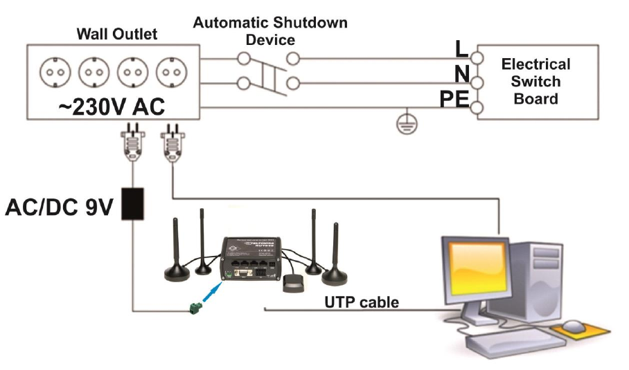
Device connection
11
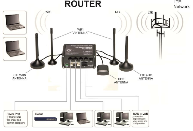
1 Introduction
Thank you for purchasing a RUT955 LTE router!
RUT955 is part of the RUT9xx series of compact mobile routers with high speed wireless and Ethernet
connections.
This router is ideal for people who‘d like to share their internet on the go, as it is not restricted by a cumbersome
cable connection. Unrestricted, but not forgotten: the router still supports internet distribution via a broadband cable,
simply plug it in to the wan port, set the router to a correct mode and you are ready to browse.
2 Specifications
2.1 Ethernet
IEEE 802.3, IEEE 802.3u standards
3 x LAN 10/100Mbps Ethernet ports
1 x WAN 10/100Mbps Ethernet port
Supports Auto MDI/MDIX
2.2 Wi-Fi
IEEE 802.11b/g/n WiFi standards
2x2 MIMO
AP and STA modes
64/128-bit WEP, WPA, WPA2, WPA&WPA2 encryption methods
2.401 – 2.495GHz Wi-Fi frequency range*
20dBm max WiFi TX power
SSID stealth mode and access control based on MAC address
*Supported frequency bands are dependent on geographical location and may not be available in all markets.
2.3 Hardware
High performance 560 MHz CPU with 128 Mbytes of DDR2 memory
2 pin industrial DC power socket
Attachable DIN rail adapter
4 pin industrial socket for 2/4 wire RS485
DB9 socket for full-featured RS232
USB A socket for external devices4 pin industrial socket for 2/4 wire RS485
Reset/restore to default button
2 x SMA for LTE , 2 x RP-SMA for WiFi antenna connectors
4 x Ethernet LEDs, 1 x Power LED
1 x bi-color connection status LED, 5 x connection strength LEDs
10 pin industrial socket for inputs/outputs:
- 0 - 3 V digital input
- 0 - 30 V digital galvanically isolated input
- 0 - 24 V analog input 30 V, 250 mA digital open collector output
- 40 V, 4 A SPST relay output
12
2.4 Electrical, Mechanical & Environmental
Dimensions (H x W x D) 80mm x 106mm x 46mm
Weight 250g
Power supply 100 – 240 VAC -> 9 VDC wall adapter
Input voltage range 9 – 30VDC
Power consumption < 7W
Operating temperature -40° to 75° C
Storage temperature -45° to 80° C
Operating humidity 10% to 90% Non-condensing
Storage humidity 5% to 95% Non-condensing
2.5 Applications
13
3 Setting up your router
3.1 Installation
After you unpack the box, follow the steps, documented below, in order to properly connect the device. For
better Wi-Fi performance, put the device in clearly visible spot, as obstacles such as walls and door hinder the signal.
1. First assemble your router by attaching the necessary antennas and inserting the SIM card.
2. To power up your router, please use the power adapter included in the box. (IMPORTANT: Using a different
power adapter can damage and void the warranty for this product.).
3. If you have a wired broadband connection you will also have to connect it to the WAN port of the router.
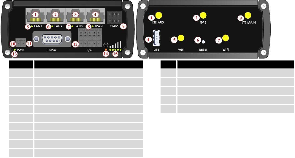
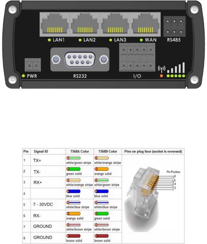
3.1.1 Front Panel and Back Panel
1,2,3
LAN Ethernet ports
1
LTEauxiliary antenna connector
4
WAN Ethernet port
2
GPS antenna connector
5,6,7
LAN LEDs
3
LTE main antenna connector
8
WAN LED
4
USB connector
9
RS485 connector
5,7
WiFi antenna connectors
10
Power socket
6
Reset button
11
RS232 connector
12
Inputs and outputs connector
13
Power LED
14
Connection LED
15
Signal strength LED
3.1.2 Connection status LED indication
Constant blinking (~ 2Hz) – router is turning on.
LED turned off – it has no 4G data connection
LED turned on – it has 4G data connection.
Explanation of connection status LED indication:
1. Green and red blinking alternatively ever 500 ms: no SIM or bad PIN;
2. Green, red and yellow blinking alternatively every 500 ms: connecting to GSM;
3. Red blinking every 1 sec: connected 2G, but no data session established;
4. Yellow blinking every 1 sec: connected 3G, no data session established;
5. Green blinking every 1 sec: connected 4G, no data session established;
Red lit and blinking rapidly while data is being transferred: connected 2G with data session;
Yellow lit and blinking rapidly while data is being transferred: connected 3G with data session;
Green lit and blinking rapidly while data is being transferred: connected 4G with data session;
14
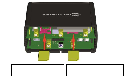
3.1.3 Hardware installation
1. Remove back panel and insert SIM card which was given by your ISP (Internet Service Provider). Correct SIM card
orientation is shown in the picture.
2. Attach LTE main and Wi-Fi antennas.
3. Connect the power adapter to the socket on the front panel of the device. Then plug the other end of the power
adapter into a wall outlet or power strip.
4. Connect to the device wirelessly (SSID: Teltonika_Router) or use Ethernet cable and plug it into any LAN Ethernet
port.
SIM 1 (primary)
SIM 2 (secondary)
15
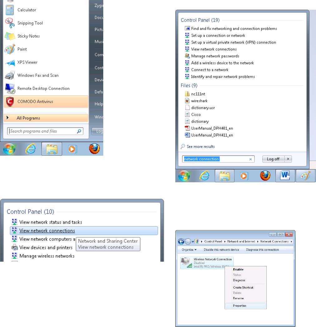
3.2 Logging in
After you’re complete with the setting up as described in the section above, you are ready to start logging into
your router and start configuring it. This example shows how to connect on Windows 7. On windows Vista: click Start ->
Control Panel -> Network and Sharing Centre -> Manage network Connections -> (Go to step 4). On Windows XP: Click
Start -> Settings -> Network Connections -> (see step 4). You wont’s see “Internet protocol version 4(TCP/IPv4)”, instead
you’ll have to select “TCP/IP Settings” and click options -> (Go to step 6)
We first must set up our network card so that it could properly communicate with the router.
1. Press the start button
2. Type in “network connections”, wait for the results to
pop up.
3. Click “View network connections”
4. Then right click on your wireless device that you use to
connect to other access points (It is the one with the name
“Wireless Network Connection” and has signal bars on its
icon).
16
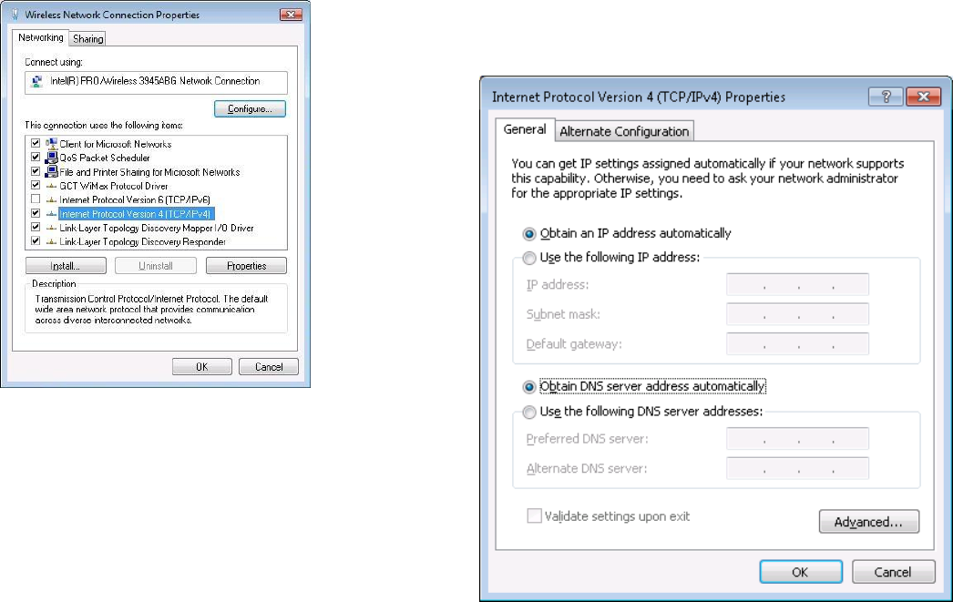
5. Select Internet Protocol Version 4 (TCP/IPv4) and then click
Properties
6. By default the router is going to have DHCP enabled,
which means that if you select “Obtain an IP address
automatically” and “Obtain DNS server address
automatically”, the router should lease you an IP and you
should be ready to login.
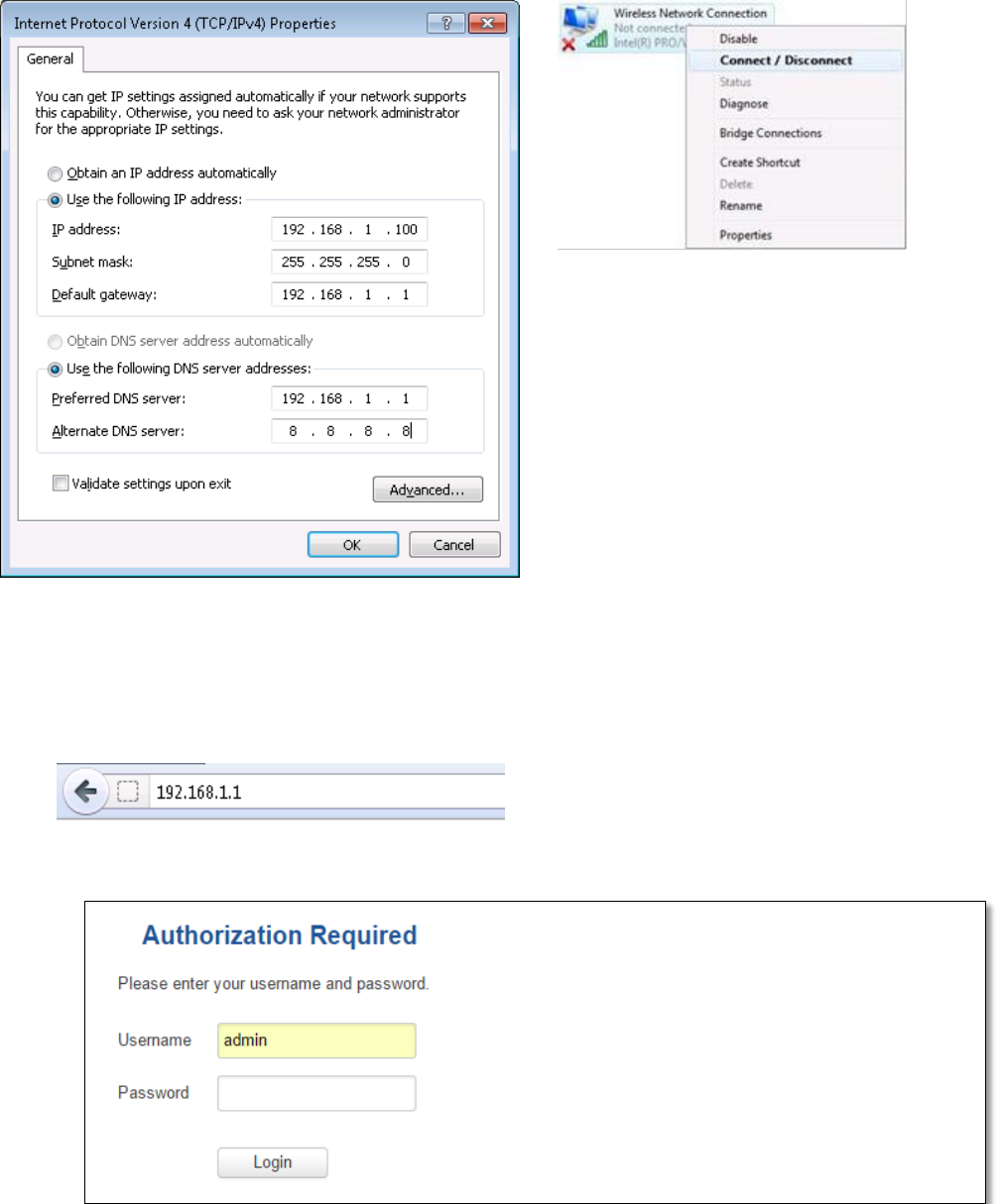
7. If you choose to configure manually here’s what you do:
First select an IP address. Due to the stock settings that your router has arrived in you can only enter an IP in the
form of 192.168.1.XXX , where XXX is a number in the range of 2-254 (192.168.1.2 , 192.168.1.254 , 192.168.1.155 and
so on… are valid; 192.168.1.0 , 192.168.1.1 , 192.168.1.255 , 192.168.1.699 and so on… are not). Next we enter the
subnet mask: this has to be “255.255.255.0”. Then we enter the default gateway: this has to be “192.168.1.1”. Finally we
enter primary and secondary DNS server IPs. One will suffice, though it is good to have a secondary one as well as it will
act as a backup if the first should fail. The DNS can be your routers IP (192.168.1.1), but it can also be some external DNS
server (like the one Google provides: 8.8.8.8).
17
Right click on the Wireless network icon and select Connect / Disconnect. A list should pop up with all available
wireless networks. Select “Teltonika” and click connect.Then we launch our favorite browser and enter the routers IP
into the address field:
Press enter. If there are no problems you should be greeted with a login screen such as this:
Enter the default password, which is “admin01” into the “Password” field and then either click Login with your
mouse or press the Enter key. You have now successfully logged into the RUT955!
From here on out you can configure almost any aspect of your router.

18
4 Operation Modes
The RUT9xx series router supports various operation modes. It can be connected to the internet (WAN) via
mobile, standard Ethernet cable or via a wireless network. When connecting to the internet, you may also backup your
main WAN connection with one or two backup connections. Any interface can act like backup if configured so. At first
router uses its main WAN connection, if it is lost then router tries to connect via backup with higher priority and if that
fails too, router tries the second backup option.
WAN
Main WAN
Backup WAN
LAN
Mobile
√
√
x
Ethernet
√
√
√
Wi-Fi
√
√
√
In later sections it will be explained, in detail, how to configure your router to work in a desired mode.
19
5 Powering Options
The RUT9xx router can be powered from power socket or over Ethernet port. Depending on your network
architecture you can use LAN 1 port to power the device.
RUT9xx can be powered from power socket and over Ethernet simultaneously. Power socket has higher priority
meaning that the device will draw power from power socket as long as it is available.
When RUT9xx is switching from one power source to the other it loses power for a fraction of the second and
may reboot. The device will function correctly after the reboot.
Though the device can be powered over Ethernet port it is not compliant with IEEE 802.3af-2003 standard.
Powering RUT9xx from IEEE 802.3af-2003 power supply will damage the device as it is not rated for input voltages of
PoE standard.
5.1 Powering the device from higher voltage
If you decide not to use our standard 9 VDC wall adapters and want to power the device from higher voltage (15 –
30 VDC) please make sure that you choose power supply of high quality. Some power supplies can produce voltage
peaks significantly higher than the declared output voltage, especially during connecting and disconnecting them.
While the device is designed to accept input voltage of up to 30 VDC peaks from high voltage power supplies can
harm the device. If you want to use high voltage power supplies it is recommended to also use additional safety
equipment to suppress voltage peaks from power supply.
20
6 Status
The status section contains various information, like current IP addresses of various network interfaces; the state
of the routers memory; firmware version; DHCP leases; associated wireless stations; graphs indicating load, traffic, etc.;
and much more.
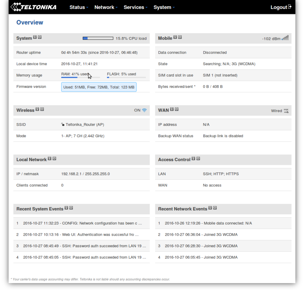
6.1 Overview
O Overview section contains various information summaries.
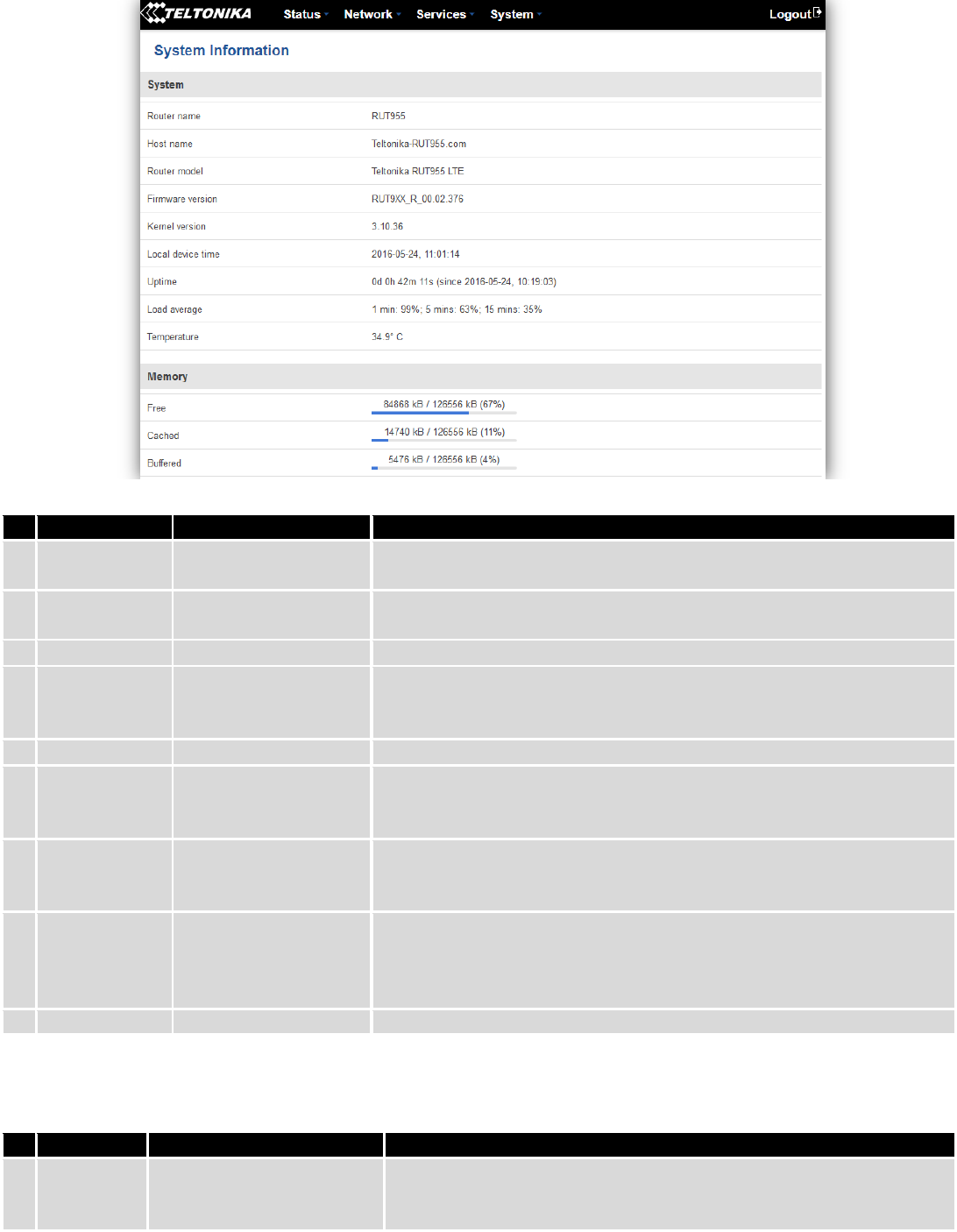
6.2 System Information
The System Information tab contains data that pertains to the routers operating system.
21
System explanation:
Field Name
Sample value
Explanation
1.
Router Name
RUT955
Name of the router (hostname of the routers system). Can be changed
in System -> Administration.
2.
Host name
Teltonika-RUT955.com
Indicates how router will be seen by other devices on the network. Can
be changed in System -> Administration.
3.
Router Model
Teltonika RUT955 LTE
Routers model.
4.
Firmware
Version
RUT9XX_R_00.02.376
Shows the version of the firmware that is currently loaded in the router.
Newer versions might become available as new features are added. Use
this field to decide whether you need a firmware upgrade or not.
5.
Kernel Version
3.10.36
The version of the Linux kernel that is currently running on the router.
6.
Local Time
2016-05-24, 11:02:39
Shows the current system time. Might differ from your computer,
because the router synchronizes it's time with an NTP server.Format
[year-month-day, hours:minutes:seconds].
7.
Uptime
0d 0h 44m 1s (since
2016-05-24, 10:19:03)
Indicates how long it has been since the router booted up. Reboots will
reset this timer to 0.Format *day’s hours minutes seconds (since year-
month-day, hours: minutes: seconds)].
8.
Load Average
1 min: 88%; 5 mins:
73%; 15 mins: 42%
Indicates how busy the router is. Let's examine some sample output: "1
min: 88%, 5 mins: 73%, 15 mins: 42%". The first number mean past
minute and second number means that in the past minute there have
been, on average, 88% processes running or waiting for a resource.
9.
Temperature
34.9° C
Device’s temperature
Memory explanation:
Field Name
Sample Value
Explanation
1.
Free
84584 kB /126556 kB (66%)
The amount of memory that is completely free. Should this rapidly
decrease or get close to 0, it would indicate that the router is running
out of memory, which could cause crashes and unexpected reboots.
22
2.
Cached
14784 kB /126556 kB (11%)
The size of the area of memory that is dedicated to storing frequently
accessed data.
3.
Buffered
5504 kB / 126556 kB (4%)
The size of the area in which data is temporarily stored before moving
it to another location.
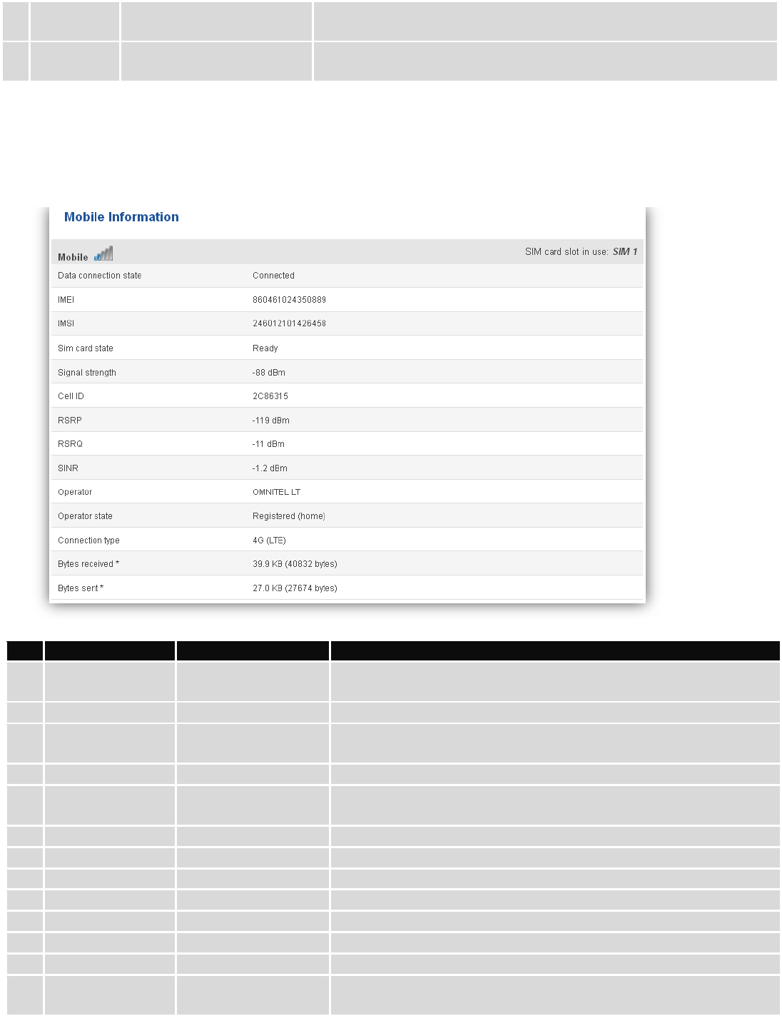
6.3 Network Information
6.3.1.1 Mobile
Display information about mobile modem connections.
Mobile information:
Field Name
Sample Value
Explanation
1.
Data connection
state
Connected
Mobile data connection status
2.
IMEI
860461024350889
Modem's IMEI (International Mobile Equipment Identity) number
3.
IMSI
246012101426458
IMSI (International Mobile Subscriber Identity) is used to identify
the user in a cellular network
4.
SIM card state
Ready
Indicates the SIM card's state, e.g. PIN required, Not inserted, etc.
5.
Signal strength
-88 dBm
Received Signal Strength Indicator (RSSI). Signal's strength
measured in dBm
6.
Cell ID
2C86315
ID of operator cell that device is currently connected to
7.
RSRP
-119 dBm
Indicates the Reference Signal Received Power
8.
RSRQ
-11 dBm
Indicates the Reference Signal Received Quality
9.
SINR
-1.2 dBm
Indicates the Signal to Interference plus Noise Ratio
10.
Operator
OMNITEL LT
Operator's name of the connected GSM network
11.
Operator state
Registered (home)
GSM network's status
12.
Connection type
4G (LTE)
Indicates the GSM network's access technology
13.
Bytes received
39.9 KB (40832
bytes)
How many bytes were received via mobile data connection
23
14.
Bytes sent
27.0 KB (27674
bytes)
How many bytes were sent via mobile data connection
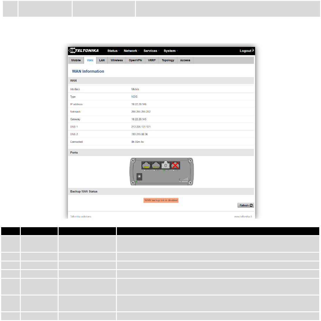
6.3.1.2 WAN
Display information about WAN connection.
WAN information:
Field Name
Sample Value
Explanation
1.
Interface
Mobile
Specifies through what medium the router is connecting to the internet.
This can either be Wired, Mobile or Wi-Fi.
2.
Type
NDIS
Specifies the type of connection. This can either be static or DHCP.
3.
IP address
10.22.20.146
The IP address that the routers uses to connect the internet.
5.
Netmask*
255.255.255.252
Specifies a mask used to define how large the WAN network is
6.
Gateway*
10.22.20.145
Indicates the default gateway, an address where traffic destined for the
internet is routed to.
7.
DNS*
213.226.131.131 /
193.219.88.36
Domain name server(s).
8.
Connected*
0h 56m 4s
How long the connection has been successfully maintained.
*-These fields show up on other connection modes.
**-Exclusive to other Modes with DHCP.
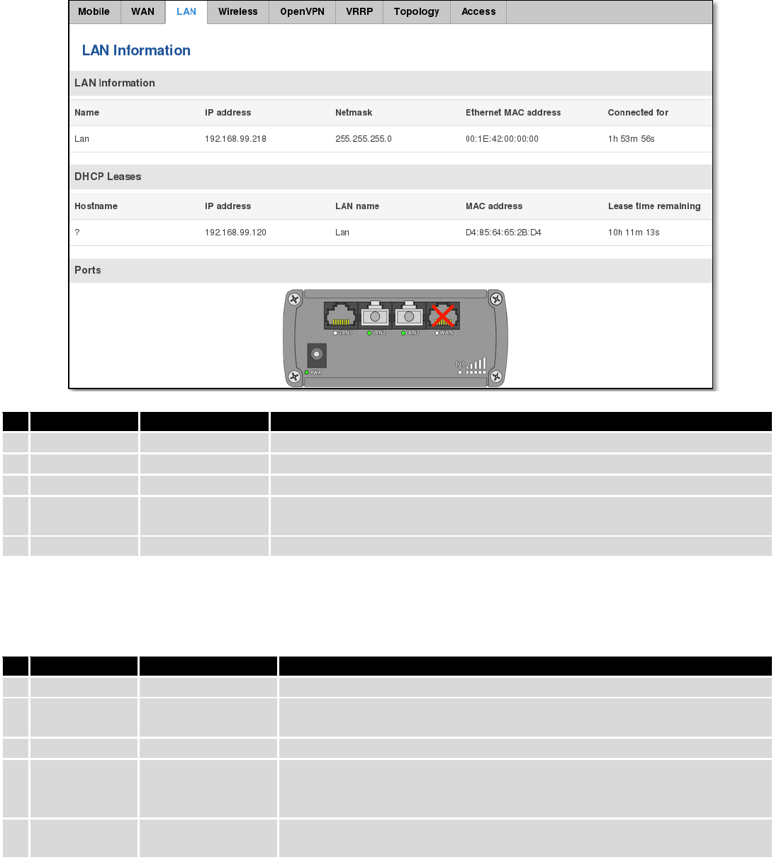
6.3.1.3 LAN
Display information about LAN connections.
24
LAN information:
Field Name
Sample Value
Explanation
1.
Name
Lan
Lan instance name
2.
IP address
192.168.99.218
Address that the router uses on the LAN network.
3.
Netmask
255.255.255.0
A mask used to define how large the LAN network is
4.
Ethernet LAN
MAC address
00:1E:42:00:00:00
MAC (Media Access Control) address used for communication in a Ethernet
LAN (Local Area Network)
5.
Connected for
1h 53m 56s
How long LAN has been successfully maintained.
DHCP Leases
If you have enabled a DHCP server this field will show how many devices have received an IP address and what
those IP addresses are.
Field Name
Sample Value
Explanation
1.
Hostname
?
DHCP client's hostname
2.
IP address
192.168.99.120
Each lease declaration includes a single IP address that has been leased to
the client
3.
Lan name
Lan
Lan instance name
4.
MAC address
D4:85:64:65:2B:D4
The MAC (Media Access Control) address of the network interface on
which the lease will be used. MAC is specified as a series of hexadecimal
octets separated by colons
5.
Lease time
remaining
10h 11m 13s
Remaining lease time for addresses handed out to clients
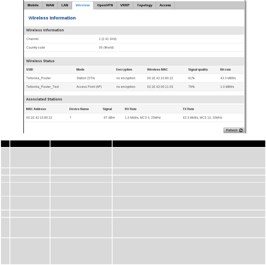
6.3.1.4 Wireless
Wireless can work in two modes, Access Point (AP) or Station (STA). AP is when the wireless radio is used to
create an Access Point that other devices can connect to. STA is when the radio is used to connect to an Access Point via
WAN.
25
6.3.1.4.1 Station
Display information about wireless connection (Station mode).
Client mode information
Field Name
Sample Value
Explanation
1.
Channel
1 (2.41 GHz)
The channel that the AP, to which the routers is connected to, uses.
Your wireless radio is forced to work in this channel in order to
maintain the connection.
2.
Country
00
Country code.
3.
SSID
Teltonika_Router
The SSID that the AP, to which the routers is connected to, uses.
4.
Mode
Station (STA)
Connection mode – Client indicates that the router is a client to
some local AP.
5.
Encryption
WPA2 PSK (CCMP)
The AP, to which the router is connected to, dictates the type of
encryption.
6.
Wireless MAC
00:1E:42:10:80:22
The MAC address of the access points radio.
7.
Signal Quality
61%
The quality between routers radio and some other device that is
connecting to the router. Will show 0% if no devices are trying to
connect or are currently maintaining a connection.
8.
Bit rate
43.3 MBit/s
The physical maximum possible throughput that the routers radio
can handle. Keep in mind that this value is cumulative - The bitrate
will be shared between the router and other possible devices that
connectto the local AP.
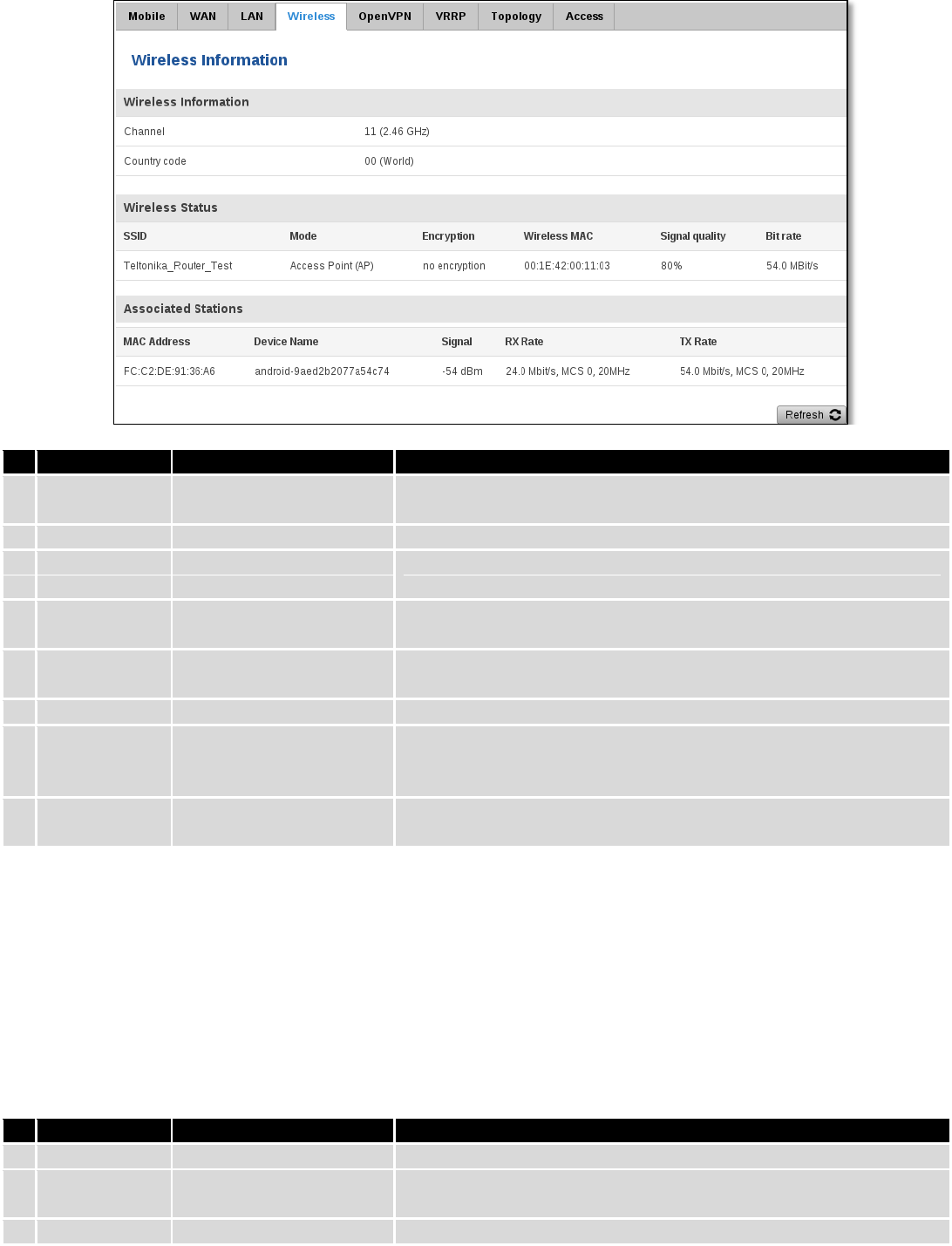
6.3.1.4.2 Access Point
Displays information about wireless connection (Access Point mode).
26
Wireless AP information
Field Name
Sample Value
Explanation
1.
Channel
11 (2.46 GHz)
The channel which is used to broadcast the SSID and to establish
new connections to devices.
2.
Country code
00(World)
Country code.
3.
SSID
Teltonika_Router_Test
The SSID that is being broadcast. Other devices will see this and will
be able to use to connect to your wireless network.
4.
Mode
Access Point (AP)
Connection mode – Master indicates that you router is an access
point.
5.
Encryption
No Encryption
The type of encryption that the router will use to authenticate,
establish and maintain a connection.
6.
Wireless MAC
00:1E:42:00:00:03
MAC address of your wireless radio.
7.
Signal Quality
80%
The quality between routers radio and some other device that is
connecting to the router. Will show 0% if no devices are trying to
connect or are currently maintaining a connection.
8.
Bit rate
54.0 MBit/s
The bitrate will be shared between all devices that connect to the
routers wireless network.
Additional note: MBit/s indicates the bits not bytes. To get the throughput in bytes divide the bit value by 8, for
e.g. 54MBits/s would be 6.75MB/s (Mega Bytes per second).
6.3.1.5 Associated Stations
Outputs a list of all devices and their MAC addresses that are maintain a connection with your router right now.
This can either be the information of the Access Point that the router is connecting to in STA mode or a list of all
devices that are connecting to the router in AP mode:
Field Name
Sample Value
Explanation
1.
MAC Address
FC:C2:DE:91:36:A6
Associated station's MAC (Media Access Control) address
2.
Device Name
Android-
9aed2b2077a54c74
DHCP client's hostname
3.
Signal
-54dBm
Received Signal Strength Indicator (RSSI). Signal's strength measured
27
in dBm
4.
RX Rate
24.0Mbit/s, MCS 0,
20MHz
The rate at which packets are received from associated station
5.
TX Rate
54.0Mbit/s, MCS 0,
20MHz
The rate at which packets are sent to associated station
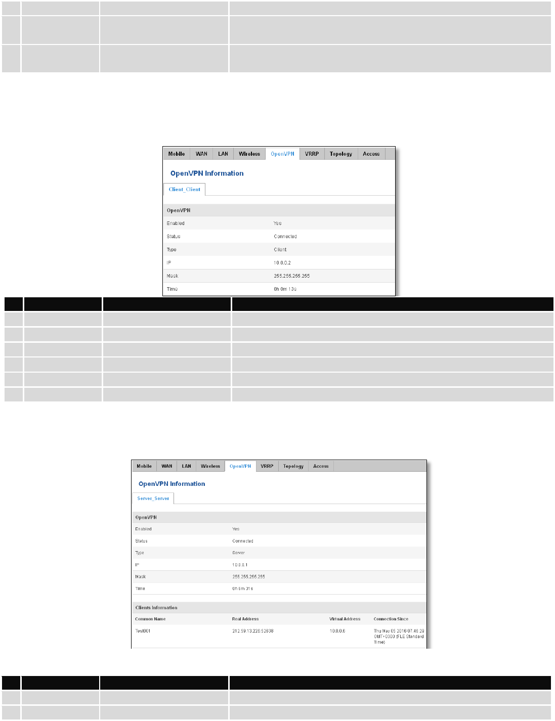
6.3.1.6 OpenVPN Client
Display OpenVPN connection information on client side.
Field Name
Sample Value
Explanation
1.
Enabled
Yes/No
OpenVPN status
2.
Status
Connected
Connection status
3.
Type
Client
A type of OpenVPN instance that has been created
4.
IP
10.0.0.2
Remote virtual network's IP address
5.
Mask
255.255.255.255
Remote virtual network's subnet mask
6.
Time
0h 0m 13s
For how long the connection has been established
6.3.1.7 OpenVPN Server
Display OpenVPN connection information on server side.
Field Name
Sample Value
Explanation
1.
Enabled
Yes/No
OpenVPN status
2.
Status
Connected
Connection status
28
2.
Type
Server
A type of OpenVPN instance that has been created
3.
IP
10.0.0.1
Remote virtual network's IP address
4.
Mask
255.255.255.255
Remote virtual network's subnet mask
5.
Time
0h 3m 24s
For how long the connection has been established
6.3.1.8 Clients information
It will show information, when router is configured as OpenVPN TLS server.
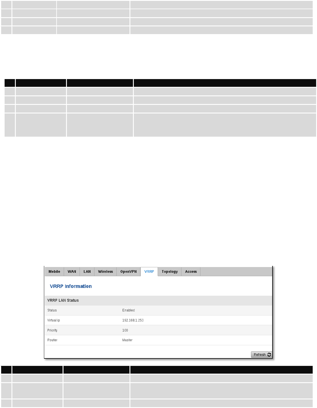
6.3.1.9 VRRP
VRRP (Virtual Router Redundancy Protocol) for LAN
Field Name
Sample Value
Explanation
1.
Status
Enabled
VRRP status
2.
Virtual IP
192.168.1.253
Virtual IP address(- es) for LAN’s VRRP (Virtual Router Redundancy
Protocol ) cluster
3.
Priority
100
Router with highest priority value on the same VRRP (Virtual Router
Field Name
Sample Value
Explanation
1.
Common Name
Test001
Client connection
2.
Real Address
212.59.13.225:52638
Client’s IP address and port number
3.
Virtual Address
10.0.0.6
Virtual address which has been given to a client
4.
Connection Since
Thu May 05 2016
07:46:29 GMT + 0300
(FLE Standard Time)
Since when connection has been established
29
Redundancy Protocol) cluster will act as a master, range [1 - 255]
4.
Router**
Master
Connection mode – Master
**-Exclusive to other Modes with Slave.
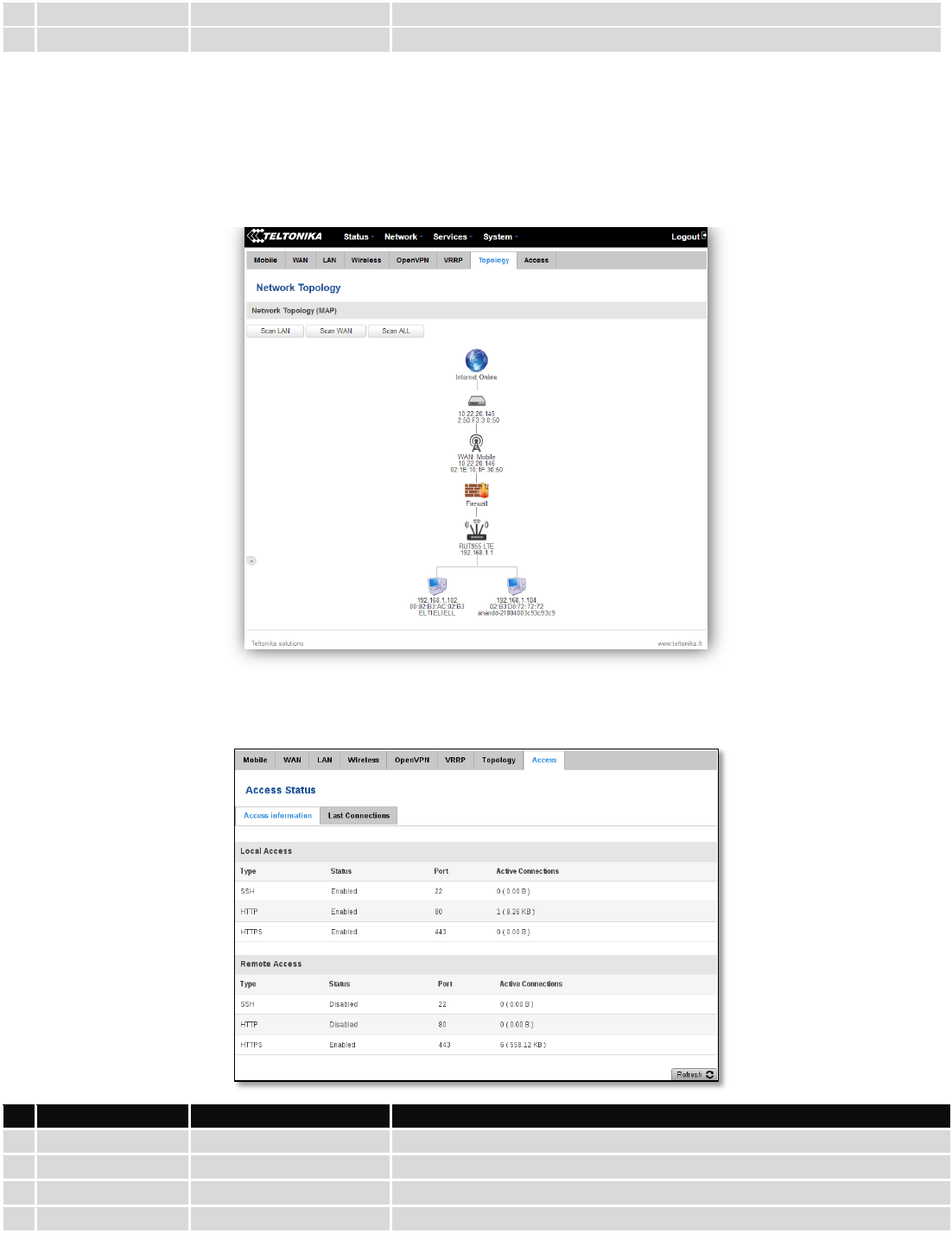
6.3.1.10 Topology
Network scanner allows you to quickly retrieve information about network devices. When router is configured to
use Mobile as WAN and Connection type is selected „PPP“, then possible to scan only the LAN side.
6.3.1.11 Access
Display information about local and remote active connections status.
Field Name
Sample Value
Explanation
1.
Type
SSH; HTTP; HTTPS
Type of connection protocol
2.
Status
Disabled/Enabled
Connection status
3.
Port
22; 80; 443
Connection port used
4.
Active
0(0.00B);1(9.26 KB);
Count of active connections and amount of data transmitted in KB
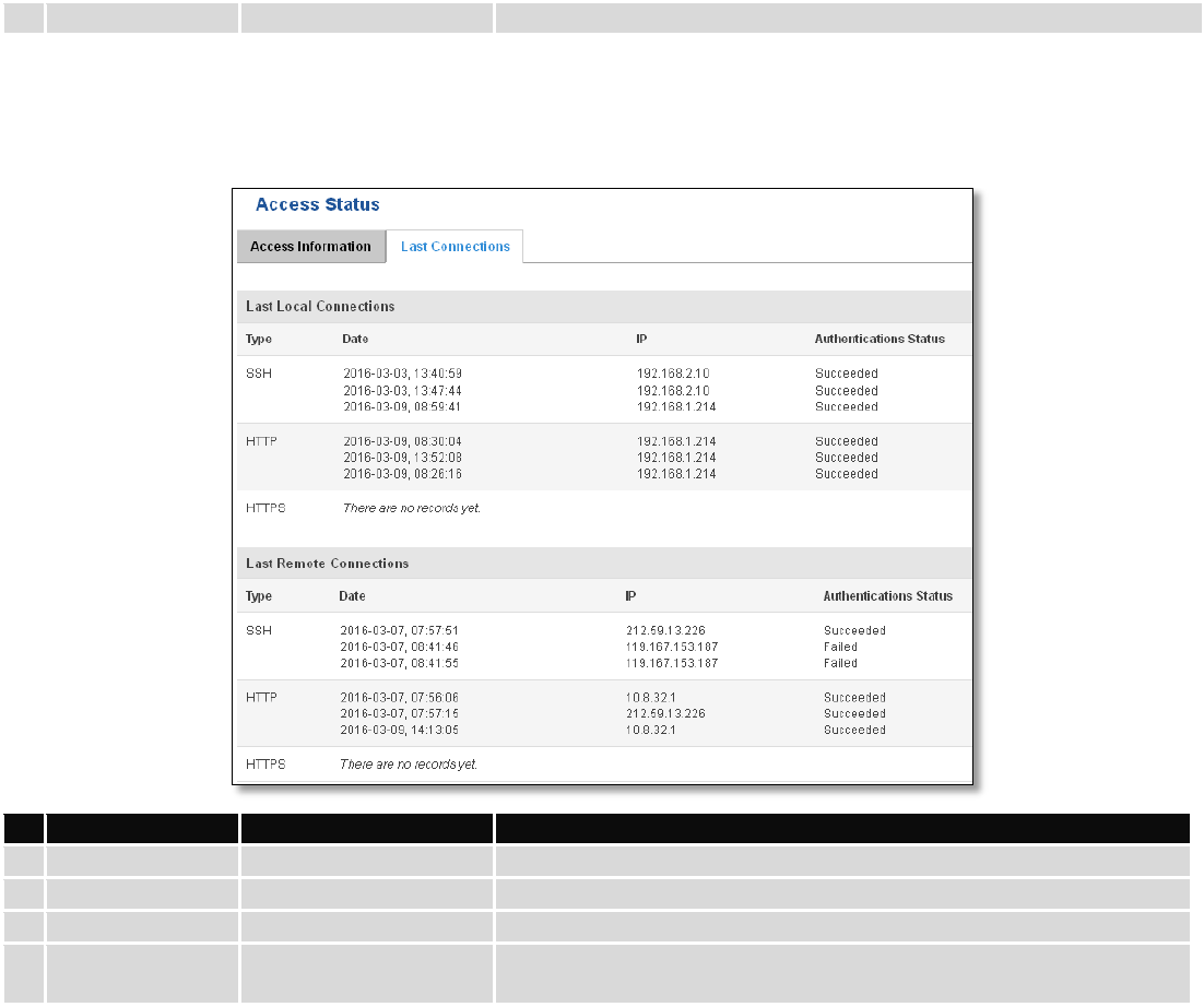
30
Connections
6(558.12 KB)
**-Exclusive to other Modes with Slave.
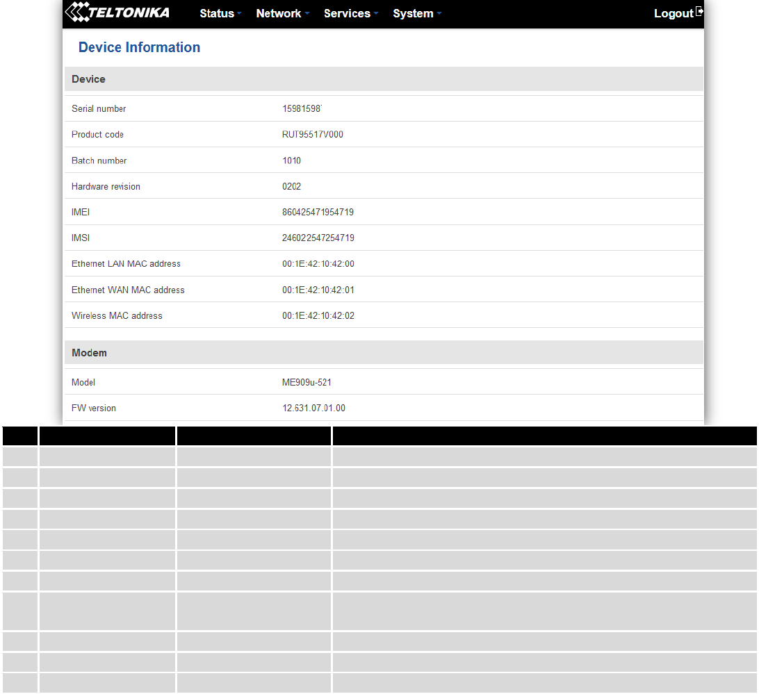
6.3.1.11.1 Last Connections
Displays information about local and remote last 3 connections status
Field Name
Sample Value
Explanation
1.
Type
SSH; HTTP; HTTPS
Type of connection protocol
2.
Date
2016-03-03, 13:40:59
Date and time of connection
3.
IP
192.168.2.10
IP address from which the connection was made
4.
Authentications
Status
Failed; Succeed
Status of authentication attempt
6.4 Device information
The page displays factory information that was written into the device during manufacturing process.
31
Field Name
Sample Value
Explanation
1.
Serial number
15981598
Serial number of the device
2.
Product code
RUT95517V000
Product code of the device
3.
Batch number
1010
Batch number used during device’s manufacturing process
4.
Hardware revision
0202
Hardware revision of the device
5.
IMEI
860425471954819
Identification number of the internal modem
6.
IMSI
246022547254719
Subscriber identification number of the internal modem
6.
Ethernet LAN MAC
00:1E:42:10:42:00
MAC address of the Ethernet LAN ports
7.
Ethernet WAN
MAC
00:1E:42:10:42:01
MAC address of the Ethernet WAN port
8.
Wireless MAC
00:1E:42:10:42:02
MAC address of the Wi-Fi interface
9.
Model
ME909-521
Router’s modem model
10.
FW version
12.631.07.01.00
Router’s modem firmware version
32
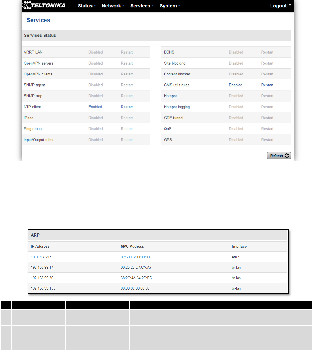
6.5 Services
The page displays usage of the available services.
1.1 Routes
The page displays ARP table and active IP routes of the device.
6.5.1 ARP
Show the routers active ARP table. An ARP table contains recently cached MAC addresses of every immediate
device that was communicating with the router.
Field Name
Sample Value
Explanation
1.
IP Address
192.168.99.17
Recently cashed IP addresses of every immediate device that was
communicating with the router
2.
MAC Address
00:25:22:D7:CA:A7
Recently cached MAC addresses of every immediate device that was
communicating with the router
3.
Interface
br-lan
Interface used for connection
33
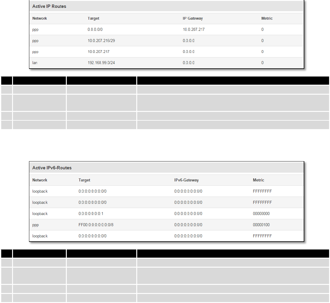
6.5.2 Active IP-Routes
Show the routers routing table. The routing table indicates where a TCP/IP packet, with a specific IP address,
should be directed to.
Field Name
Sample Value
Explanation
1.
Network
ppp
Interface to be used to transmit TCP/IP packets through
2.
Target
192.168.99.0/24
Indicates where a TCP/IP packet, with a specific IP address, should
be directed
3.
IP Gateway
0.0.0.0
Indicates through which gateway a TCP/IP packet should be directed
4.
Metric
0
Metric number indicating interface priority of usage
6.5.3 Active IPv6-Routes
Display active IPv6 routes for data packet transition.
Field Name
Sample Value
Explanation
1.
Network
loopback
Network interface used
2.
Target
0:0:0:0:0:0:0:0/0
Indicates where a TCP/IP packet, with a specific IP address, should
be directed
3.
IPv6-Gateway
0:0:0:0:0:0:0:0/0
Indicates through which gateway a TCP/IP packet should be directed
4.
Metric
FFFFFFFF
Metric number indicating interface priority of usage
6.6 Graphs
Real-time graphs show how various statistical data changes over time.
6.6.1 Mobile Signal Strength
Displays mobile signal strength variation in time (measured in dBm)
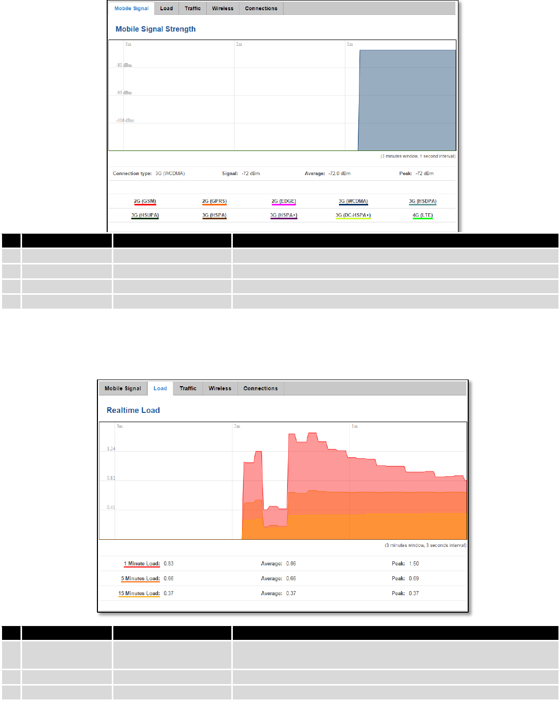
34
Field Name
Sample Value
Explanation
1.
Connection type
3G (WCDMA)
Type of mobile connection used
2.
Signal
-72 dBm
Current signal strength value
3.
Average
-72.0 dBm
Average signal strength value
4.
Peak
-72 dBm
Peak signal strength value
6.6.2 Realtime Load
This tri-graph illustrates average CPU load values in real time. The graph consists out of three color coded graphs,
each one corresponding to the average CPU load over 1 (red), 5 (orange) and 15 (yellow) most recent minutes.
Field Name
Sample Value
Explanation
1.
1/5/15 Minutes
Load
0.83
Time interval for load averaging, colour of the diagram
2.
Average
0.86
Average CPU load value over time interval (1/5/15 Minute)
3.
Peak
1.50
Peak CPU load value of the time interval
35
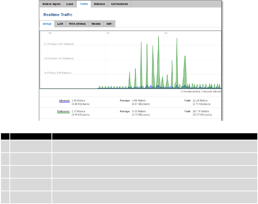
6.6.3 Realtime Traffic
This graph illustrates average system inbound and outbound traffic over the course of ~3 minutes; each new
measurement is taken every 3 seconds. The graph consists out of two colors coded graphs (green graph shows the
outbound traffic, blue graph shows inbound traffic). Although not graphed, the page also displays peak loads and
average of inbound and outbound traffic.
Field Name
Explanation
1.
Bridge
Cumulative graph, which encompasses wired Ethernet LAN and the wireless network.
2.
LAN
Graphs the total traffic that passes through both LAN network interfaces.
3.
WAN (Wired)
Graphs the amount of traffic which passed through the current active WAN connection.
4.
Mobile
Graphs the amount of traffic which passed through the mobile network connection.
5.
Wi-Fi
Shows the amount of traffic that has been sent and received through the wireless radio.
36
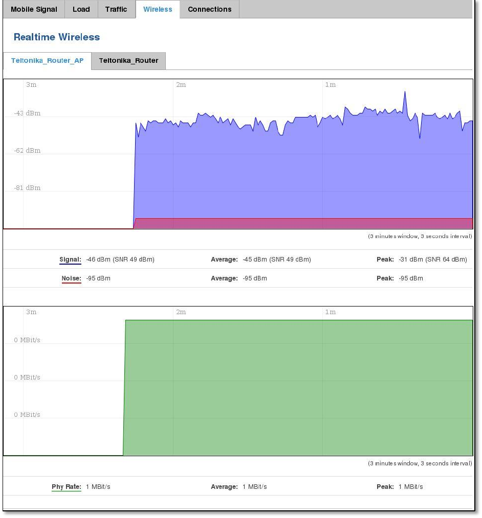
6.6.4 Realtime Wireless
Display the wireless radio signal, signal noise and theoretical maximum channel permeability. Average and peak
signal levels are displayed.
37
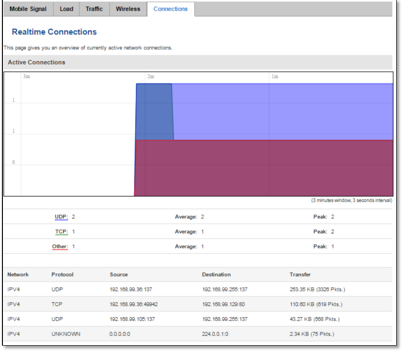
6.6.5 Realtime Connections
Displays currently active network connections with the information about network, protocol, source and
destination addresses, transfer speed.
38
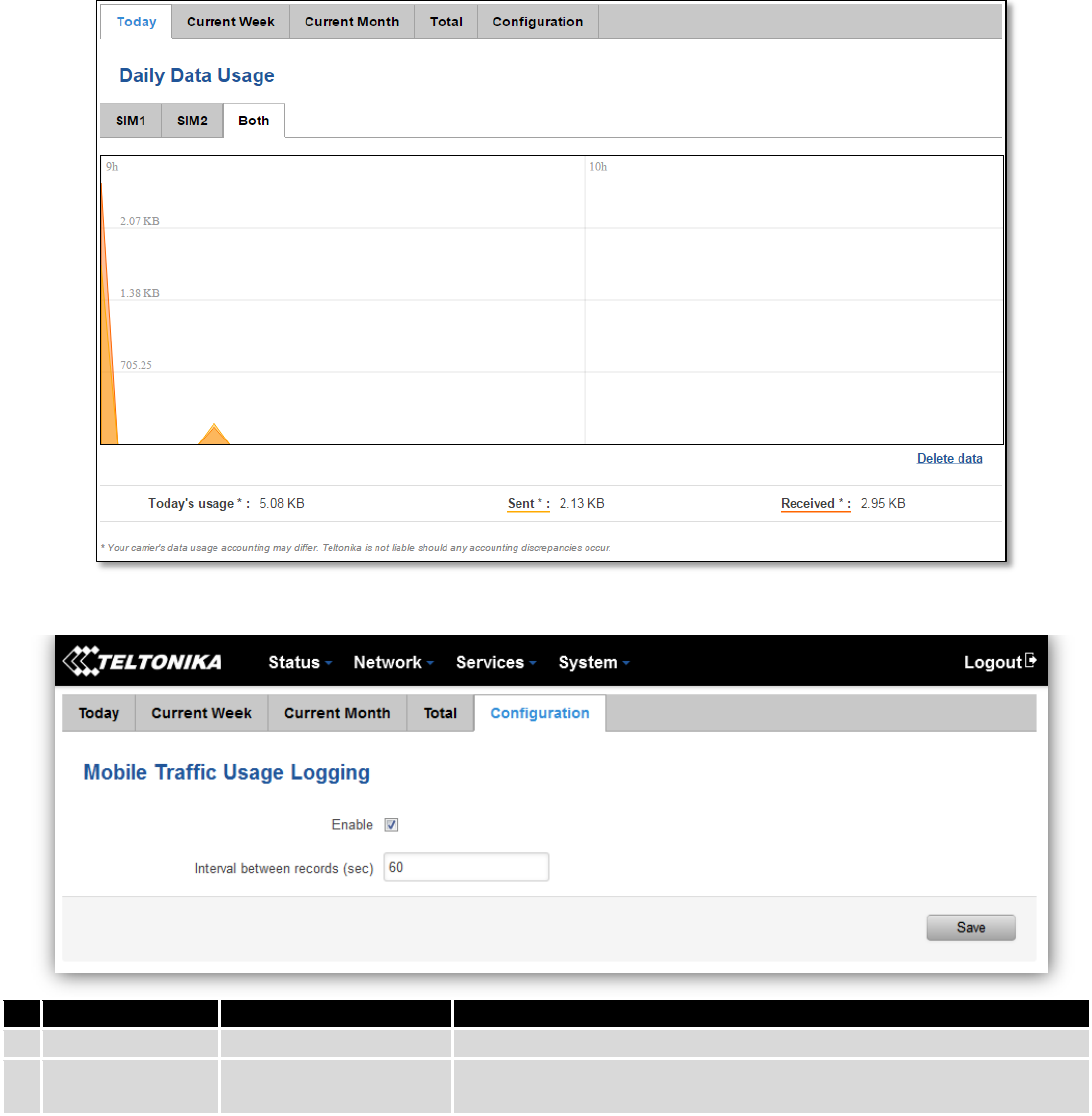
6.7 Mobile Traffic
Displays mobile connection data sent and received in KB of this day, week, Month.
By default mobile traffic usage logging is disabled. To use this functionality is needed to enable it.
Field Name
Sample Value
Explanation
1.
Enable
Enable/Disable
Make a functionality active/inactive
2.
Interval between
records (sec)
60
The interval between logging records (minimum 60 sec)
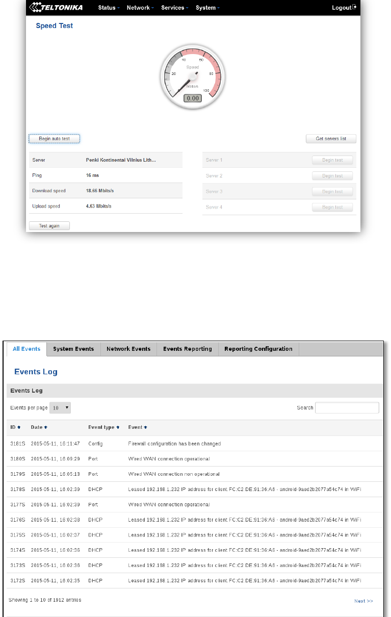
6.8 Speed Test
Speed test is a tool for measuring your internet connection upload and download speeds. You can select servers
for manual testing, or use auto test.
39
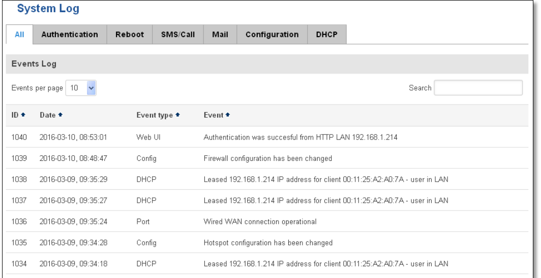
6.9 Events Log
Event log displays such actions as: login, reboot, firmware flashing and reset.
6.9.1 All Events
Display all router events, their types and time of occurrence.
40
6.9.2 System Events
Display all system events, their type and time of occurrence. Events include authentication or reboot requests,
incoming and outgoing SMS and calls, Mails, Configuration changes, DHCP events.
41
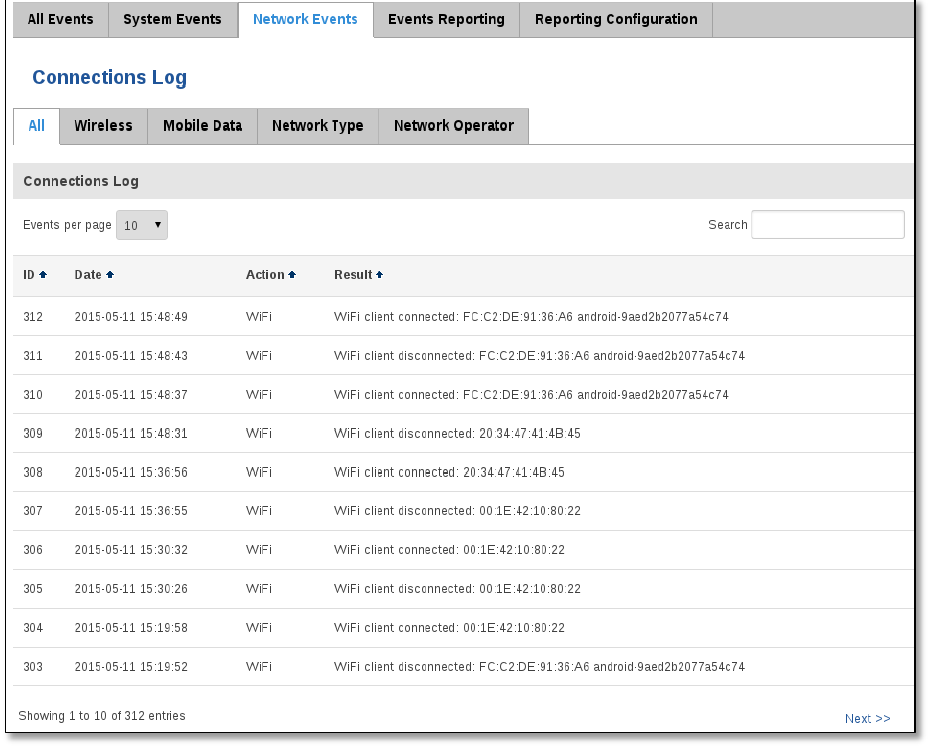
6.9.3 Network Events
Display information about recent network events like connection status change, lease status change, network
type or operator change.
42
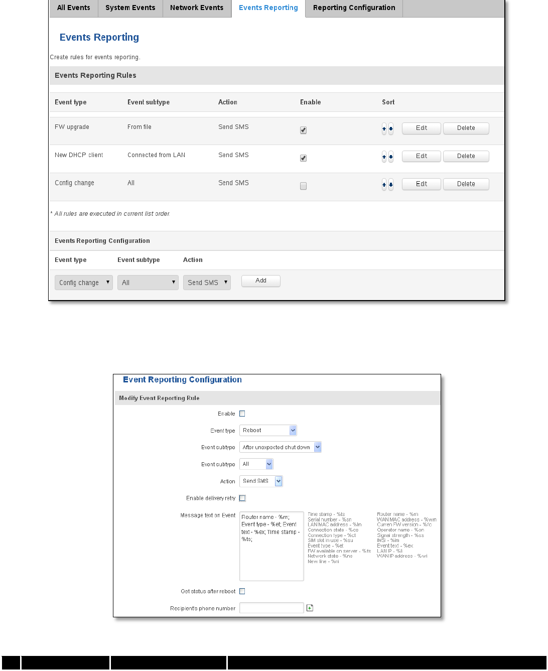
6.9.4 Events Reporting
Allow to view, enable/disable or modify created rules for events reporting.
6.9.4.1 Events Reporting Configuration
Allow to review created rules details and modify them, so after event occurrence, messages or emails are sent to
specified address or phone numbers with information about the event.
Field Name
Sample Value
Explanation
43
1.
Enable
Enable/Disable
Make a rule active/inactive
2.
Event type
Reboot
Select event type about which occurrence information will be sent
3.
Event subtype
After unexpected shut
down
Specify event subtype to activate the rule
4.
Event subtype
All/Loaded
Event subtype for which the rule is applied
5.
Action
Send SMS
Action to perform when an event occurs
6.
Enable delivery
retry
Enable/Disable
Enables to send SMS again if first try to send SMS was unsuccessful.
7.
Message text on
Event
Router name - %rn;
Event type - %et; Event
text - %ex; Time stamp
- %ts;
Message text on specific event
8
Get status after
reboot
Enable/Disable
Receive router status information after reboot
9.
Recipient‘s
phone number
+123456789
For whom you want to send a SMS
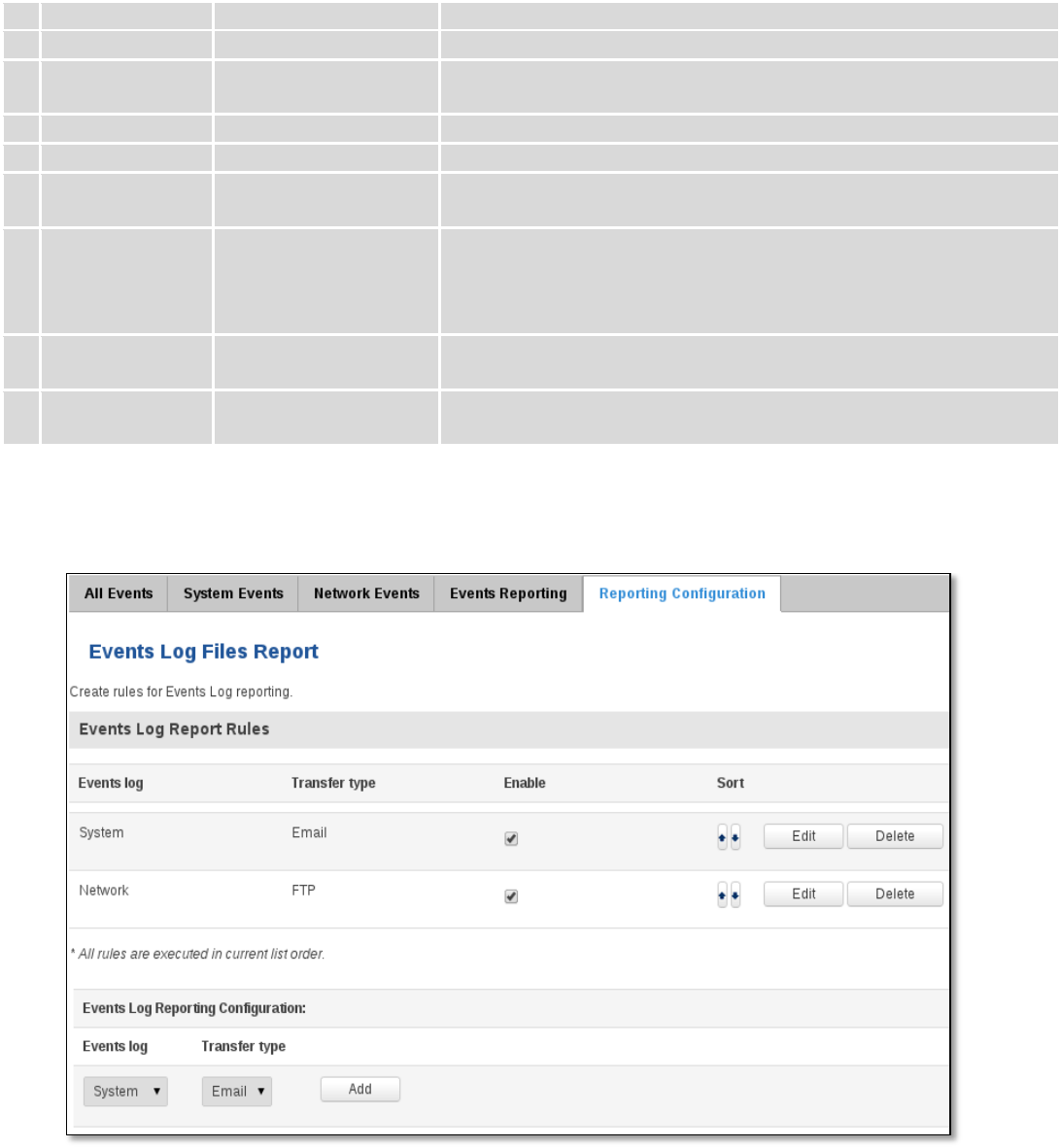
6.9.5 Reporting Configuration
Displays configured services for event reporting, allows enabling, disabling, viewing and modifying parameters.
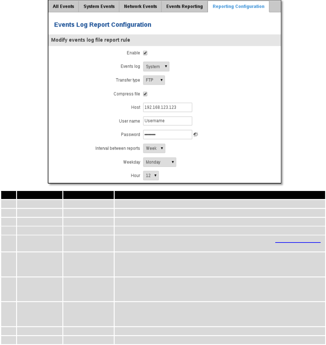
6.9.5.1 Events Log Report Configuration
Allow to change the configuration of periodic events reporting to email or FTP.
44
FTP:
Field Name
Sample Value
Explanation
1.
Enable
Enable/Disable
Make a rule active/inactive
2.
Events log
System
Events log for which the rule is applied
3.
Transfer type
FTP
Events log file transfer type: Email/FTP
4.
Compress file
Enable
Enable/disable compress events log file using gzip
5.
Host
192.168.123.123
FTP (File Transfer Protocol) host name, e.g. ftp.exemple.com,
192.168.123.123. Allowed characters (a-z-A-Z0-9!@#$%^&*+-/=?_`{|}~. )
6.
User name
Username
User name for authentication on SMTP (Simple Mail Transfer Protocol) or
FTP (File Transfer Protocol) server. Allowed characters (a-z-A-Z0-
9!@#$%^&*+-/=?_`{|}~. )
7.
Password
password
Password for authentication on SMTP (Simple Mail Transfer Protocol) or FTP
(File Transfer Protocol) server. Allowed characters (a-z-A-Z0-9!@#$%^&*+-
/=?_`{|}~. )
8.
Interval
between
reports
Week
Send report every selected time interval
9.
Weekday
Monday
Day of the week to get events log report
10.
Hour
12
Hour of the day to get events log report
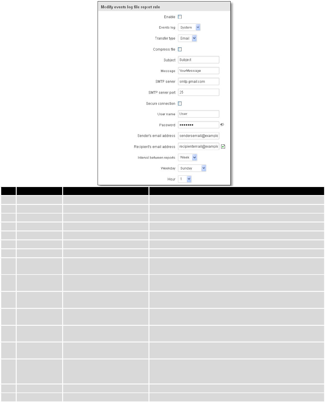
Email:
45
Field Name
Sample Value
Explanation
1.
Enable
Enable/Disable
Make a rule active/inactive
2.
Events log
System
Event log for which the rule is applied
3.
Transfer type
Email
Events log file transfer type: Email/FTP
4.
Compress file
Enable
Enable/disable compress events log file using gzip
5.
Subject
Subject
Subject of an email
6.
Message
YourMessage
Message to send in email
7.
SMTP server
smtp.gmail.com
SMTP (Simple Mail Transfer Protocol) server address
8.
SMTP server
port
25
SMTP (Simple Mail Transfer Protocol) server port
9.
Secure
connection
Enable/Disable
Enables/disables secure connection. Use only if server supports
SSL or TLS
10.
User name
User
User name for authentication on SMTP (Simple Mail Transfer
Protocol)
11.
Password
●●●●●●●
User password for authentication on SMTP (Simple Mail
Transfer Protocol)
12.
Sender‘s email
address
sendersemail@example.com
An address that will be used to send your email from. Allowed
characters (a-zA-Z0-9._%+-)
13.
Recipient‘s
email address
recipientemail@example.com
For whom you want to send an email to. Allowed characters (a-
zA-Z0-9._%+-)
14.
Interval
between
reboots
Week
Send report every select time interval
15.
Weekday
Sunday
Day of the week to get events log report
16.
Hour
1
Hour of the day to get events log report
46
7 Network
7.1 Mobile
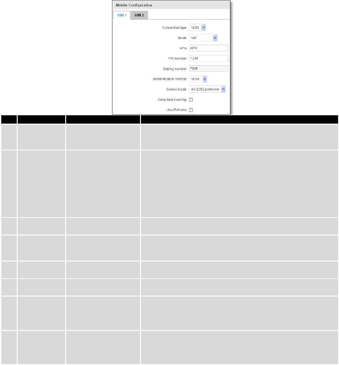
7.1.1 General
7.1.1.1 Mobile configuration
Here you can configure mobile settings which are used when connecting to your local 3G/LTE network.
Field Name
Sample value
Explanation
1.
Connection
type
PPP / NDIS
PPP mode uses dialling number to establish data connection.
NDIS mode (default) does not use dialling and PPP protocol to
establish data connection it is usually faster than PPP mode.
2.
Mode
NAT / Passthrough / Use
bridge
NAT mode enables network address translation on router. Bridge
mode bridges LTE data connection with LAN. In this mode the router
does not have internet connection as ISP provides IP directly to end
device (PC, tablet or smart phone).Using Bridge mode will disable
most of the router capabilities and you can access your router's
settings only by using static IP address on your end device.
Passthrough mode is similar with bridge mode except that in
passthrough mode router does have internet connection.
3.
APN
“APN”
Access Point Name (APN) is a configurable network identifier used
by a mobile device when connecting to a GSM carrier.
4.
PIN number
“1234” or any number
that falls between 0000
and 9999
A personal identification number is a secret numeric password
shared between a user and a system that can be used to
authenticate the user to the system.
5.
Dialing
number
*99***1#
Dialling number is used to establish a mobile PPP (Point-to-Point-
Protocol) connection.
6.
Authentication
method
CHAP, PAP or none
Authentication method, which your carrier uses to authenticate new
connections. (This selection is unavailable on the alternate model)
7.
Username
“username”
Your username that you would use to connect to your carriers
network. This field becomes available when you select an
authentication method (i.e. authentication method is not “none”).
These fields are always enabled on the alternate model.
8.
Password
“password”
Your password that you would use to connect to your carriers
network. This field becomes available when you select an
authentication method (i.e. authentication method is not “none”).
These fields are always enabled on the alternate model.
47
9.
Service mode
2G only, 2G preferred,
3G only, 3G preferred,
4G (LTE) only, 4G (LTE)
preferred or automatic.
Your network preference. If your local mobile network supports 2G,
3G and 4G (LTE) you can specify to which network you wish to
connect. E.g.: if you choose 2G, the router will connect to a 2G
network, so long as it is available, otherwise it will connect to a
network that provides better connectivity. If you select auto, then
the router will connect to the network that provides better
connectivity.
10.
Deny data
roaming
Enable/Disable
If enabled this function prevents the device from establishing mobile
data connection while not in home network.
11.
Use IPv4 only
Enable / Disable
If enabled this function makes the device to use only IPv4 settings
when connecting to operator.
Warning: If an invalid PIN number was entered (i.e. the entered PIN does not match the one that was used to
protect the SIM card), your SIM card will get blocked. To avoid such mishaps it is highly advised to use an unprotected
SIM. If you happen to insert a protected SIM and the PIN number is incorrect, your card won’t get blocked immediately,
although after a couple of reboots OR configuration saves it will.
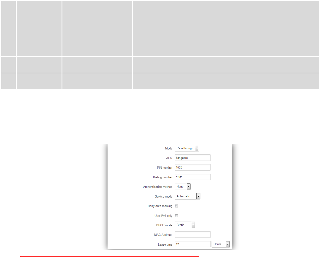
7.1.1.1.1 Passthrough mode
Using Passthrough Mode will disable most of the router capabilities!
DHCP mode: Static
Enter your computer MAC address (xx:xx:xx:xx:xx:xx) to MAC Address field and select Lease time (expire time for
lease addresses). Device, which MAC address will be entered, will get IP from GSM operator. Other connected devices to
the router LAN will get IP from router DHCP server, but these devices will not have internet access.
DHCP mode: Dynamic
Using Dynamic mode, device will get IP from GSM operator , which connect to the router firstly. Using
Passthrough in dynamic mode, the DHCP in LAN will be disabled.
DHCP mode: No DHCP
Using no DHCP mode, IP (also subnet, gateway and DNS) from GSM operator should be entered in device, which is
connected to the router LAN, manually. Using Passthrough in no DHCP mode, the DHCP in LAN will be disabled.
48
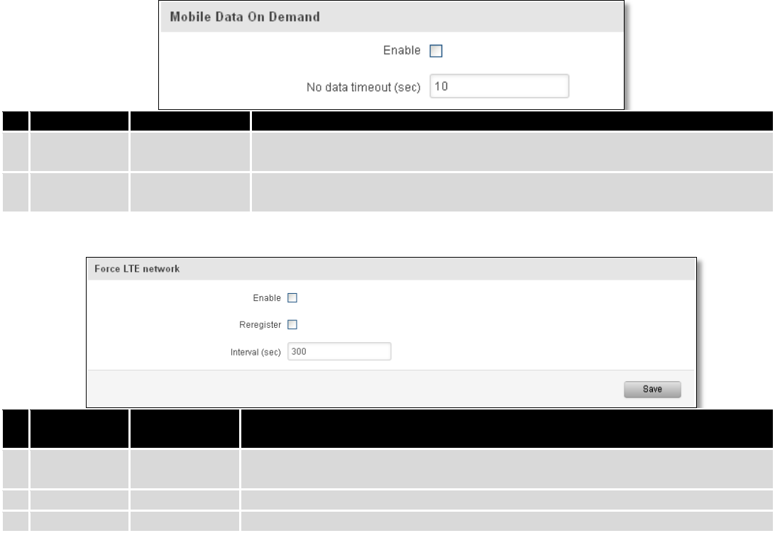
7.1.1.2 Mobile Data On Demand
Field name
Possible values
Explanation
1.
Enable
Enable/Disable
Mobile Data On Demand function enables you to keep mobile data connection
on only when it's in use
2.
No data
timeout(sec)
1-99999999
A mobile data connection will be terminated if no data is transferred during the
timeout period
7.1.1.3 Force LTE network
Field name
Possible
values
Explanation
1.
Enable
Enable/Disable
Enable/disable try to connect to LTE network every x seconds (used only if
service mode is set to 4G (LTE) preferred)
2.
Reregister
Enable/Disable
If this enabled, modem will be reregister before try to connect to LTE network
3.
Interval (sec)
180 - 3600
Time in seconds between tries to connect to LTE network. Range [180-3600]
49
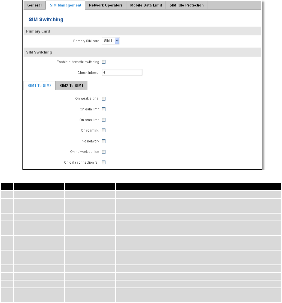
7.1.2 SIM Management
Field name
Possible values
Explanation
1.
Primary SIM card
SIM 1 / SIM 2
SIM card that will be used in the system as a primary SIM card
2.
Enable automatic
switching
Enable/Disable
Automatically switch between primary and secondary SIM cards
based on the various rules and criterions defined below
3.
Check interval
1-3600
Check interval in seconds
4.
On weak signal
Enable/Disable
Perform a SIM card switch when a signal's strength drops below a
certain threshold
5.
On data limit*
Enable/Disable
Perform a SIM card switch when mobile data limit for your current
SIM card is exceeded
6.
On SMS limit*
Enable/Disable
Perform a SIM card switch when SMS limit for your current SIM card
is exceeded
7.
On roaming
Enable/Disable
Perform a SIM card switch when roaming is detected
8.
No network
Enable/Disable
Perform a SIM card switch when no operator is detected
9.
On network denied
Enable/Disable
Perform a SIM card switch when network is denied
10.
On data connection
fail
Enable/Disable
Perform a SIM card switch when data connection fails
* Your carrier's data usage accounting may differ. Teltonika is not liable should any accounting discrepancies occur.
50
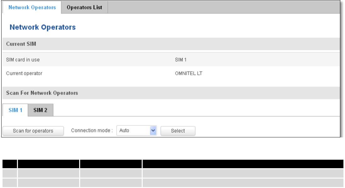
7.1.3 Network Operators
7.1.3.1 Network Operators
This function lets you Scan, Select and enter manual Network Operator to which router should connect. Function
will provide great utility when router is in Roaming conditions. Operator is selected only for the active SIM card. In order
to specify operator for the other SIM card it must first be selected as primary SIM in “SIM Management”.
Note: after clicking Scan for operators’ button- You will lose current mobile connection! For changing network operator
status have to be available. There is manual connection to network operator, you have to fill numeric name, and it’s
have to be available.
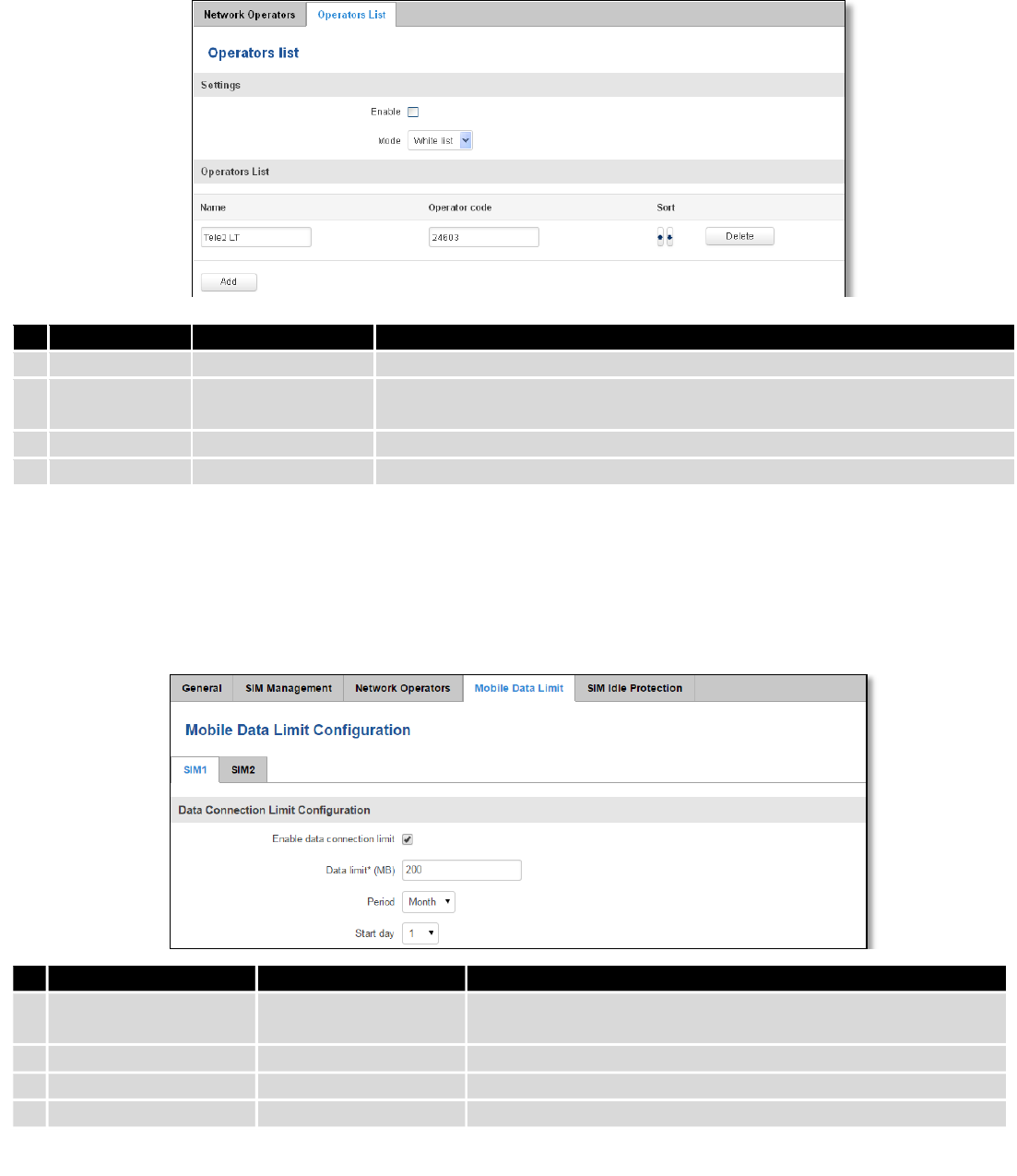
7.1.3.2 Operator List
This function lets to create white list/black list based on operator’s code.
Field Name
Sample Value
Explanation
1.
SIM card in use
SIM 1 / SIM 2
Shows current SIM card’s in use
2.
Current operator
OMNITEL LT
Operator's name of the connected GSM network
51
Field name
Possible values
Explanation
1.
Enable
Enable/Disable
Enable/disable operators blocking
2.
Mode
White list/Black list
White list - allows every operator on the list and blocks everything else.
Black list – block every operator on the list and allow everything else
3.
Name
Tele2 LT
Operator’s name
4.
Operator code
24603
Operator’s code
7.1.4 Mobile Data Limit
This function lets you limit maximum amount of data transferred on WAN interface in order to minimize
unwanted traffic costs.
7.1.4.1 Data Connection Limit Configuration
* Your carrier's data usage accounting may differ. Teltonika is not liable should any accounting discrepancies occur.
Field Name
Sample value
Explanation
1.
Enable data
connection limit
Enable/Disable
Disables mobile data when a limit for current period is reached
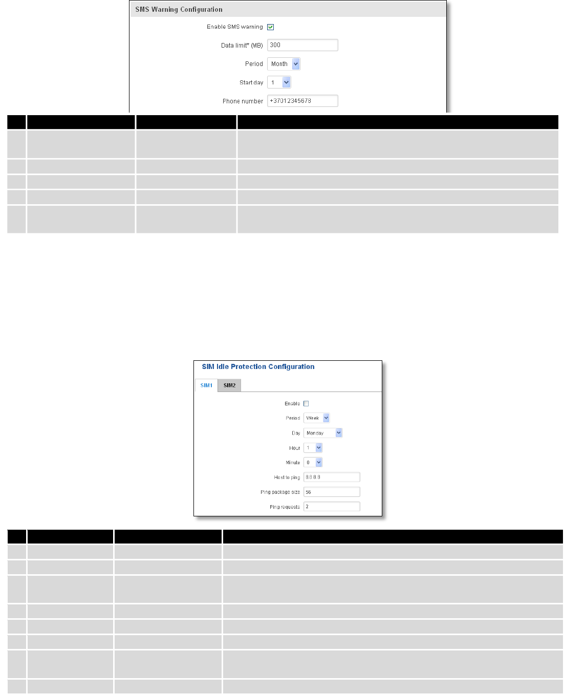
2.
Data limit* (MB)
200
Disable mobile data after limit value in MB is reached
3.
Period
Month/Week/Day
Period for which mobile data limiting should apply
4.
Start day/ Start hour
1
A starting time for mobile data limiting period
52
7.1.4.2 SMS Warning Configuration
* Your carrier's data usage accounting may differ. Teltonika is not liable should any accounting discrepancies occur.
7.1.5 SIM Idle protection
Some operators block user SIM cards after period of inactivity. This function enables router to periodically switch
to secondary SIM card and establish data connection with mobile network in order to prevent SIM card blocking.
7.1.5.1 Settings
Field Name
Sample value
Explanation
1.
Enable
Enable/Disable
Enables SIM idle protection
2.
Period
Month / Week
Switches between monthly and weekly SIM activation periods
3.
Day
1-31 / Monday -
Sunday
Specifies the day for SIM idle protection activation, 1-31 if Period is
Month, and Monday – Sunday if period is week.
4.
Hour
1-24
Specifies the hour for SIM idle protection activation
5.
Minute
1-60
Specifies the minute for SIM idle protection activation
6.
Host to ping
8.8.8.8
Specifies IP address or domain name to send data packages to
7.
Ping package
size
56
Specifies ping Package size in bytes
8.
Ping requests
2
Specifies requests to be sent
Field Name
Sample value
Explanation
1.
Enable SMS warning
Enable/Disable
Enables sending of warning SMS message when mobile data limit for
current period is reached
2.
Data limit* (MB)
300
Send warning SMS message after limit value in MB is reached
3.
Period
Month/Week/Day
Period for which mobile data limiting should apply
4.
Start day/ Start hour
1
A starting time for mobile data limiting period
5.
Phone number
+37012345678
A phone number to send warning SMS message to, e.g.
+37012345678
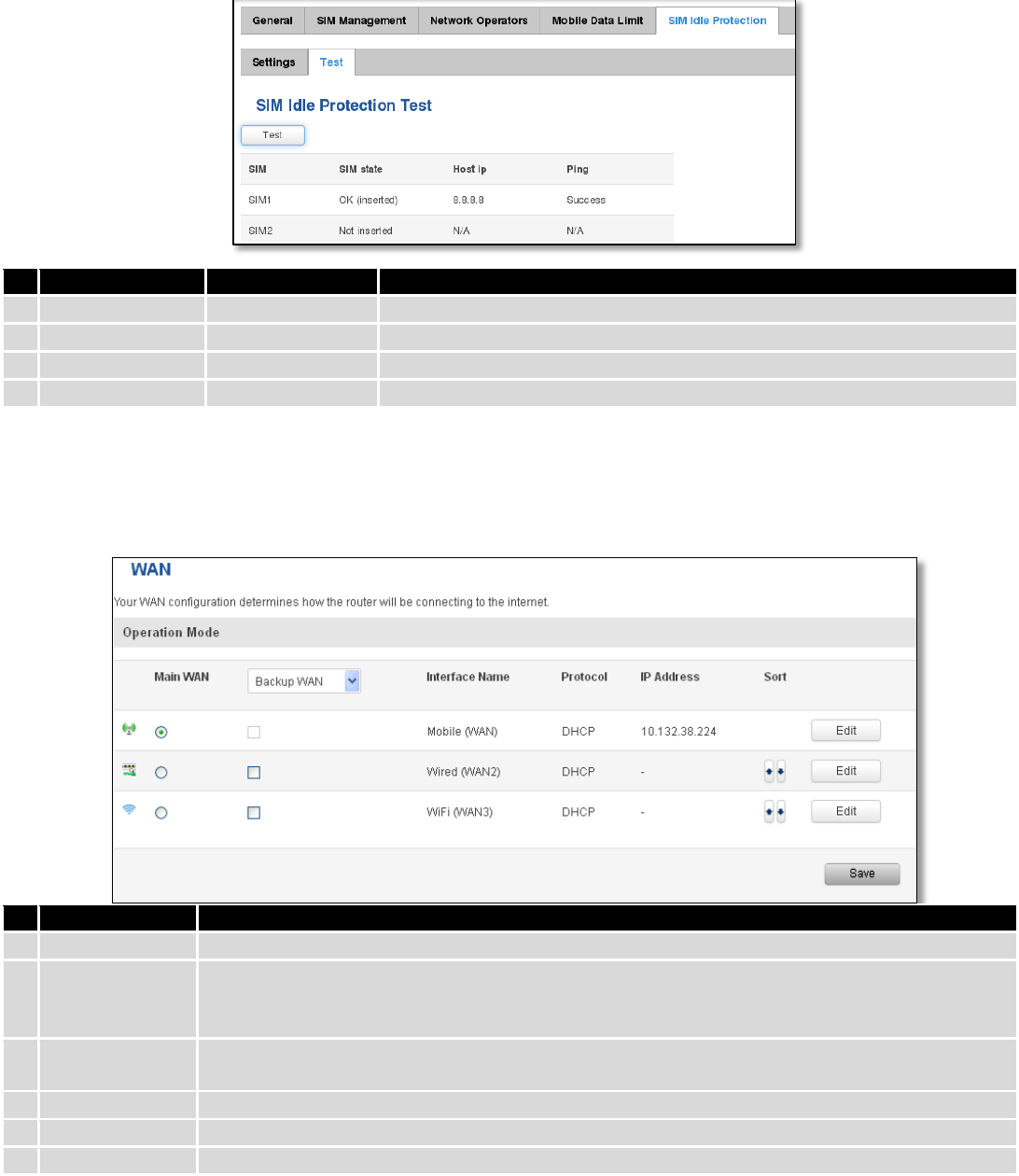
53
7.1.5.2 Test
Tests the functioning of idle protection with your parameters entered at settings tab.
Field Name
Sample value
Explanation
1.
SIM
SIM1 / SIM2
Displays SIM number
2.
SIM state
OK (inserted)
Displays status of the SIM card
3.
Host IP
8.8.8.8
Displays the IP of the Host
4.
Ping
Success
Displays status of ping attempt
7.2 WAN
7.2.1 Operation Mode
Your WAN configuration determines how the router will be connecting to the internet.
Type
Explanation
1.
Main WAN
Switches between Mobile, Wired and Wi-Fi interface for main WAN
2.
Backup
WAN/Load
balancing
Let’s user to select one or two interfaces for WAN backup
3.
Interface Name
Displays WAN interface name, and changes interface priority, the interface at the table top has
the highest priority
4.
Protocol
Displays protocol used by WAN interface
5.
IP Address
Displays IP address acquired by specific interface
6.
Sort
Sorts table rows and changes interface priority, the highest interface has highest priority
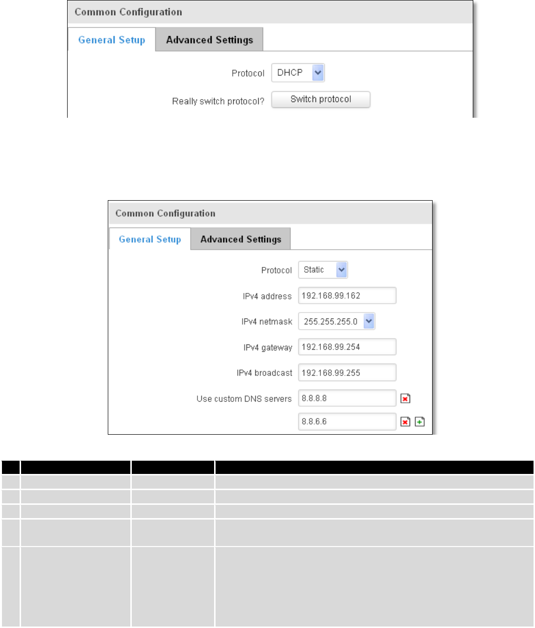
54
7.2.2 Common configuration
Common configuration allows you to configure your TCP/IP settings for the wan network.
You can switch between the Static, DHCP or PPPoE protocol by selecting the protocol that you want to use and
then pressing Switch Protocol.
7.2.2.1 General Setup
7.2.2.1.1 Static:
This is the configuration setup for when you select the static protocol.
Filed name
Sample
Explanation
1.
IPv4 address
192.168.99.162
Your routers address on the WAN network
2.
IPv4 netmask
255.255.255.0
A mask used to define how “large” the WAN network is
3.
IPv4 gateway
192.168.99.254
Address where the router will send all the outgoing traffic
4.
IPv4 broadcast
192.168.99.255
Broadcast address (auto generated if not set). It is best to leave this
blank unless you know what you are doing.
5.
Use custom DNS
servers
8.8.8.8
8.8.6.6
Usually the gateway has some predefined DNS servers. As such the
router, when it needs to resolve a hostname (“www.google.com”,
“www.cnn.com”, etc…) to an IP address, it will forward all the DNS
requests to the gateway. By entering custom DNS servers the router
will take care of host name resolution. You can enter multiple DNS
servers to provide redundancy in case the one of the server fails.
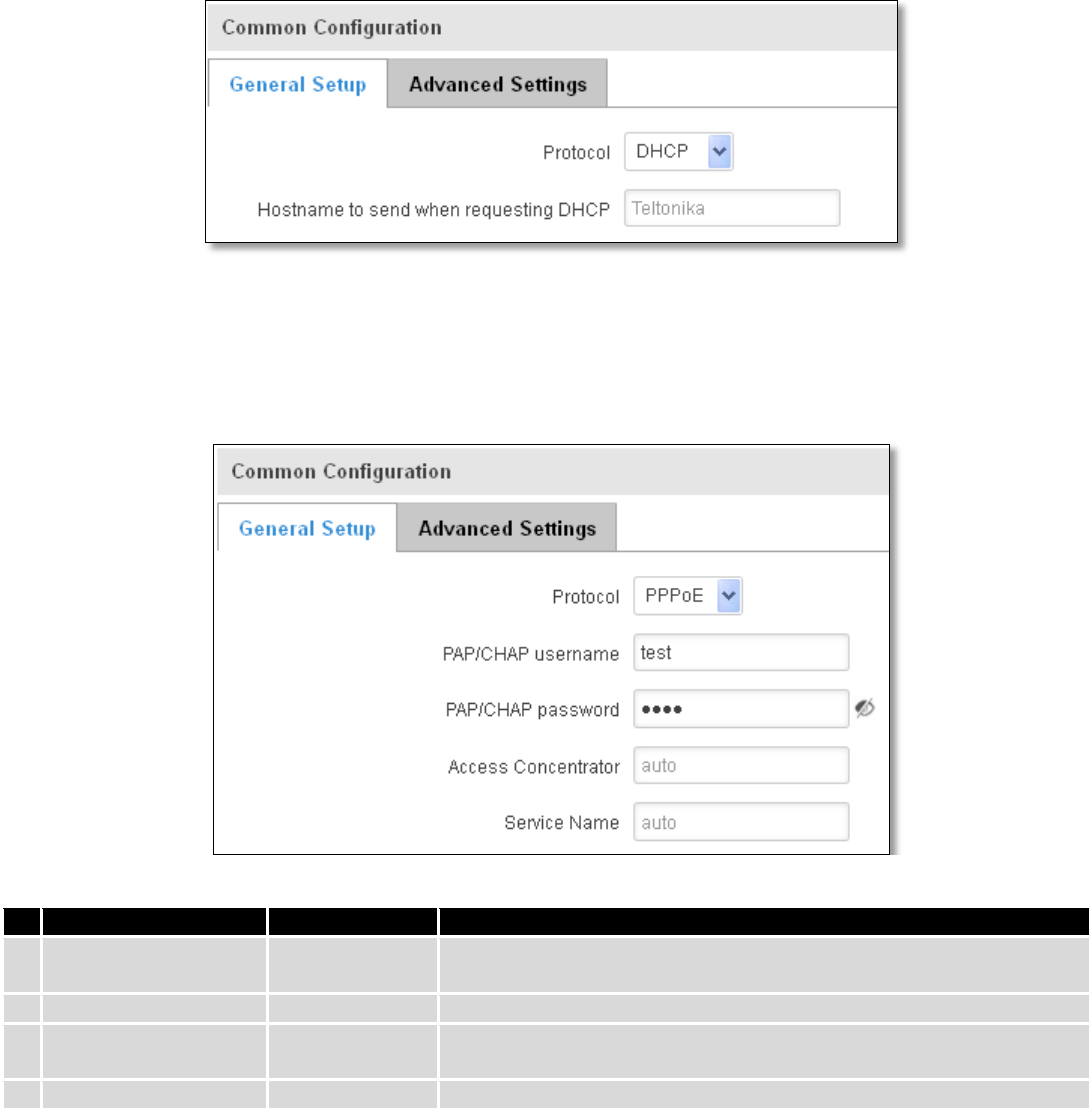
55
7.2.2.1.2 DHCP:
When you select the DHCP protocol you can use it as is, because most networks will not require any additional
advanced configuration.
7.2.2.1.3 PPPoE
This protocol is mainly used by DSL providers:
This is the configuration setup for when you select PPPoE protocol.
Filed name
Sample
Explanation
1.
PAP/CHAP username
test
Your username and password that you would use to connect to your
carriers network.
2.
PAP/CHAP password
your_password
A mask used to define how “large” the WAN network is
3.
Access Concentrator
auto
Specifies the name of access concentrator. Leave empty to auto
detect.
4.
Service Name
auto
Specifies the name of the service. Leave empty to auto detect.
7.2.2.2 Advanced
These are the advanced settings for each of the protocols, if you are unsure of how to alter these attributes it is
highly recommended to leave them to a trained professional:
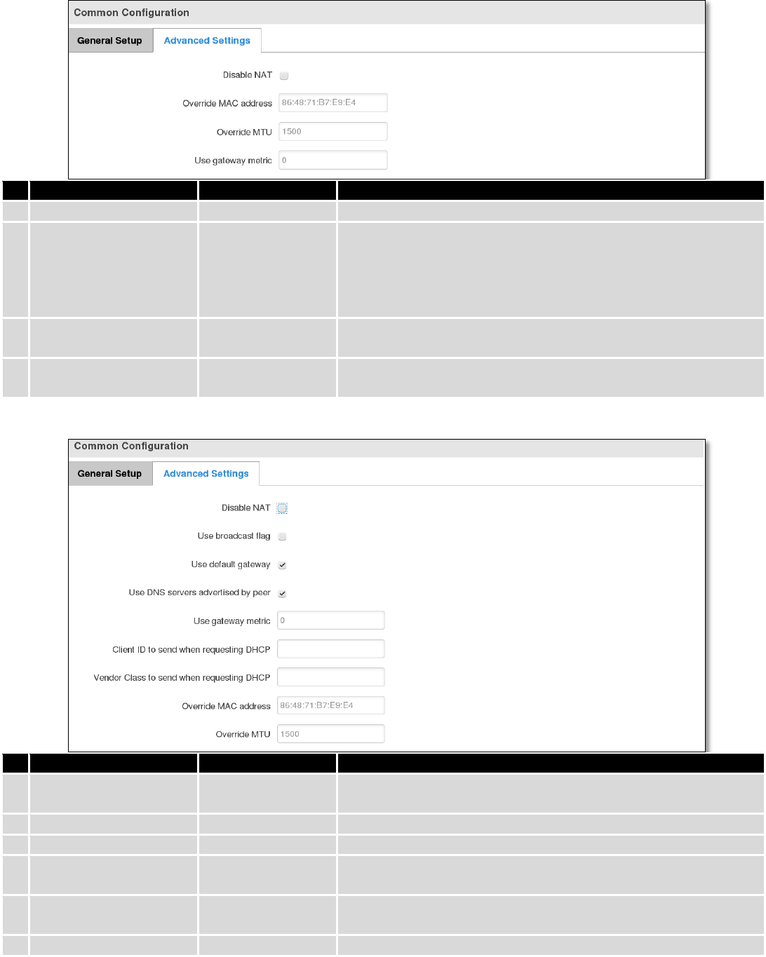
56
7.2.2.2.1 Static
Field name
Sample value
Explanation
1.
Disable NAT
On/Off
Toggle NAT on and off.
2
Override MAC address
86:48:71:B7:E9:E4
Override MAC address of the WAN interface. If your ISP gives you
a static IP address it might also bind it to your computers MAC
address (i.e. that IP will only work with your computer). In this
field you can enter your computers MAC address and fool the
gateway in thinking that it is communicating with your computer.
3.
Override MTU
1500
Maximum Transmission Unit – specifies the largest possible size
of a data packet.
4.
Use gateway metric
0
The WAN configuration by default generates a routing table
entry. With this field you can alter the metric of that entry.
7.2.2.2.2 DHCP
Field name
Sample value
Explanation
1.
Disable NAT
Enable/Disable
If checked, router will not perform NAT (masquerade) on this
interface
2
Use broadcast flag
Enable/Disable
Required for certain ISPs, e.g. Charter with DOCSIS 3
3.
Use default gateway
Enable/Disable
If unchecked, no default route is configured
4.
Use DNS server
advertised by peer
Enable/Disable
If unchecked, the advertised DNS server addresses are ignored
5.
User gateway metric
0
The WAN configuration by default generates a routing table entry
With this field you can alter the metric of that entry
6.
Client ID to send when
Specify client ID which will be sent when requesting DHCP
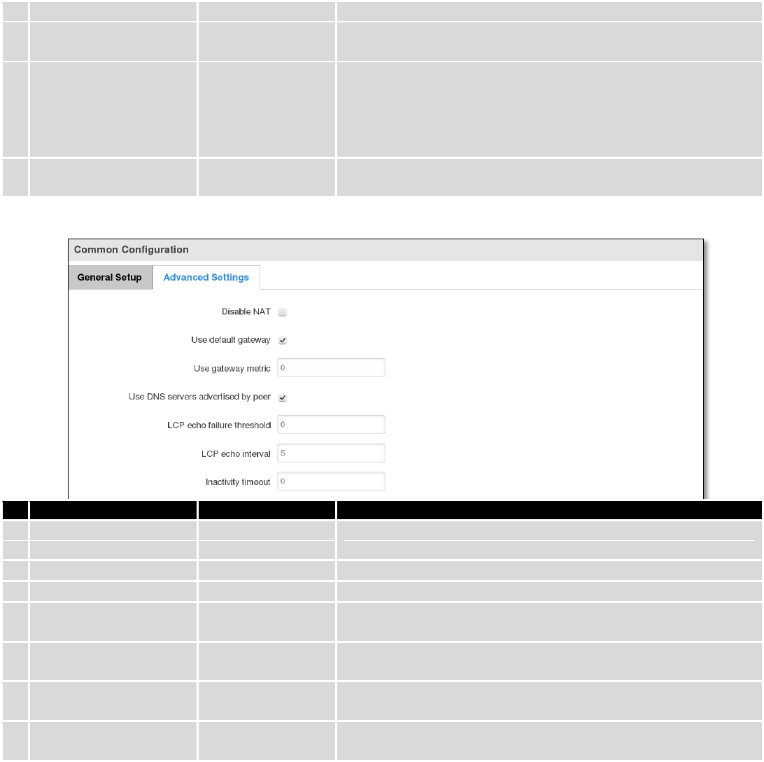
57
requesting DHCP
(Dynamic Host Configuration Protocol)
7.
Vendor Class to send
when requesting DHCP
Specify vendor class which be sent when requesting DHCP
(Dynamic Host Configuration Protocol)
8.
Override MAC address
86:48:71:B7:E9:E4
Override MAC address of the WAN interface. If your ISP gives you
a static IP address it might also bind it to your computers MAC
address (i.e. that IP will only work with your computer). In this
field you can enter your computers MAC address and fool the
gateway in thinking that it is communicating with your computer.
9.
Override MTU
1500
Maximum transmission unit – specifies the largest possible size of
a data packet.
7.2.2.2.3 PPPoE
Field name
Sample value
Explanation
1.
Disable NAT
Enable/Disable
If checked, router will not perform NAT (masquerade) on this
interface
2
Use default gateway
Enable/Disable
If unchecked, no default route is configured
3.
Use gateway metric
0
4.
Use DNS servers
advertised by peer
Enable/Disable
If unchecked, the advertised DNS server addresses are ignored
5.
LCP echo failure
threshold
0
Presume peer to be dead after given amount of LCP echo failures,
use 0 to ignore failures
6.
LCP echo interval
5
Send LCP echo requests at the given interval in seconds, only
effective in conjunction with failure threshold
7.
Inactivity timeout
0
Close inactive connection after the given amount of seconds, use
0 to persist connection
7.2.2.2.4 IP Aliases
IP aliases are a way of defining or reaching a subnet that works in the same space as the regular network.
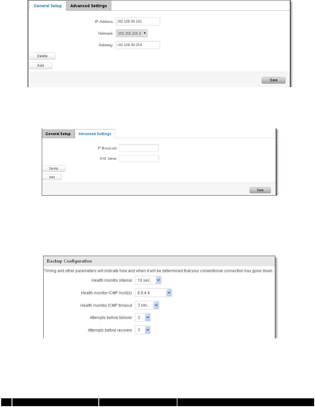
58
As you can see, the configuration is very similar to the static protocol; only in the example a 99th subnet is
defined. Now if some device has an IP in the 99 subnet (192.168.99.xxx) and the subnets gateway metric is “higher” and
the device is trying to reach the internet it will reroute it’s traffic not to the gateway that is defined in common
configurations but through the one that is specified in IP aliases.
You may also optionally define a broadcast address and a custom DNS server.
7.2.2.2.5 Backup WAN configuration
Backup WAN is function that allows you to back up your primary connection in case it goes down. There can be
two backup connections selected at the same time, in that case, when primary connection fails, router tries to use
backup with higher priority and if that is unavailable or fails too, then router tries the backup with lower priority.
The majority of the options consist of timing and other important parameters that help determine the health of
your primary connection. Regular health checks are constantly performed in the form of ICMP packets (Pings) on your
primary connection. When the connections state starts to change (READY->NOT READY and vice versa) a necessary
amount of failed or passed health checks has to be reached before the state changes completely. This delay is instituted
so as to mitigate “spikes” in connection availability, but it also extends the time before the backup link can be brought
up or down.
Field Name
Sample value
Explanation
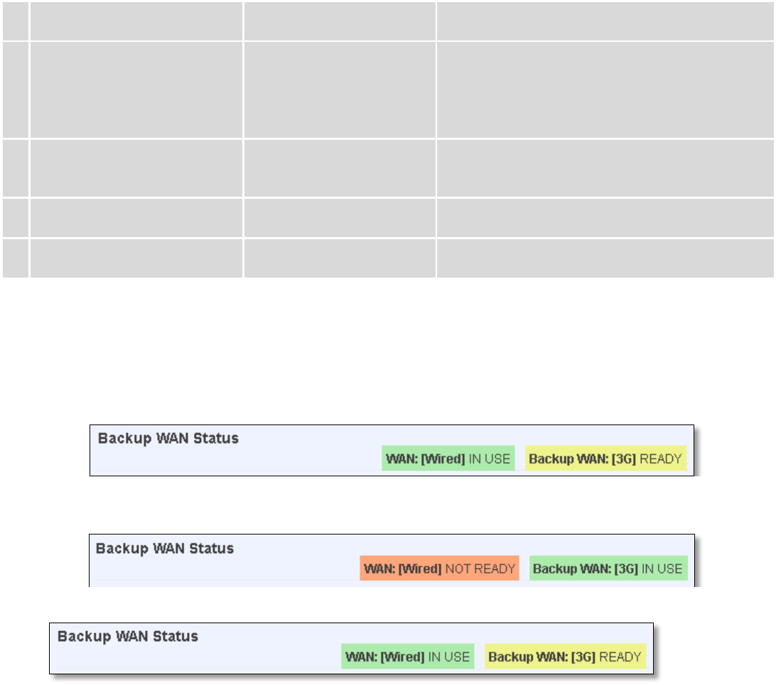
59
1.
Health monitor Interval
Disable/5/10/20/30/60/120
Seconds
The interval at which health checks are performed
2.
Health monitor ICMP host(s)
Disable/DNS Server(s)
/WAN GW/Custom
Where to Ping for a health check. As there is no
definitive way to determine when the connection
to internet is down for good, you’ll have to define
a host whose availability that of the internet as a
whole.
3.
Health monitor ICMP timeout
1/3/4/5/10 Seconds
How long to wait for an ICMP request to come
back. Set a higher value if your connection has
high latency or high jitter (latency spikes).
4.
Attempts before failover
1/3/5/10/15/20
How many checks should fail for your WAN
connection to be declared DOWN for good.
5.
Attempts before recovery
1/3/5/10/15/20
How many checks should pass for your WAN
connection to be declared UP.
7.2.2.3 How do I set up a backup link?
First we must select a main link and choose one or two backup links in WAN section. Then push the “Edit” button
and configure your WAN and Backup Wan settings to your liking. Click Save and wait until the settings are applied. Now
in the Status -> Network Information -> WAN page there should be a status indication for the backup WAN. If everything
is working correctly you should see something like this:
The above picture shows the status for Backup WAN configured on a wired main link. You can now simulate a
downed link by simply unplugging your Ethernet WAN cable. When you’ve done so you should see this:
And, if you plug the cable back in you should, again, see this:
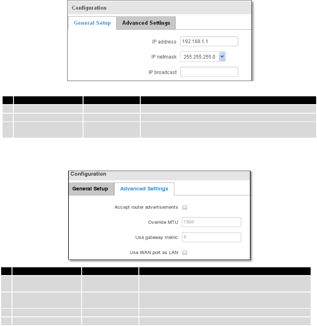
60
7.3 LAN
This page is used to configure the LAN network, where all your devices and computers that you connect to the
router will reside.
7.3.1 Configuration
7.3.1.1 General Setup
Field name
Sample value
Explanation
1.
IP address
192.168.1.1
Address that the router uses on the LAN network
2
IP netmask
255.255.255.0
A mask used to define how large the LAN network is
3.
IP broadcast
IP broadcasts are used by BOOTP and DHCP clients to find and
send requests to their respective servers
7.3.1.2 Advanced settings
Field name
Sample value
Explanation
1.
Accept router
advertisements
Enable/Disable
If enabled allows accepting router advertisements (Disabled by
default)
2.
Override MTU
1500
MTU (Maximum Transmission Unit) specifies the largest
possible size of a data packet
3.
Use gateway metric
0
With this field you can alter the metric of that entry
4.
Use WAN port as LAN
Enable/Disable
Enable/disable WAN port using as LAN port
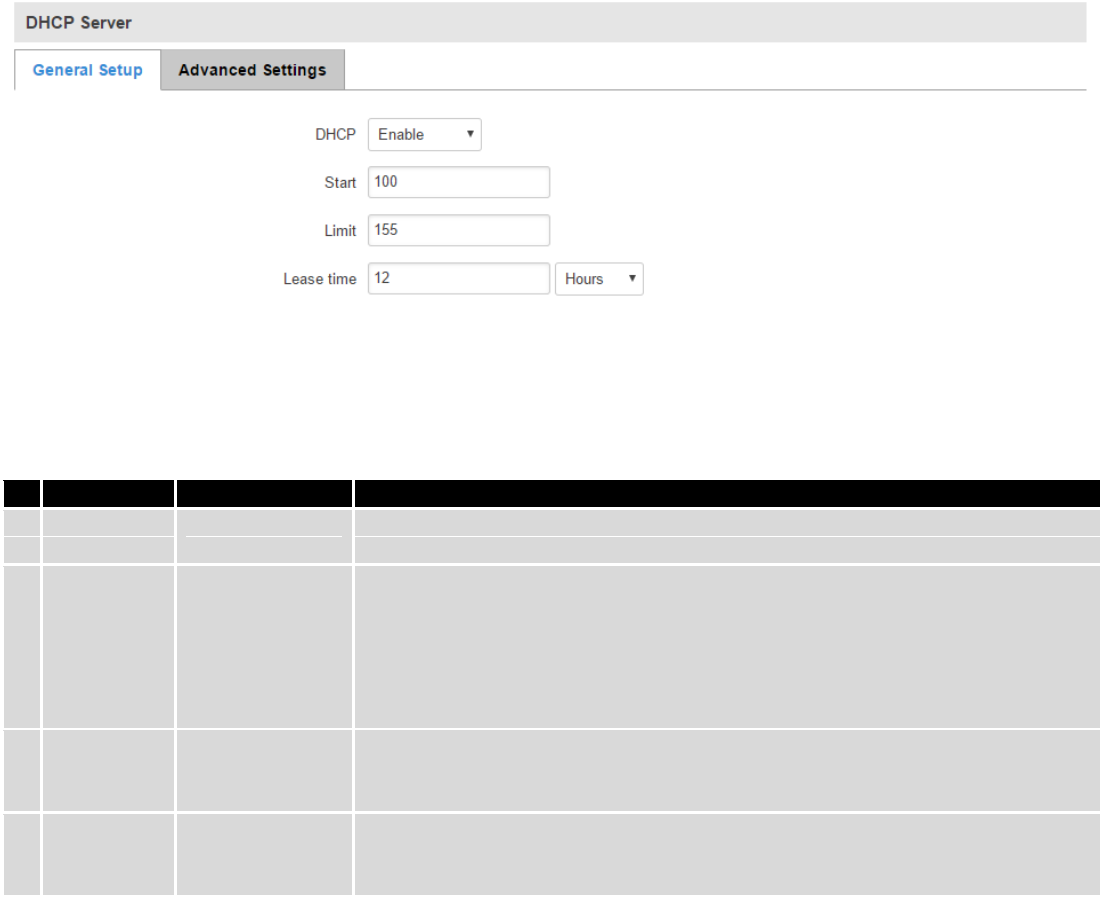
61
7.3.2 DHCP Server
The DHCP server is the router side service that can automatically configure the TCP/IP settings of any device that
requests such a service. If you connect a device that has been configured to obtain IP address automatically the DHCP
server will lease an IP address and the device will be able to fully communicate with the router.
7.3.2.1 General Setup
Field Name
Sample value
Explanation
1.
DHCP
Enable / Disable/
DHCP Relay
Manage DHCP server
2.
Start
100
The starting address of the range that the DHCP server can use to give out to
devices. E.g.: if your LAN IP is 192.168.2.1 and your subnet mask is 255.255.255.0
that means that in your network a valid IP address has to be in the range of
[192.168.2.1 – 192.168.2.254](192.168.2.0 and 192.168.2.255 are special
unavailable addresses). If the Start value is set to 100 then the DHCP server will
only be able to lease out addresses starting from 192.168.2.100
3.
Limit
155
How many addresses the DHCP server gets to lease out. Continuing on the above
example: if the start address is 192.168.2.100 then the end address will be
192.168.2.254 (100 + 155 – 1 = 254).
4.
Lease time
12
How long can a leased IP be considered valid. An IP address after the specified
amount of time will expire and the device that leased it out will have to request
for a new one. Select Hour or Minute (minimum 2min).
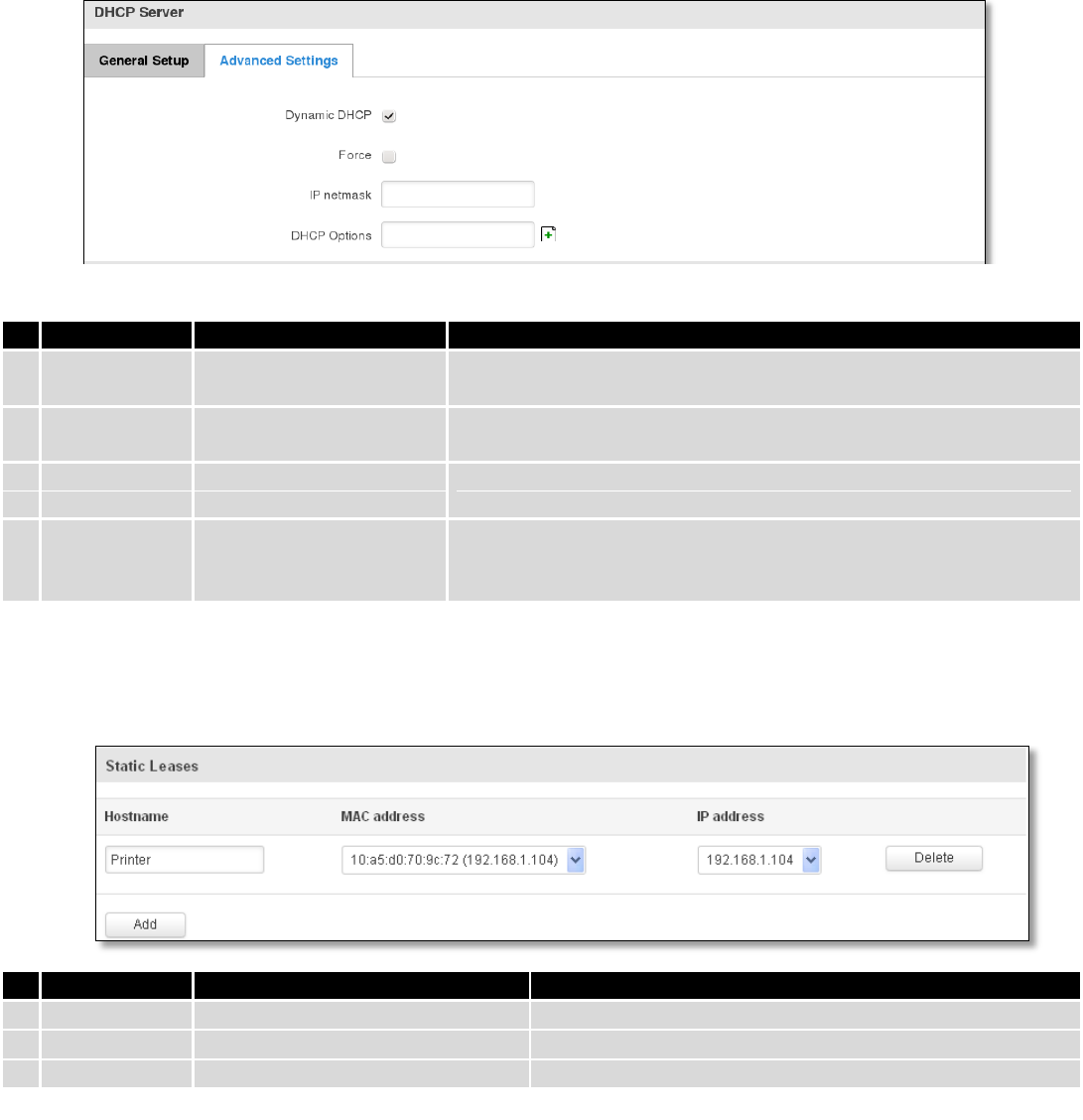
62
7.3.2.2 Advanced settings
You can also define some advanced options that specify how the DHCP server will operate on your LAN network.
7.3.2.3 Static Leases
This page is used to configure static IP leases.
7.3.2.4 IP Aliases
7.3.2.4.1 General Setup
IP aliases are the way of defining or reaching a subnet that works in the same space as the regular network.
Field Name
Sample Value
Explanation
1.
Dynamic DHCP
Checked/Unchecked
Dynamically allocate client addresses, if set to 0 only clients present
in the ethers files are served
2.
Force
Checked/Unchecked
Forces DHCP serving even if another DHCP server is detected on the
same network segment.
3.
IP netmask
You can override your LAN netmask here to make the DHCP server
think it’s serving a larger or a smaller network than it actually is.
4.
DHCP Options
Additional options to be added for this DHCP server. For example
with '26,1470' or 'option:mtu, 1470' you can assign an MTU per
DHCP. Your client must accept MTU by DHCP for this to work.
Field Name
Sample Value
Explanation
1.
Hostname
Printer
Name which will be linked with IP address.
2.
MAC address
10:a5:d0:70:9c:72 (192.168.1.104)
Device MAC address
3.
IP address
192.168.1.104
Device IP address
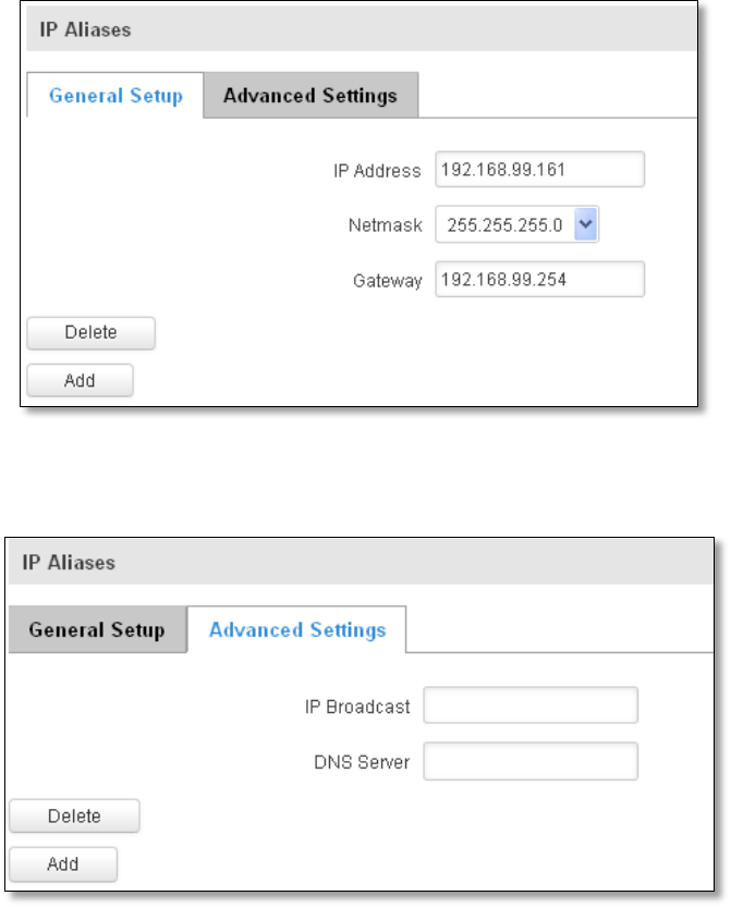
63
7.3.2.4.2 Advanced Settings
You may also optionally define a broadcast address and a custom DNS server.
7.4 Wireless
On this page you can configure your wireless settings. Depending on whether your WAN mode is set to Wi-Fi or
not, the page will display either the options for configuring an Access Point or options for configuring a connection to
some local access point.
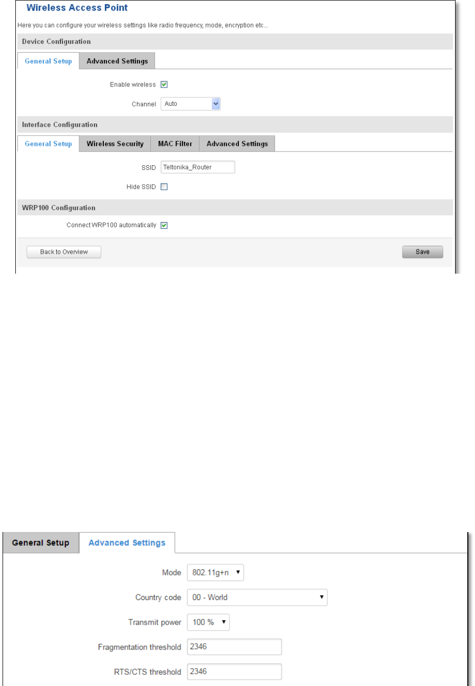
64
Access Point:
Here you can see the Overview of the wireless configuration. It is divided into two main sections – device and
interface. One is dedicated to configuring hardware parameters other – software.
Here you can toggle the availability of the wireless radio and the physical channel frequency.
Important note: As seen in the picture you should always Save before toggling the radio on and off.
SSID – Your wireless networks identification string. This is the name of your Wi-Fi network. When other Wi-Fi
capable computers or devices scan the area for Wi-Fi networks they will see your network with this name.
Hide SSID – Will render your SSID hidden from other devices that try to scan the area.
Connect to WRP100 automatically – let Teltonika WRP100 wireless repeater connect to this router automatically.
7.4.1.1 Device
7.4.1.1.1 Advanced Settings
Here you can configure more advanced parameters:
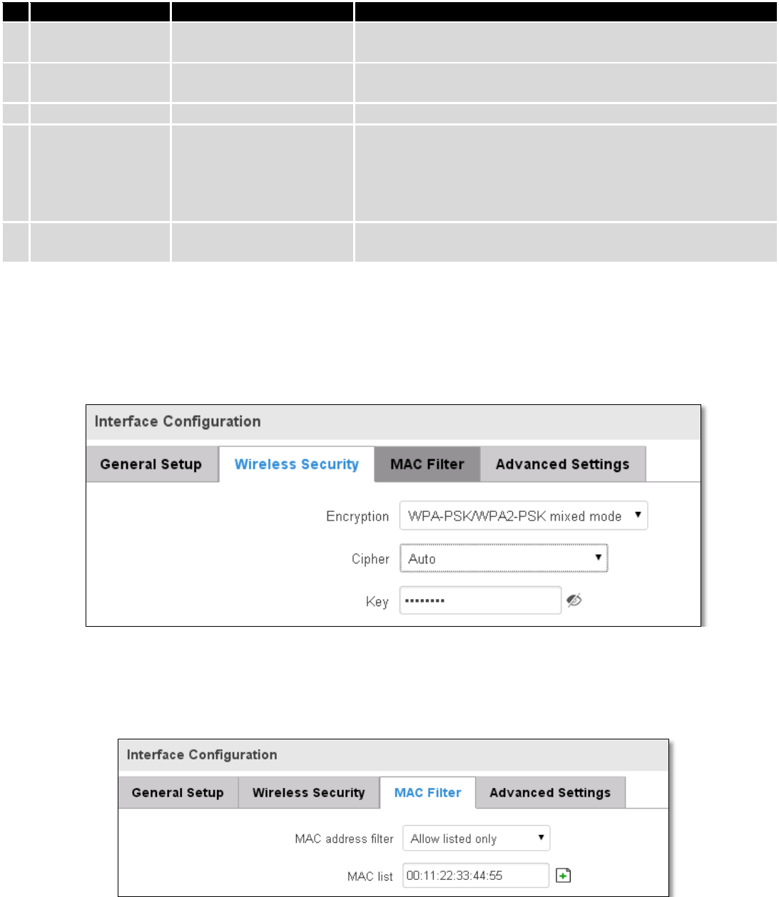
65
Field name
Sample value
Explanation
1.
Mode
Auto, b, g, g+n
Different modes provide different throughput and security
options.
2.
Country Code
Any ISO/IEC 3166 alpha2
country code
Selecting this will help the wireless radio configure its internal
parameters to meet your countries wireless regulations.
3.
Transmit power
20%/40%/60%/80%/100%
Select Wi-Fi signal power
4.
Fragmentation
threshold
2346
The smallest packet size that can be fragmented and
transmitted by multiple frames. In areas were interference is a
problem, setting a lower fragment threshold might help reduce
the probability of unsuccessful packet transfers, thus increasing
speed.
5.
RTS/CTS Threshold
2346
Request to send threshold. It can help resolve problems arising
when several access points are in the same area, contending.
7.4.1.2 Interface
7.4.1.2.1 Security
Encryption – there are many modes of encryption, a distinctive classis pointed out below.
First select an encryption method: TKIP, CCMP, TKIP&CCMP and auto. Note: Some authentication methods won’t
support TKIP (and TKIP&CCMP) encryption. After you’ve selected your encryption method, you should enter your pass
phrase, which must be at least 8 characters long.
7.4.1.2.2 MAC-Filter
Filter – you can define a rule for what to do with the MAC list you’ve defined. You can either allow only the listed
MACs or allow ALL, but forbid only the listed ones.
7.4.1.2.3 Advanced settings
Separate clients – prevents Wi-Fi clients from communicating with each other on the same subnet.
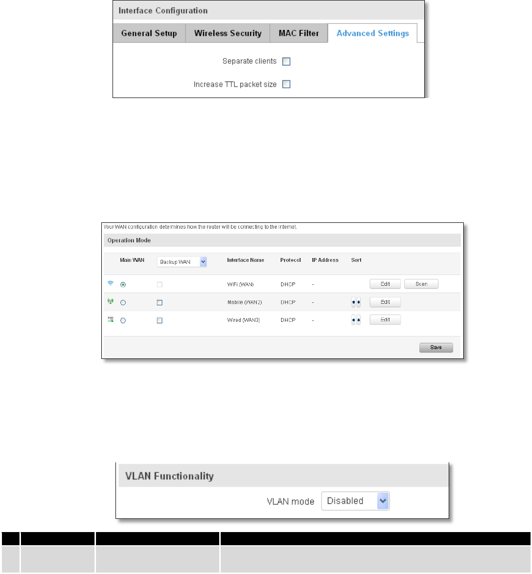
66
Increase TTL packet size – increase TTL packet size for incoming packets.
7.4.1.3 Client
RUT9xx can work as a Wi-Fi client. Client mode is nearly identical to AP, except for the fact that most for the
options are dictated by the wireless access point that the router is connecting to. Changing them can result in an
interrupted connection to an AP.
In addition to standard options you can also click the Scan button to rescan the surrounding area and attempt to
connect to a new wireless access point.
7.5 VLAN
On this page you can configure your Virtual LAN settings, either Port based or Tag based.
7.5.1 VLAN Networks
7.5.1.1 VLAN Functionality
Field Name
Sample Value
Explanation
1.
VLAN mode
Disabled / Port based /
Tag based
Lets user to choose the VLAN mode or disable VLAN functionality.
7.5.1.2 VLAN Network List
If VLAN mode – Port based:
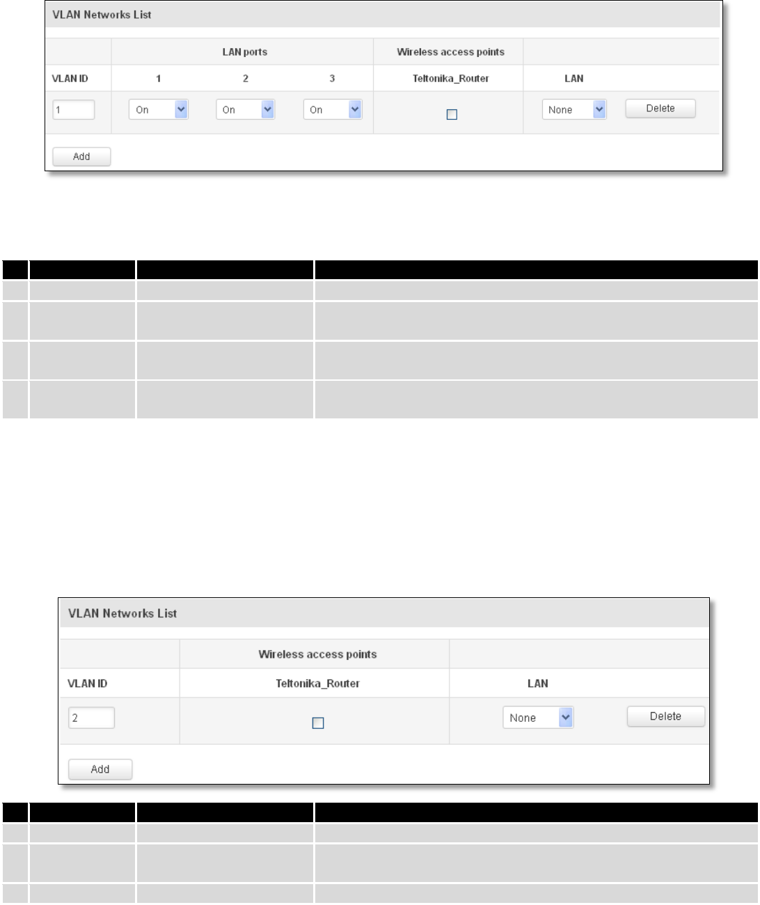
67
Field Name
Sample Value
Explanation
1.
VLAN ID
1
VLAN Identification number, allowed in range (1-4094)
2.
LAN ports
1 / 2 / 3
on
Switches each LAN port between ON, OFF or tagged state.
3.
Wireless
access points
Enabled / Disabled
Assign selected access point(s) to selected LAN.
4.
LAN
None
Select to which LAN to assign selected LAN ports and wireless access
points.
If VLAN mode – Tag based:
Field Name
Sample Value
Explanation
1.
VLAN ID
2
VLAN Identification number, allowed in range (1-4094)
3.
Wireless
access points
Enabled / Disabled
Assign selected access point(s) to selected LAN.
4.
LAN
None
Select to which LAN to wireless access point(s).
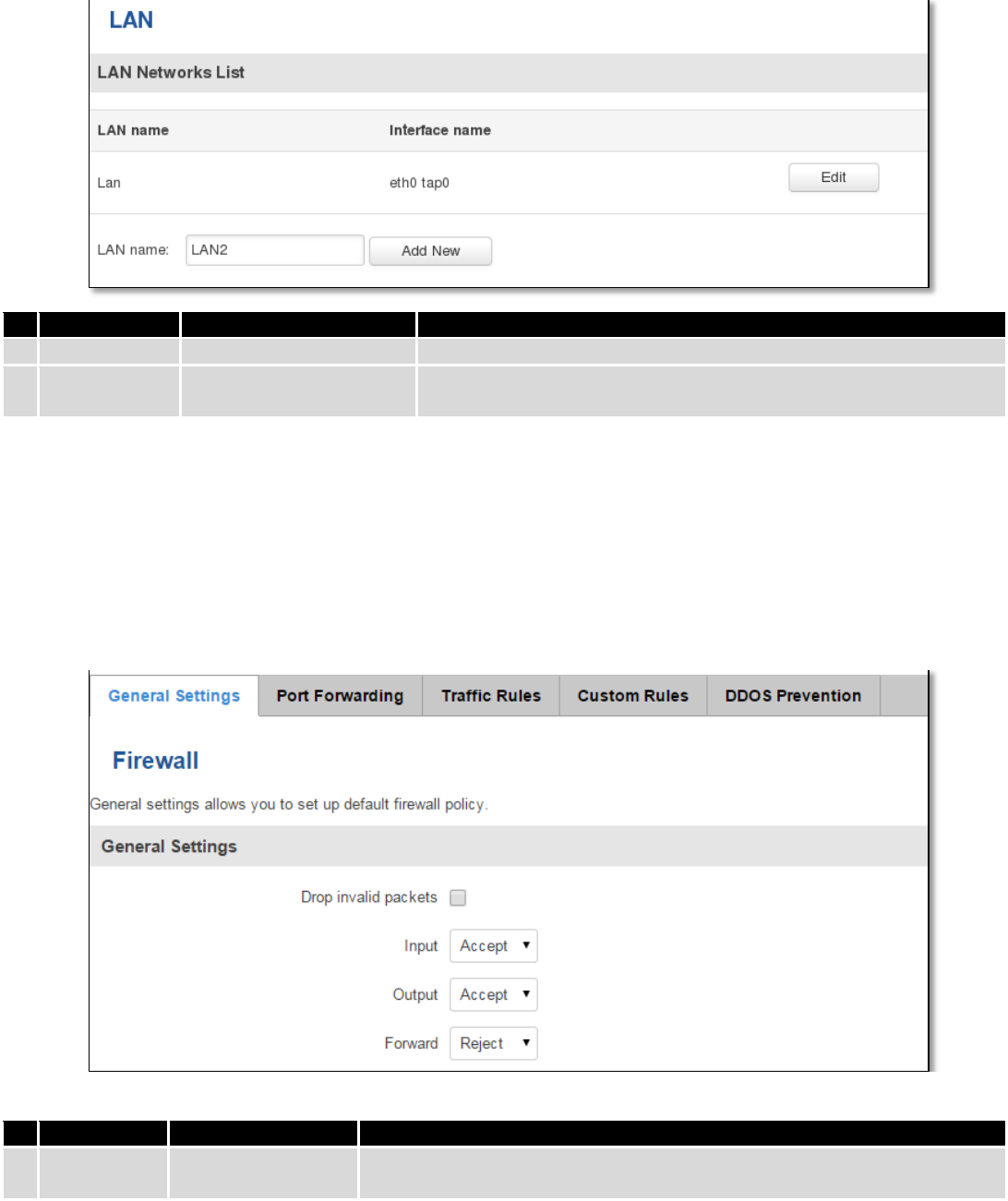
68
7.5.2 LAN Networks
In this page you can create extra LAN networks, and assign them with LAN Ports and wireless access points. You
can get extra information on how to configure any of your LAN’s settings in section – 7.3 LAN
Field Name
Sample Value
Explanation
1.
LAN name
Lan
Specifies new LAN name
2.
Interface
name
eth0 tap0
Specifies LAN interface name
7.6 Firewall
In this section we will look over the various firewall features that come with RUT9.
7.6.1 General Settings
The routers firewall is a standard Linux iptables package, which uses routing chains and policies to facilitate
control over inbound and outbound traffic.
Field Name
Sample value
Explanation
1.
Drop Invalid
packets
Checked/Unchecked
A “Drop” action is performed on a packet that is determined to be invalid
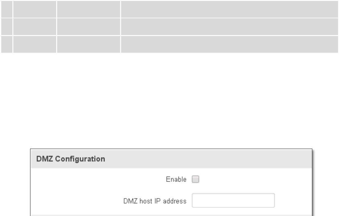
69
2.
Input
Reject/Drop/Accept
DEFAULT* action that is to be performed for packets that pass through the
Input chain.
3.
Output
Reject/Drop/Accept
DEFAULT* action that is to be performed for packets that pass through the
Output chain.
4.
Forward
Reject/Drop/Accept
DEFAULT* action that is to be performed for packets that pass through the
Forward chain.
*DEFAULT: When a packet goes through a firewall chain it is matched against all the rules for that specific chain. If
no rule matches said packet, an according Action (either Drop or Reject or Accept) is performed.
Accept – Packet gets to continue down the next chain.
Drop – Packet is stopped and deleted.
Reject – Packet is stopped, deleted and, differently from Drop, an ICMP packet containing a message of rejection
is sent to the source of the dropped packet.
7.6.2 DMZ
By enabling DMZ for a specific internal host (for e.g.: your computer), you will expose that host and its services to
the routers WAN network (i.e. - internet).
7.6.3 Port Forwarding
Here you can define your own port forwarding rules.
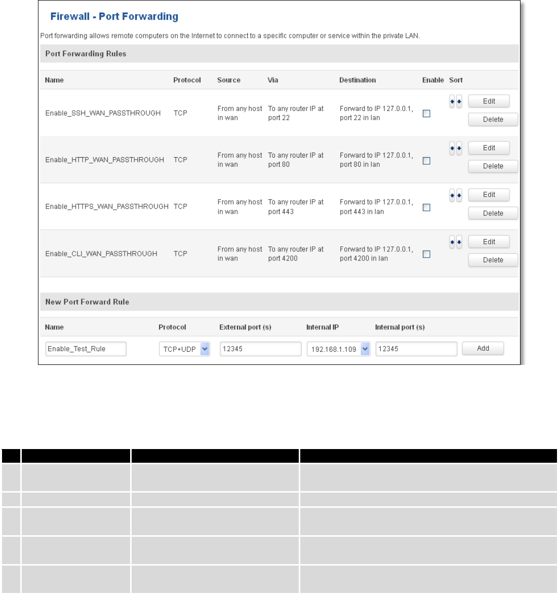
70
You can use port forwarding to set up servers and services on local LAN machines. The above picture shows how
you can set up a rule that would allow a website that is being hosted on 192.168.1.109, to be reached from the outside
by entering http://routersExternalIp:12345/.
Field Name
Sample value
Explanation
1.
Name
Enable_SSH_WAN_PASSTHROUGH
Name of the rule. Used purely to make it easier to
manage rules.
2.
Protocol
TCP/UDP/TCP+UDP/Other
Type of protocol of incoming packet.
3.
External Port
1-65535
From this port on the WAN network the traffic will be
forwarded.
4.
Internal IP address
IP address of some computer on
your LAN
The IP address of the internal machine that hosts
some service that we want to access from the outside.
5.
Internal port
1-65535
To that port on the internal machine the rule will
redirect the traffic.
When you click edit you can fine tune a rule to near perfection, if you should desire that.
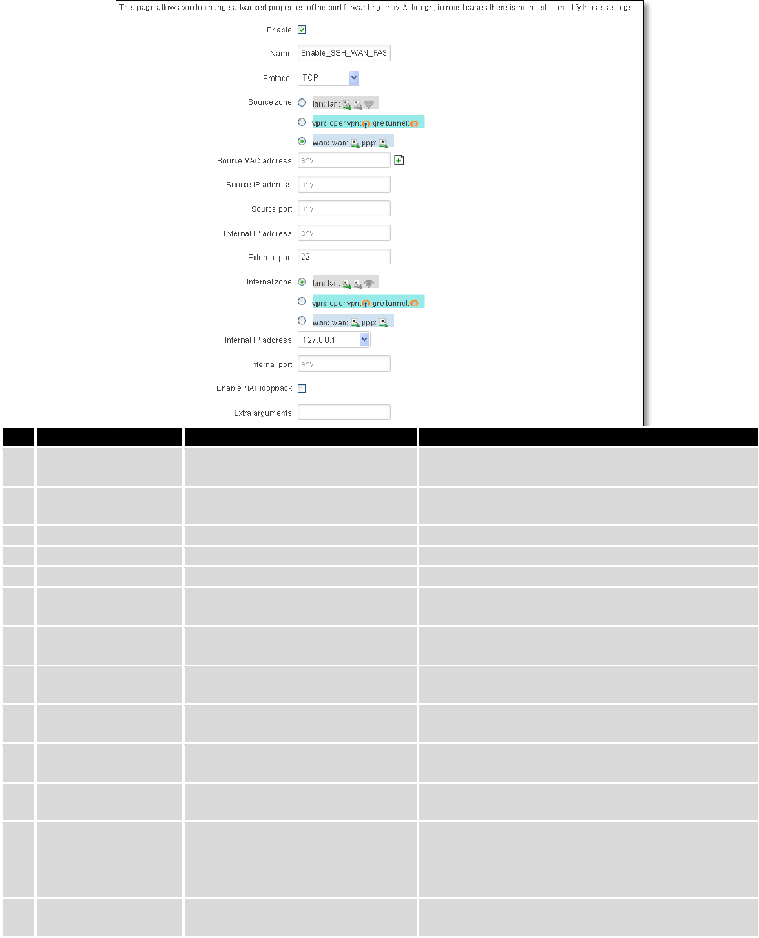
71
Field Name
Sample value
Explanation
1.
Name
ENABLE_SSH_WAN_PASSTHROUGH
Name of the rule. Used purely to make it easier to
manage rules.
2.
Protocol
TCP/UDP/TCP+
UDP/ICMP/Custom
You may specify multiple by selecting (custom) and
then entering protocols separated by space
3.
Source zone
LAN/VPN/WAN
Match incoming traffic from this zone only
4.
Source MAC address
any
Match incoming traffic from these MACs only
5.
Source IP address
any
Match incoming traffic from this IP or range only
7.
Source port
any
Match incoming traffic originating from the given
source port or port range on the client host only
8.
External IP address
any
Match incoming traffic directed at the given IP
address only
9.
External port
22
Match incoming traffic directed at the given
destination port or port range on this host only
10.
Internal zone
LAN/VPN/WAN
Redirect matched incoming traffic to the specified
internal zone
11.
Internal IP address
127.0.0.1
Redirect matched incoming traffic to the specified
internal host
12.
Internal port
any
Redirect matched incoming traffic to the given port
on the internal host
13.
Enable NAT loopback
Enable/Disable
NAT loopback enables your local network (i.e.
behind your router/modem) to connect to a
forward-facing IP address (such as 208.112.93.73) of
a machine that it also on your local network
14.
Extra arguments
Passes additional arguments to iptables. Use with
care!
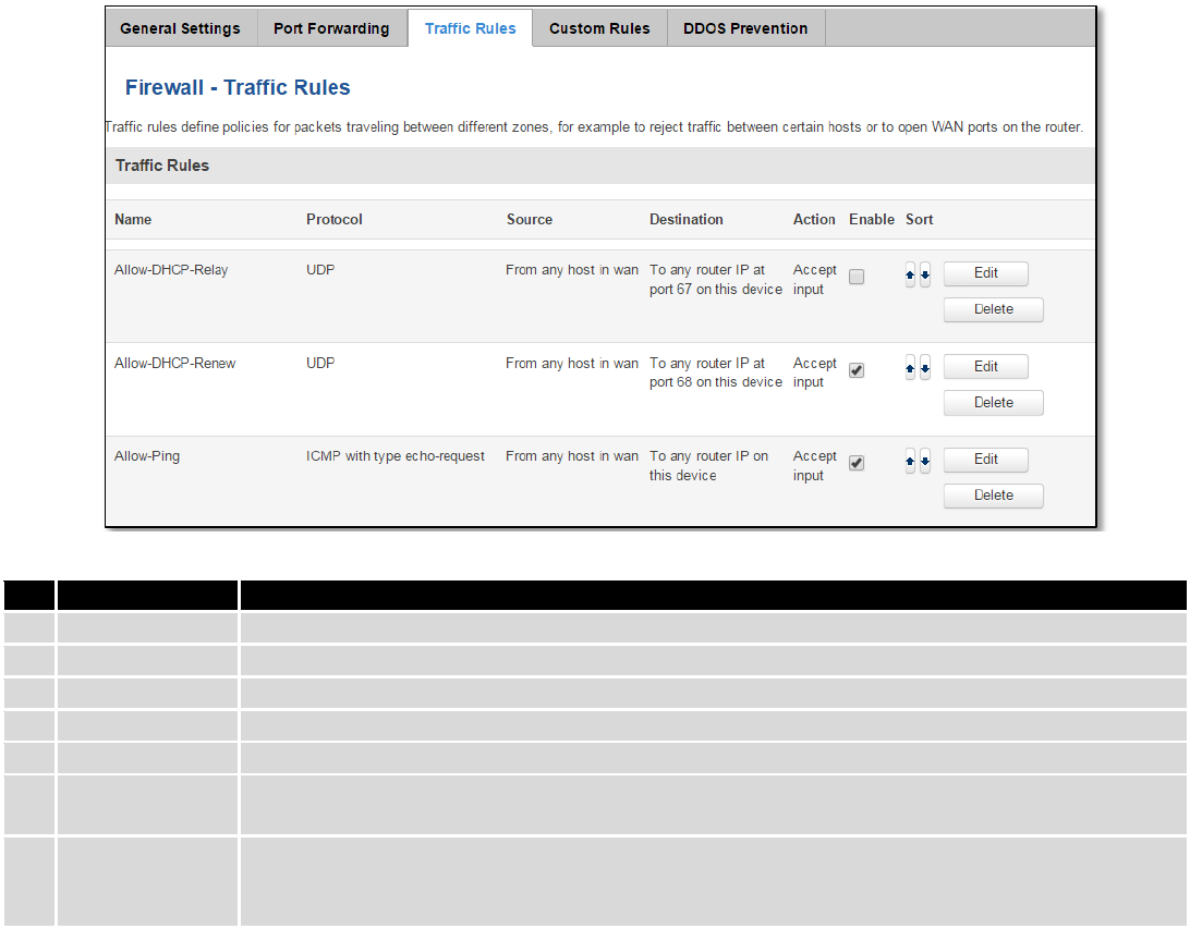
72
7.6.4 Traffic Rules
The traffic rule page contains a more generalized rule definition. With it you can block or open ports, alter how
traffic is forwarded between LAN and WAN and many more things.
Field Name
Explanation
1.
Name
Name of the rule. Used for easier rules management purpose only
2.
Protocol
Protocol type of incoming or outgoing packet
3.
Source
Match incoming traffic from this IP or range only
4.
Destination
Redirect matched traffic to the given IP address and destination port
5.
Action
Action to be taken for the packet if it matches the rule
6.
Enable
Self-explanatory. Uncheck to make the rule inactive. The rule will not be deleted, but it also
will not be loaded into the firewall.
7.
Sort
When a packet arrives, it gets checked for a matching rule. If there are several rules that
match the rule, the first one is applied i.e. the order of the rule list impacts how your firewall
operates, therefore you are given the ability to sort your list as you wish.
You can configure firewall rule by clicking edit button.
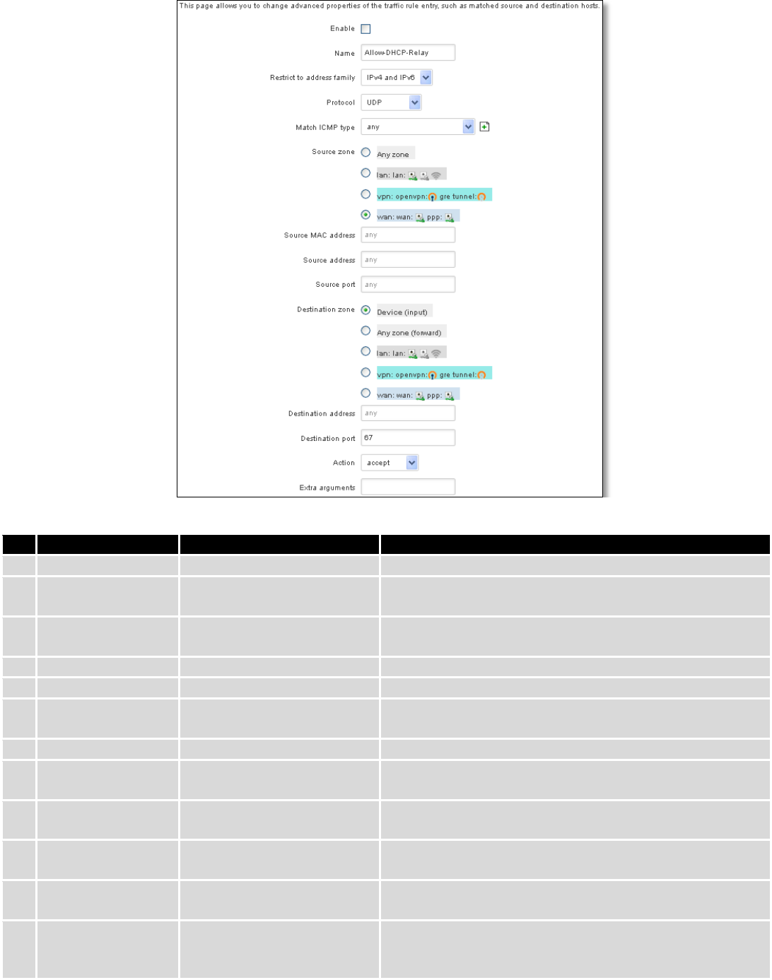
73
Field Name
Sample value
Explanation
1.
Name
“Allow-DHCP-Relay”
Used to make rule management easier
2.
Restrict to address
family
IPv4 and IPV6
Match traffic from selected address family only
3.
Protocol
TCP/UDP/Any/ICMP/Custom
Protocol of the packet that is being matched against traffic
rules.
4.
Match ICMP type
any
Match traffic with selected ICMP type only
5.
Source zone
any zone/LAN/VPN/WAN
Match incoming traffic from this zone only
6.
Source MAC
address
any
Match incoming traffic from these MACs only
7.
Source address
any
Match incoming traffic from this IP or range only
8.
Source port
any
Match incoming traffic originating from the given source
port or port range on the client host only
9.
Destination zone
Device/Any
zone/LAN/VPN/WAN
Match forwarded traffic to the given destination zone only
10.
Destination address
any
Match forwarded traffic to the given destination IP address
or IP range only
11.
Destination port
67
Match forwarded traffic to the given destination port or
port range only
12.
Action
Drop/Accept/Reject + chain
+ additional rules
Action to be taken on the packet if it matches the rule. You
can also define additional options like limiting packet
volume, and defining to which chain the rule belongs
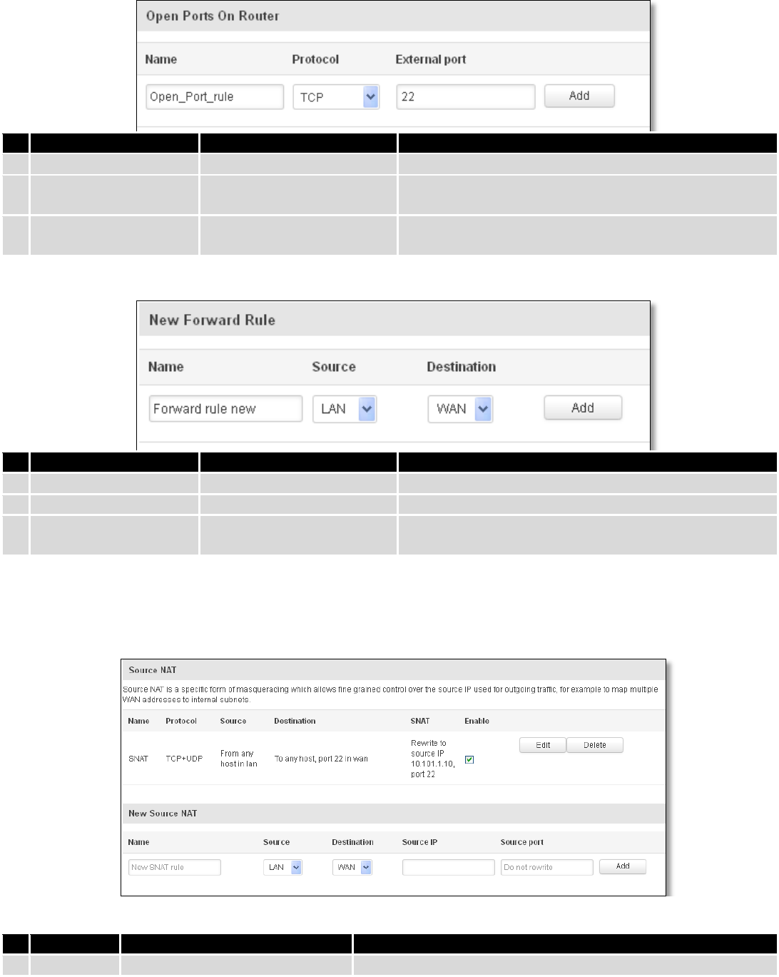
74
7.6.4.1 Open Ports On the Router
Field Name
Sample value
Explanation
1.
Name
Open_Port_rule
Used to make rule management easier
2.
Protocol
TCP/UDP/Any/ICMP/Custom
Protocol of the packet that is being matched against
traffic rules.
3.
External port
1-65535
Match incoming traffic directed at the given destination
port or port range on this host.
7.6.4.2 New Forward Rule
Field Name
Sample value
Explanation
1.
Name
Forward rule new
Used to make rule management easier
2.
Source
LAN/VPN/WAN
Match incoming traffic from selected address family only
3.
Protocol
TCP/UDP/Any/ICMP/Custom
Protocol of the packet that is being matched against
traffic rules.
7.6.4.3 Source NAT
Source NAT is a specific form of masquerading which allows fine grained control over the source IP used for
outgoing traffic, for example to map multiple WAN addresses to internal subnets.
Field Name
Sample value
Explanation
1.
Name
SNAT
Used to make rule management easier
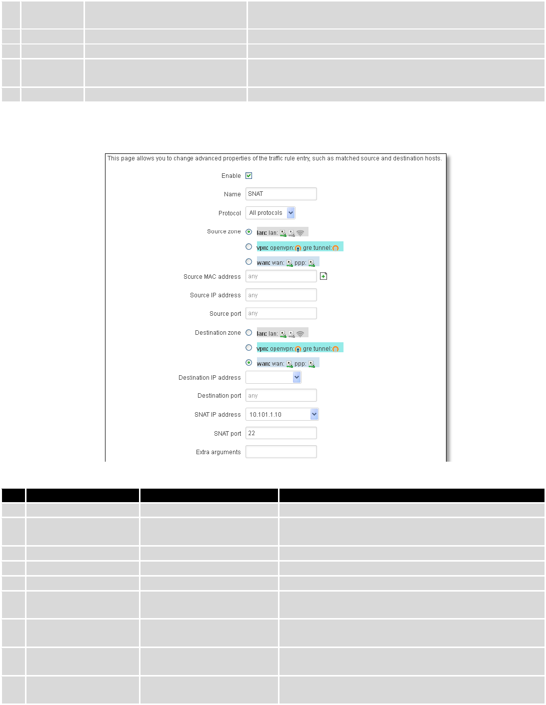
75
2.
Protocol
TCP/UDP/Any/ICMP/Custom
Protocol of the packet that is being matched against traffic
rules.
3.
Source
LAN/VPN/WAN
Match incoming traffic from selected address family only
4.
Destination
LAN/VPN/WAN
Forward incoming traffic to selected address family only
5.
SNAT
Rewrite to source IP 10.101.1.10
SNAT (Source Network Address Translation) rewrite packet\'s
source IP address and port
6.
Enable
Enable/Disable
Make a rule active/inactive
You can configure firewall source NAT rule, by clicking edit button.
Field Name
Sample value
Explanation
1.
Name
SNAT
Used to make rule management easier
2.
Protocol
TCP/UDP/Any/ICMP/Custom
Protocol of the packet that is being matched against
traffic rules.
3.
Source zone
LAN/VPN/WAN
Match incoming traffic from this zone only
4.
Source MAC address
any
Match incoming traffic from these MACs only
5.
Source address
any
Match incoming traffic from this IP or range only
6.
Source port
any
Match incoming traffic originating from the given source
port or port range on the client host only
7.
Destination zone
LAN/VPN/WAN
Match forwarded traffic to the given destination zone
only
8.
Destination IP address
Select from the list
Match forwarded traffic to the given destination IP
address or IP range only
9.
Destination port
any
Match forwarded traffic to the given destination port or
port range only
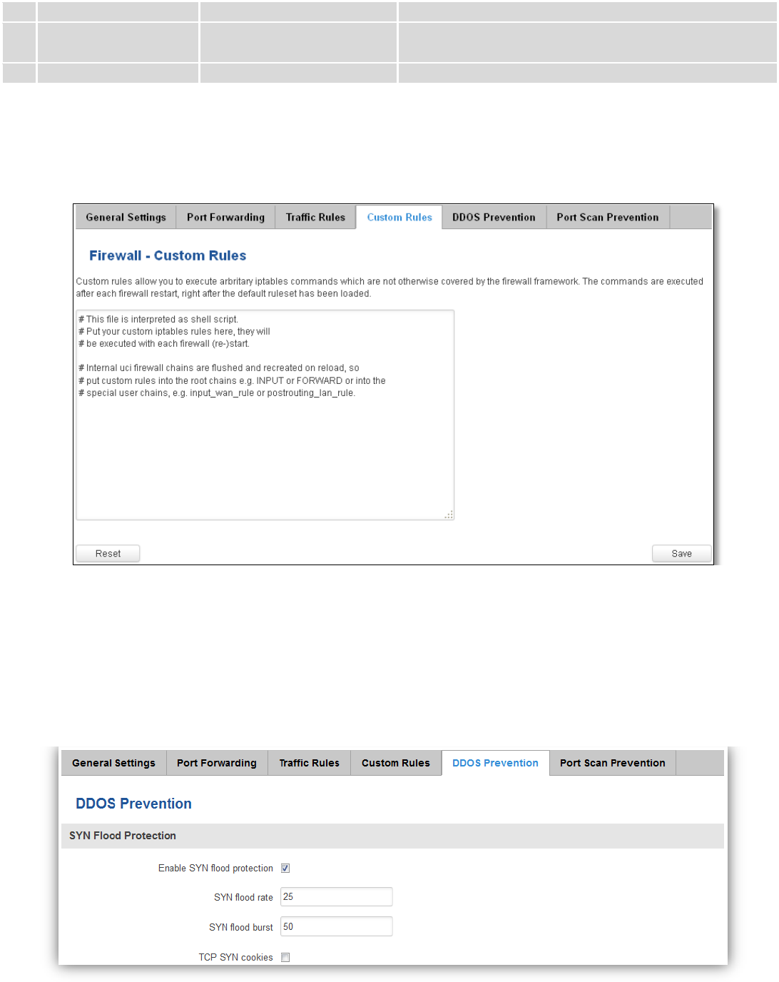
76
10.
SNAT IP address
“10.101.1.10”
Rewrite matched traffic to the given IP address
11.
SNAT port
“22”
Rewrite matched traffic to the given source port. May be
left empty to only rewrite the IP address'
12.
Extra arguments
Passes additional arguments to iptables. Use with care!
7.6.5 Custom Rules
Here you have the ultimate freedom in defining your rules – you can enter them straight into the iptables
program. Just type them out into the text field ant it will get executed as a Linux shell script. If you are unsure of how to
use iptables, check out the internet for manuals, examples and explanations.
7.6.6 DDOS Prevention
7.6.6.1 SYN Flood Protection
SYN Flood Protection allows you to protect from attack that exploits part of the normal TCP three-way handshake
to consume resources on the targeted server and render it unresponsive. Essentially, with SYN flood DDoS, the offender
sends TCP connection requests faster than the targeted machine can process them, causing network saturation.
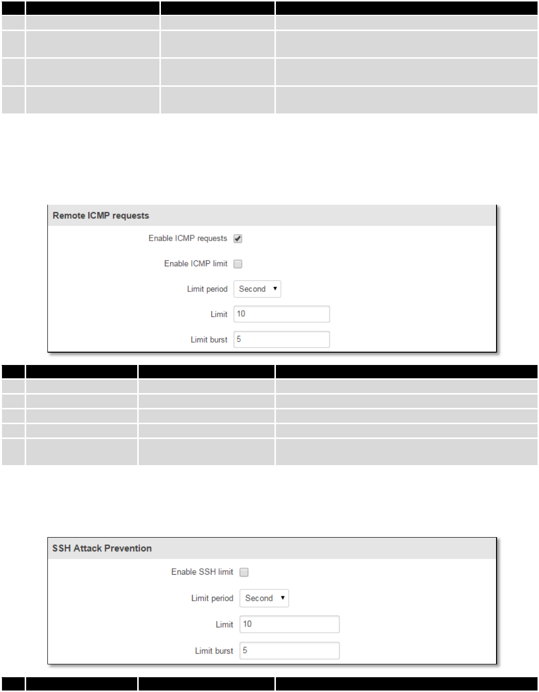
77
Field Name
Sample value
Explanation
1.
Enable SYN flood protection
Enable/Disable
Makes router more resistant to SYN flood attacks.
2.
SYN flood rate
“25”
Set rate limit (packets/second) for SYN packets above
which the traffic is considered a flood.
3.
SYN flood burst
“50”
Set burst limit for SYN packets above which the traffic is
considered a flood if it exceeds the allowed rate.
4.
TCP SYN cookies
Enable/Disable
Enable the use of SYN cookies (particular choices of
initial TCP sequence numbers by TCP servers).
7.6.6.2 Remote ICMP requests
Attackers are using ICMP echo request packets directed to IP broadcast addresses from remote locations to
generate denial-of-service attacks.
Field Name
Sample value
Explanation
1.
Enable ICMP requests
Enable/Disable
Blocks remote ICMP echo-request type
2.
Enable ICMP limit
Enable/Disable
Enable ICMP echo-request limit in selected period
3.
Limit period
Second/Minute/Hour/Day
Select in what period limit ICMP echo-request
4.
Limit
“10”
Maximum ICMP echo-request during the period
5.
Limit burst
“5”
Indicating the maximum burst before the above limit
kicks in.
7.6.6.3 SSH Attack Prevention
Prevent SSH (Allows a user to run commands on a machine's command prompt without them being physically
present near the machine.) attacks by limiting connections in defined period.
Field Name
Sample value
Explanation
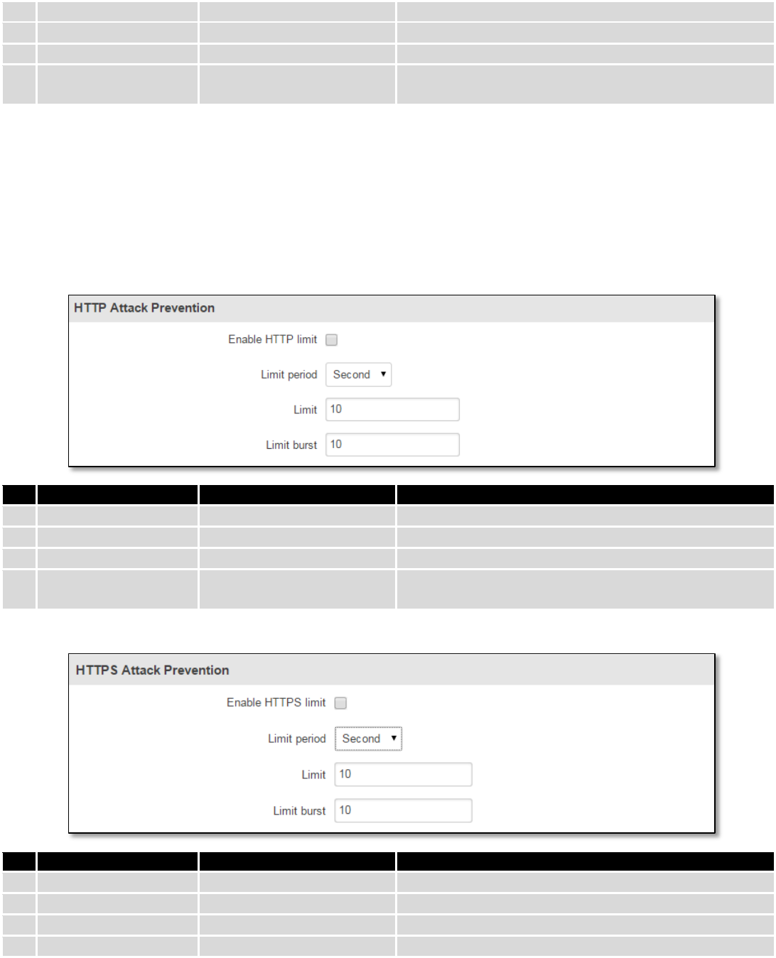
78
1.
Enable SSH limit
Enable/Disable
Enable SSH connections limit in selected period
2.
Limit period
Second/Minute/Hour/Day
Select in what period limit SSH connections
3.
Limit
“10”
Maximum SSH connections during the period
4.
Limit burst
“5”
Indicating the maximum burst before the above limit
kicks in.
7.6.6.4 HTTP Attack Prevention
HTTP attack sends a complete, legitimate HTTP header, which includes a 'Content-Length' field to specify the size
of the message body to follow. However, the attacker then proceeds to send the actual message body at an extremely
slow rate (e.g. 1 byte/110 seconds). Due to the entire message being correct and complete, the target server will
attempt to obey the 'Content-Length' field in the header, and wait for the entire body of the message to be transmitted,
hence slowing it down.
Field Name
Sample value
Explanation
1.
Enable HTTP limit
Enable/Disable
Limits HTTP connections per period
2.
Limit period
Second/Minute/Hour/Day
Select in what period limit HTTP connections
3.
Limit
“10”
Maximum HTTP connections during the period
4.
Limit burst
“10”
Indicating the maximum burst before the above limit
kicks in.
7.6.6.5 HTTPS Attack Prevention
Field Name
Sample value
Explanation
1.
Enable HTTPS limit
Enable/Disable
Limits HTTPS connections per period
2.
Limit period
Second/Minute/Hour/Day
Select in what period limit HTTPS connections
3.
Limit
“10”
Maximum HTTPS connections during the period
4.
Limit burst
“10”
Indicating the maximum burst
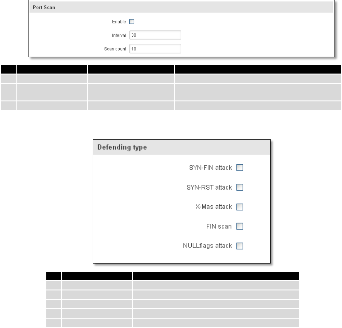
79
7.6.7 Port Scan Prevention
7.6.7.1 Port Scan
Field Name
Sample value
Explanation
1.
Enable
Enable/Disable
Enable port scan prevention
2.
Interval
30
Time interval in seconds counting how much port scan
(10 – 60 sec.)
3.
Scan count
10
How much port scan before blocked
7.6.7.2 Defending type
Field Name
Explanation
1.
SYN-FIN attack
Protect from SYN-FIN attack
2.
SYN-RST attack
Protect from SYN-RST attack
3.
X-Mas attack
Protect from X-Mas attack
4.
FIN scan
Protect from FIN scan
5.
NULLflags attack
Protect from NULLflags attack
7.7 Routing
7.7.1 Static Routes
Static routes specify over which interface and gateway a certain host or network can be reached.
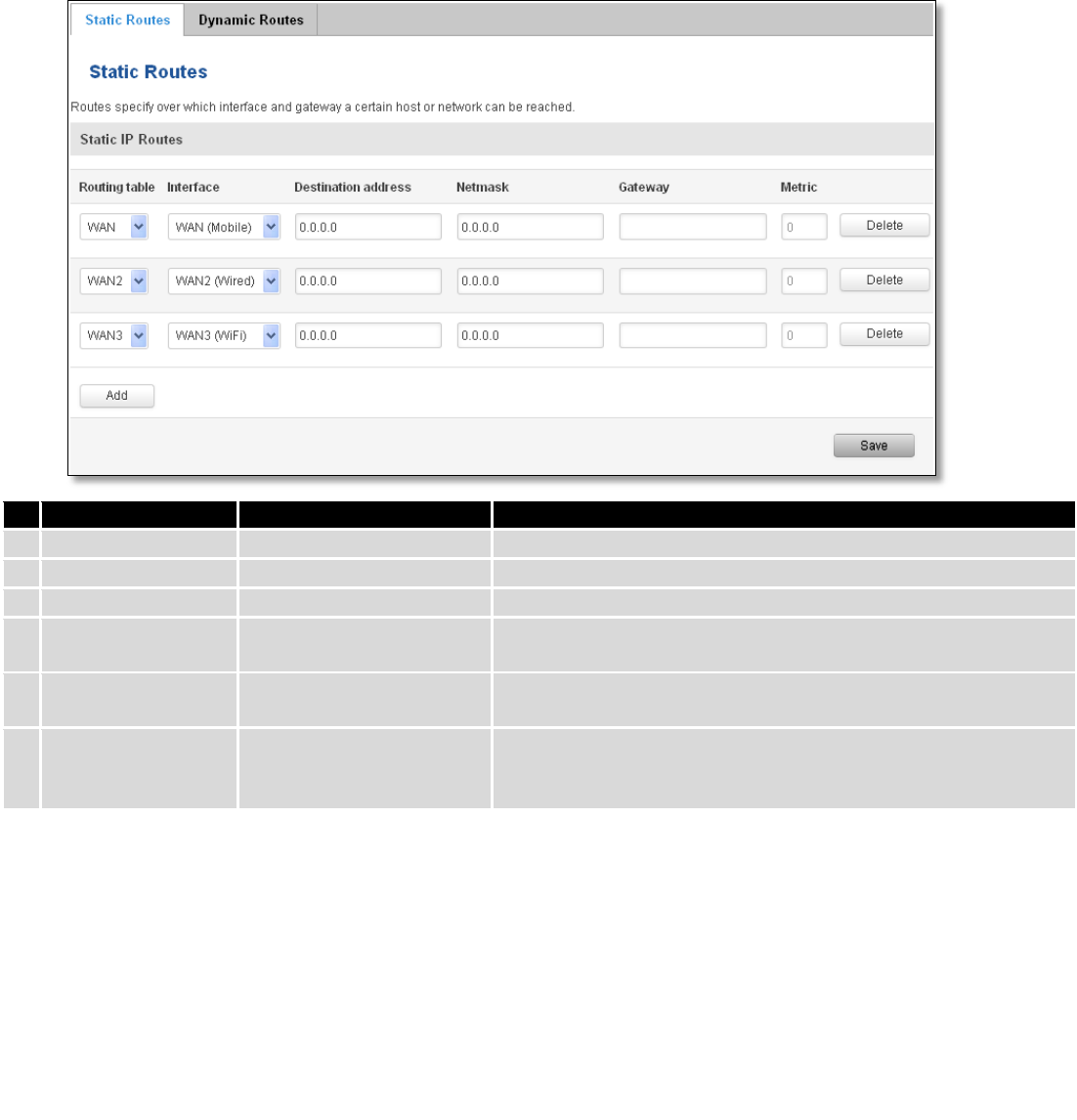
80
Field name
Value
Explanation
1.
Routing table
MAIN/WAN/WAN2/WAN3
Defines the table to use for the route
2.
Interface
MAIN/WAN/WAN2/WAN3
The zone where the target network resides
3.
Destination address
IP address
The address of the destination network
4.
Netmask
IP mask
Mask that is applied to the Target to determine to what actual
IP addresses the routing rule applies
5.
Gateway
IP address
To where the router should send all the traffic that applies to
the rule
6.
Metric
integer
Used as a sorting measure. If a packet about to be routed fits
two rules, the one with the higher metric is applied.
Additional note on Target & Netmask: You can define a rule that applies to a single IP like this: Target - some IP;
Netmask - 255.255.255.255. Furthermore you can define a rule that applies to a segment of IPs like this: Target – some
IP that STARTS the segment; Netmask – Netmask that defines how large the segment is. E.g.:
192.168.55.161
255.255.255.255
Only applies to 192.168.55.161
192.168.55.0
255.255.255.0
Applies to IPs in range 192.168.55.0-192.168.55.255
192.168.55.240
255.255.255.240
Applies 192.168.55.240 - 192.168.55.255
192.168.55.161
255.255.255.0
192.168.55.0 - 192.168.55.255
192.168.0.0
255.255.0.0
192.168.0.0 - 192.168.255.255
7.7.2 Dynamic Routes
7.7.2.1 General
Dynamic routes provide dynamic routing which enables router to select paths according to real-time logical
network layout changes.
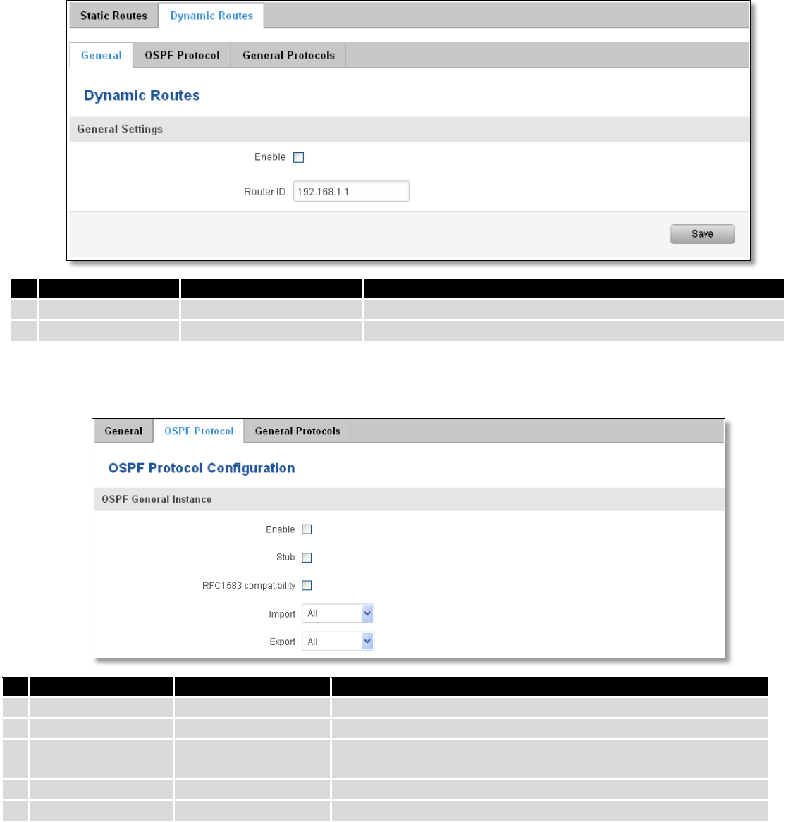
81
7.7.2.2 OSPF Protocol
7.7.2.2.1 OSPF General Instance
Field name
Value
Explanation
1.
Enable
Enable/Disable
Enables OSPF protocol
2.
Stub
Enable/Disable
Enable/Disable stub
3.
RFC1583
compatibility
Enable/Disable
Enables OSPF compatibility with RFC1583 specification
4.
Import
All/None/custom
Set if the protocol must import routes
5.
Export
All/None/custom
Set if the protocol must export routes
7.7.2.2.2 OSPF Area
The OSPF network can be divided into sub-domains called areas.
Field name
Value
Explanation
1.
Enable
Enable/Disable
Enable dynamic routes
2.
Router ID
192.168.1.1
Router’s ID
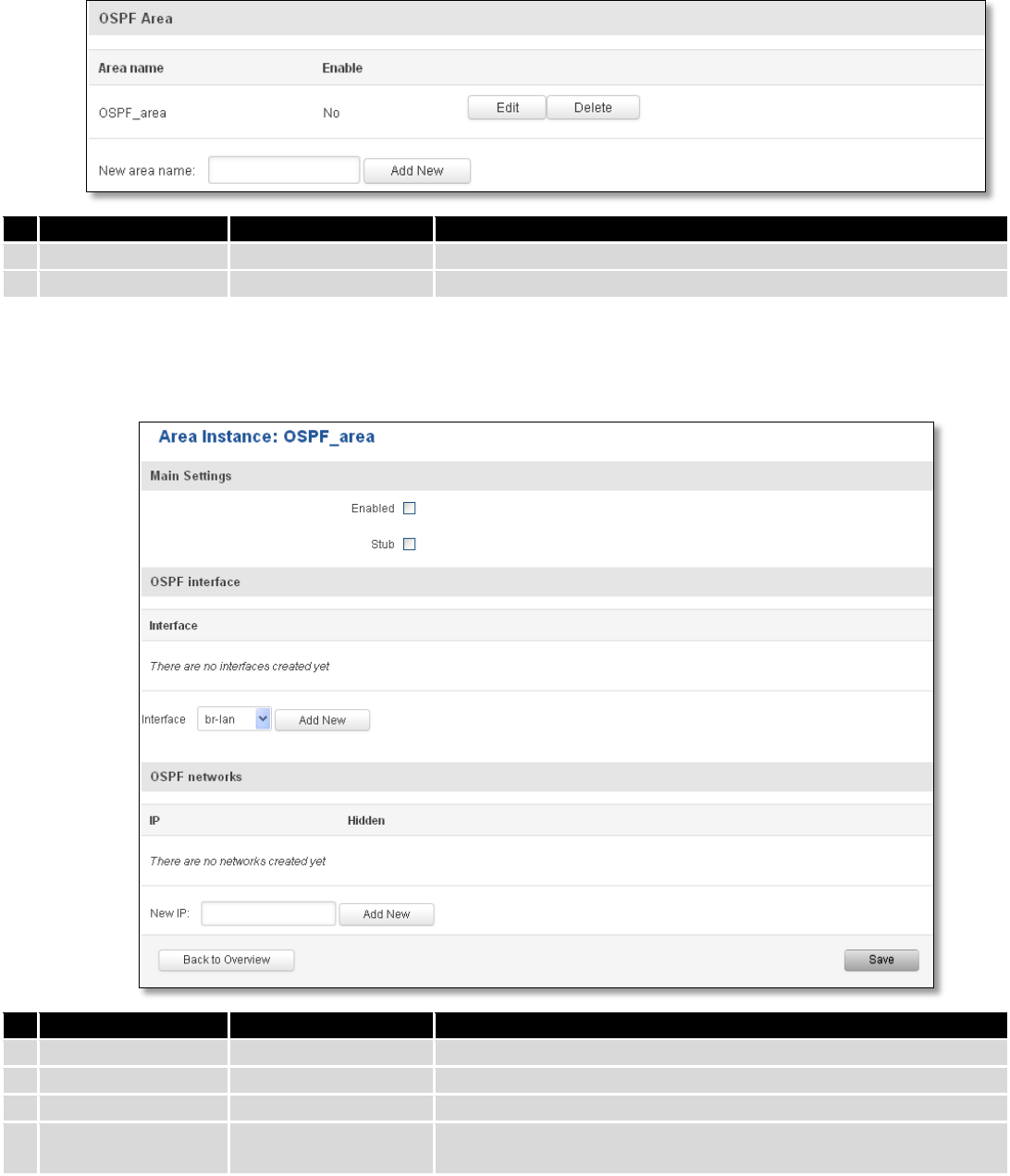
82
Field name
Value
Explanation
1.
Area name
OSPF_area
OSPF area’s name
2.
Enable
Yes/No
Enable/disable OSPF area
To see at specific configuration settings press “edit” button located in newly created OSPF area. A new page with
detailed configuration appears, as shown in the picture below.
Field name
Value
Explanation
1.
Enabled
Enable/Disable
Enable specific OSPF area
2.
Stub
Enable/Disable
Enable/disable stub
3.
Interface
br-lan
A interface that new instance will have
4.
New IP
Name of the new OSPF network configuration. Used for easer
configurations management purpose only
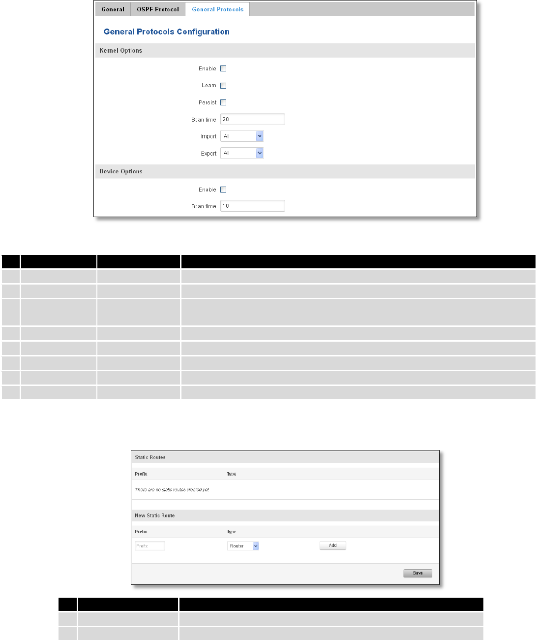
83
7.7.2.3 General Protocol
Field name
Value
Explanation
1.
Enable
Enable/Disable
Enable/Disable settings
2.
Learn
Enable/Disable
Enables routes learning
3.
Persist
Enable/Disable
If checked it allows to store routes. After a restart, routes will be still
configured
4.
Scan time
20
Time between scans
5.
Import
All
Set if the protocol must import routes
6.
Export
All
Set if the protocol must export routes
7.
Enable
Enable/Disable
If checked the protocol will not be configured
8.
Scan time
10
Time between scans
7.7.2.3.1 Static Routes
Field name
Explanation
1.
Prefix
Protocol prefix of incoming or outgoing packet
2.
Type
Protocol type of incoming or outgoing packet
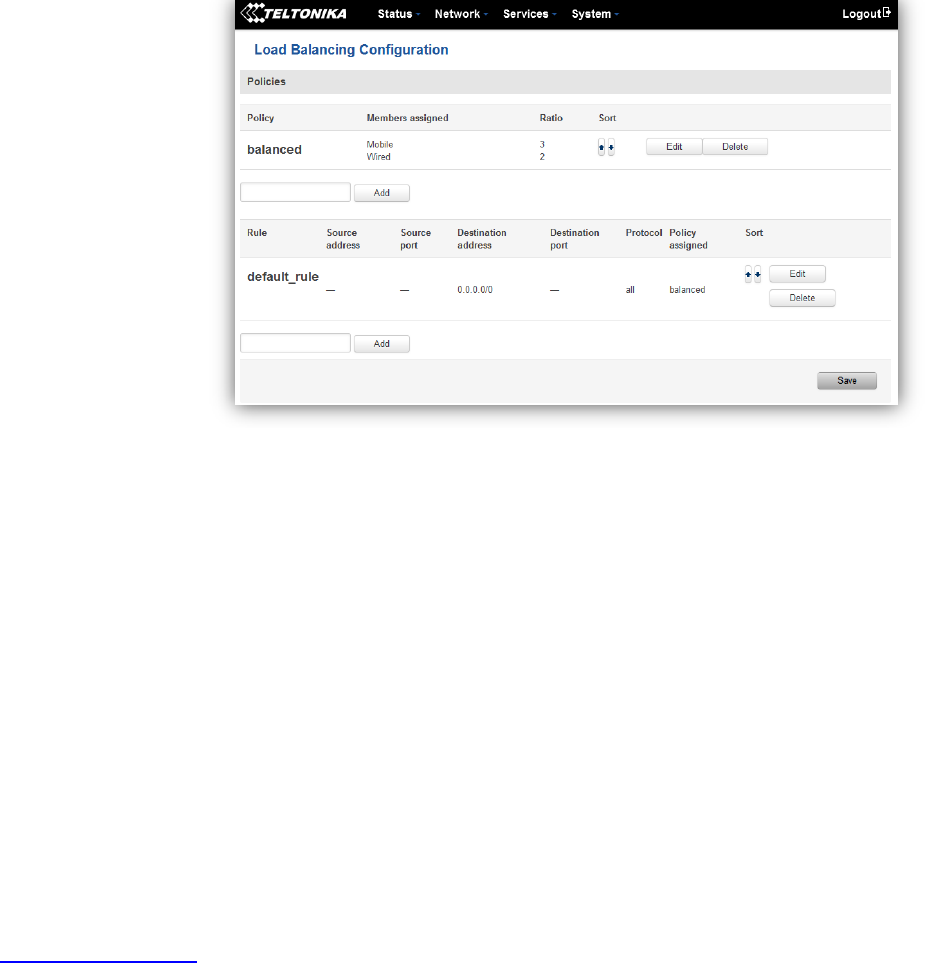
84
7.8 Load Balancing
Load balancing lets users divide traffic between different interfaces.
8 Remote monitoring and administration
RUT9XX supports multiple monitoring and administration possibilities. One can get routers information through
SMS or using RMS (Remote Management System). Furthermore, some system related parameters can be obtained using
MODBUSD or MQTT publisher services. How to use them are described in the 9.19 and 9.20 chapters respectively. The
main focus is on parameters, which change from time to time, like signal strength, operators name (it is quite common
to change of operator name in countries where inner roaming is used) or module temperature. Although it is also
possible to read more static values, like MAC address, router’s serial number and many others. The access to the
mentioned parameters is implemented in both MODBUSD and MQTT publisher applications. Apart from getting of
some parameters, MODBUSD also supports setting of some system related parameter, for example, change value of
digital output. Although it sounds frustrating, this functionality is sometimes useful and necessary.
Some applications, like MQTT publisher or RMS allows monitoring or administrating several routers from one
place. It is very useful functionality, when you have few routers and would like to change some parameter using single
application. RMS share some similarities with SSH (Secure Shell) and indeed, one of RMS feature is to allows SSH access
to remote router. There is no separate chapter about RMS in this manual, because the interface of RMS is very intuitive
and user friendly. You can access RMS by using your browser with supplied username and a password at
http://rms.teltonika.lt
By sending SMS to the router the user can execute some command, like reboot, switch wifi on or off and many
others. With each SMS the user need to specify router’s administrator password. This is done for authentication
purposes. The list of commands that may be executed through the SMS is limited. Full list of commands can be found on
Services-SMS Utilities of routers WEB page. More about router’s management using SMS can found in chapter 9.8.
Another interesting router monitoring solution is SNMP (Simple Network Management Protocol). By not going
into deep details about this protocol, it is another manner to monitor router parameters. It allows the user to check
current operator, modem model and other router parameters. Compared to other applications and services, only SNMP
have ability to inform the user about the occurrence of specific event (called trap) in the system. The main drawback of
this protocol is, that it does not allow to change anything. You can read more about SNMP in chapter 8.9.
85
Apart from services mentioned earlier, there is one service, which is used only for communication between router
and Android type device (phones, etc’). It is called json-rpc and allows to set or get various parameters of the system.
JSON-RPC can execute the same commands, like user through SSH. To sum up, this approach opens wide possibilities in
communication between router and Android. However, there is no separate topic about JSON-RPC in this manual,
because this type of communication is generally not for end-user use.
Each approach has its advantages and disadvantages. In some situations, maybe MQTT publisher works better
than MODBUSD, while in others, MODBUSD will be the better choice. The most versatile manner of system monitoring
and administration is through SSH. The SSH provides complete control of the router. The user can execute commands,
write shell scripts and do many other things. In such case, the user only needs application to connect router through
SSH. The most popular application used in Windows type operating systems is called Putty. If you try to connect to
router from Unix like operating system, you only need to execute ssh command with some arguments, like hostname
and username (in this case – root).
Sometimes the use of SSH is not necessary, so other more conservative services/applications are used. The
complete list of applications and services, which can be used for router administration and monitoring are given below.
It can be seen, that all applications, except MQTT publisher and SNMP supports setting/getting of some system related
parameter.
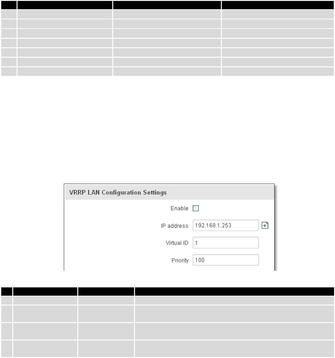
86
Application
Can obtain parameters
Can set parameters
1.
MQTT publisher
o
2.
MODBUS daemon
3.
SSH
4.
RMS
5.
SMS
6.
SNMP
o
7.
JSON-RPC
By summarizing, RUT9XX provides several solutions for router management. Each user can choose what solution
to use. If required functionality is not found in particular service, the user can combine several applications, for
example, use MQTT publisher along with SNMP. Finally, if user has special needs, he can write shell script and execute it
via SSH or use json-rpc.
9 Services
9.1 VRRP
9.1.1 VRRP LAN Configuration Settings
Field name
Sample
Explanation
1.
Enable
Enable/Disable
Enable VRRP (Virtual Router Redundancy Protocol) for LAN
2.
IP address
192.168.1.253
Virtual IP address for LAN's VRRP (Virtual Router Redundancy
Protocol) cluster
3.
Virtual ID
1
Routers with same IDs will be grouped in the same VRRP (Virtual
Router Redundancy Protocol) cluster, range [1-255]
4.
Priority
100
Router with highest priority value on the same VRRP (Virtual Router
Redundancy Protocol) cluster will act as a master, range [1-255]
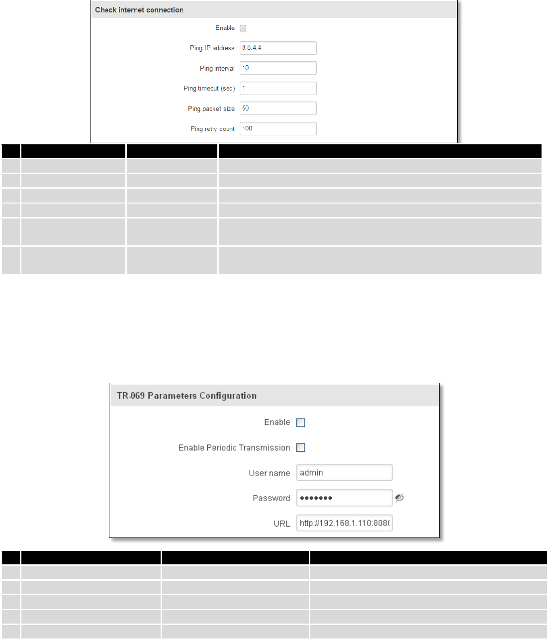
87
9.1.2 Check Internet connection
Field name
Sample
Explanation
1.
Enable
Enable/Disable
Enable WAN's connection monitoring
2.
Ping IP address
8.8.4.4
A host to send ICMP (Internet Control Message Protocol) packets to
3.
Ping interval
10
Time interval in seconds between two Pings
4.
Ping timeout (sec)
1
Response timeout value, interval [1 - 9999]
5.
Ping packet size
50
ICMP (Internet Control Message Protocol) packet's size, interval [0 -
1000]
6.
Ping retry count
100
Failed Ping attempt’s count before determining that connection is
lost, interval [1 – 9999]
9.2 TR-069
TR-069 is a standard developed for automatic configuration and management of remote devices by Auto
Configuration Servers (ACS).
9.2.1 TR-069 Parameters Configuration
Field name
Sample
Explanation
1.
Enable
Enable/Disable
Enable TR-069 client
2.
Enable Periodic Transmission
Enable / Disable
Enable periodic transmissions of data to server
3.
User name
admin
User name for authentication on TR-069 server
4.
Password
*******
Password for authentication on TR-069 server
5.
URL
http://192.168.1.110:8080
TR-069 server URL address
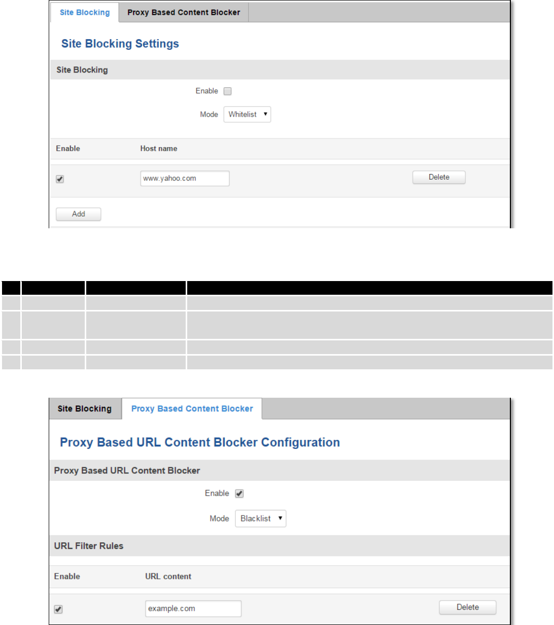
88
9.3 Web filter
9.3.1 Site blocking
Field name
Sample
Explanation
1.
Enable
Enable/Disable
Enable host name based websites blocking
2.
Mode
Whitelist/Blacklist
Whitelist - allow every site on the list and block everything else. Blacklist -
block every site on the list and allow everything else.
3.
Enable
Enable/Disable
Check to enable site blocking
4.
Host name
www.yahoo.com
Block/allow site with this hostname
9.3.2 Proxy Based Content Blocker
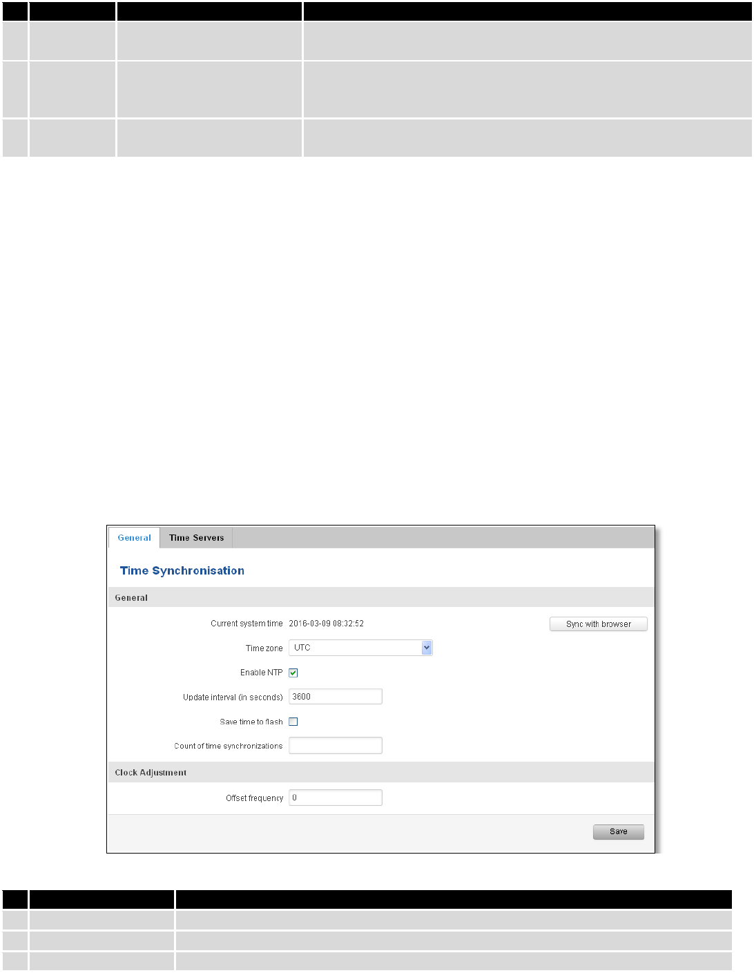
89
Field name
Sample
Explanation
1.
Enable
Enable/Disable
Enable proxy server based URL content blocking. Works with HTTP
protocol only
2.
Mode
Whitelist/Blacklist
Whitelist - allow every part of URL on the list and block everything
else. Blacklist - block every part of URL on the list and allow everything
else
3.
URL
content
example.com
Block/allow any URL containing this string. Example.com, example.*,
*.example.com
9.4 NTP
NTP configuration lets you setup and synchronize routers time.
Field name
Description
1.
Current System time
Local time of router.
2.
Time zone
Time zone of your country.
3.
Enable NTP
Enable system’s time synchronization with time server using NTP (Network Time

90
Protocol)
4.
Update interval
How often router updates systems time
5.
Save time to flash
Save last synchronized time to flash memory
6.
Count of time
synchronizations
Total amount of times that router will do the synchronization. Note: If left blank - the
count will be infinite
7.
Offset frequency
Adjust the minor drift of the clock so that it will be more accurate
Note, that under Time Servers at least one server has to be present, otherwise NTP will not serve its purposes.